Elastic stresses at a mismatched circumferential joint in ...

ELASTIC STRESSES AT A MISMATCHED CIRCUMFERENTIAL JOINT I N A PRESSURIZED CYLINDER INCLUDING THICKNESS CHANGES A N D MERIDIONAL LOAD COUPLING
by Peter T. Bizon
Lewis Research Center CZevehnd, Ohio
NATIONAL AERONAUTICS AND SPA€E ADMINISTRATION WASHINGTON, D. C. SEPTEMBER 1966
https://ntrs.nasa.gov/search.jsp?R=19660026834 2018-06-12T23:03:25+00:00Z
TECH LIBRARY KAFB. NM
ELASTIC STRESSES A T A MISMATCHED CIRCUMFERENTIAL JOINT
IN A PRESSURIZED CYLINDER INCLUDING THICKNESS
CHANGES AND MERIDIONAL LOAD COUPLING
By Peter T. Bizon
Lewis R e s e a r c h Cen te r Cleveland, Ohio
NATIONAL AERONAUTICS AND SPACE ADMINISTRATION
For sale by the Clearinghouse for Federal Scientific and Technical Information Springfield, Virginia 22151 - Price $2.00

ELASTIC STRESSES AT A MISMATCHED CIRCUMFERENTIAL JOINT
I N A PRESSURIZED CYLINDER INCLUDING THICKNESS
CHANGES AND MERIDIONAL LOAD COUPLING
by Peter T. Bizon
Lewis Research Center
SUMMARY
The results of an analytical investigation of stresses at a circumferential joint in a pressurized circular cylindrical vessel a r e presented graphically for a wide range of geometric values. This investigation of a mismatched joint with any thickness change was performed for three types of junction geometry: unfilleted butt joint, filleted butt joint, and overlap joint. These analyses include nonlinear effects for large radius-to- thickness structures that are highly stressed. This report provides design curves that predict the s t resses at such junctions; also illustrated a r e the conditions under which the meridional load coupling effect be comes important.
mismatch was varied from zero to the case where the inner surface of one cylinder coin- cided with the outer surface of the other cylinder. The lengths of overlap joints investi- gated varied from short lengths with discontinuity interactions to longer lengths with no interactions. Nonlinear edge influence coefficients, which were used to obtain the results, are presented for both semi-infinite and short-length cylinders.
drical pressure vessel, it is l e s s detrimental if the thinner section is displaced a small amount inward rather than outward from the thicker section if mismatch is to occur. It was also concluded that, if the t h i c h e s s does not change at the junction of an unfilleted butt joint, a nonlinear stress analysis is not required to determine the mismatch stresses. For equal thicknesses at a filleted butt joint, a nonlinear analysis is required to deter- mine accurat.ely the mismatch stresses.
All thickness ratios for the three joints were investigated. In the butt joints, the
It was concluded that, for a change in thickness at a circumferentiar joint in a cylin-

INTRODUCTION
Cylindrical shells that are fabricated in sections and then joined to form the com- pleted structure a re typical of many propellant tanks and pressure vessels. The sections joined circumferentially are sometimes of different thicknesses, and mismatch is often introduced during the joining process. It may be necessary to consider the effect of the meridional load on the bending stresses in order to determine accurately the s t resses for structures that are highly stressed and have a large radius-to-thickness ratio. This consideration results in a nonlinear analysis in which s t resses are not proportional to internal pressure.
Previous investigations of related subjects did not include all the parameters con- sidered herein and were usually linear in nature. The analyses presented in references 1 and 2 are linear. Reference 3 is applicable only for mismatch at junctions of equal thick- ness but in any stress field. References 4 to 6 are nonlinear analyses that include thick- ness changes but not mismatch. Reference 7 is an outline of a computer program for the analysis of reference 6. Reference 8, which includes mismatch effects, is an extension of reference 5. All these analyses a re for unfilleted butt joints only; no considerations of filleted butt joints or overlap joints were included. An analysis of a junction of equal thickness cylinders by an overlap of short length is given in reference 9. Excellent agreement between linear theory and experimental results for small scale tanks is pre- sented in references 10 and 11.
The nonlinear analyses of this investigation considered thickness changes and mis- match for unfilleted and filleted butt joints as well as for overlap joints. This report pro- vides a compilation of design curves for determining the maximum stresses near circum- ferential joints in cylindrical pressure vessels considering nonlinear effects. The con- ditions under which the nonlinear effects become important and necessitate consideration are also illustrated.
An analytical investigation was performed to determine accurately the s t resses near three types of circumferential joints: unfilleted butt, filleted butt, and overlap. Results for these three joints a r e presented graphically for any thickness ratio. In the butt joints, the mismatch studied varied from zero to the case where the inner surface of one component coincided with the outer surface of the other component. The length of over- lap joints investigated varied from short lengths with interactions to longer lengths with no interactions.
GEOMETRY AND METHOD OF ANALYSlS
General
Two semi-infinite closed-end circular cylinders (fig. l(a)), which a r e joined in one
2

I
of the three ways shown in figure l(b), are considered. As can be seen, both the filleted butt joint and the overlap joint have two discontinuities. For these circumferential joints, the analysis assumes interactions between the two discontinuities of the joint. The cy- linders are loaded by internal pressure only. It is assumed that the two cylinders are coaxial and that the radius and thickness of each are constant; however, a mismatch (eccentricity) between the middle surfaces at the joint is considered. Both cylinders are made of the same material, which is assumed to be homogeneous, isotropic, and subject to Hooke's law. The effect of stress concentration due to sharp corners at the disconti- nuity is not included.
Unfil leted Butt Joint
The geometry of an unfilleted butt joint (fig. 2(a)) can be described by the thickness ratio c and the percent mismatch m. (All symbols are defined in appendix A. ) If the subscript 1 is assigned to the smaller thickness component and the subscript 2 to the larger thickness component, the thickness ratio can be defined as
When the same subscripts are kept, the percent mismatch is defined as
m = a2 - a1 (100) (h l + h2)/2
It should be noted that the percent mismatch can be positive o r negative depending on whether a2 - a1 is positive or negative.
coefficient approach in which the cylinder is imagined cut at the discontinuity and sepa- rated into two edge -loaded cylinders. Simultaneous solution of the equations that express the equality of deflection and rotation at the discontinuity gives the shear forces and bending moments at the junction. The shear forces and bending moments for an unfilleted butt joint are given in appendix B.
The necessary edge influence coefficients were obtained from reference 12 by analogy to a semi-infinite beam on an elastic foundation with a free end. For a nonlinear analysis, the beam is loaded simultaneously with a unit end shear force or bending
The method used to determine the stresses at the joint is the usual edge influence
3

moment and an axial tensile force. Nonlinear edge influence coefficients are presented in equation (B5).
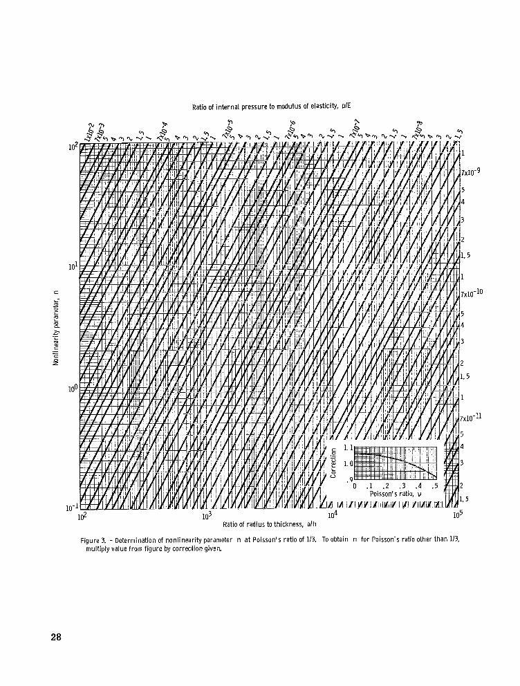
by quantities that contain a nonlinearity parameter n, which is defined as The nonlinear influence coefficients differ from the usual linear influence coefficients
(3) 2 E \hJ
The parameter n may be determined from figure 3. It is emphasized that this parameter is a function of internal pressure as well as geometry. If n is set equal to zero, the nonlinear analysis reduces to the linear analysis.
Filleted B u t t Joint
The filleted butt joint was assumed to have a 45' fillet, as shown in figure 2(b). The analysis for the filleted butt joint is similar to that of the unfilleted butt joint, except that the fillet area was treated as a ring that joins the two cylinders. The structure was imagined to be cut at each discontinuity and separated into three components. cross section was assumed to translate and rotate but not deform. cular ring were resolved to radial forces and twisting couples uniformly distributed along the centerline. familiar ring formulas that are given in references 13 and 14.
The equality of deflections and rotations at each of the two discontinuities of the filleted butt joint gave the four equations required to determine the unknown shear forces and bending moments at both discontinuities. for a filleted butt joint are given in appendix C.
The ring All loads on the cir-
The influence coefficients were then determined by modification of the
These shear forces and bending moments
Over lap Joint
The overlap joint is shown in figure 2(c). The analysis for this joint was identical to that for the filleted butt joint except that the center component was analyzed as a short cylinder instead of as a ring. ence 12 for a finite-length beam on an elastic foundation.
The equality of deflections and rotations at each of the two discontinuities of the overlap joint gave the four equations required to determine the unknown shear forces and bending moments at both discontinuities.
The edge influence coefficients were taken from refer-
These shear forces and bending moments for
4

an overlap joint are given in appendix D.
positive or negative 100-percent mismatch. The quantity required to describe an overlap joint, in addition to thickness ratio and nonlinearity parameter, is the overlap parameter X3Q, which is defined as
In the overlap joint, the percent mismatch is not applicable, since all joints have
where X 3 is the characteristic of the short center cylindrical section and Q the length of overlap. The overlap parameter is dimensionless.
Stress Determination
The total s t r e s s at any location is composed of membrane stresses and discontinuity s t resses . The stress distribution was not investigated in the ring or short cylinder components because the s t resses were relatively low due to the larger thicknesses. Equations for the stress distribution in the cylindrical components are given in appen- dix E.
The energy of distortion theory, introduced by von Mises and reinterpreted by Hencky, can be used to predict the limit of elastic behavior. This theory states that yielding will occur in a biaxial state of s t ress if a quantity called the effective stress is equal to the yield stress as determined from a uniaxial tensile test. The effective s t r e s s is defined as
The membrane s t resses in the thinner cylinder are used to determine the maximum effective membrane stress. The .maximum effective stress anywhere in the structure is then determined by using the total stresses. The ratio of the maximum effective stress anywhere in the vessel to the maximum effective membrane stress is defined herein as the s t r e s s factor K.
SUMMARY OF ASSUMPTIONS AND LIMITATIONS
The following assumptions and limitations apply to the analyses performed herein
5

and to the application of the results.
thickness are permissible. ) (1) Small finite deflection theory is assumed. (Normal deflections of the order of the
(2) Thin shell theory is applicable. (3) The cylinder has closed ends and is loaded by uniform internal pressure. (4) It is assumed that the thickness of each circular cylindrical component is constant
(5) The material is assumed to be homogeneous, isotropic, and linearly elastic. (6) The effect of stress concentrations at sharp corners is not included (i. e., plane
(7) For the filleted butt joint, the analysis assumes that the ring radius is much
(8) For the overlap joint, short cylinder equations are used in the overlap portion. (9) Stress factors a re based on the effective stress as defined in the energy of dis-
and that the axes of revolution are collinear.
sections remain plane).
larger than its thickness and that the ring has a rigid cross section.
tortion theory of yielding.
RESULTS AND DISCUSSION
In f I u e n c e Coeff ic ients
Nonlinear edge -rotation and edge -deflection influence coefficients due to edge shear force and bending moment on a circular cylinder are presented in equation (B5). These influence coefficients can be used for other shapes of shells in accordance with Geckeler's approximation (ref. 15, pp. 567-8). With these influence coefficients, nonlinear results can be obtained for discontinuity s t resses at the junctions of shells of other geometry in which the edge' tangents a re parallel to the axis of revolution.
Design C u r v e s
For all three joints, the complexity and length of the equations did not readily permit reduction to simple form. (E,v), and internal pressure (p) were selected for use in the computer programs to ob- tain the stress factors (K).
All results a r e presented for a Poisson's ratio of 1/3. A comparison with a Poisson's ratio of 0.30 resulted in a maximum s t r e s s factor variation of approximately 1 . 2 percent.
Values of the nonlinearity parameter factors a, h, p, and E were varied, but the value of the nonlinearity parameter itself was unchanged; a comparison of the corresponding
Consequently, values for geometry (a, h), material constants
6

results showed no appreciable change in K. It was concluded that K in the nonlinear range is a function of n and not its individual factors.
Stress factors for the three joints are presented for all thickness ratios. Each joint was investigated for n parameters of 0, 0.1, 1, 10, and 100. For all curves presented herein, solid lines represent Configurations in which the maximum effective stress is located at a discontinuity, and the dashed lines represent configurations in which the max- imum effective stress location is away from a discontinuity.
Unfilleted butt joint. - The results for the unfilleted butt joint are presented graphi- cally in figure 4. Stress factors K are presented for mismatch from negative to posi- tive 100 percent.
Negative mismatch (thinner cylinder displaced outward from thicker cylinder) is almost always more critical than positive mismatch of the same magnitude. This is especially true for the smaller thickness ratios, where the thicknesses are quite dis- similar. When n 2 1.0, K = 1 . 0 if the maximum effective stress location is not at the discontinuity; thus, there is no increase in K because of the discontinuity in geometry.
also investigated with a 45' filleted butt joint, as shown in figure 2(b). Stress factors were determined for mismatch from negative to positive 100 percent for all thickness ratios. The s t ress factors for the filleted butt joint a re presented in figure 5.
Filleted _ _ - butt joint. - All configurations investigated with an unfilleted butt joint were
The curves in figure 5 a re similar to the corresponding unfilleted butt joint curves in figure 4. It should be noted that, as the nonlinearity parameter increases, the stress factor is reduced for most cases. For equal thicknesses, up to a 25-percent decrease in the stress factor is possible. As for the unfilleted butt joint, when n 2 1.0, K = 1.0 if the maximum effective stress is not at the discontinuity; thus, there is no increase in K because of the discontinuity in geometry.
Overlap joint. - The overlap joint was investigated for overlap parameters hgQ from 0 to 10 for all thiclmess ratios. Stress factors for these cases a re presented in figure 6. Results for the overlap parameter of zero were taken from corresponding cases of a positive or negative 100-percent unfilleted butt joint.
When the overlap parameter is 10 or greater, no interactions occur between the discontinuities of the joint; the junction can be treated, therefore, as two unfilleted butt joints that are far enough apart that they do not interact. The stress factors for overlap joints with an overlap parameter of 10 were compared with the corresponding results for an unfilleted butt joint; the results are identical.
to.corresponding joints with negative overlap; that is, it is preferable from a stress viewpoint to mate the outside surface of the thinner component to the inside surface of the thicker component. For negative overlap, the stress factor decreases as the overlap parameter is increased. For positive overlap, however, a long overlap length is desired
As can be seen in figure 6, overlap joints with positive overlap are usually preferred
7

only for thickness ratios greater than approximately 0.25. For smaller thickness ratios, a shorter overlap length is preferred so that the lowest stress factors possible can be obtained. For negative overlap and a given overlap parameter, the stress factor de- creases with increasing nonlinearity. For positive overlap and a given overlap length, the stress factor increases for some thickness ratios but decreases for equal thicknesses as well as for smaller thickness ratios with increasing nonlinearity. Where n 2 1.0, K = 1.0 if the maximum effective stress is not at the discontinuity.
Comparisons of Resu Its
Pressurized cylinder with fixed ends. - - An analysis was performed for a cylindrical shell that had fixed ends (with longitudinal expansion possible) and that was loaded by a uniform internal pressure. A nonlinear analysis for the fixed-end cylinder resulted in an equation for a s t ress factor that was independent of the nonlinearity parameter n. It was found that this equation, which is a function of Poisson's ratio only, is the same as would be obtained from the usual linear analysis. These results are given in figure 7.
From the results shown in figure 7 for a fixed-end cylinder with v = 1/3, a value of K = 2.068 is obtained. It is observed in figure 8 that the fixed-end cylinder is approached for very small thickness ratios, and that, for these thickness ratios, K is linear with per cent mismatch.
Filleted compared with unfilleted butt joint. - A comparison of the stress factors for unfilleted butt joints (fig. 4) with corresponding filleted butt joints (fig. 5) was made to determine the effect on K of adding a 45' fillet. It is emphasized that stress concen- tration at sharp corners has been neglected in this comparison. For equal thicknesses at the discontinuity, linear results show a 2-percent decrease in the s t ress factor when the 45' fillet is added; the decrease did not exceed 4 percent for any thickness ratio.
For the nonlinear results, a considerable decrease in the stress factor is obtained by adding the 45' fillet. most thickness ratios (including equal thicknesses).
Linear compared ~ _ _ with nonlinear results. _ _ - - One result of a comparison of linear and nonlinear results for unfilleted butt joints with positive mismatch and thickness ratios greater than about 0.17 but less than 0.8 is that a linear analysis may be unconservative and give a s t ress factor as much as 30 percent too low. For these joints with positive mismatch, the s t ress factor K increases as the nonlinearity parameter n increases. For most other unfilleted butt joints, the s t ress factor decreases with increasing nonlinearity.
Another result of a comparison between linear and corresponding nonlinear unfilleted butt joints was that, for equal thicknesses at the joint, c = 1.0, the stress factors were independent of the amount of nonlinearity. When this comparison was performed for a
For n = 100, this decrease can be as much as 25 percent for
8

filleted butt joint with equal thicknesses, a considerable decrease (up to 25 percent) in stress factor with increasing nonlinearity was noted.
For the three joints investigated, if the nonlinearity parameter n was about 0.8 or less, the difference between corresponding linear and nonlinear cases was no more than 5 percent. Thus, for n less than about 0.8, linear junction analyses can be used.
SAMPLE PROBLEM
A sample problem illustrates the use of the design curves. The configuration selected for the sample problem is illustrated in figure 9. Two stainless-steel cylinders of 120-inch nominal diameter have a 1/2-inch overlap and are pressurized to 35 pounds per square inch.
The necessary constants a r e the following:
Middle surface radius of thinner cylinder, al, in. Middle surface radius of thicker cylinder, a2, in. Thickness of shell wall of thinner cylinder, hl , in. Thickness of shell wall of thicker cylinder, h2, in. Length of overlap, Q, in. . . . . . . . . . . .
Modulus of elasticity, E, psi . . . . . . . . . Internal pressure, p, psi . . . . . . . . . . .
Poisson's ratio, I/ . . . . . . . . . . . . . .
. . . . . . . . . . . . . . . . 6 0
. . . . . . . . . . . . . 60.0135 . . . . . . . . . . . . . 0.0'13 . . . . . . . . . . . . . 0.014
. . . . . . . . . . . . . . . 0 .5
. . . . . . . . . . . . . . . 0.3
. . . . . . . . . . . . . . . . 35
. . . . . . . . . . . . . . . . 3 0 ~ 1 0 ~
Since the thicker cylinder is displaced outward from the thinner cylinder, this is positive overlap. To completely specify a positive overlap joint, it is necessary to determine the thickness ratio, overlap parameter, and nonlinearity parameter:
Thickness ratio:
Overlap parameter:
3 Q = { C Q = { T O . 5 = 0.505 a3h3 (60.007) (0.027)
9

Nonlinearity parameter :
35 = 1. 17X10-6 al - 60 - _ - = 4 6 1 5 = hl 0.013 E 30X106
From figure 3, nl = (1.012)(20. 3) = 20.5 It is now possible to firid the stress factor by cross plotting. It is necessary to
select s t r e s s factors for three nonlinearity parameters to determine accurately the stress factor for the specified example. For a thickness ratio of 0.929 and an overlap parameter of 0.505, stress TABLE I. -
FOR SAMPLE PROBLEM
Nonlinearity parameter,
n
1 . 0
10
100
Stress bctor,
K
1. 51
1.205
1.175
Figure
factors are determined for the nonlinearity parameters in table I. Although these stress factors are for v = 1/3 in- stead of I/ = 0.30, it was noted previously (p. 6) that the result will be within 4 . 2 percent. A plot of the stress factors in figure 10 results in a stress factor of 1.19 for this example (n = 20. 5). This same factor would be obtained for a corresponding unfilleted butt joint with about 30 percent mismatch and a corresponding filleted butt joint with about 34 percent mismatch.
CONCLUSIONS
Stress factors are presented in a set of design curves for circumferential joints in internally pressurized circular cylinders. Also presented a re nonlinear edge influence coefficients for semi-infinite and short-length cylinders. linear and nonlinear results as well as between unfilleted butt, filleted butt, and overlap joints. Effects of s t r e s s concentrations at sharp corners are not considered. The following observations can be made:
1. For a change in thickness at a circumferential joint in a cylindrical pressure vessel, it is less detrimental if the thinner section is displaced inward rather than out- ward from the thicker section if mismatch is to occur.
2. If the thickness does not change at the junction of an unfilleted butt joint, a non- linear stress analysis is not required to determine the mismatch stresses.
3. For equal thicknesses at a filleted butt joint, the s t r e s s factor decreases as the nonlinearity increases. A decrease in the stress factor of up to 25 percent is possible for some filleted butt joints.
Comparisons are made between
10

4. For overlap joints, a long overlap length is desirable only for nearly equal thick- nesses. For widely differing thicknesses, a shorter length of overlap is preferable.
5. For all three joints investigated, if the nonlinearity parameter n.
2
2 E h n = v3(1 - ’ ) p(z)2 is about 0.8 or less, a difference between the linear and nonlinear
results of no more than 5 percent is obtained.
Lewis Research Center, - National Aeronautics and Space Administration,
Cleveland, Ohio, May 19, 1966, 124-11-06-01-22.
11

APPENDIX A
SYMBOLS
A
a
b
C
D
d
E
h
Ir r
K
P
M
m
N
n
P
12
2 area of ring cross section, in.
middle surface radius of cylinder, in.
width of ring bR + bL, in.
thickness ratio, hl/h2
flexural rigidity of cylinder
, lb-in. Eh3
12(1 - u2)
difference in middle surface radii a2 - al, in.
modulus of elasticity, psi
thickness of shell wall, in.
centroidal moment of inertia of ring cross section about radial
4 axis, iil.
s t ress factor (eq. (E9))
length of overlap, in.
bending moment, (in. -lb)/in.
"2 - al per cent mismatch, (hl + h2)/2
average axial s t ress resultant in (a1 +- a 4
wall of shell . lb/in. I .
2 2
nonlinearity parameter,
internal pressure, psi
Q X
Y
6
e
h
V
0
w
shear stress resultant, lb/in.
distance along meridian from dis- continuity, in.
radial deflection of cylinder, in.
edge-deflection influence coef - ficient
meridional rotation, rad
characteristic y x , in.-l 2 2 a h
Poisson's ratio
normal stress, psi
edge -rotation influence coefficient
Subscripts :
d discontinuity
e effective
i inner surface
L
m membrane.
max maximum
0 outer surface
R
t total
X meridional direction
e circumferential direction
1 thinner cylinder
2 thicker cylinder
3 overlap cylinder or ring
left of overlap cylinder o r ring
right of overlap cylinder or ring

APPENDIX B
SHEAR AND MOMENT AT. UNFILLETED BUTT JOINT
The geometry and sign convention for an unfilleted butt joint is shown in figure 2(a). If the discontinuity forces are directed as shown in the figure, equilibrium of forces at the junction gives
J M2 = M1 + Nd
where
Nd = (E "1 + "2 )(a2 - al) = (ai - a;)
With the usual edge influence coefficient analysis, a simultaneous solution of the equa- tions that express the equality of deflections and rotations at the joint and equation (Bl) gives
The well-known influence coefficients due to internal pressure for circular cylindri- cal shells are (ref. 15)
2
w l , p = 0 w = o 2, P
13
I I l l 1 l 1 l 1 1 l I l l I l l

The remaining eight edge influence coefficients, which can be obtained from a reduction of equations given in reference 12, a r e
I -\
1
w2, M
These are nonlinear edge 'influence coefficients, and when the nonlinearity parameter n is set equal to zero, the usual linear edge influence coefficients result.
Substitution of the edge influence coefficients of equations (B4) and (B5) in equa- tion (B3) gives the discontinuity shear and moment for the thinner shell. The substitution
of equation (B3) into equation (Bl) gives the discontinuity shear and moment for the thicker shell. Once the discontinuity shear and moment have been determined, it is possible to find the deflection and stresses at any location (appendix E).
14

APPENDIX C
SHEAR AND MOMENT AT FILLETED BUTT JOINT
In the filleted butt joint, the structure is imagined cut at each discontinuity and separated into three components, with the center component treated as a ring of rigid cross section. The notation and sign convention used in this analysis is given in fig- ure 2(b).
gives four equations for determining the shear and moment on each cylindrical section: The combination of compatibility and equilibrium equations for each discontinuity
g3=Q1(W3R,QR - o l , Q ~ i - Q 2 ( 0 3 R , Q L ) i - M 1 ( W 3 R , M R - W 1 , M 1 ) + M 2( o 3R,ML)
where
g3 = p(wl, p - W3R, p)
g4 = p(wz, p - O3L, p )
I
[(a1 - "3lw3L, MR (a2 - "3lw3L, ML IJ For solution of these equations, 32 influence coefficients a r e required. The 20 influence coefficients for the ring section a r e determined by modification of the equations for a standard ring analysis, given in references 13 and 14. These influence coefficients are
15

2 - a3bL
63L7 ML - E [I,, + n b h 2 / d G ]
63L7MR= - E[$, + n b h 2 / d a ]
6 I L . p . E A ( 1 - i ) a P
- - a P L W ~
3L7 QL E [I,, + n b h 2 / m ]
= - " 8 R 3L7 QR W
E[I,, i n b h 2 / d z - ]
2
.[I,, + n b h 2 / m ]
a3 W 3L7 ML= -
2
E [I,, + n b h 2 / d a ] - a3
3L, MR - W
W 3L7p= O
- " 3 R
63R7 MR - E[I,, i n b h 2 / { s ]
2 - - - "QbR -
63R7 ML E [I,, + n b h 2 / G ]
W - - +R .~
3R7 QR E [I,, + n b h 2 / d x ]
= - 4 b L 3R7 QL
E [I,, + n b h 2 / ) / 3 ( a 1
W
2
E [I,, i nbh2//3(1-2,]
- a3 3R7 MR - - 0
2 a, J - 3R7 ML - W
E [I,, + nbh2/d=.]
W3R7 p =
16

The 12 influence coefficients for the cylindrical components a re given in equations (B4) and (B5).
to substitute the 32 influence coefficients in equations (Cl) and (C2). Then, from a solu- tion of these four equations, the unknown discontinuity shears and moments are deter- mined. Once these are known, the deflection and stresses at any location of the cylindri- cal portions can be found (appendix E).
In order to obtain the stress distribution for a filleted butt joint, it is first necessary
17

APPENDIX D
cos(A3Q G3) _--_--_-------_
_ - - _ _ _ _ _ _ _ _ _ _ _ _
SHEAR AND MOMENT AT OVERLAP JOINT
-----
1
A3Q
The analysis at the overlap joint is very similar to the filleted butt joint analysis. In the overlap joint, the structure is imagined cut at each discontinuity and separated into three components, with the center component treated as a short-length cylinder. The notation and sign convention used in this analysis is given in figure 2(c). The combina- tion of compatibility and equilibrium equations for each discontinuity gives four equations for determining the shear and moment on each cylindrical section (see eqs. (Cl) and
(C2)). TABLE 11. - CHANGES FOR OVERLAP
EQUATIONS WHEN NONLINEARITY
PARAMETER no 5 1
Terms in eqs. (Dl) and (E5) for n3 > 1
I
n3 - 1
sinh(A3Q G) cosh(A3Q m)
"3
The 16 edge influence coefficients due to edge shear force and bending moment for the overlap cylinder were determined from equations for a finite-length beam on an elastic foundation with free ends loaded by both an axial force and a unit-concentrated shear force or bending moment. The edge influence coefficients were taken from a modification of equations (104) and (105) of reference 12. These coefficients a re depen- dent on whether the nonlinearity parameter n is less than, equal to, o r greater than 1. The influence coefficients for n3 > 1 are
3
18

s i n h ( A 3 i )/l+nl)cosh(A3P 6) +c ( z ) s i n h ( A 3 i G l ) c o s h ( 1 3 P 6 1 )
sinh2(h3P F3)- 3 ( 3 y n3 - 1 1 +2n3 s i n h 2 ( A 3 i G) 1 6
*3L, ML = *3R, MR = - __ A3D3 1 + 2n3
19

Because of complexity and length, the equations are presented only for n3 > 1, where nonlinearity effects are more important. The changes necessary for use of these equa- tions when n3 d l , however, will be presented.
two sets of equations are compared, it is found that three changes in equation (Dl) will result in the equations for n3 < 1. These changes are given in table II.
When n3 < 1, certain te rms in equation (Dl) become imaginary numbers. When the
When n3 = 1, an indeterminate quantity in equation (Dl) becomes
after L'H5pital's rule is applied. Therefore, equation (Dl) will be applicable for n3 = 1 if the changes given in table 11 are performed.
a r e due to internal pcessure, - a r e determined in the same manner as for components 1 and 2. These can be stated as
The four influence coefficients for component 3 (the short overlap cylinder) , which
3R,p = w3L,p = w
The remaining 12 nonlinear influence coefficients are for the cylindrical components 1 and 2 and are given in equations (B4) and (B5).
In order to determine the discontinuity shear forces and bending moments for an overlap joint, it is first necessary to substitute the 32 influence coefficients in equa- tions (Cl) and (C2). shear forces and bending moments a re determined. Once these are known, the deflection and stresses at any location in the cylindrical portions can be found (appendix E).
From a solution of these four equations, the unknown discontinuity
20

APPENDIX E
STRESS DETERMINATION
The total stress at any location in the cylindrical components is composed of mem- brane s t resses and discontinuity stresses. The well-known membrane stresses are as follows: Meridional membrane stress:
Circumferential membrane stress :
(T = c r =pa 0 , m , i 0 ,m,o h
The discontinuity stresses are determined from the equations for a semi-infinite right circular cylindrical shell subjected to the action of shear forces and bending mo- ments uniformly distributed along the edge x = 0. These discontinuity stresses are the following: Meridional discontinuity stress:
6
h2 (T x, d, i - - -0 x, d, 0 =-Md,x
Circumferential discontinuity stress:
6v + - M h2
- E 0 , d, i - a yd, x cr
J - E 6v 0 , d, o - a Y d , x - Md, x 0
h
The discontinuity deflection and bending moment distribution as a function of x can be determined by combining equations (100) and (101) of reference 12. These equations are dependent on whether the nonlinearity parameter n is less than, equal to, or greater than 1. For brevity, the equations are presented only for n > 1 where nonlinear effects
21
I1 I I l l II Ill1 llllll11l1llll

are more important. For n 5 1, the equations should be changed in the manner given in table II. The equations for n > 1 are
Md, x = e x p ( - A x d G ) { M k o s h ( A x d x ) + dF(e ) s inh (Axdz i 1 1 + 2 n
The total s t r e s s is the sum of the membrane and discontinuity s t resses . The addi-
tion of corresponding stresses gives
ax i = u + u 9 9 x , m , i x , d , i
U = u + u x , t , o x , m , o x ,d ,o
uO, t , i=uO,m, i + u Q , d , i
U = u + u e , t , o e , m , o e ,d ,o
The effective total stresses, defined by using the energy of distortion theory for a biaxial state of stress condition, are
22

The maximum effective membrane stress, which is always in the thinner shell, is
The stress factor K is the ratio of the largest value given by equation (E7) to equation (E8) and is
(J e, t, max K = (J e ,m, 1
23

f l r i
REFERENCES
1. Johns, Robert H. ; and Orange, Thomas W. : Theoretical Elastic Stress Distributions Arising from Discontinuities and Edge Loads in Several Shell-Type Structures. NASA TR R-103, 1961.
2. Menkes, E. G. : A Note on Discontinuity Stresses in Cylindrical Shells. J. Aero. SCi. , vol. 29, no. 5, May 1962, pp. 619-620.
3. Johns, Robert H. : Theoretical Elastic Mismatch Stresses. NASA TN D-3254, 1966.
4. Wilson, P. E. ; and Spier, E. E. : Numerical Analysis of Small Finite Axisymmetric Deformation of Thin Shells of Revolution. Rep. No. ERR-AN-153, General Dynamics/Astronautics, June 1, 1962.
5. Wittrick, W. H. : Interaction Between Membrane and Edge Stresses for Thin Cylin- ders Under Axially Symmetrical Loading. J. of the Roy. Aeron. SOC., vol. 67, no. 627, Mar. 1963, pp. 172-174.
6. Smith, George W. : Derivations for the Analysis of Multiple Discontinuities in Shells of Revolution Including the Coupled Effects of Meridional Load. Rep. No. AS-D-872, General Dynamics/Astronautics, July 5, 196 3.
7. Smith, George W. : Analysis of Multiple Discontinuities in Shells of Revolution In- cluding Coupled Effects of Meridional Load. Rep. No. GD/A 63-0044, General Dynamics/Astronautics, July 31, 1963.
8. Wittrick, W. H.": Non-Linear Discontinuity Stresses in Shells of Revolution under Internal Pressure. Int. J. Eng. Sci. , vol. 2, May 1964, pp. 179-188.
9. Sechler, E. E. : Stress Rise due to Offset Welds in Tension. Rep. No. EM 9-18 (TR-59-0000-00774), Space Technology Labs. , Inc. , Aug. 28, 1959.
10. Morgan, William C. ; and Bizon, Peter T. : Experimental Investigation of Stress Distributions near Abrupt Change in Wall Thickness in Thin-Walled Pressurized Cylinders. NASA TN D-1200, 1962.
11. Morgan, William C. ; and Bizon, Peter T. : Comparison of Experimental and Theoretical Stresses at a Mismatch in a Circumferential Joint in a Cylindrical Pressure Vessel. NASA TN D-3608, 1966.
12. Hetgnyi, M. : Beams on Elastic Foundations. Univ. Mich. Press, 1946.
13. Timoshenko, S. : Elementary Theory and Problems. Pt. I of Strength of Materials, Third ed. , D. Van Nostrand Co. , Inc., 1955, pp. 31-32.
24

14. Timoshenko, S. : Advanced Theory and Problems. Pt. I1 of Strength of Materials, Third ed. , D. Van Nostrand Co. , Tnc. , 1957, pp. 138-140.
15. Timoshenko, S. ; and Woinowsky-Krieger, S. : Theory of Plates and Shells. Second ed. , McGraw-Hill Book Co. , Inc. , 1959.
25

(a) Junction of two semi-infinite c i rcular cylinders.
Unf i l leted butt joint
Filleted butt joint
Overlap joint
(b) I l lustration of joints.
Figure 1. - Configurations investigated.
26

(a) Unfilleted butt joint.
'Y3Lt ttY3R
+Y1
1 f +e1 Y ,-hl
_ _ Axis of revolution
(b) 45" Filleted butt joint.
Axis of revolution
(c) Overlap joint
Figure 2. - Geometry and sign convention.
27
c
102
Ratio of in ternal pressure to modulus of elasticity, plE
103 io4 Ratio of radius to thickness, a lh
10'
Figure 3. - Determination of nonlinearity parameter n a t Poisson's rat io of 1/3. To obtain n for Poisson's ratio other than 1/3, multiply value from f igure by correction given.
28

P u (a) Nonlinearity parameter for th inner cylinder, 0; mismatch, negative. m c
0 . 1 .2 . 3 Thickness ratio, hl/h2
(b) Nonlinearity parameter for th inner cylinder, 0; mismatch, positive.
Figure 4. - Stress factors for unfilleted butt j o i n t Poisson's ratio, 1/3.
29

(c) Nonlinearity parameter for th inner cylinder, 0.1; mismatch, negative.
Thickness ratio, hl/h2
(d) Nonlinearity parameter for th inner cylinder, 0.1; mismatch, positive.
Figure 4. - Continued.
30

= (e) Nonlinearity parameter for th inner cylinder, 1; mismatch, negative.
Thickness ratio, h l / h 2
( f ) Nonlinearity parameter for th inner cylinder, 1; mismatch, positive.
Figure 4. - Continued.
31

i 0 c " m (g) Nonlinearity parameter for th inner cylinder, 10; mismatch, negative.
(h) Nonlinearity parameter for th inner cylinder, 10; mismatch, positive.
Figure 4. - Continued.
32
I I

Y
i c 0 (i) Nonlinearity parameter for th inner cylinder, 100; mismatch, negative.
v) Ln
E c VI 2.
2.
1.
1.
1.
1.
1.
33
. .-

Y L'
Y s (a) Nonlinearity parameter for th inner cylinder, 0; mismatch, negative.
Thickness ratio, h l / h 2
(b) Nonlinearity parameter for th inner cylinder, 0; mismatch, positive.
Figure 5. - Stress factors for 45" filleted butt joint. Poisson's ratio, 113.
34

Y
L c 0 (c) Nonlinearity parameter for th inner cylinder, 0.1; mismatch, negative.
VI VI 0) L
5;
Thickness ratio, h l / h 2
(d) Nonlinearity parameter for th inner cylinder, 0.1; mismatch, positive.
Figure 5. - Continued
35

2.
2.
1.
1.
1.
1.
1. L-
4.4 0 (e) Nonlinearity parameter for th inner cylinder, 1; mismatch, negative. V m c
v) VI a, L - m
36

i c 0 Y
(g) Nonlinearity parameter for th inner cylinder, IO; mismatch, negative.
Thickness ratio, hl/hp
(h) Nonlinearity parameter for th inner cylinder, 10; mismatch, positive.
Figure 5. - Continued.
37

2.2
2.0
1.8
1.6
1.4
1. 2
1. 0 c
”.- u m
s 2 (i) Nonlinearity parameter for th inner cylinder, 100; mismatch, negative,
Y)
L c v)
2.
1.
1.
1.
1.
1.
Thickness ratio, h l / h 2
(j) Nonlinearity parameter for th inner cylinder, 100; mismatch, positive.
Figure 5. - Concluded.
38

Y (a) Nonlinearity parameter for th inner cylinder, 0; overlap, negative.
Thickness ratio, hl/h2
(b) Nonlinearity parameter for th inner cylinder, 0; overlap, positive.
Figure 6. - Stress factors for overlap joint. Poisson's ratio, 1/3.
39

(c) Nonlinearity parameter for th inner cylinder, 0.1; overlap, negative.
Thickness ratio, hl/h2
(d) Nonlinearity parameter for th inner cylinder, 0.1. overlap, positive.
Figure 6. - Continued.
40

z (e) Nonlinearity parameter for th inner cylinder, 1; overlap, negative.
0 .1 .2 . 3 . 4 .5 .6 . 7 Thickness ratio, hl/h2
(f) Nonlinearity parameter for th inner cylinder, 1; overlap, positive.
Figure 6. - Continued.
41

si (g) Nonlinearity parameter for thinner cylinder, 10; overlap, negative.
Thickness ratio, h l l h 2
(h) Nonlinearity parameter for thinner cylinder, IO; overlap, positive.
Figure 6. - Continued.
42

2.2
2.0
Y (i) Nonlinearity parameter for th inner cylinder, 100; overlap, negative.
Thickness ratio, h l l h 2
(j) Nonlinearity parameter for th inner cylinder, 100; overlap, positive.
Figure 6. - Concluded.
43

2 5
2 4 Y
L- O c
2 2 3
5(
VI If8
2.2
2.1
L O U - 0 .05
26--
\ \
~~~
__-
_ _ ~
'\ \
\ \ \
\
\ \
-\
.IO .15 20
\
i
.30 .35 40 .45 .50 Poisson's ratio, v
Figure 7. - Stress factor as function of Poisson's ratio for pressurized c i rcu lar cylinder with fixed ends (longitudi- nal expansion permitted).
-100 -80 -60 -40 -20 0 20 40 60 Percent mismatch, m
Figure 8. - Stress factors for unfilleted butt joints with small thickness ratios.
44

-.-I 0.5" 4
Figure 9. - Geometryand loading for sample problem. Modulus of elasticity, 30~10~ pounds per square inch; Poisson's ratio, 0.3.
'\
10 Nonlinearity parameter for thinner cylinder, n 1
Figure 10. - Graphical determination of stress factor for sample problem.
E- 3090 NASA-Langley, 1966
h2 0.014"
45

“The aeronautical and space activities of the United States shall be conducted so ar to contribute . . : to the expansion of human knowl- edge of phenomena in the atmosphere and space. The Adminirtration shall provide for the widest practicable and appropriate dissemination of information concerning its activities and the results thereof .”
-NATIONAL AERONAUTICS AND SPACE ACT OF 1958
NASA SCIENTIFIC AND TECHNICAL PUBLICATIONS
TECHNICAL REPORTS: important, complete, and a lasting contribution to existing knowledge.
TECHNICAL NOTES: of importance as a contribution to existing knowledge.
TECHNICAL MEMORANDUMS: Information receiving limited distri- bution because of preliminary data, security classification, or other reasons.
CONTRACTOR REPORTS: Technical information generated in con- nection with a NASA contract or grant and released under NASA auspices.
TECHNICAL TRANSLATIONS: Information published in a foreign language considered to merit NASA distribuiion in English.
TECHNICAL REPRINTS: Information derived from NASA activities and initially published in the form of journal articles.
SPECIAL PUBLICATIONS: Information derived from or of value to NASA activities but not necessarily reporting the results .of individual NASA-programmed scientific efforts. Publications include conference proceedings, monographs, data compilations, handbooks, sourcebooks, and special bibliographies.
Scientific and technical information considered
Information less broad in scope but nevertheless
Details on the availability of these publications may be obtained from:
SCIENTIFIC AND TECHNICAL INFORMATION DIVISION
NATIONAL AERONAUTICS AND SPACE ADMINISTRATION
Washington, D.C. PO546