EKPU: EFFECT OF TENSILE LOAD ON THE MECHANICAL …
5
EKPU: EFFECT OF TENSILE LOAD ON THE MECHANICAL PROPERTIES OF AlSiC COMPOSITE MATERIALS 301 *Corresponding author: [email protected] doi: http://dx.doi.org/10.4314/njtd.v17i4.8 ABSTRACT: Aluminium Silicon Carbide (AlSiC) composite materials are used in the electronics industries and other manufacturing companies hence, manufacturing of AlSiC composite materials with the right properties for different applications are vital to most industries. The challenge of testing the same specimens for different properties remains, because most of the tests carried out are destructive. Hence, the use of ANSYS finite element simulation software for the design and analysis of a flat bar specimen. Loads between 3 kN to 21 kN were applied on the specimen since it is within the operating limit of a Universal Tensile Testing Machine (UTTM), while both ends are fixed. The AlSiC composite materials used in this study have a composition of 63 vol% Al (356.2) and 37 vol% SiC and, the results showed that stress was directly proportional to strain. While the calculated Young’s modulus from the stress versus strain plot was approximately 167 GPa for the different tensile loads applied. In addition, the total deformation of the AlSiC composite material increased as the load was increased. Also, the highest deformation of the material was observed around the centre of the test specimen. This is synonymous with the failure observed in practical testing of specimens. KEYWORDS: AlSiC, tensile load, aluminium MMC, stress analysis, deformation, ANSYS [Received May 31, 2020, Revised Oct. 28, 2020, Accepted Nov. 9, 2020] Print ISSN: 0189-9546 | Online ISSN: 2437-2110 I. INTRODUCTION The quest for alternative materials as against the traditional materials of aluminium and copper in the electronic and automobile industries are on the increase in recent years (Ekpu et al., 2011). Aluminium metal matrix composite (Al-MMC) materials are readily been researched because of the potential properties the materials exhibits, such as light weight, high strength, stiffness, greater resistance to corrosion, oxidation and wear (Meena et al., 2013). Agnihotri and Dagar (2017), also stated that aluminium and its alloys possess excellent properties such as low density, good plasticity and ductility. The researchers noted that the mechanical properties of the cast metal matrix composites can be greatly impacted by the production process variables such as stirring speed, holding temperature, the position of the impeller, and size of the impeller. Their research inferred that the mechanical properties of the AlSiC composite material, such as the hardness and tensile strength were improved by the introduction of Silicon Carbide (SiC) particulates to the Aluminium (Al) metal matrix. Also, increase in the percentage of SiC particulates reduces the wear rate of the Metal Matrix Composites (MMCs). Researchers have studied and investigated different ways of producing AlSiC composite materials. Amongst the most used method is the stir casting process/technique (Kumar et al., 2019; Babalola et al., 2018; Occhionero et al., 2020). Adebisi and Ndaliman (2016), used stir casting technique to investigate the effect of process parameters on the density and wear properties of Aluminium Silicon Carbide particles (Al-SiCp) composite materials. From their developed model, it was inferred that out of the four factors studied, stirring speed was the most influential factor on the properties of Al-SiCp composite material. In another study by Sujan et al., (2012), stir casting was used to develop the test specimens. In their research, it was observed that increasing the silicon carbide particles in the aluminium metal matrix improved the mechanical properties of the produced composite materials. Also, the decrease in elongation and fracture toughness of aluminium silicon carbide composite material was attributed to the brittleness of the silicon carbide particles. Adeosun et al., (2013), investigated the effect of mould temperature and different cooling method on the mechanical properties of stir cast AlSiC composite materials. It was inferred that the temperature of the mould before casting has a significant effect on the mechanical properties of the cast composite materials. They observed that, the higher the mould temperature the lower the tensile strength and hardness of the composite materials. Also, it was inferred that the quench samples of the composite materials exhibited higher tensile strength than the samples annealed for the same mould temperature (200 o C). Teng et al., (2016), studied Al−50%SiC composites material with different SiC particle sizes produced by powder metallurgy. The effect of SiC particle sizes and annealing on the properties of the composites were analysed. The Effect of Tensile Load on the Mechanical Properties of AlSiC Composite Materials using ANSYS Design Modeller Mathias Ekpu * Department of Mechanical Engineering, Delta State University, Abraka, Oleh Campus, Nigeria.
Transcript of EKPU: EFFECT OF TENSILE LOAD ON THE MECHANICAL …

EKPU: EFFECT OF TENSILE LOAD ON THE MECHANICAL PROPERTIES OF AlSiC COMPOSITE MATERIALS 301
*Corresponding author: [email protected] doi: http://dx.doi.org/10.4314/njtd.v17i4.8
ABSTRACT: Aluminium Silicon Carbide (AlSiC) composite materials are used in the electronics industries and other
manufacturing companies hence, manufacturing of AlSiC composite materials with the right properties for different
applications are vital to most industries. The challenge of testing the same specimens for different properties remains,
because most of the tests carried out are destructive. Hence, the use of ANSYS finite element simulation software for
the design and analysis of a flat bar specimen. Loads between 3 kN to 21 kN were applied on the specimen since it is
within the operating limit of a Universal Tensile Testing Machine (UTTM), while both ends are fixed. The AlSiC
composite materials used in this study have a composition of 63 vol% Al (356.2) and 37 vol% SiC and, the results
showed that stress was directly proportional to strain. While the calculated Young’s modulus from the stress versus
strain plot was approximately 167 GPa for the different tensile loads applied. In addition, the total deformation of the
AlSiC composite material increased as the load was increased. Also, the highest deformation of the material was
observed around the centre of the test specimen. This is synonymous with the failure observed in practical testing of
specimens.
KEYWORDS: AlSiC, tensile load, aluminium MMC, stress analysis, deformation, ANSYS
[Received May 31, 2020, Revised Oct. 28, 2020, Accepted Nov. 9, 2020] Print ISSN: 0189-9546 | Online ISSN: 2437-2110
I. INTRODUCTION
The quest for alternative materials as against the traditional
materials of aluminium and copper in the electronic and
automobile industries are on the increase in recent years (Ekpu
et al., 2011). Aluminium metal matrix composite (Al-MMC)
materials are readily been researched because of the potential
properties the materials exhibits, such as light weight, high
strength, stiffness, greater resistance to corrosion, oxidation
and wear (Meena et al., 2013). Agnihotri and Dagar (2017),
also stated that aluminium and its alloys possess excellent
properties such as low density, good plasticity and ductility.
The researchers noted that the mechanical properties of the cast
metal matrix composites can be greatly impacted by the
production process variables such as stirring speed, holding
temperature, the position of the impeller, and size of the
impeller. Their research inferred that the mechanical properties
of the AlSiC composite material, such as the hardness and
tensile strength were improved by the introduction of Silicon
Carbide (SiC) particulates to the Aluminium (Al) metal matrix.
Also, increase in the percentage of SiC particulates reduces the
wear rate of the Metal Matrix Composites (MMCs).
Researchers have studied and investigated different ways
of producing AlSiC composite materials. Amongst the most
used method is the stir casting process/technique (Kumar et al.,
2019; Babalola et al., 2018; Occhionero et al., 2020). Adebisi
and Ndaliman (2016), used stir casting technique to investigate
the effect of process parameters on the density and wear
properties of Aluminium Silicon Carbide particles (Al-SiCp)
composite materials. From their developed model, it was
inferred that out of the four factors studied, stirring speed was
the most influential factor on the properties of Al-SiCp
composite material. In another study by Sujan et al., (2012),
stir casting was used to develop the test specimens. In their
research, it was observed that increasing the silicon carbide
particles in the aluminium metal matrix improved the
mechanical properties of the produced composite materials.
Also, the decrease in elongation and fracture toughness of
aluminium silicon carbide composite material was attributed to
the brittleness of the silicon carbide particles. Adeosun et al.,
(2013), investigated the effect of mould temperature and
different cooling method on the mechanical properties of stir
cast AlSiC composite materials. It was inferred that the
temperature of the mould before casting has a significant effect
on the mechanical properties of the cast composite materials.
They observed that, the higher the mould temperature the lower
the tensile strength and hardness of the composite materials.
Also, it was inferred that the quench samples of the composite
materials exhibited higher tensile strength than the samples
annealed for the same mould temperature (200oC).
Teng et al., (2016), studied Al−50%SiC composites
material with different SiC particle sizes produced by powder
metallurgy. The effect of SiC particle sizes and annealing on
the properties of the composites were analysed. The
Effect of Tensile Load on the Mechanical Properties
of AlSiC Composite Materials using ANSYS
Design Modeller Mathias Ekpu*
Department of Mechanical Engineering, Delta State University, Abraka, Oleh Campus, Nigeria.

302 NIGERIAN JOURNAL OF TECHNOLOGICAL DEVELOPMENT, VOL. 17, NO.4, DECEMBER 2020
researchers inferred that the SiC particles were evenly
distributed in the Al matrix. They reported that, the thermal
conductivity (TC) and coefficient of thermal expansion were
improved by coarse SiC particulates, while the flexural
strength and coefficient of thermal expansion were improved
and reduced respectively by fine SiC particles in the composite
material.
Most of the researches carried out on AlSiC were tested by
destructive methods either tensile or compact testing
(Sasikumar and Singh 2015; Pawar and Utpat 2014). These
testing methods made it difficult to practically analyse the same
test sample under different load conditions. Testing the same
specimen would have been helpful in ensuring that the
properties gotten from the various tests were accurate and
reliable. Hence, the need for finite element analyses of the
effect of tensile load on the mechanical properties of AlSiC
composite materials using ANSYS design modeller.
Finite element methods have been used to analyse the
effectiveness of applications produced by AlSiC composite
materials. Pawar and Utpat (2014), used the properties gotten
from their tests of aluminium silicon carbide composite
materials to develop a spur gear using CATIA and ANSYS
design modeller. The finite element analyses demonstrated that
AlSiC composite material is a good option for power
transmission gears.
Nandish et al., (2017), developed a connecting rod using
AlSiC composite material with the addition of ash. The
connecting rod was analysed using finite element analysis
parameters. The results from the investigation showed that the
proposed composite material had less weight and was more
rigid than the traditional aluminium material used to produce
connecting rods.
The present research work is being carried out to
demonstrate the strength of AlSiC composite materials in the
electronic and automobile industries.
II. MATERIALS AND METHODS
A. Model Description
The tensile test specimen was created using ANSYS
design modeller. A 3D flat bar was designed for the purpose of
this investigation. The schematic diagram of the tensile test
sample is shown in Figure 1. All dimensions of the test
specimen are in millimetres (mm) and, H3 and H4 are equal in
length (53 mm), while H1 and H2 also have same length (22
mm). The thickness of the test specimen is 5 mm, while the
width on the edge is 15 mm. Meena et al., (2013) used a
circular test specimen with similar length for their
investigation, while Sasikumar and Singh 2015 used a flat bar
for their tensile analysis.
B. Materials, Load and Boundary Conditions
The Aluminium Silicon Carbide composite material
having a composition of 63 vol% Al (356.2) and 37 vol% SiC
particulates was used in this study. Other material properties
used for AlSiC composite materials were extrapolated from
literature (Occhionero et al., 2020). The conditions of a
Universal Tensile Testing Machine (UTTM) for practical test
specimens were replicated to the best of the simulation
software capability. The test specimen was fixed on both ends
as it would have been if using UTTM. In addition, tensile loads
were applied from 3000 N to 21000 N at an interval of 3000 N
as obtained in Babalola et al., (2018). This is consistent with
the tensile loads of a UTTM.
Figure 1: Tensile test specimen.
III. RESULTS AND DISCUSSION
A. Mesh
According to the mesh dependency study done by Ekpu
(2019), it was inferred from the work that a mesh size between
20% and 40% of the initial size of a model is ideal for having
effective results in simulation work done in ANSYS. With this
information, the present test sample was meshed at 25% of the
initial size of the model. This resulted in 24341 nodes and 4704
elements. Figure 2 shows the meshed results used in this
investigation.
Figure 2: Mesh with 24341 nodes and 4704 elements.

EKPU: EFFECT OF TENSILE LOAD ON THE MECHANICAL PROPERTIES OF AlSiC COMPOSITE MATERIALS 303
*Corresponding author: [email protected] doi: http://dx.doi.org/10.4314/njtd.v17i4.8
B. Deformation Analysis
The deformation of materials under loads are inevitable in
most tensile analysis. Figure 3 presents the total deformation
of the test specimen. From the figure, it is clearly observed that
the most deformation is around the centre area of the specimen.
This shows that the test specimen will fail around this region.
In the work carried out by Meena et al., (2013), the test
specimens were clearly seen to have failed around the centre
after tensile loads were applied. This supports the deformation
seen in Figure 3. In addition, the least amount of deformation
could be seen at the area where the test specimen had fixed
support. In other words, the highest deformation (4.4195 x 10-
6 m) of the specimen is represented by the red contour legend
in Figure 3, while the lowest deformation (0 m) is represented
by the blue contour legend.
Figure 3: Total deformation at 3 kN.
Figure 4 presents the graph of force (N) against total
deformation (m). The graph shows that as the force is being
increased, the total deformation increased proportionately.
Therefore, the higher the tensile load on the AlSiC composite
material the larger the damage. When a force of 21 kN was
applied on the test specimen, a resultant total deformation of
3.09 x 10⁻⁵ m was recorded. While at a tensile load of 3 kN, the
total deformation recorded was 4.42 x 10⁻⁶ m. The difference
between the total deformation at 3 kN and 21 kN is about
599%. This difference clearly shows that total deformation is
dependent on the amount of load applied to the test specimen.
Figure 4: Force vs total deformation.
C. Analysis of Stress and Strain
From the tensile test carried out on the designed specimen,
stresses and strains were recorded. Eqs. (1) and (2) give the
expression for calculating stress and strain respectively.
Stress = 𝐹
𝐴 (1)
Strain = ∆𝐿
𝐿 (2)
where F is force in Newton, A is Area in metre squared, L
is length in metres and ∆L is the change in length. Figure 5
presents the stress contour plot of the test specimen. From the
figure, it is observed that the highest amount of stress are
concentrated around the fixed support regions. The highest
stress on the specimen when a load of 3000 N was applied,
could be seen to be 29.625 MPa. In addition, the red contour
legend represents the highest stress on the specimen, while the
blue contour legend represents the lowest stress.
0
5000
10000
15000
20000
25000
Forc
e (N
)
Total Deformation (m)
Figure 5: Stress contour Plot at 3 kN.
304 NIGERIAN JOURNAL OF TECHNOLOGICAL DEVELOPMENT, VOL. 17, NO.4, DECEMBER 2020
Figure 6, presents the strain contour plots for the specimen
studied and, it is clearly observed that the contour with higher
concentration of strain is on the fixed support regions. This was
expected based on the tensile analyses carried out. The blue
contour legend signify the minimum strain, while the red
contour legend signifies the maximum strain. In addition, when
a load of 3000 N was applied on the designed specimen, a
strain of 1.7739 x 10-04 m/m was recorded. It was also observed
that there was distribution of stresses and strains in the entire
body of the specimen.
Figure 6: Strain contour plot at 3 kN.
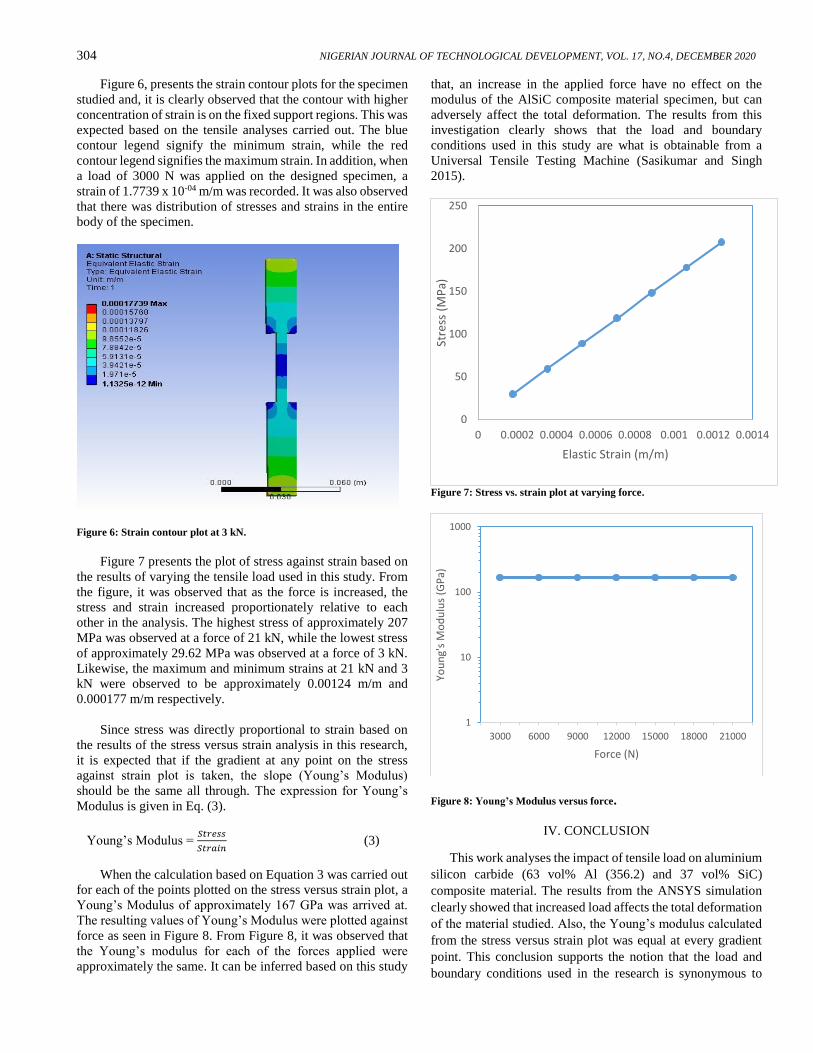
Figure 7 presents the plot of stress against strain based on
the results of varying the tensile load used in this study. From
the figure, it was observed that as the force is increased, the
stress and strain increased proportionately relative to each
other in the analysis. The highest stress of approximately 207
MPa was observed at a force of 21 kN, while the lowest stress
of approximately 29.62 MPa was observed at a force of 3 kN.
Likewise, the maximum and minimum strains at 21 kN and 3
kN were observed to be approximately 0.00124 m/m and
0.000177 m/m respectively.
Since stress was directly proportional to strain based on
the results of the stress versus strain analysis in this research,
it is expected that if the gradient at any point on the stress
against strain plot is taken, the slope (Young’s Modulus)
should be the same all through. The expression for Young’s
Modulus is given in Eq. (3).
Young’s Modulus = 𝑆𝑡𝑟𝑒𝑠𝑠
𝑆𝑡𝑟𝑎𝑖𝑛 (3)
When the calculation based on Equation 3 was carried out
for each of the points plotted on the stress versus strain plot, a
Young’s Modulus of approximately 167 GPa was arrived at.
The resulting values of Young’s Modulus were plotted against
force as seen in Figure 8. From Figure 8, it was observed that
the Young’s modulus for each of the forces applied were
approximately the same. It can be inferred based on this study
that, an increase in the applied force have no effect on the
modulus of the AlSiC composite material specimen, but can
adversely affect the total deformation. The results from this
investigation clearly shows that the load and boundary
conditions used in this study are what is obtainable from a
Universal Tensile Testing Machine (Sasikumar and Singh
2015).
Figure 7: Stress vs. strain plot at varying force.
Figure 8: Young’s Modulus versus force.
IV. CONCLUSION
This work analyses the impact of tensile load on aluminium
silicon carbide (63 vol% Al (356.2) and 37 vol% SiC)
composite material. The results from the ANSYS simulation
clearly showed that increased load affects the total deformation
of the material studied. Also, the Young’s modulus calculated
from the stress versus strain plot was equal at every gradient
point. This conclusion supports the notion that the load and
boundary conditions used in the research is synonymous to
0
50
100
150
200
250
0 0.0002 0.0004 0.0006 0.0008 0.001 0.0012 0.0014St
ress
(M
Pa)
Elastic Strain (m/m)
1
10
100
1000
3000 6000 9000 12000 15000 18000 21000
You
ng'
s M
od
ulu
s (G
Pa)
Force (N)

EKPU: EFFECT OF TENSILE LOAD ON THE MECHANICAL PROPERTIES OF AlSiC COMPOSITE MATERIALS 305
*Corresponding author: [email protected] doi: http://dx.doi.org/10.4314/njtd.v17i4.8
those obtained from UTTM. This research could serve as a
reference material to researchers producing AlSiC composite
materials by stir casting method or process for electronic and
automobile industries.
REFERENCES
Adebisi, A. A. and Ndaliman, M. B. (2016). Investigation
of Analytical Model Development for Processing Aluminum
Silicon Carbide Composite Material. Journal of NIMechE. 6
(1): 71-80.
Adeosun, S. O.; E. I. Akpan and D. Abiodun. (2013). Mould Temperature and Mechanical Properties of Cast
Aluminum-Silicon Carbide Composite. International Journal
of Materials and Chemistry, 3 (4): 75-83.
Agnihotri, R. and Dagar, S. (2017). Mechanical
Properties of Al-SiC Metal Matrix Composites Fabricated by
Stir Casting Route. Research in Medical and Engineering
Sciences. 2 (5): 178-183.
Babalola, P. O.; C. A. Bolu; A. O. Inegbenebor and O.
Kilanko. (2018). Graphical Representations of Experimental
and ANN Predicted Data for Mechanical and Electrical
Properties of AlSiC Composite Prepared by Stir Casting
Method. IOP Conf. Series: Materials Science and Engineering,
413 012063 doi:10.1088/1757-899X/413/1/012063
Ekpu, M.; R. Bhatti; N. Ekere; S. Mallik; E. Amalu and
K. Otiaba. (2011). Investigation of effects of heat sinks on
thermal performance of microelectronic package. 3rd IEEE
International Conference on Adaptive Science and Technology
(ICAST 2011), Abuja, 2011, 127-132, doi:
10.1109/ICASTech.2011.6145164.
Ekpu, M. (2019). Finite Element Analysis of the Effect of
Fin Geometry on Thermal Performance of Heat Sinks in
Microelectronics. Journal of Applied Sciences and
Environmental Management. 23 (11): 2059-2063.
Kumar, S. S.; M. Uthayakumar; S. T. Kumaran; T.
Varol and A. Canakci. (2019). Investigating the surface
integrity of aluminium based composites machined by EDM.
Defence Technology. 15 (3): 338-343.
Meena, K. L.; A. Manna; S. S. Banwait and D. Jaswanti.
(2013). An Analysis of Mechanical Properties of the
Developed Al/SiC-MMC’s. American Journal of Mechanical
Engineering, 1 (1): 14-19.
Nandish, B.; K. P. Muthanna and M. B. Kaveriappa.
(2017). Finite Element Analysis of Aluminium Based
Composite as a Material for Connecting Rod. Applied
Mechanics and Materials, 867 (1): 228-232.
Occhionero, M. A.; R. W. Adams and D. Saums. (2020). AlSiC for Optoelectronic Thermal Management and
Packaging. Last accessed on 26th May 2020.
https://www.researchgate.net/publication/237689513_AlSiC_
for_Optoelectronic_Thermal_Management_and_Packaging_
Designs.
Pawar, P. B. and Utpat, A. A. (2014). Development of
Aluminium Based Silicon Carbide Particulate Metal Matrix
Composite for Spur Gear. Procedia Materials Science, 6
(2014): 1150-1156.
Sasikumar, T. and Singh, R. R. B. (2015). Evaluating the
mechanical characteristics of Al/SiC metal matrix composites
(MMC) using Infrared thermographic Images. 12th
International Conference on Quantitative Infrared
Thermography 2015, July 6-10, Mahabalipuram, India (QIRT
2015): 1-10.
Sujan, D.; C. W. Yeo; M. E. Rahman; M. M. Reddy; M.
A. Maleque and M. Y. Ali. (2012). Aluminum-Silicon
Carbide Composites for Enhanced Physio-Mechanical
Properties. Advance Materials Research, 576 (2012): 370-373.
Teng, F.; K. Yu; J. Luo; H. Fang; C. Shi; Y. Dai and H.
Xiong. (2016). Microstructures and properties of Al−50%SiC
composites for electronic packaging applications. Transactions
of Nonferrous Metals Society of China. 26 (2016): 2647-2652.