

ekofajarcahyadi@st3telkom.acekofajarcahyadi.dosen.st3telkom.ac.id/wp.../02/Pertemuan-7-Sistem...Persyaratan...
39
Transcript of ekofajarcahyadi@st3telkom.acekofajarcahyadi.dosen.st3telkom.ac.id/wp.../02/Pertemuan-7-Sistem...Persyaratan...
OVERVEIEW
In this section we develop a simple point-to-point digital transmission link design considering (Ch8-Keiser): Link power budget calculations and
Link rise time calculations
A link should satisfy both these budgets
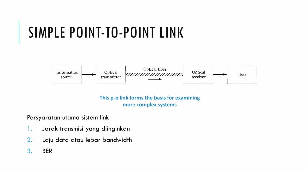
SIMPLE POINT-TO-POINT LINK
Persyaratan utama sistem link
1. Jarak transmisi yang diinginkan
2. Laju data atau lebar bandwidth
3. BER
This p-p link forms the basis for examining more complex systems
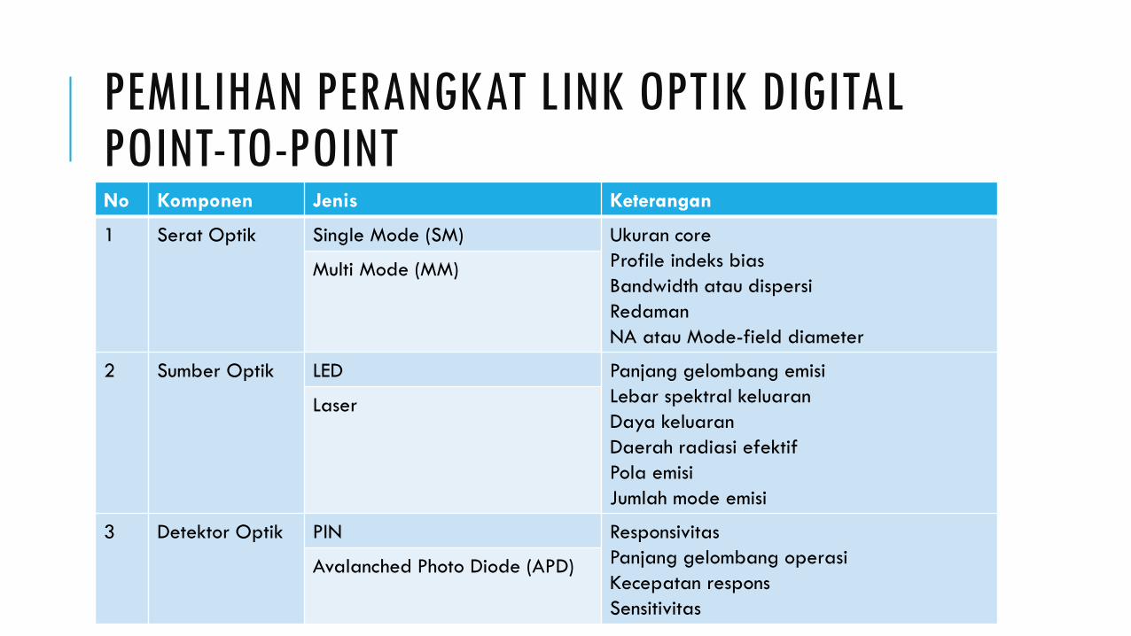
PEMILIHAN PERANGKAT LINK OPTIK DIGITAL POINT-TO-POINTNo Komponen Jenis Keterangan
1 Serat Optik Single Mode (SM) Ukuran core
Profile indeks bias
Bandwidth atau dispersi
Redaman
NA atau Mode-field diameter
Multi Mode (MM)
2 Sumber Optik LED Panjang gelombang emisi
Lebar spektral keluaran
Daya keluaran
Daerah radiasi efektif
Pola emisi
Jumlah mode emisi
Laser
3 Detektor Optik PIN Responsivitas
Panjang gelombang operasi
Kecepatan respons
Sensitivitas
Avalanched Photo Diode (APD)

SYSTEM DESIGN CHOICES: PHOTODETECTOR, OPTICAL SOURCE, FIBERPhotodetectors:
Compared to APD, PINs are less expensive and more stable with temperature. However PINs have lower sensitivity.
Optical Sources:
• LEDs: 150 (Mb/s).km @ 800-900 nm and larger than 1.5 (Gb/s).km @ 1330 nm
• InGaAsP lasers: 25 (Gb/s).km @ 1330 nm and ideally around 500 (Gb/s).km @ 1550 nm. 10-15 dB more power. However more costly and more complex circuitry.
Fiber:
• Single-mode fibers are often used with lasers or edge-emitting LEDs.
• Multi-mode fibers are normally used with LEDs. NA and should be optimized for any particular application.
SELECTING THE FIBER
Bit rate and distance are the major factors
Other factors to consider: attenuation and distance-bandwidth product cost of the connectors, splicing etc.
Then decide
Multimode or single mode
Step or graded index fiber

SELECTING THE OPTICAL SOURCE
•Emission wavelength
•Spectral line width (FWHM) and number of modes
•Output power
•Stability
•Emission pattern
•Effective radiating area
LED
LASER

SELECTING THE DETECTOR
Type of detector
APD: High sensitivity but complex, high bias voltage (40V or more) and expensive
PIN: Simpler, thermally stable, low bias voltage (5V or less) and less expensive
Responsivity (that depends on the avalanche gain & quantum efficiency)
Operating wavelength and spectral selectivity
Speed (capacitance) and photosensitive area
Sensitivity (depends on noise and gain)
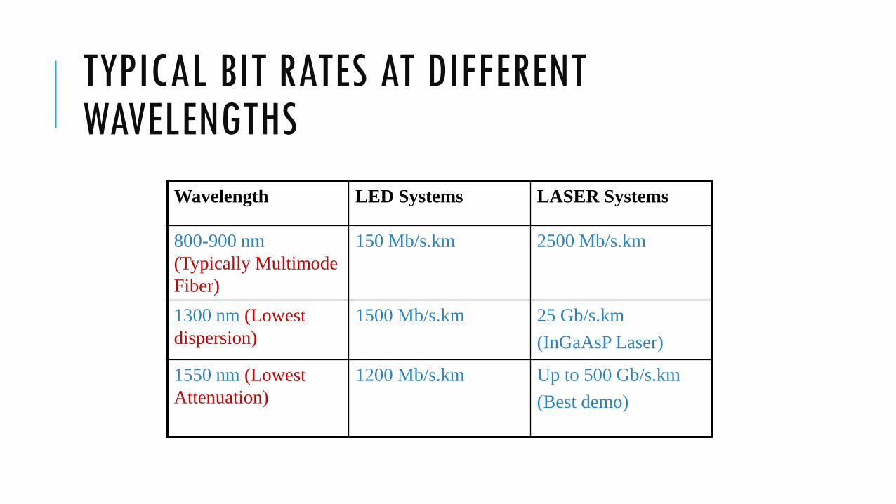
TYPICAL BIT RATES AT DIFFERENT WAVELENGTHS
Wavelength LED Systems LASER Systems
800-900 nm
(Typically Multimode
Fiber)
150 Mb/s.km 2500 Mb/s.km
1300 nm (Lowest
dispersion)
1500 Mb/s.km 25 Gb/s.km
(InGaAsP Laser)
1550 nm (Lowest
Attenuation)
1200 Mb/s.km Up to 500 Gb/s.km
(Best demo)

DESIGN CONSIDERATIONS
Link Power Budget
There is enough power margin in the system to meet the given BER
Rise Time Budget
Each element of the link is fast enough to meet the given bit rate
These two budgets give necessary conditions
for satisfactory operation

RECEIVER SENSITIVITIES VS BIT RATE
Sensitivitas penerima
sebagai fungsi laju
bit

OPTICAL POWER-LOSS MODEL
Keterangan:
𝛼f : Konstanta redaman fiber [dB/Km]
lc : Loss konektor [dB]
lsp : Loss splice [dB]

LINK POWER BUDGET
Loss daya total:
Dimana:
PT : Loss daya total [dBm]
PS : Daya optik dipancarkan dari sumber ujung fiber [dBm]
PR : Sensitivitas detektor [dBm]
m : (Jumlah) konektor
n : (Jumlah) splicer
L : Panjang link [Km]
System margin [dB]
ystem MarginT s R c sp fP P P ml nl L S

EXAMPLE LINK-LOSS BUDGET

LINK POWER BUDGET TABLE
Example:
[SONET OC-48 (2.5 Gb/s) link]
Transmitter: 3dBm @ 1550 nm; Receiver: InGaAs APD with -32 dBm sensitivity @ 2.5 Gb/s;
Fiber: 60 km long with 0.3 dB/km attenuation; jumper cable loss 3 dB each, connector loss of 1 dB each.
Component/loss
parameter
Output/sensitivi
ty/loss
Power margin
(dB)
Laser output 3 dBm
APD Sensitivity @
2.5 Gb/s
-32 dBm
Allowed loss 3-(-32) dBm 35
Source connector
loss
1 dB 34
Jumper+Connecto
r loss
3+1 dB 30
Cable attenuation 18 dB 12
Jumper+Connecto
r loss
3+1 dB 8
Receiver
Connector loss
1 dB 7(final margin)

RISE TIME BUDGET
Untuk menentukan pembatasan dispersi link fiber optic.
Total rise time depends (tsys) on:
Transmitter rise time (ttx)
Group Velocity Dispersion (tGVD)
Modal dispersion rise time (tmod)
Receiver rise time (trx)
Rise time contributor (ti)
1/ 2
2
1
n
sys i
i
t t
Total rise time of a digital link should not exceed
70% for a NRZ bit period, and 35% of a RZ bit period

RISE TIME BUDGET
Umumnya degradasi transition time link digital:•NRZ ≤ 70% perioda bit•RZ ≤ 35% perioda bitRespon front end penerima dpt dimodelkan sbg LPF orde pertama:
Brx : lebar pita elektrik 3 dB dr penerima u(t) : fungsi tangga berharga 1 utk t ≥ 0 dan 0 utk t < 0
Rise time penerima (10 % - 90 %)g(t) :
trx : dlm ns Brx : dlm MHz
PENGKODEAN SALURAN
Format sinyal optis transmisi penting utk dipertimbangkan krn kepraktisan, sirkit decision hrs dpt memisahkan secara tepat informasi timing. Maksud timing : (a) Memungkinkan sinyal disampling pd S/N maks (b) Menjaga spasi pulsa (c) Menunjukan interval start dan stop/end Pengkodean sinyal menggunakan sejumlah aturan utk mengurutkan simbol sinyal dgn pola tertentu. Jenis dasar kode saluran biner dua-level pd trans optik : (a) NRZ (b) RZ (c) Phase Encoded (PE)

KODE NRZ
- Mudah dibangkitkan/dikodekan
- Mudah di-dekodekan
- Tdk memiliki error monitoring atau kemampuan koreksi
- Ttdk memiliki self-clocking (timing)
- Lebar pita minimal
- Daya rata masukan penerima tergantung pd pola data base line wander
- String 1 atau 0 panjang tidak terdapat informasi timing krn tidak ada transisi level.
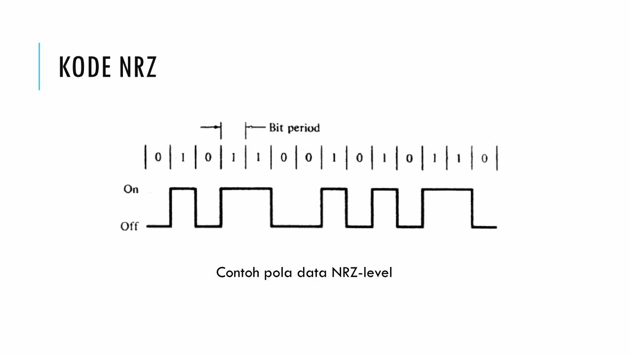
KODE NRZ
Contoh pola data NRZ-level

KODE RZ
- Tiap data bit dikodekan dgn dua bit kode saluran
- Unipolar string 0 panjang akan kehilangan sinkronisasi timing
- Biphase timing dpt diatasi
- Manchester mudah mengkodekan dan dekodekan

KODE RZ
Contoh data format RZ

KODE BLOK
- Kode blok mBnB (n > m) : tiap m bit biner dikodekan dgn n bit biner.
- Peningkatan lebar pita sebesar n/m
- Timing cukup
- Terdpt informasi error minitoring
- Tidak ada string 1 atau 0 panjang tak terjadi base line wander

PERBANDINGAN BEBERAPA KODE MBNB
W : Pesentase n-bit word yg tidak digunakan
Nmax : Jumlah simbol identik berurutan terpanjang
D : Batas disparitas terakumulasi

LATIHAN
Rancangan siskom optik laju data 60 Mb/s sbb : Jarak 60 Km Fiber SM konstanta redaman 0,2 dB/Km, pelebaran pulsa dispersi material 2 ps/Km, panjang kabel 2 Km/haspel. Redaman splice 0,2 dB/bh Redaman konektor 0,5 dB/bh Sumber : daya 1 mW, rise time 5 ns Detektor : sensitifitas – 40 dBm (BER 10-9), rise time 2 ns Margin sistem = 6 dB Selidiki apakah sistem tsb memenuhi anggaran daya ? Selidiki apakah sistem tsb memenuhi anggaran rise time transmisi NRZ dan RZ ? Kesimpulan ?

LATIHAN
Suatu siskom optik memiliki spesifikasi : λ = 1,3 μm trx = 0,35 ns B = 1 Gb/s Dmat = 2 ps/(Km-nm) Fiber SM panjang kabel 2 Km/haspel αf = 0,4 dB/Km lsp = 0,1 dB/bh σλ = 3 nm lc = 1 dB/bh ttx = 0,25 ns Ms = 6 dB Ps = 1 mW Pr = - 42 dBm (BER 10-9) L = 60 Km twg diabaikan Selidiki apakah sistem tsb dpt digunakan utk transmisi dgn line coding RZ dan NRZ ?

RISE TIME BUDGET
MHzin bandwidth receiver is
wherens; 350
rxB
/Bt rxrx
Similarly
txtx Bt /350 ns
Assuming both transmitter and receiver as first order low pass filters

MODAL DISPERSION RISE TIME
Bandwidth BM(L) due to modal dispersion of a link length L is empirically given by,
B0 is the BW per km (MHz-km product) and q ~0.5-1 is the modal equilibrium factor
q
oM LBLB /)(
(ns) /440/44.0 0mod BLBt q
M

GROUP VELOCITY DISPERSION
LDtGVD ||
Where,
D is the dispersion parameter (ns/km/nm) given by eq. (3.57)
σλ is the half power spectral width of the source (nm)
L is the distance in km
LDtGVD ||

TOTAL RISE-TIME
2/12
222
2
0
2
2/1222
mod
2
350440
][
rx
q
tx
rxGVDtxsys
BLD
B
Lt
ttttt
source theof width Spectral :[nm] Dispersion:)]./([
dispersion velocity group todue time-rise :[ns] 7.0
fiber; theof km 1 theof :][fiber theofLength :][BW Electrical 3dB:][
dispersion modal :][ timerisereceiver :][ timeriseer transmitt:][
0
mod
nmkmnsD
tq
BWMHzBkmLMHzB
ntnstnstxt
GVD
rx
rx

EXAMPLE: TRANSMISSION DISTANCE FOR MM-FIBER
NRZ signaling, source/detector: 800-900 nm LED/pin or AlGaAs laser/APD combinations. ; LED output=-13 dBm;fiber loss=3.5 dB/km;fiber bandwidth 800 MHz.km; q=0.7; 1-dB connector/coupling loss at each end; 6 dB system margin, material dispersion ins 0.07 ns/(km.nm); spectral width for LED=50 nm. Laser ar 850 nm spectral width=1 nm; laser ouput=0 dBm, Laser
system margin=8 dB;
910BER

PARAMETERS FOR FIG 8-5
Power coupled
from LED : -13
dBm
Fiber loss 3.5
dB/km
System Margin 6
dB, couplers 1dB
(LED-PIN)
Dmat = 0.07
ns/(nm.km)
LED 50 nm
LASER 1 nm
Bo=800 MHz-km
q = 0.7 (modal)
Power coupled
from LASER = 0
dBm
Material
dispersion limit
with LASER is
off the graph
System Margin 8
dB (Laser-APD)
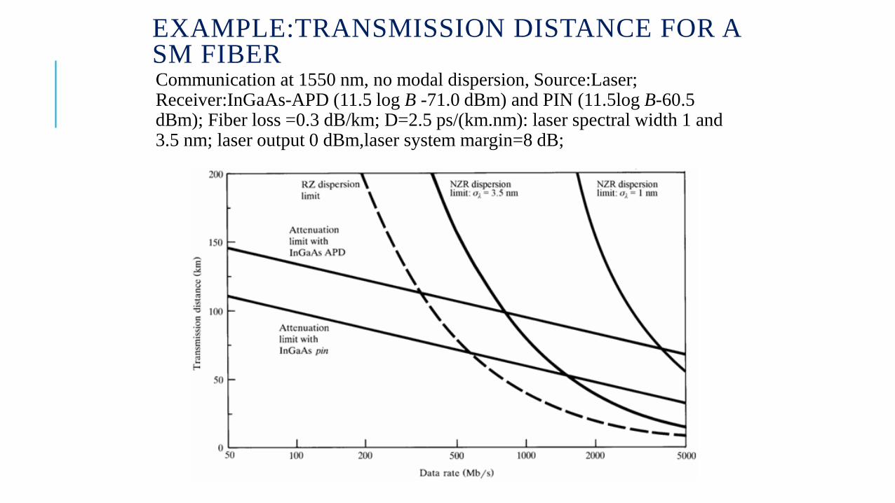
EXAMPLE:TRANSMISSION DISTANCE FOR A SM FIBERCommunication at 1550 nm, no modal dispersion, Source:Laser; Receiver:InGaAs-APD (11.5 log B -71.0 dBm) and PIN (11.5log B-60.5 dBm); Fiber loss =0.3 dB/km; D=2.5 ps/(km.nm): laser spectral width 1 and 3.5 nm; laser output 0 dBm,laser system margin=8 dB;

TWO-LEVEL BINARY CHANNEL CODES

SYSTEM RISE-TIME & INFORMATION RATE
In digital transmission system, the system rise-time limits the bit rate of the system according to the following criteria:
periodbit RZ of %35
periodbit NRZ of %70
sys
sys
t
t
EXAMPLE
Laser Tx has a rise-time of 25 ps at 1550 nm and spectral width of 0.1 nm. Length of fiber is 60 km with dispersion 2 ps/(nm.km). The InGaAs APD has a 2.5 GHz BW. The rise-time budget (required) of the system for NRZ signaling is 0.28 ns whereas the total rise-time due to components is 0.14 ns. (The system is designed for 20 Mb/s).

ANALOG COMMUNICATION LINKS
Analog (RF) links are used in
Analog TV and audio services (Legacy)
Cable modem services
Satellite base stations

MULTI CHANNEL SYSTEMS
Number of RF carriers can be summed and
directly modulate the laser
MULTI CHANNEL SYSTEMS
These have the capability to multiplex several RF channels
Each RF channel is independent, it may carry different type of data (analog video, digital video, digital audio etc.)
The data could be modulated onto the RF carrier using different techniques (AM, FM, QAM etc.)
Nonlinearity is the major concern