
EHV Cable System Standard - TasNetworks · Page 3 of 28 EHV Cable System Standard Record of...
30
Tasmanian Networks Pty Ltd (ABN 24 167 357 299) Standard Extra High Voltage (EHV) Cable System Standard R565986 Version 2.0, June 2018
Transcript of EHV Cable System Standard - TasNetworks · Page 3 of 28 EHV Cable System Standard Record of...
Tasmanian Networks Pty Ltd (ABN 24 167 357 299)
Standard
Extra High Voltage (EHV) Cable System Standard
R565986
Version 2.0, June 2018

Tasmanian Networks Pty Ltd (ABN 24 167 357 299)
AuthorisationsAction Name and title DatePrepared by Michael Verrier, Senior Asset Strategy Engineer June 2018
Reviewed bySantosh Dhakal, Asset Engineer June 2018
Authorised by Darryl Munro, Asset Strategy Team Leader June 2018Review cycle 30 months
ResponsibilitiesThis document is the responsibility of the Asset Strategy Team, Tasmanian Networks Pty Ltd, ABN 24 167 357 299 (hereafter referred to as "TasNetworks") .
Please contact the Asset Strategy Leader with any queries or suggestions.
• Implementation All TasNetworks staff and contractors.
• Compliance All group managers.
Minimum RequirementsThe requirements set out in TasNetworks ’ documents are minimum requirements that must be compliedwith by all TasNetworks team members, contractors, and other consultants.
The end user is expected to implement any practices which may not be stated but which can be reasonablyregarded as good practices relevant to the objective of this document.
© Tasmanian Networks Pty Ltd 2014

Page 3 of 28
EHV Cable System Standard
Record of revisionsSection number Details
Entire doc Copied over verbatim from superseded Transend to TasNetworks template.Updated Transend to TasNetworks document reference numbers where known.
Authorisations Review cycle changed from 60 months to 30 months.
Page 4 of 28
EHV Cable System Standard
Table of contentsAuthorisations...............................................................................................................................................2
Responsibilities............................................................................................................................................. 2
Minimum Requirements...............................................................................................................................2
List of tables..................................................................................................................................................6
1.....................................................................................................................................................General8
1.1..................................................................................................................................Purpose8
1.2..........................................................................................................................................Scope8
1.3................................................................................................................................Objective8
1.4............................................................................................................................ Precedence8
1.5............................................................................................................................. References9
1.5.1.......................................................................................................International standards9
1.5.2.......................................................................................................TasNetworks standards9
1.5.3........................................................................................................TasNetworks drawings9
1.6..................................................................................................................................Glossary10
2.............................................................................................................................. General requirements11
2.1...................................................................Data for asset management information system11
2.2.........................................................................................................................Cable systems11
2.3..............................................................................................................................Civil works11
2.4..................................................................................................................................Earthing11
2.5..................................................................................................................Service conditions11
2.6.......................................................................................................................... Performance11
Page 5 of 28
EHV Cable System Standard
3............................................................................................................................Extra high voltage cable12
3.1........................................................................................Manufacturing plant requirements12
3.2.............................................................................................................................Spare parts13
3.3...............................................................................................................................Packaging14
3.4.................................................................................................General design requirements14
3.5.........................................................................................Design parameters for EHV cables15
3.6..............................................................................Design parameters for optical fibre cable16
3.7...................................................................................................................Cable accessories16
3.8..........................................................................Design requirements for cable terminations17
3.9.....................................................Design requirements for optical fibre underground cable18
3.10..........................................................................................................Joint bay construction18
3.11.........................Design requirements for optical fibre for distributed temperature sensing18
3.12................................................................................... Design requirements for cable joints18
3.13..................................................Design requirements for road crossings and intersections19
3.14...................................... Design requirements for cable installation along road easements20
4................................................................................................................................................... Labelling21
5......................................................................................................................... Installation requirements21
5.1.................................................................................................................................. General21
5.2........................................................................................................ Installation of EHV cable22
5.3.....................................................................................................................Road easements23
5.4..................................................................................................... Cable joints and joint bays23
Page 6 of 28
EHV Cable System Standard
5.5........................................................................................................................... Optical fibre24
5.6.................................................................................................................Cable route survey24
5.6.1..............................................................................................................Survey information24
5.6.2..................................................................................................................Survey drawings25
6......................................................................................................................................................Testing25
6.1...............................................................................................................................Type tests25
6.2..........................................................................................................................Routine tests26
6.3........................................................................................................................... Special tests26
6.4.......................................................................................... Site and pre-commissioning tests26
6.5......................................................................................................................Cable link boxes27
7...................................................................................................Information to be provided with tender27
7.1.......................................................................................Maintenance procedures and plans27
7.2.................................................................................................................Instruction manual28
8...........................................................................................................Condition based risk management29
9...................................................................................................Information to be provided with tender30
9.1......................................................................................................................Cable schedules30
10............................................................................................................................................Deliverables30
List of tablesTable 1................................................................................................Parameters for EHV cable
15
Table 2.......................................................Parameters for optical fibre cable (communication)16
Page 7 of 28
EHV Cable System Standard
Table 3........................................................................................................CBRM requirements29
Page 8 of 28
EHV Cable System Standard
1 General
1.1 PurposeTo define the requirements for ‘Extra High Voltage (EHV) Cable Systems’ under the responsibility of Tasmanian Networks Pty Ltd (hereafter referred to as ‘TasNetworks ’).
1.2 ScopeThis standard contains the requirements for design, engineering, manufacture, construction, testing atmanufacturer’s works, secured packaging, supply, transportation, delivery to site, testing and commissioningwith complete documentation of EHV crosslink polyethylene (XLPE) cables for fixed installations forelectricity supply systems at working voltages of 110 kV and 220 kV and is to be applied to new installationsas well as redevelopment of part or all of existing installations.
1.3 ObjectiveTasNetworks requires the design, manufacture, installation and commissioning of equipment and servicescovered in this standard to:
(a) ensure the relevant Australian legal requirements are met;
(b) ensure the requirements of the National Electricity Rules (NER) are met;
(c) ensure personnel and public safety;
(d) ensure ease in operation and maintenance;
(e) ensure reliability and continuity of power supply to the power transmission network;
(f) support the implementation of TasNetworks’ performance objectives; and
(g) enable customer requirements to be met.
1.1 PrecedenceAny apparent conflict between the requirements of this standard and the law, mandatory requirements,industry standards, project specifications, non-statutory standards or guidelines, and any other associateddocuments should be brought to the immediate attention of TasNetworks for resolution and no action mustbe taken that might result in a breach of law or mandatory standard.
Where there may be a conflict between the requirements of this standard and any:
(a) law, mandatory requirement or industry standard, then that law or statutory requirements will prevailover this standard;
(b) non-mandatory standard, or guideline, then this standard will prevail over that standard or guideline;and
(c) project specification, then the contract documentation will prevail over this standard.
Except that, the selection of equipment, design and all works associated with the EHV cables must conformto the requirements as specified in document R522687, General substation requirements standard.
Approval for a deviation to this standard may only be accorded if it does not reduce the quality ofworkmanship, pose a safety risk to personnel or equipment and does not deviate from the intent of thisstandard. Deviations if any must be specifically requested and approved in writing by TasNetworks’ NetworkPerformance and Strategies Manager.
Page 9 of 28
EHV Cable System Standard
1.1 ReferencesAs a component of the complete specification for EHV cables, this standard is to be read in conjunction withother relevant standards as applicable. Unless otherwise specified in the project specifications, theequipment shall be in accordance with the latest edition and amendments of the standards listed below. Thefollowing documents, without reservation, contain provisions that, through reference in the text, constitutethe requirements of this standard:
1.1.1 International standardsTelecommunication cables – Insulation, sheath and jacket AS 1049
Substation and high voltage installations exceeding 1 kV a.c. AS 2067
Underground marking tape – Non-detectable tape AS 2648
Installation of underground utility services and pipelines within railway boundaries AS 4799
High voltage switchgear and control gear – Dimensional standardization of terminals AS 62271.301
Crossing of waterways by electricity infrastructure AS 6947
Requirements for customer cabling products AS/CA S008
Telecommunication installations – Generic cabling for commercial premises AS/NZS 3080
Electric Cables – Polymeric insulated - For working voltages above 19/33 (36) kV up toand including 87/150 (170) kV
AS/NZS 1429.2
Optical fibres IEC 60793
Optical fibre cables IEC 60794
Power cables with extruded insulation and their accessories for rated voltages above30 kV (Um = 36 kV) up to 150 kV (Um = 170 kV) Test methods and requirements
IEC 60840
1.1.2 TasNetworks standardsR586386 Extra High Voltage System Standard
R590634 Substation Civil Design and Construction Standard
R522687 General Substation Requirements Standard
R579297 Security Fences and Gates Standard
R246497 Testing, Commissioning and Training Standard
R590630 HV and LV Cable System Standard
R522696 Surge Arrestor Standard
R579290 Extra High Voltage Cable Systems - Schedules
R579289 Extra High Voltage Cable Systems - Deliverables
R192947 Excavation Work Standard Ex. D11/12740
R793081 Excavation Procedure
1.1.3 TasNetworks drawingsTypical Overhead Transmission Line Structures Cable Conduit Layout TSD-SD-808-0087-001
Typical Cable Trench Details (Type A without Conduits) TSD-SD-808-0088-001
Page 10 of 28
EHV Cable System Standard
Typical Cable Joint Bay Arrangement details TSD-SD-808-0089-001
Typical Cable Cross Bonding Diagram TSD-SD-808-0090-001
Typical Joint Bay Retaining Wall and Channel Arrangement TSD-SD-808-0091-001
Typical Highway/River/Railway Crossing Bored Conduit Details TSD-SD-808-0092-001
Typical Cable Trench Details (Type B with Conduits) TSD-SD-808-0093-001
1.2 GlossaryAMIS Asset Management Information System
CBRM Condition based risk management
DTS Distributed temperature sensing
EHV Extra high voltage
FAT Factory acceptance testing
FC Fixed connection
FTB Fluidized thermal backfill
GVM Gross vehicle mass
HDPE High-density polyethylene
MDPE Medium-density polyethylene
VCV vertical tower continuous vulcanising
CCV catenary continuous vulcanising
NER National Electricity Rules
OPGW Optical fibre ground wire
EMF Electro magnetic force
OPUC Optical fibre underground cable
OTDR Optical time domain reflectometry
PVC Polyvinyl chloride
SCADA Supervisory control and data acquisition
RTU Remote terminal unit
SCM Sand cement mixture
SVL Sheath voltage limiters
TEC Tasmanian Electricity Code
UV Ultraviolet
VLF Very low frequency
XLPE Crosslinked polyethylene
MTBF Mean time before failure
Page 11 of 28
EHV Cable System Standard
2 General requirementsProject specific requirements for TasNetworks 110 kV and 220 kV EHV crosslink polyethylene (XLPE) cableand accessories will be listed in the project requirements.
2.1 Data for asset management information systemTasNetworks maintains a comprehensive Asset Management Information System (AMIS) that contains alldesign, test results and condition of all TasNetworks assets. The AMIS also contains maintenance regimes forall assets.
The Contractor must provide information required to maintain the currency of AMIS for the EHV cable/s instandard proformas. TasNetworks will provide the proformas to the Contractor. The proformas are requiredto be populated for both new and decommissioned assets.
The completed proformas must be filled in and submitted to TasNetworks as below:
(a) design information and maintenance regime information, including details of maintenance items, theiraccessibility and the frequency of maintenance for the EHV cable/s must be submitted toTasNetworks before commencing installation; and
(b) information on test results for the EHV cable/s must be submitted prior to commissioning.
2.1 Cable systemsAll link boxes, joint terminations, cables, cable accessories and cable systems associated with EHV cable mustbe in accordance with this document.
2.2 Civil worksAll civil works associated with EHV cable systems must be in accordance with the relevant standards.
2.3 EarthingEarthing of all equipment and works associated with EHV cable systems (including earthing at joint bays)must comply with the requirements of this standard and must employ Sheath voltage limiters (SVL) to limitsheath voltages.
2.4 Service conditionsService condition parameters comprising the particulars of the system are stated in Table 1 of this standard,together with site conditions that may affect the performance of the cable, such as soil thermal resistivity.The assessment of substation and cable route site conditions is the responsibility of the Contractor.
Specific environmental conditions and any specific design, installation, operation or maintenance criteria forparticular works will be stated in the project requirements, such as availability of space and proposedswitchyard layout.
2.5 PerformanceEHV cables, must as a minimum meet or exceed the following performance criteria:
Page 12 of 28
EHV Cable System Standard
(a) The EHV cables and accessories must provide reliable performance and be designed for an intendedservice life of 45 years.
(b) The performance of the EHV cable and its accessories must meet all specified electrical, mechanicaland environmental criteria under both normal and abnormal system conditions, such as rated faultcurrent and duration.
(c) The EHV cable and its accessories must be capable of meeting its rated current-carrying capabilitycontinuously, without reduction to the service life. The continuous rating is not to take into accountany cyclic or intermittent loading that may occur.
(d) The EHV cable and its accessories must be physically separated from existing services, such astelecommunications, water, sewerage and electricity distribution network service provider’sinfrastructure, by at least 1.0 m horizontally and 0.5 m vertically , so as to not interfere with theirexisting function, impose a safety hazard or interfere with the EHV cables function.
(e) The selection of the equipment must be based on the most severe of:
(i) requirements mentioned in this standard;
(ii) project requirements;
(iii) results from system analysis; or
(iv) the requirements as stated in document R522687, General Substation RequirementsStandard.
3 Extra high voltage cable
3.1 Manufacturing plant requirementsManufacturing plant processes must take into consideration TasNetworks’ stipulation that:
(a) plant audits by TasNetworks or its representative may be deemed necessary steps to ensure that thebest manufacturer is chosen for specific project;
(b) the manufacturer must be able to demonstrate at least 5 years experience with similar cable design;
(c) the manufacturer’s plant must be ISO 9001 certified;
(d) the cable insulation must ensure that:
(i) the cable shall be insulated as specified in AS 1429.2;
(ii) only crosslinked polyethylene (XLPE) is used. The semi-conductor polyethylene is not to bestored next to the insulating polyethylene due to cross contamination; and
(iii) dry curing method is to be used in order to reduce the number and size of voids, reducedmoisture content, reduced moisture absorption and increased insulation strength.
(e) triple extruders method is used in the manufacturer of the cable with cross section of 500 sq mm orgreater. This shall be carried out on a vertical tower continuous vulcanising (VCV) or MitsubishiDainichi continuous vulcanising (MDCV) extrusion line. For a conductor with cross sectional area of630 sq mm, catenary continuous vulcanising (CCV) extrusion method shall be used;
(f) the distance between insulator hoppers and extruders must be as close as possible (1 to 2 metres);
(g) the method of joining the phase conductors must be specified when doing a manufacturing run;
(h) incoming materials used in the construction of the cable must:
(i) specify where the copper comes from;
Page 13 of 28
EHV Cable System Standard
(ii) specify purity of the copper;
(iii) provide relevant data sheets on the copper used to TasNetworks ;
(iv) provide samples and records of materials used to TasNetworks ;
(v) provide wafers of the cable at the start and finish of each cable run for inspections of voidsand other microscopic analysis to TasNetworks ;
(vi) ensure that the bond between the semi-conductor and the XLPE compounds are checked andsupplied as reference records of the cable; and
(vii) provide evidence of online diagnostic X-ray being carried out during manufacturing to ensurethe conductor is located in the middle of the insulation.
(i) stipulate the time between the cable being removed from the oven to when the metallic screen isapplied; and
(j) provide certified test type reports on prototype.
3.1 Spare partsThe following spare parts requirements will be applicable:
(a) A comprehensive list of recommended spares is required for the cable systems, including a price foreach item and the expected shelf-life if applicable. The spare parts, if ordered, must be identical in allrespects with similar parts incorporated in the cable and will be submitted to the tests and inspectionsspecified herein wherever applicable. Note that TasNetworks is seeking advice from the manufactureras to what spare parts should be held.
(b) The spares parts are part of the contract and need to be supplied. These included, but are not limitedto:
(i) cable joint terminations;
(ii) cable accessories; and
(iii) cable systems associated with EHV cable.
(c) Manufacturers are required to outline their policy for holding essential spare parts for the life of thecable, i.e. 45 years. Information to be supplied includes:
(i) the policy of holding spares;
(ii) details of what spares are held by the manufacturer;
(iii) the duration spares will be held;
(iv) the facilities to manufacture spares over this time period; and
(v) an assurance that the capability, facilities and any information required to supply andmanufacture spares will be retained by the manufacturer over the life of the cable.
(d) The information provided in response to the above queries will determine whether or not someessential spare parts will be purchased and stored by TasNetworks .
(e) Manufacturers are required to outline their policy for maintaining technical support and servicingcapabilities for the life of the cable, i.e. 45 years.
(f) Spare parts must be packed in long term sealed plastic bags and delivered to the TasNetworks’ store inwooden cases of adequate strength to protect the equipment from damage and the ingress ofmoisture during transport and handling.
(g) Each case must be suitably marked so the contents can be ascertained without it being necessary toopen the case. Case marking must include the purchaser’s contract No. and the mass of the crate.
Page 14 of 28
EHV Cable System Standard
3.1 PackagingPackaging, including cable drums must:
(a) provide adequate protection to minimise the risk of damage to the cable and cable systems duringdelivery;
(b) be suited to the particular methods of delivery and provide protection against damage from allforeseen hazards; and
(c) be suitably marked so the contents can be ascertained without it being necessary to open thepackage. Marking must include TasNetworks’ Contract No. and the mass of the crate.
Details of packaging methods must be submitted to TasNetworks for prior approval.
3.1 General design requirementsDesign and selection of cable sizes and cable types must take into consideration the requirements asmentioned below:
(a) Cables must be suitable for most onerous of:
(i) outdoor installation;
(ii) indoor installation in ducts; or
(iii) exposed to direct sunlight,
(b) Cables must be rated and installed to supply the maximum circuit power as specified in the projectrequirements, taking into account the maximum overload that may occur, without any overheatingand reduction to the service life.
(c) Appropriate de-rating factors must be applied in the cable sizing calculations for factors that aredifferent to the conditions nominated by the cable manufacturer in determining the standard cablecurrent ratings.The de-rating factors must compensate for, without limitation:
(i) the variations in the ambient temperature;
(ii) the soil ambient temperature of 25°C must be utilised for the cable sizing calculations;
(iii) group heating effect;
(iv) depth of underground installation;
(v) cable laying formation; and
(vi) spacing.
(d) The cable over-sheath must be designed to withstand the extremely high UV index pertaining toTasmania.
(e) The design of the cable systems must ensure that provision is made for future expansion if required.Such requirements will be defined in the project requirements.
(f) The cable design and design calculations must include, but not be limited to:
(i) conductor size and sheath size calculation;
(ii) cable sheath, single or double point bonding system;
(iii) voltage rise under normal and fault conditions for single, double and cross bonding;
(iv) type of installation, (e.g. in ground: direct buried/conduit/cable trenches/cable ducts; aboveground; cable tunnel);
Page 15 of 28
EHV Cable System Standard
(v) selection of cable route;
(vi) the thermal performance of the cable installation; and
(vii) thermal expansion and contraction.
(g) The Contractor may be made responsible for supplying, delivery, installing and testing sufficient lengthof cable for the circuit requirements as stipulated in the project requirements. A schematic is to beprovided in the project requirements detailing the typical design of a joint bay, including an allowancefor a sufficient length of cable for termination and joints (includes provision for sufficient length ofcable for possible future fault repairs). A schematic is also to be provided in the project requirementsdetailing the typical design for a spare loop of cable to facilitate any minor route deviations requireddue to site conditions.
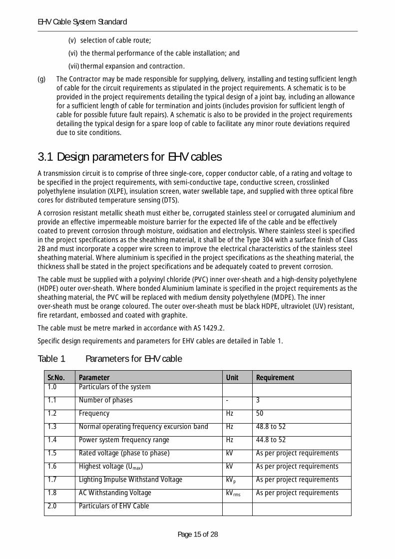
3.1 Design parameters for EHV cablesA transmission circuit is to comprise of three single-core, copper conductor cable, of a rating and voltage tobe specified in the project requirements, with semi-conductive tape, conductive screen, crosslinkedpolyethylene insulation (XLPE), insulation screen, water swellable tape, and supplied with three optical fibrecores for distributed temperature sensing (DTS).
A corrosion resistant metallic sheath must either be, corrugated stainless steel or corrugated aluminium andprovide an effective impermeable moisture barrier for the expected life of the cable and be effectivelycoated to prevent corrosion through moisture, oxidisation and electrolysis. Where stainless steel is specifiedin the project specifications as the sheathing material, it shall be of the Type 304 with a surface finish of Class2B and must incorporate a copper wire screen to improve the electrical characteristics of the stainless steelsheathing material. Where aluminium is specified in the project specifications as the sheathing material, thethickness shall be stated in the project specifications and be adequately coated to prevent corrosion.
The cable must be supplied with a polyvinyl chloride (PVC) inner over-sheath and a high-density polyethylene(HDPE) outer over-sheath. Where bonded Aluminium laminate is specified in the project requirements as thesheathing material, the PVC will be replaced with medium density polyethylene (MDPE). The innerover-sheath must be orange coloured. The outer over-sheath must be black HDPE, ultraviolet (UV) resistant,fire retardant, embossed and coated with graphite.
The cable must be metre marked in accordance with AS 1429.2.
Specific design requirements and parameters for EHV cables are detailed in Table 1.
Table 1 Parameters for EHV cable
Sr.No.Sr.No.Sr.No.Sr.No. ParameterParameterParameterParameter UnitUnitUnitUnit RequirementRequirementRequirementRequirement1.0 Particulars of the system
1.1 Number of phases - 3
1.2 Frequency Hz 50
1.3 Normal operating frequency excursion band Hz 48.8 to 52
1.4 Power system frequency range Hz 44.8 to 52
1.5 Rated voltage (phase to phase) kV As per project requirements
1.6 Highest voltage (Umax) kV As per project requirements
1.7 Lighting Impulse Withstand Voltage kVp As per project requirements
1.8 AC Withstanding Voltage kVrms As per project requirements
2.0 Particulars of EHV Cable

Page 16 of 28
EHV Cable System Standard
2.1 Number of phase per cable - 1
2.2 Rated MVA MVA As per project requirements
2.3 Maximum rated conductor temperature ºC 90
2.4 Maximum emergency conductor temperature ºC 105
2.5 Maximum conductor temperature during faultcurrent
ºC 250
2.6 Maximum fault current kA 40
2.7 Fault current duration s 1
2.8 Short term overload rating (4hrs) MVA As per project requirements
2.9 Nominal Depth to top of cable m 1
2.10 Nominal cable separation mm 300
2.11 Maximum sheath standing voltage V 250
2.12 Conductor cross section mm2 As per project requirements
2.13 Maximum thermal resistivity of thermalstabilised backfill, when dry
ºC
m/W
1.0
3.2 Design parameters for optical fibre cableThe optical fibre cable requirements and parameters must be read in conjunction with Australian StandardAS/ACIF S008, AS 1049, AS 3080, IEC 60794 and IEC 60793.
The optical fibre cable must be of a water-blocked, single loose tube, non-metallic cable design suitable forpower or umbilical cables in short or long haul applications.
Specific design requirements and parameters for optical fibre cables are detailed in Table 2.
Table 2 Parameters for optical fibre cable (communication)
Sr.Sr.Sr.Sr. No. No. No. No. ParameterParameterParameterParameter UnitUnitUnitUnit RequirementRequirementRequirementRequirement1.0 Maximum optical loss dB/km ≤ 0.3 at 850nm
1.1 Maximum splice loss dB/km 0.2
1.2 Minimum bending radius (under load) mm 60
1.3 Minimum bending radius (no load) mm 30
1.4 Temperature range ºC -40 to 70
1.5 Maximum crush resistance kN/mm 1.0 kN/100 mm
1.6 Impact Kg/m 0.25 kg/1.0 m
3.3 Cable accessoriesEach EHV cable’s accessories shall comprise as a minimum:
(a) cable sealing ends;
(b) cable termination kits and palm terminals;
Page 17 of 28
EHV Cable System Standard
(c) surge arrestors;
(d) surge counters;
(e) earthing cables;
(f) earth mat conductor;
(g) prefabricated cable joints suitable for joining of power cable and splicing DTS optical fibre cores;
(h) sheath voltage limiters (SVL);
(i) all bonding leads and cabling;
(j) earth disconnecting link boxes, for use at substations and terminations;
(k) cross-bonding link boxes with SVL, for use at cable joints;
(l) support structures and cross-arms;
(m) 24 core, single mode, optical fibre underground cable (OPUC), with blue sheath;
(n) 40 mm diameter, white conduit for OPUC (only to be corrugated on short runs of 10 m or less andcorners);
(o) optical fibre joint boxes and splicing kits for OPUC;
(p) conduit, for use at road crossings;
(q) concrete and steel mesh reinforcing material, as required; and
(r) stabilised thermal backfill, as required.
3.1 Design requirements for cable terminationsCable termination must comply with the following requirements:
(a) the cable terminations comprise outdoor composite cable sealing ends with a primary line terminalcompliant with AS 62271.301;
(b) surge arrestors (diverters) are required at cable terminations as per Surge Arrestor Standard,R522696. One surge counter per cable, visible and readable from ground level, must be supplied andinstalled for each surge arrestor;
(c) a spare loop shall be provided at each termination and joint bay to allow re-termination in the eventof damage to sealing ends and joints;
(d) within substations, the three terminations are to be supported by separate independent structuralsteel supports that maintain the minimum ground safety clearance as specified by AS 2067. Surgearrestors are to be supported by the same structural steel supports as for the cable’s sealing end.Galvanised steel cable guards are to be utilised to protect the cable from solar radiation, together withcable cleats to support the cable;
(e) at termination structures, the three single-core cable terminations and associated surge arrestors areto be mounted on a transition pole. A steel construction supporting the cable’s sealing ends and surgearrestors is to be at a minimum height of 10 m above ground if outside the perimeter fencing of thesubstation or of sufficient height within the boundary of the substation perimeter fence so as tomaintain safe electrical clearances at all times. Galvanised steel cable guards are to be utilised toprotect each cable, surge arrestors earthing leads, sheath bonding leads and optical fibre ground wire(OPGW) cables to a minimum height of 6.0 m above ground and to the base of the concretefoundations;
(f) the cable guards are to be sized and arranged to allow for natural ventilation and not impair thethermal performance of the EHV cable; and
Page 18 of 28
EHV Cable System Standard
(g) cable cleats installed at a maximum interval of 1.0 m are to be used to support the EHV cable, leadsand OPGW.
3.1 Design requirements for optical fibre underground cableOptical fibre underground cable (OPUC) is required for provision of dedicated bearers for Supervisory controland data acquisition (SCADA), tele-protection and telecommunications associated with the transmissionsystem. Metallic pilot cables are not to be installed within EHV cable trenches for this purpose.
OPUC must comply with the following requirements:
(a) a 24 core, single-mode, loose tube OPUC with blue sheath is required to be supplied and installedwithin a 40 mm minimum diameter, white conduit within the same cable trench as the EHV cable at adepth of 750 mm. The OPUC must be installed directly underneath the cable protection;
(b) at substation terminations, the OPUC is to continue into the control building without any additionalsplicing and all 24 cores are to be terminated to fixed connection (FC) connectors mounted within anoptical fibre termination box within the building; and
(c) where the transmission circuit comprises an associated overhead transmission line section, the OPUCshall be supplied with suitable length to permit splicing to an associated OPGW. The OPUC/OPGWsplice is to be waterproof and contained within a PVC termination joint box situated on thetermination structure. The installation must be sufficiently sized to allow spooling of at least 10 m ofexcess OPUC to allow for re-splicing and joint box maintenance.
3.1 Joint bay constructionJoint bay construction must comply with the following requirements:
(a) joint bay construction must have a similar design as illustrated in the typical joint bay construction diagram TSD-SD-808-0089-001; and
(b) detailed joint bay construction designs must be submitted to TasNetworks for approval at tenderstage.
3.1 Design requirements for optical fibre for distributedtemperature sensing
Optical fibre for distributed temperature sensing (DTS) must comply with the following requirements:
(a) where stainless steel is used as the metallic sheath, three multi-mode optical fibre cores for DTS are tobe supplied and arranged in a single bundle embedded within each EHV cable’s copper wire screen. Incase of corrugated aluminium metallic sheath, the three multi-mode optical fibre cores for DTS are tobe supplied and arranged in a single bundle enclosed within a stainless steel tube embedded insidethe power cable and suitable jelly shall be filled between the tube and optical fibres.
(b) cores are required to be spliced at each cable joint to form continuous lengths of multi-mode opticalfibre; and
(c) at least one optical fibre per EHV cable is to be terminated with fittings at each end suitable for DTS.
3.1 Design requirements for cable jointsCable joints must comply with the following design requirements:
Page 19 of 28
EHV Cable System Standard
(a) EHV cable jointing is permitted if the total length of the cable is greater than 600 m. Where cablejoints are required in the EHV cable, the section lengths are to be no greater than 1000 m, with thetotal length of cable divided into roughly even lengths. TasNetworks must be advised of the plannednumber of joints and arrangement prior to installation;
(b) prefabricated EHV cable joints shall be used. Joints and associated sheath link boxes are to bematched for all three phases in the same transmission circuit so that all cable joints are installed in thesame joint bay in an arrow formation. Link boxes are to be of stainless steel construction;
(c) cross-bonding and transposition at each cable joint are to be used to limit sheath voltages. In addition,the optical fibres for DTS are to be spliced within each joint. EHV cable in flat formation are to betransposed as close as possible to each cable joint with the cable segregation of 300 mm betweencentres being maintained during the transposition. The top of the cables during transposition and thetop of the joints is to be a minimum of 1.0 m below the ground surface;
(d) the joint bay is to be designed and installed to facilitate cable jointing in a clean, dry environment, withan earthed reinforced concrete base and side walls. EHV cables are to be supported, level and straightwithin the joint bay and clamped as appropriate to ensure the cable is secure. A typical joint baydrawing, including sufficient length of cable to allow for termination, a spare loop at terminations,jointing and any minor route deviations that may be made due to site conditions will be provided inthe project requirements. To optimise project efficiency cable joint bays are to be constructed prior tocable installation. Joint bays are not to be installed in 1in100 year flood plains;
(e) If the cable route selection cannot avoid being installed in flood plains then the joint bay must beconstructed such that it is able to maintain water tightness when subjected to a minimum head of 2 mof water above joint bay. Test reports must be provided to verify that joint bays installed in thesepositions are able to satisfy this requirement;
(f) after jointing, cross-bonding and testing, the joint bay is to be filled with the thermal stabilised backfillto a depth of 250 mm above the top of each joint after compaction. At a depth of 750 mm, cableprotection comprising heavy-duty PVC strips (5 mm thick) above each single-core cable joint isrequired. The strips are to overlap each cable by at least 40 mm. The remainder of the fill is to besieved, clean original trench soil, well compacted and consolidated; and
(g) accessible link boxes are to be provided to facilitate cross-bonding of the cable sheaths, together withinternal and ongoing testing of each cable sheath at each joint bay. The link boxes, associated lids andcable entries are to be designed and installed to prevent ground and surface water ingress in both rainand flood conditions. Lids (Gatic) are to be capable of supporting 20 T vehicular loads. The cablesheaths are to be connected via insulated, continuous cross-bonding leads, together with copper barwithin the cross-bonding link box. SVL are to be installed within the link box.
3.1 Design requirements for road crossings and intersectionsEHV cables road crossings and intersections must comply with the following installation and designrequirements:
(a) horizontal directional drilling (boring) is preferred for road crossings and intersections (rivers, creeksrailway tracks, etc) with separated and appropriately sized orange High Density Polyethylene (HDPE)conduits, orange in colour, for each EHV cable phase and a separate HDPE conduit for the optical fibrecable. TasNetworks will consider trenching for minor crossings subject to a written request prior toaward of the contract;
(b) where horizontal directional drilling is used, there is no marker tape or any other type form ofmechanical protection other than the conduits. For safety, the conduit used in horizontal directionaldrilling must have the following clearly legible warning printed in indelible ink at regular intervals sothat the conduit and cable are easily identifiable:
“TASMANIAN NETWORKS
Page 20 of 28
EHV Cable System Standard
Danger power cable”
(c) heavy duty HDPE conduits are to be installed under the road for each cable at least 1.0 m below theroad surface, or alternatively, 1.0 m below the surrounding ground surface, where the road has beenbuilt on fill;
(d) crossing of waterways must comply with the requirements of AS 6947. The depth of the directionaldrilling under river beds must take into consideration, but not limited to, the following criteria:
(i) the thermal resistivity of the soil;
(ii) the expected maximum scouring that may occur in that particular area;
(iii) the depth of sediment that may occur in that particular area; and
(iv) the uplift of the conduit.
The Contractor must source the information pertaining to river scouring from the relevant governmentdepartment;
(e) crossings of railway tracks must comply with the requirement of AS 4799. Where directional drilling isrequired for railway tracks the depth of the directional drilling must be such that the cable is notaffected by vibrations imparted by train movements. The Contractor must acquire the relevantinformation required for directional drilling beneath railway tracks from the relevant Governmentdepartment;
(f) the installation must be designed to take into account the expected vehicular traffic and loading thatmay occur over the design life of the cable installation. Typically the design should cater for aminimum gross vehicle loading capacity of 40 tonnes and an axle loading of 10 tonnes;
(g) the maximum amount of space (fill factor) that the installed cable/s should occupy in a given sizeconduit, expressed as a percentage of the interior volume must not exceed 53 per cent. A minimumspacing of 300 mm must be provided between conduit centres;
(h) HDPE conduit sections are to be joined together with HDPE welds and PVC conduit sections are to bejoined together with PVC cement. Conduit ends are to be capped to prevent entry of water prior tocable installation. The conduit ends are to be continued at least 3.0 m either side of the carriageway;
(i) conduit bends are to be sweeping bends;
(j) the conduit interior, entry and exit points are to be cleaned and free of debris and burrs. No debris isto enter the conduits during cable installation;
(k) all conduit ends to be ‘bell’ ends; and
(l) conduit ends are to be sealed with an approved material.
3.1 Design requirements for cable installation along roadeasements
EHV cables installation along road easements must comply with the following installation requirements:
(a) where EHV cables are installed in parallel with roads, EHV cables are to be direct buried. Alternativemethods of installation may be considered by TasNetworks prior to the award of the contract shouldtraffic volumes or other installation issues be identified by the Contractor;
(b) after cable installation, the road base, road surface and surroundings are to be restored to theiroriginal condition.
Page 21 of 28
EHV Cable System Standard
4 LabellingThe labelling of EHV cables must comply with the following requirements:
(a) cables are to be identified and meter marked in accordance with AS 1429.2;
(b) every drum of cable shall be durably branded , stencilled or labelled on the outside of the flange inaccordance with AS 1429.2;
(c) following installation, respective permanent labelling (red, white, blue) of each EHV cable andcross-bonding leads is to be provided at cable terminations, joints and link boxes to assist in phaseidentification, testing, commissioning and maintenance;
(d) the cables must be additionally protected from future excavations by placing and identificationelectrical cable marker tape over the full width of the cables, comply with AS 2648. The marker tapemust:
(i) be installed at a 300 mm depth, above each single core cable or joint;
(ii) be a continuous length and orange in colour;
(iii) be positioned at 50 per cent of the distance between the mechanical protection and thesurface but, however must not be more than 450 mm above the mechanical protection;
(iv) be lettered with “WARNING”, or “DANGER ELECTRICAL CABLE” or similar wording; and
(v) faithfully follow the route of the cable.
(e) approved surface markers are to be provided to indicate the position of the cables (TasNetworks toapprove surface markers prior to award of contract);
(f) surface markers are to be installed at distances between consecutive markers at the lesser of 50–100m or line of sight, at each deviation/direction change of the cable, at both ends of road crossings, ateach end of joint bays. Where a cable is installed under a road, the surface markers are to be installedon a vertical edge of concrete gutters for ease of visibility and must be affixed to the concrete by bolts,rivets or other similar means. Glue as the sole means of affixing the label will not be permitted.Where cables are installed in rural and peri-urban environments, the label should be affixed to agalvanised steel fencing post (typically 40 mm), extending a minimum of 800 mm above the ground, tothe bottom of the marker plate;
(g) as a minimum the markers are to be yellow background in colour and engraved with the following inblack lettering, with dimensions of 750 mm by 100 mm, The marker must be of non-combustiblematerial. The wording on the marker must be legible, permanent, and formed in a non-combustiblemedium:
“TASMANIAN NETWORKS
110 000 volt power cable
laid in this area”
(h) where cables cross railway lines, cable markers must comply with the requirements of AS 4799.
5 Installation requirements
5.1 GeneralAll excavation works must be in compliance with R192947 Excavation Work Standard.
Page 22 of 28
EHV Cable System Standard
Care must be exercised at all times to ensure that no underground infrastructure is damaged during theexcavation process. Excavation must be performed by hand, unless it can be demonstrated with certaintythat no underground services exist.
No excavation work will be permitted that compromises the minimum coverage of the cable. Shouldadditional soil be added, care must be taken that it does not increase the thermal characteristics of the cablesystem installation and therefore decrease the rating of the circuit.
The Contractor is responsible for the repair of any damaged underground infrastructure at the Contractor’scost, including provision of any temporary bypass services.
5.2 Installation of EHV cableThe installation of EHV cables must comply with the following requirements:
(a) the cables are to be direct buried 1.0 m below the ground surface, preferably in flat formation withminimum of 300 mm separation between phase centres. Where a limited trench width is required, atrefoil formation with 300 mm separation may be utilised subject to approval from TasNetworks priorto award of contract;
(b) the bottom of the cable trench must be levelled and any gradients or changes in depth must begradual. The trench must be free of loose earth and any stones before the cables are installed. The topof each cable is to be a minimum of 1.0 m below the ground surface and the bottom of each cable isto be a minimum 100 mm above the trench base. Thermal stabilised backfill is to be utilised to fillunderneath and cover the top of each EHV cable by at least 250 mm after compaction andconsolidation. The thermal stabilised backfill is to be extended to cover both the trench walls with thetrench walls to be filled with at least 100 mm of thermal stabilised backfill to protect the outer cables.To prevent damage to the cable, backfilling must be carried out as soon as possible after the cableshave been installed;
(c) thermal stabilised backfill sand cement mixture (SCM). The SCM must comprise of a sand cementmixture (14:1) and be thoroughly mixed. The thermal resistivity of SCM must be less than 1°Cm/W at1.0 per cent moisture content. Compaction is to be achieved by a hand held mechanical compactor;
(d) the remainder of the trench is to be filled with native sieved clean soil that is friable, free of any wastematerial and sharp rocks, then well compacted and consolidated. This friable clean soil may beobtained from sieved original trench soil if tested results indicate that the thermal resistivity is lessthan 1.2 °C m/W at 1 per cent moisture content. Excess original trench soil, rocks and waste are to beremoved and disposed by approved methods;
(e) the exception to direct buried installation method is for road crossings, where conduits are utilised.Where future requirements necessitate provision to be made for the installation of additional cables,conduits may be considered subject to approval from TasNetworks ;
(f) protection from direct solar radiation is to be provided where the cable is above ground;
(g) cable protection, comprising heavy-duty PVC strips (5 mm thick), must be installed at ≤75 mm abovethe top of each single-core EHV cable. The typical width of the heavy-duty strips is 300 mm and mustoverlap by at least 100 mm on each side, however dependent on the installation the heavy-duty PVCstrips may overlap each cable conduit by at least 40 mm subject to approval from TasNetworks ;
(h) cables must be provided with explosion proof link boxes if required by the design;
(i) pulling of EHV cable must use methods and procedures as recommended by the EHV cablemanufacturer;
(j) the EHV cable ends must be sealed at the factory. Each EHV cable section must be equipped withfactory installed ‘pulling eyes’ at both ends;
Page 23 of 28
EHV Cable System Standard
(k) the maximum pulling tension and maximum sidewall force as recommended by the cablemanufacturer must not be exceeded during the process of cable laying;
(l) suitable means, such as pulleys, rollers at bends and proprietary brands of pulling lubricant must beused to reduce friction and tension exerted on the cable. The lubricants must:
(i) be water based;
(ii) be compatible with the cable outer sheath;
(iii) not set or harden during cable installation;
(iv) not set in future; and
(v) not consist of oil or grease.
(m) free running rollers must be positioned on the trench bottom to minimise frictional forces;
(n) rollers used must match the curvature of the EHV cable to ensure that the EHV cable is not damagedor deformed;
(o) skid plates must be installed at bends and maintain a smooth effective curvature not less than thecable installation radius;
(p) the EHV cable minimum bending radius must not be exceeded at any time;
(q) the cable drum must be assisted in turning while pulling the cable during installation and wherenecessary be prevented from being subjected to a reverse bend as the cable comes off the reel;
(r) an acceptable means of mechanical braking must be employed when laying cables in steep terrains;
(s) EMF mitigation techniques; and
(t) TasNetworks has the right to inspect both the EHV cable and joints during installation and prior tobackfilling. Hold points will be stipulated in project requirements.
5.1 Road easementsWhere cable installations impact road easements the following requirements must be satisfied:
(a) road crossings are to be made with a minimum of disruption to traffic;
(b) road easements are required to provide minimum of disruption to traffic access to properties duringtrenching; and
(c) where vehicle access is permitted during trenching, a heavy-duty traffic barrier must be erected.
5.1 Cable joints and joint baysThe following provisos will be applicable for cable joints and joint bays:
(a) all joint bay construction must have a similar design as illustrated in the typical joint bay constructiondiagram TSD-SD-808-0089-001;
(b) the installation will not be accepted if additional in-line joints have been installed due to cable damageor shortfall during supply, installation and testing;
(c) the cable must be snaked to allow for thermal expansion applied to tunnel installation wheresupported on cable rack as illustrated in diagram TSD-SD-808-0089-001; and
(d) if cable damage or shortfall occurs that requires additional in-line joints then the Contractor will berequired to replace the entire cable section.
Page 24 of 28
EHV Cable System Standard
5.1 Optical fibreThe installation of optical fibre must comply with the following requirements:
(a) the splicing to OPGW is to occur at ground level;
(b) a qualified experienced communications officer must perform all splicing of optical fibre utilised fortelecommunications purposes;
(c) a DTS test is required to be performed on the EHV cable immediately after energisation, withsufficient load present, to provide an initial assessment of the cable’s thermal performance; and
(d) the Contractor must supply the DTS software and hardware required for each cable route. Thesoftware must, as a minimum, be able to capture and store the cable temperature over time andenable easy visualization of the circuit’s historical and real time thermal profile. TSP-IP DNP 3.0communications media shall be used to establish connectivity between the DTS hardware device/sand the existing RTU of the substation to enable critical alarms to be integrated into TasNetworks’SCADA system.
5.1 Cable route surveyThe Contractor is responsible for accurately surveying and recording any modifications from the originalmaterial schedules, route and section drawings, including any dimension changes, transpositions, exactlocation of other underground infrastructure and any clearances from existing infrastructure and propertyboundaries. All dimensions must be taken from points that are reasonably expected to remain constant forthe life of the cable.
5.1.1 Survey informationThe survey must provide survey location information of:
(a) the cable at all bends sufficient to accurately determine the curvature of the cable. This is to includethe relative level on the top of the protection slab where installed or the top of the conduit or duct,etc. or where direct laid the top of the cable and the natural surface level at these points;
(b) the beginning and end of cable route along a straight section with sufficient points along the route toaccurately determine the cable location;
(c) where the cable is laid in elevated ground line or in-ground troughing, the location of all bends andthe troughing at sufficient intervals to accurately determine the cable location;
(d) any cable pits, manholes etc. and where a change to the configuration of the cable occurs in thetrench. This is to include the relative level at the top of these structures and or the relative level ontop of the protection slab where installed or the top of the conduit or duct etc. and the natural surfaceat these points;
(e) other services which cross the trench, their location, depth and details of the service, e.g. is to berecorded. The depth is to be provided as a relative level on the top of the service, on the cableprotection slab and the natural surface at the location;
(f) where cable routes cross over one another, the location of these intersections and the relative level ofboth cable routes and the natural surface level are to be provided;
(g) locations of any joints in the cable together with the relative level of the protection covering the jointand the natural surface levels at these locations;
(h) where cables pass under tracks, the location of the tracks and a level on the tracks is to be recorded;and
Page 25 of 28
EHV Cable System Standard
(i) the location of other structures and features within 4 metres of the centre line of the cable trench isto be recorded. Examples of other structures and features are transmission line poles, manholes,buildings, and fences etc.
5.1.1 Survey drawingsThe following drawing information must be provided:
(a) cross section of diagrams are to be provided to indicate the configuration of cables in the trench,ducts, troughing, cable pits, tunnels and at points where cables cross;
(b) where cables are in ducts, cross section diagrams are to be provided at both start and finish of theducts. The cross sections are to be drawn by looking along the cable route in the direction away fromthe point of supply;
(c) where the cable routes are cross-country the cross sections are to be drawn looking along the cableroute in the direction away from the point of supply;
(d) survey field notes are to be provided with sketches of the area through which the cable route passes;
(e) survey field notes are to be provided with sketches of the area through which the cable passes; and
(f) where the cable is in public roads/footways a schematic showing the location of the kerb lines, streetcorners and building lines must be provided on the side of the roadway nearest to the cable trench.
Other details such as the date of the survey, the date of the cable installation, general description of thework and details of the cable laid, i.e. voltage, type, size, etc. must be provided.
6 TestingTesting, installation and commissioning must comply with the requirements of the document R246497Testing, Commissioning and Training standard.
All components of EHV cable systems must be duly tested in accordance with relevant applicable Australianand international standards. Where tests are optional in the standards, it will be considered that these testsare required by TasNetworks , unless otherwise requested by Contractor and agreed in writing byTasNetworks before the award of Contract.
All test reports must be forwarded to TasNetworks for approval and acceptance. The tests will be consideredas complete, only after an approval and acceptance of test results is received in writing by TasNetworks . Alist of the tests to be conducted on EHV cable systems is provided below.
6.1 Type testsType tests are intended to prove the soundness of design of the systems and their suitability for operationunder the conditions detailed in Table 1 and therefore must comply with the following requirements:
(a) type tests must be carried out before the delivery of the cable. A certified test report, detailing theresults of such tests along with the procedures followed, must be provided to TasNetworks . Thesetests must have been applied to a system of identical design to that of the tender offer, or on a systemof a design which does not differ from that offered in any way which might influence the properties tobe checked by the type test;
(b) where such tests have already been performed, a copy of type test reports that qualifies for theexemption must be provided with the tender;
(c) type tests for cables as specified in AS 1429.2 will apply for all EHV cables; and
Page 26 of 28
EHV Cable System Standard
(d) where cables are at rated voltages above 145 kV, then TasNetworks may specify any additional typetest requirements.
6.1 Routine testsRoutine tests must comply with the following requirements:
(a) routine tests for cables as specified in AS 1429.2 will apply for all EHV cables;
(b) routine tests must be conducted on the cable to prove quality of manufacture and conformance withthe relevant performance requirements of the applicable standard. The tests must be performed atthe manufacturer’s works prior to delivery;
(c) procedures for routine tests with supporting documentation must be submitted to TasNetworks forapproval and acceptance. Routine tests will not be conducted unless the routine test procedures havebeen accepted and approved by TasNetworks ;
(d) an optical time domain reflectometry (OTDR), attenuation and continuity test from both ends of eachdrum will apply to all optical fibre cores within both EHV cable and OPUC;
(e) where cables are rated at voltages above 145 kV, then TasNetworks may specify additional routinetest requirements;
(f) certified test reports are required as part of the contract; and
(g) routine factory test results must be approved and accepted by TasNetworks prior to dispatch ofequipment to site.
6.1 Special testsSpecial tests must comply with the following requirements:
(a) the special tests must be conducted on the samples of the EHV cable to prove quality of manufactureand conformance with the relevant performance requirements of the applicable standards;
(b) procedures for special tests with supporting documentation must be submitted into TasNetworks forapproval and acceptance. Special tests will not be conducted unless the special test procedures havebeen accepted and approved by TasNetworks ;
(c) sample tests for cables as specified in AS 1429.2 will apply for EHV cable production batch to provequality of manufacture; and
(d) special factory test will only be considered as completed after TasNetworks accepts the test results.
6.1 Site and pre-commissioning testsSite installation and pre-commissioning tests must be conducted on the installed system after erectionon-site and before it is put into service to prove that it has not been damaged during transportation,installation or jointing.
The site test procedures must be submitted to TasNetworks for approval.
Site test reports must be approved and accepted by TasNetworks before placing equipment in service.
As a minimum the tests stated below must be conducted:
(a) soil thermal resistivity and stability test on at least one wet and one dry nominated sample of eachdifferent trench fill material utilised (e.g. thermal stabilised back-fill and friable original soil, free of anywaste material) prior to use;
Page 27 of 28
EHV Cable System Standard
(b) attenuation, OTDR and continuity test on all optical fibre cores within both EHV cables and OPUC,from all cable termination points;
(c) FAT tests on cable link boxes must be submitted to TasNetworks for approval and acceptance;
(d) phasing / continuity check;
(e) over sheath bonding contact resistance measurement where applicable;
(f) 1 kV d.c. over sheath test;
(g) 5 kV insulation resistance test;
(h) high voltage a.c test at power frequency as per AS 1429.2, (note: d.c. testing is not permitted);
(i) very low frequency (VLF) test on new cables between 2.7 and 3.0 times the cable operating voltage(Uo) for 30 minutes;
(j) VLF test on existing or aged cables for recommissioning at a maximum of 2.0 times the cable operatingvoltage (Uo) for 15 minutes;
(k) sheath voltage limiter test;
(l) cable impedance measurement (positive, negative and zero sequence) test; and
(m) cross bonding verification test.
6.1 Cable link boxesCable link boxes must comply with the following requirements:
(a) the cable link boxes must be lockable type, constructed from stainless steel (minimum grade 304)sheet metal panels;
(b) the minimum degree of protection of enclosure for single point bonding cable link boxes must be IP56and for cross bonding link boxes IP 67;
(c) the cable link boxes must be large enough to accommodate clamp-on CTs for partial dischargemonitoring; and
(d) the cross bonded cable link boxes must be covered by a removable lid (Gatic) capable of carrying atrafficable load of 20 tonnes (GVM) and it should be lockable and sealed in a manner to preventmoisture ingress.
7 Information to be provided with tender
7.1 Maintenance procedures and plansTasNetworks will carry out various maintenance tests during the life of the cable. These tests may be part ofa routine preventive and condition based maintenance program and hence be carried out repeatedly atnominal intervals or they may be part of a refurbishment project after an overhaul or repair. TasNetworks’maintenance tests may consist of repeated operational tests and functional checks on the variousprotection, operation and control and indication systems as part of a routine maintenance program. Theequipment offered must therefore be suitable for the repeated application of the various maintenance testsTasNetworks may with to perform during the life of the cable installation.
The contractor must provide:
(a) a detailed maintenance plan, procedures and task guides covering the design life of the equipment;
(b) recommend the frequency for maintenance based on time, operational count, operational events; etc;
Page 28 of 28
EHV Cable System Standard
(c) a recommended routine test plan; and
(d) blank schedules and forms for maintenance and routine testing, for use by TasNetworks maintenancepersonnel.
7.1 Instruction manualThe Contractor must supply to TasNetworks , before the first delivery of the equipment, three copies of aninstruction manual giving all the information necessary for the installation, commissioning, operation andmaintenance of each portion of the equipment.
Each manual shall relate solely to the equipment supplied, and shall not contain any material which is notapplicable to this equipment.
The manuals shall be suitable for accepting A4 size sheets and all drawings shall be suitably folded orphotographically reduced for convenient filing in the manual.
Within three months after the date of an order a draft instruction manual shall be submitted to TasNetworksfor approval. The equipment shall be considered substantially incomplete for the purpose of payment untilthe approved copies of this manual have been received.
Each instruction manual shall comprise the following:
(a) a cover suitable to withstand normal field handling;
(b) a comprehensive index of all material in the manual;
(c) a description of the cable system;
(d) a summary of all electrical parameters and the performance data of the cable system;
(e) calculations of the electrical design, cable ratings and sheath induced voltages;
(f) a general description followed by a detailed technical account of the operation of each portion of theequipment. This shall include the drawings, diagrams, graphs, and photographs needed to ensureclarity;
(g) a copy of each type and routine test certificate and report;
(h) a copy of the results of all tests made after delivery and installation;
(i) a sketch showing thermocouple locations and formulae and graphs to compute the conductortemperature from the serving temperature;
(j) information on the inspection, testing, installation and maintenance of all equipment. This shallinclude:
(i) instructions for installing each item of equipment and material. These shall include detailedcable jointing and terminating instructions;
(ii) the instructions required to dismantle and assemble each item of equipment, whereappropriate;
(iii) a schedule of the tests, adjustments, replacements and other work required to maintaincorrect performance;
(iv) values, with permissible tolerances, to be achieved in the scheduled tests and adjustments;and
(v) any other information that the Contractor considers to be useful or relevant to the particularinstallation.
Page 29 of 28
EHV Cable System Standard
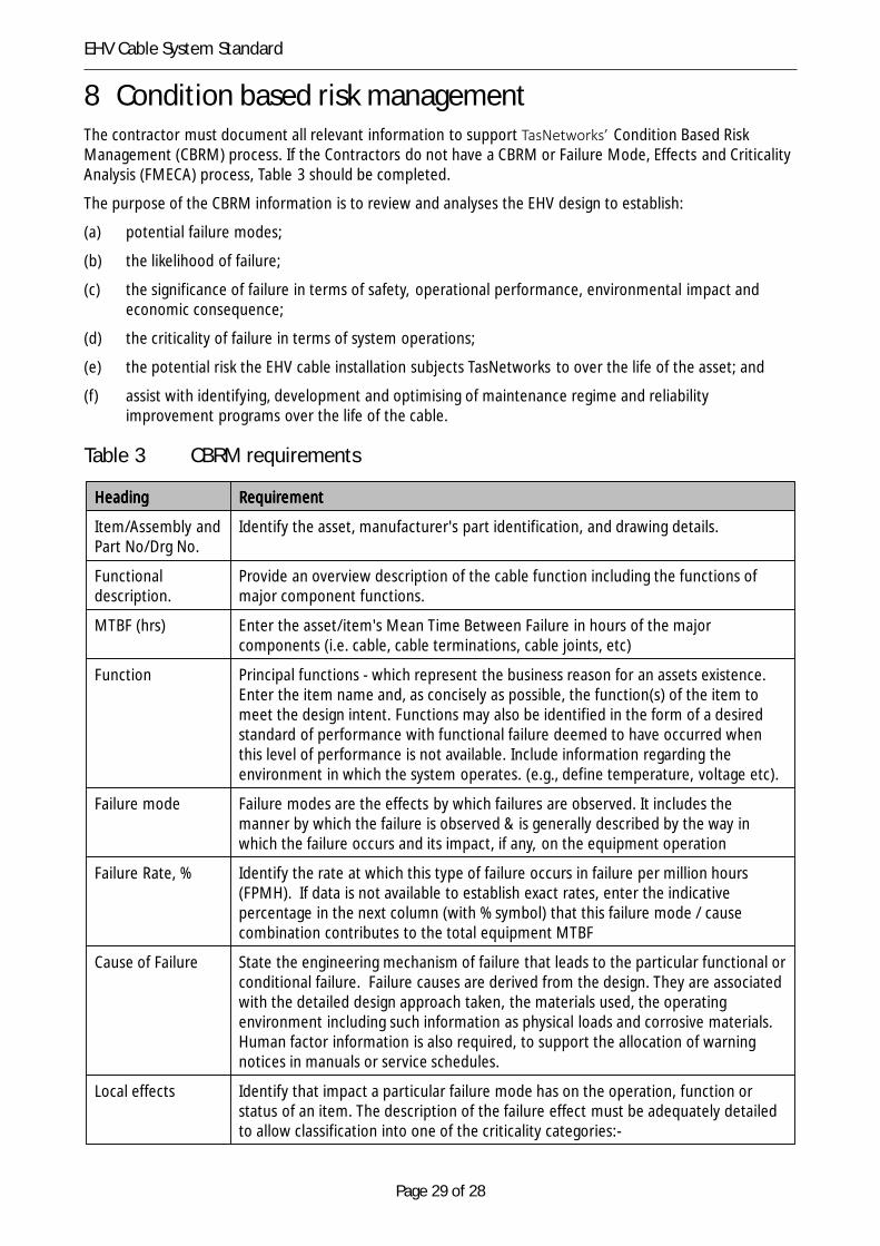
8 Condition based risk managementThe contractor must document all relevant information to support TasNetworks’ Condition Based RiskManagement (CBRM) process. If the Contractors do not have a CBRM or Failure Mode, Effects and CriticalityAnalysis (FMECA) process, Table 3 should be completed.
The purpose of the CBRM information is to review and analyses the EHV design to establish:
(a) potential failure modes;
(b) the likelihood of failure;
(c) the significance of failure in terms of safety, operational performance, environmental impact andeconomic consequence;
(d) the criticality of failure in terms of system operations;
(e) the potential risk the EHV cable installation subjects TasNetworks to over the life of the asset; and
(f) assist with identifying, development and optimising of maintenance regime and reliabilityimprovement programs over the life of the cable.
Table 3 CBRM requirements
HeadingHeadingHeadingHeading RequirementRequirementRequirementRequirement
Item/Assembly andPart No/Drg No.
Identify the asset, manufacturer's part identification, and drawing details.
Functionaldescription.
Provide an overview description of the cable function including the functions ofmajor component functions.
MTBF (hrs) Enter the asset/item's Mean Time Between Failure in hours of the majorcomponents (i.e. cable, cable terminations, cable joints, etc)
Function Principal functions - which represent the business reason for an assets existence.Enter the item name and, as concisely as possible, the function(s) of the item tomeet the design intent. Functions may also be identified in the form of a desiredstandard of performance with functional failure deemed to have occurred whenthis level of performance is not available. Include information regarding theenvironment in which the system operates. (e.g., define temperature, voltage etc).
Failure mode Failure modes are the effects by which failures are observed. It includes themanner by which the failure is observed & is generally described by the way inwhich the failure occurs and its impact, if any, on the equipment operation
Failure Rate, % Identify the rate at which this type of failure occurs in failure per million hours(FPMH). If data is not available to establish exact rates, enter the indicativepercentage in the next column (with % symbol) that this failure mode / causecombination contributes to the total equipment MTBF
Cause of Failure State the engineering mechanism of failure that leads to the particular functional orconditional failure. Failure causes are derived from the design. They are associatedwith the detailed design approach taken, the materials used, the operatingenvironment including such information as physical loads and corrosive materials.Human factor information is also required, to support the allocation of warningnotices in manuals or service schedules.
Local effects Identify that impact a particular failure mode has on the operation, function orstatus of an item. The description of the failure effect must be adequately detailedto allow classification into one of the criticality categories:-
Page 30 of 28
EHV Cable System Standard
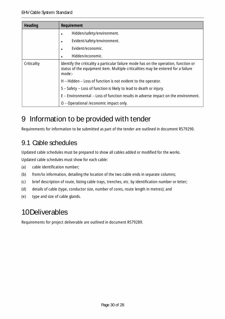
HeadingHeadingHeadingHeading RequirementRequirementRequirementRequirement
• Hidden/safety/environment.
• Evident/safety/environment.
• Evident/economic.
• Hidden/economic.
Criticality Identify the criticality a particular failure mode has on the operation, function orstatus of the equipment item. Multiple criticalities may be entered for a failuremode:-
H – Hidden – Loss of function is not evident to the operator.
S – Safety – Loss of function is likely to lead to death or injury.
E – Environmental – Loss of function results in adverse impact on the environment.
O – Operational /economic impact only.
9 Information to be provided with tenderRequirements for information to be submitted as part of the tender are outlined in document R579290.
9.1 Cable schedulesUpdated cable schedules must be prepared to show all cables added or modified for the works.
Updated cable schedules must show for each cable:
(a) cable identification number;
(b) from/to information, detailing the location of the two cable ends in separate columns;
(c) brief description of route, listing cable trays, trenches, etc. by identification number or letter;
(d) details of cable (type, conductor size, number of cores, route length in metres); and
(e) type and size of cable glands.
10DeliverablesRequirements for project deliverable are outlined in document R579289.