EGP-04-01 - Engineering Drawings and Documentation
26
Division / Business Unit: Safety, Engineering & Technology Function: All Disciplines Document Type: Standard © Australian Rail Track Corporation Limited (ARTC) Disclaimer This document has been prepared by ARTC for internal use and may not be relied on by any other party without ARTC’s prior written consent. Use of this document shall be subject to the terms of the relevant contract with ARTC. ARTC and its employees shall have no liability to unauthorised users of the information for any loss, damage, cost or expense incurred or arising by reason of an unauthorised user using or relying upon the information in this document, whether caused by error, negligence, omission or misrepresentation in this document. This document is uncontrolled when printed. Authorised users of this document should visit ARTC’s intranet or extranet (www.artc.com.au) to access the latest version of this document. Page 1 of 26 Engineering Drawings and Documentation EGP-04-01 Applicability ARTC Network Wide SMS Publication Requirement Internal / External Primary Source Document Status Version # Date Reviewed Prepared by Reviewed by Endorsed Approved 3.2 23 Aug 21 Configuration Management Administrator Configuration Manager Manager Standards Acting GM Technical Standards 23/09/21 Amendment Record Amendment Version # Date Reviewed Clause Description of Amendment 1.0 23 Apr 13 First issue of new Standard to be read in conjunction with new Procedure EGP-04-02. 1.1 21 Feb 14 3.1 More detail added regarding version of AutoCAD files to be supplied for addition to DMS. 1.2 14 Oct 15 Document rebranded 1.3 9 May 16 3.1, 3.2 & 3.6 Further detail added regarding approval of drawings, including addition of approval information on drawing templates
Transcript of EGP-04-01 - Engineering Drawings and Documentation

Division / Business Unit: Safety, Engineering & Technology
Function: All Disciplines
Document Type: Standard
© Australian Rail Track Corporation Limited (ARTC)
Disclaimer
This document has been prepared by ARTC for internal use and may not be relied on by any other party without ARTC’s prior written consent. Use of this document shall be subject
to the terms of the relevant contract with ARTC.
ARTC and its employees shall have no liability to unauthorised users of the information for any loss, damage, cost or expense incurred or arising by reason of an unauthorised user
using or relying upon the information in this document, whether caused by error, negligence, omission or misrepresentation in this document.
This document is uncontrolled when printed.
Authorised users of this document should visit ARTC’s intranet or extranet (www.artc.com.au) to access the latest version of this document.
Page 1 of 26
Engineering Drawings and
Documentation
EGP-04-01
Applicability
ARTC Network Wide
SMS
Publication Requirement
Internal / External
Primary Source
Document Status
Version # Date Reviewed Prepared by Reviewed by Endorsed Approved
3.2 23 Aug 21 Configuration
Management
Administrator
Configuration
Manager
Manager
Standards
Acting GM Technical
Standards
23/09/21
Amendment Record
Amendment
Version #
Date Reviewed Clause Description of Amendment
1.0 23 Apr 13 First issue of new Standard to be read in conjunction with new
Procedure EGP-04-02.
1.1 21 Feb 14 3.1 More detail added regarding version of AutoCAD files to be
supplied for addition to DMS.
1.2 14 Oct 15 Document rebranded
1.3 9 May 16 3.1, 3.2 & 3.6 Further detail added regarding approval of drawings, including
addition of approval information on drawing templates

Engineering Drawings and Documentation
EGP-04-01
Table of Contents
This document is uncontrolled when printed. Version Number: 3.2 Date Reviewed: 23 Aug 21 Page 2 of 26
2.0 17 Nov 17 Various Addition of requirement for combined pdf file of updated
master records included to standardise requirement across all
disciplines and in line with new DMS system requirements.
Addition of note regarding update of drawings when
infrastructure is decommissioned. Also clarification of
requirement for As Commissioned drawings for civil and
structures works and the revision format on drawing templates.
Clarification of the timeframes for supply of drawings. Addition
of naming convention for scanned NSW signal drawings.
3.0 28 Jun 19 2.3, 2.7, 3.1,
3.7 & 5.3
Additional information included regarding scoping and
acceptance of design to section 2.3. Use of standard drawings
added in section 2.7. Minor update to drawing format and
clarification on year of creation in section 3.1 Further detail
added to ARTC acceptance of drawings in section 3.7
Signalling design data references added to section 5.3.
Signalling test files requirements added in new section 5.4 &
project drawings flowchart added in new section 6.
3.1 4 Mar 21 1.5 Addition of request for drawings and signal data submission
forms previously attached to ESI-07-02. Signatures on
drawings clarified to enable acceptance of digital signatures.
3.2 23 Aug 21 1.3, 1.4, 1.5,
2, 4.3
Overview, Definitions & Applicable Documents sections
updated. Drawing Management System requirements for
Public Transport Victoria expanded. Process for updating
marked-up maintenance copies of drawings. Process for
conducting correlations added.

Engineering Drawings and Documentation
EGP-04-01
Table of Contents
This document is uncontrolled when printed. Version Number: 3.2 Date Reviewed: 23 Aug 21 Page 3 of 26
Table of Contents
Table of Contents ............................................................................................................................................. 3
1 Introduction ............................................................................................................................................. 5
1.1 Purpose .......................................................................................................................................... 5
1.2 Procedure Owner ........................................................................................................................... 5
1.3 Overview ........................................................................................................................................ 5
1.4 Definitions ....................................................................................................................................... 6
1.5 Applicable Documents ................................................................................................................... 6
2 Drawing Management Systems ............................................................................................................ 7
2.1 ARTC Drawing Management System ............................................................................................ 7
2.2 Victorian Drawing Management System ........................................................................................ 7
3 Projects / Maintenance Requirements ............................................................................................... 11
3.1 General Requirements ................................................................................................................. 11
3.2 Configuration Management Requirements .................................................................................. 12
3.3 Design Requirements ................................................................................................................... 12
3.4 Commissioning & Testing Requirements ..................................................................................... 13
3.5 Project Completion and Handover Requirements........................................................................ 13
3.6 Managing Drawing Updates for Multiple Simultaneous Works .................................................... 13
3.7 Use of Standard Drawings for Projects ........................................................................................ 14
4 General Requirements ......................................................................................................................... 15
4.1 Drawing Format ............................................................................................................................ 15
4.1.1 Drawing Templates ....................................................................................................................... 15
4.2 Revision of Existing Drawings ...................................................................................................... 16
4.2.1 General Drawing Updates ............................................................................................................ 16
4.2.2 Marked-Up Maintenance Copies Held Onsite ............................................................................... 16
4.2.3 Correlation / Dilapidation Survey of In-Service Infrastructure ....................................................... 18
4.3 Checking of Drawings .................................................................................................................. 19
4.4 Independent Review / Verification of Drawings ........................................................................... 19
4.5 Approval of Drawings ................................................................................................................... 19
4.6 ARTC Acceptance of Drawings .................................................................................................... 20
4.7 Timeframes .................................................................................................................................. 20
4.8 Cancelled or Deferred Projects .................................................................................................... 20
4.9 Third Party Project Drawings ....................................................................................................... 21

Engineering Drawings and Documentation
EGP-04-01
Table of Contents
This document is uncontrolled when printed. Version Number: 3.2 Date Reviewed: 23 Aug 21 Page 4 of 26
5 Electrical Drawings .............................................................................................................................. 21
5.1 Location Drawing ......................................................................................................................... 21
6 NSW Signalling Specific Requirements ............................................................................................. 22
6.1 Signal Drawings ........................................................................................................................... 22
6.1.1 Circuit Book .................................................................................................................................. 22
6.1.2 Drivers Diagram ............................................................................................................................ 22
6.1.3 Signal Plan ................................................................................................................................... 23
6.1.4 Track Insulation Plan .................................................................................................................... 23
6.1.5 Detail Site Survey (to scale) ......................................................................................................... 23
6.2 NSW Signal Drawings Master Files Naming Convention ............................................................ 24
6.3 NSW Signal Drawings Scanned Copies Naming Convention ..................................................... 24
6.4 Signalling Design Data ................................................................................................................. 24
6.5 Signalling Testing Files ................................................................................................................ 25
7 Project Drawings Flowchart ................................................................................................................ 26
Engineering Drawings and Documentation
EGP-04-01
Introduction
This document is uncontrolled when printed. Version Number: 3.2 Date Reviewed: 23 Aug 21 Page 5 of 26
1 Introduction
1.1 Purpose
This document sets out ARTC’s standards, practices and procedures for the preparation,
presentation and use of drawings and documentation required for new and altered infrastructure.
1.2 Procedure Owner
The Configuration Manager is the Procedure Owner and is the initial point of contact for all
queries relating to this procedure.
1.3 Overview
Engineering drawings and related documentation are required to show how infrastructure has
been designed and constructed and are part of the permanent records of our organisation as
required by law. They are used for maintenance purposes and to enable repairs to be performed
in the event of an accident, structural failure or natural event which has caused damage to our
infrastructure. They provide vital information required by ARTC for the safe use of our
infrastructure by our customers.
The ARTC Drawing Management System (DMS) holds drawings relating to ARTC infrastructure
and reference copies of drawings for other infrastructure contained within the rail corridor.
• As Designed / Issued for Construction
• As Commissioned
• As Built
Drawings of ARTC infrastructure are required for each of the engineering disciplines. The types of
drawings applicable to these disciplines include but are not limited to:
Signals
• Circuit Book
• Control Panel
• Control Table
• Drivers Diagram
• Locking Table
• Signalling Plan
• Track Insulation Plan
Structures
• General Arrangement
• Elevations
• Sections
• Details
• Locality Plan and Schedule of Drawings
Track and Civil
• Cross Section
• General Arrangement
• Horizontal Alignment
• Locality Plan and Schedule of Drawings
• Longitudinal Section
• Survey
• Track Layout
Electrical
• Location

Engineering Drawings and Documentation
EGP-04-01
Introduction
This document is uncontrolled when printed. Version Number: 3.2 Date Reviewed: 23 Aug 21 Page 6 of 26
1.4 Definitions
The following terms and acronyms are used within this document:
Term or acronym Description
Design Interface Agreement An agreement detailing the roles and responsibilities of multiple
parties required to work together to achieve complete and accurate
update of drawings which reflect the changes associated in multiple
simultaneous works.
Drawings Drawings shall be defined in this context as site specific or standard
documented layouts, plans, diagrams, tables, schematics and the like
that set out the design and/or configuration of infrastructure assets
(e.g. physical dimensions and composition, temporal and/or spatial
arrangements, physical and/or logical interconnections) either
existing, pre-existing, or proposed.
DMS Drawing Management System
DoT Department of Transport Victoria - The Department of Transport (DoT)
is a government department in Victoria, Australia. I’s responsible for
ongoing operation and coordination of the state's transport networks,
as well as the delivery of new and upgraded transport infrastructure.
PTV Public Transport Victoria - administers and operates the Victorian
Drawing Management System on behalf of the Department of
Transport Victoria (DoT) to provide a central repository for technical
infrastructure drawings, engineering standards, and configuration data
for the Victorian Transport Industry.
PTV Drawing Certifier This person certifies that the drawing is an accurate representation of
actual as-in-service conditions when uploading drawings into the
Public Transport Victoria drawing management system. This person is
not certifying the design.
PTV Drawing Authoriser The person nominated from within an Accredited Rail Transport
Operator organisation that is responsible for authorising the booking in
of As-Built drawings into the PTV Drawing Management System.
1.5 Applicable Documents
This standard shall be read in conjunction with the project specification, any general conditions
attached thereto and other standards and documents comprising the Contract.
In particular, this standard shall be read in conjunction with the following publications:
• Australian Standard AS1100 Technical Drawing
• AS13567 Technical Product Documentation Organisation and Naming of Layers for CAD
• EGP-04-02 Drawing Management System
• ESD-25-01 CAD and Drafting Manual for Signalling Drawings
• EGP0401F-01 Drawing Alteration Request – Field and Other Alterations
• EGP0401F-02 Drawings for Submission Checklist
• EGP0401F-03 Maintenance Copies Drawings Transmittal

Engineering Drawings and Documentation
EGP-04-01
Drawing Management Systems
This document is uncontrolled when printed. Version Number: 3.2 Date Reviewed: 23 Aug 21 Page 7 of 26
• EGP0401F-04 Design Interface Agreement Template
• EGP0401F-05 Request for Drawings
• EGP0401F-06 Signal Data Submission
• EGP-01-03 Engineering, Design and Project Management Identification of Competence
• ESC-21-03 Inspection and Testing of Signalling – Inspection and Testing Principles
• ESI-05-14 Signal Design and Maintenance of Configuration Information
• SCP 06 Signalling Documentation and Drawings
• EGP-03-01 Rail Network Configuration Management
2 Drawing Management Systems
2.1 ARTC Drawing Management System
The ARTC Drawing Management System (DMS) holds drawings relating to ARTC infrastructure
(e.g. signalling, track, civil, structures, etc).
It also contains reference copies of drawings for other infrastructure contained within the rail
corridor where applicable (e.g. under bores, third party infrastructure, etc).
Drawings at each of the different stages of the infrastructure design and installation process are
stored in the DMS:
• As Designed / Issued For Construction
• As Commissioned
• As Built
Drawings in the ARTC DMS are managed by the DMS Administrators.
Requests and updates are processed electronically through the DMS.
EGP-04-02 ARTC Drawing Management System contains detailed information on using the
ARTC DMS.
2.2 Victorian Drawing Management System
For all ARTC infrastructure in the State of Victoria, drawings are required to be stored in the
drawing management system managed by the Public Transport Victoria (PTV) on behalf of the
Victorian Department of Transport (DoT).
This is a lease requirement placed upon ARTC under the Interstate Infrastructure Lease with PTV
and must be adhered to.
Drawings relating to infrastructure in Victoria shall adhere to the following requirements:
• As Built drawings only are required to be stored in the PTVDMS.
• PTV Infrastructure Drafting Standards must be followed.
• PTV Drawing Management System processes are to be followed for booking in and out
drawings and registering new projects.
• Drawing numbers are issued by PTV.

Engineering Drawings and Documentation
EGP-04-01
Drawing Management Systems
This document is uncontrolled when printed. Version Number: 3.2 Date Reviewed: 23 Aug 21 Page 8 of 26
• Drawing templates are supplied by PTV.
• Access to the PTV DMS is provided via a request to PTV.
• PTV Infrastructure Drafting Standards do not allow signatures to be on CAD drawings.
Names for drawer, designer, checker, independent review and approver are to be the
initial of the first name and full last name (e.g. J CITIZEN).
• For single sheet drawings, two pdf copies are to be uploaded with the CAD file. The first
pdf to be an exact clean copy of the CAD file. The second pdf copy to include the
Drawing Certifier’s name (in uppercase letters), date and the Drawing Certifier’s
handwritten signature in the area provided on the top left-hand corner of the Title Block.
The certifier is certifying that the drawing is an accurate representation of the actual as-in-
service conditions. For more information, and for multiple sheet drawing requirements,
refer to the PTV Infrastructure Drafting Standards.
• Following commissioning, any outstanding or updated drawings must be booked back
into the PTV DMS within 30 days, similar to the requirements of the ARTC DMS. This
applies for maintenance, projects or third party works.
As handwritten signatures aren’t permitted on drawings in the PTV DMS, the normal process for
signing drawings for ARTC independent review, approving, and accepting are exempt for PTV
infrastructure drawings. The independent review, approving and accepting process must still be
followed, however handwritten signatures are not required on the drawings. Evidence of these
processes being undertaken may include emails or separate signing sheets created by the
project team. These records are to be stored with project records and available on request.
As-Designed / Issued-For-Construction and As-Commissioned drawings should also follow the
PTV Infrastructure Drafting Standard and also do not require handwritten signatures for the
independent review, approving and acceptance process. Evidence of these processes being
undertaken is also required as described above.
As-Designed / Issued-For-Construction, and As-Commissioned versions of drawings relating to
Victoria are not held in the PTV DMS. These drawings shall be held in the ARTC DMS for
reference purposes but will not be relied upon as the most current version.
PTV requires certain roles to be fulfilled when working with their DMS – Drawing Authoriser,
Drawing Certifier and Drawing Controller. The following table outlines the roles required to be
assigned from the Corridor and/or project, registered with PTV and training undertaken from PTV
to fulfil these roles.
For further information contact PTV via:
• Email - [email protected]
• Website - https://dms.ptv.vic.gov.au
NOTE: The following roles and responsibilities table has been taken directly from the
PTV Drawing Management System Process document (PTV-NTS-012:2018,
Version 1, Released 27 Aug 2018) so may be subject to change. Please contact
PTV for the latest version.

Engineering Drawings and Documentation
EGP-04-01
Drawing Management Systems
This document is uncontrolled when printed. Version Number: 3.2 Date Reviewed: 23 Aug 21 Page 9 of 26
PTV DMS Roles Qualifications Responsibilities
Drawing Authoriser Must be an employee
nominated by Operator
Must have the knowledge,
technical skills and experience
associated with the discipline
specified
For Signalling Diagram: must
be Rail Safety Manager,
Incidents Safeworking
Manager or equivalent position
within relevant Accredited Rail
Transport Operators
Authorise for the drawings to be booked
into DMS by confirming that:
i. a competent organisation or person
produced or updated the drawings.
ii. a competent person controlled the
commissioning and certification that the
contents of the drawings reflect as-in-
service.
iii. the project and/or commissioning of
new/updated infrastructure have reached
the point where it is appropriate for the
new/updated drawings to be published to
DMS.
iv. action has been taken to have
superseded drawings withdrawn from
active DMS Vaults.
Drawing Certifier Must be approved by Operator
Drawing Controller or
Authorisers of relevant
organisation within the rail
industry
Must have the knowledge,
technical skills and experience
associated with the discipline
specified
Must provide assurance to the
reasonable satisfaction of the
relevant Drawing Authoriser
Certify drawings are an accurate
representation of actual AIS condition in
field.
Certify drawings are prepared in
accordance with the PTV Infrastructure
Drafting Standard.
Insert signature in accordance with the
PTV Infrastructure Drafting Standard.

Engineering Drawings and Documentation
EGP-04-01
Drawing Management Systems
This document is uncontrolled when printed. Version Number: 3.2 Date Reviewed: 23 Aug 21 Page 10 of 26
Drawing Controller Must be an employee of
Operator or Authority
Must be approved by an
Operator Drawing Authoriser
Confirm the drawings are required to be
booked out and approve Book Out
Request.
Confirm the drawing number is required
to be assigned and approve Drawing
Number Request.
Ensure that the drawings booked out are
in a controlled and safe environment.
Must only book out drawings for area of
work.
Ensure drawings are booked back in as
soon as they are no longer required for
design alterations.
Arrange for drawings to be certified,
authorised and booked into DMS.
Ensure Operator approved person
controlled the commissioning and
certification that the contents of the
drawings reflect as-in-service.
Ensure that Drawing Certifier has relevant
competencies to undertake certification
and understands their role and
requirements of the process
Ensure that details of
superseded/obsolete drawings withdrawn
from active DMS Vaults.
Any specific requirement to advise other
parties of the return of drawings has been
identified.

Engineering Drawings and Documentation
EGP-04-01
Projects / Maintenance Requirements
This document is uncontrolled when printed. Version Number: 3.2 Date Reviewed: 23 Aug 21 Page 11 of 26
3 Projects / Maintenance Requirements
3.1 General Requirements
The production and delivery of new and/or altered drawings that fit into ARTC’s existing drawing
series to form a comprehensive, consistent and cohesive set. They are to follow ARTC’s standard
documentation and drawing practices, including drawing numbering. Refer to procedure EGP-04-
02 ARTC Drawing Management System for further information on drawing numbering.
If it is necessary for other existing drawings, not directly affected by the works, to be renumbered
or otherwise modified to achieve an ordered, consistent and cohesive set, those drawings shall
also be included in the work under the Contract and shall be modified to comply with these
requirements.
All documents and drawings being used at any time are to be the latest version and the
appropriate copies for the purpose required.
Drawings are to include notes relating to any deviation from standards and are to include the
waiver number that authorised the deviation.
Drawings are required to be supplied for each stage of the project or activity as follows:
As-Designed / Issued for Construction (IFC)
These drawings are to be supplied as individual editable files as described in section 4.1.
A combined pdf set of each master file is also to be accepted on behalf of ARTC by the project
manager and supplied for inclusion in the DMS as detailed in section 4.6.
As-Commissioned / As-Constructed (Mark-up Copy)
These drawings are the marked up hard copies of design drawings signed by delegated
personnel (preparers of drawings and acceptance by ARTC) and scanned into a single file.
These are updated to the DMS as well as being used as interim maintenance copies.
An acceptable alternative is the design drawing file, applicable Drawing Change Notes and the
Drawing Change Note Register.
For civil and structures works where no changes to the Issued for Construction file have been
required during the construction phase, As Commissioned drawings will not be required to be
supplied for update to the DMS. For audit purposes, a note shall be included in the relevant
project management checklist or plan to indicate the reason these files were not required as a
deliverable from a particular project.
As-Built / Work as Executed (WAE)
These drawings are the individual As-Designed CAD version drawings updated to include all
changes required during the construction and commissioning phases of the project or
maintenance activity.
A combined pdf set of each master file is also to be accepted on behalf of ARTC by the project
manager and supplied for inclusion in the DMS as detailed in section 4.6.
NOTE: Projects or maintenance activities involving decommissioning of redundant
infrastructure need to consider any related drawings and ensure that the files are
archived in the DMS and their metadata is updated to indicate the reason for this
change in status.

Engineering Drawings and Documentation
EGP-04-01
Projects / Maintenance Requirements
This document is uncontrolled when printed. Version Number: 3.2 Date Reviewed: 23 Aug 21 Page 12 of 26
3.2 Configuration Management Requirements
All drawings shall be subject to version control. Each revision shall be clearly shown on the
drawing with its own revision number / letter, date and the description of the changes involved.
If a drawing is superseded for reasons other than a revision update, this shall also be indicated
on the drawing with reference to a new drawing number if applicable.
All metadata relating to the drawings shall be completed and supplied on the standard ARTC
template provided with the issued drawings and / or new drawing numbers.
Transmittal of all documents and drawings requires a standard transmittal form detailing the issue
and following up receipt acknowledgments.
Note: Transmittals for drawings issued for update will be generated in the ARTC DMS.
A drawing register is required to keep track of all drawings and copies of drawings issued for work
under the Contract, showing all identification details of each drawing issued (e.g. drawing number
and/or title, type of drawing, purpose of copy, version number and date, copy number, copy
holder name and receipt acknowledgment, issue date, history and current status).
3.3 Design Requirements
ARTC requires submission of design drawings for consideration prior to commencing construction
or maintenance work. The design drawings shall be signed by the contractor’s designer, checker,
independent reviewer / verifier and design approver and accepted by ARTC before construction
commences.
Where the specialised nature of the design requires checking of particular portions by different
individuals, then the contractor must allocate a checking representative that is responsible for the
review of the overall design.
Construction will be authorised to commence once any corrective action required to the review
copies has been performed, signed off and accepted by ARTC (in accordance with requirements
of original submission).
To assist with procurement of items, a bill of materials in design drawings is encouraged.
Assessment of competence may be issued by qualified assessors including the General Manager
Technical Standards to appropriately qualified personnel in a range of engineering disciplines for
the following Rail Industry Worker roles:
• Scoping of Design – approval of design specifications that can be tendered to industry
for the conduct of design.
• Acceptance of Design – signing on behalf of ARTC that a design approved by an
engineering design firm is acceptable for its intended use by ARTC.

Engineering Drawings and Documentation
EGP-04-01
Projects / Maintenance Requirements
This document is uncontrolled when printed. Version Number: 3.2 Date Reviewed: 23 Aug 21 Page 13 of 26
3.4 Commissioning & Testing Requirements
Interim maintenance drawing hard copies shall be provided on completion of commissioning. The
required number of copies will be advised by the ARTC point of contact. One copy shall be
forwarded to the DMS Administrator.
Where applicable, delivery of the final master copy of the drivers diagram is required at least four
weeks prior to commissioning. Delivery of the text for the applicable SAFE Notice / Train Notice is
required at least three weeks prior to commissioning.
3.5 Project Completion and Handover Requirements
Where submitted documents, drawings and software have been advised as unacceptable,
resubmission of the corrected documents, drawings and software shall be provided within 30
days of the commissioning. All deliverable documentation including all work packages are to be
supplied.
3.6 Managing Drawing Updates for Multiple Simultaneous Works
Where particular drawings are required for update by more than one party at the same time, a
Design Interface Agreement or Overlapping Design Agreement is to be produced and agreed
upon by the relevant parties.
This agreement is designed to clearly detail the roles, responsibilities and process to achieve
complete and accurate update of all drawings.
The Design Interface Agreement (DIA) or Overlapping Design Agreement (ODA) shall contain the
following types of information:
• Scope
• Timetable
• Responsible persons/roles
• Key milestones
• Transfer of designs between parties
• What happens if project delivery changes
• As Built delivery/transfer
• Transfer of custodianship of drawing masters
• Advice of updates to the DIA / ODA
• Change to scope or design plan
The DIA / ODA shall be signed by a representative of all organisations that are updating drawings
and by an ARTC representative.
A Design Interface Agreement template EGP0401F-04 is available on the ARTC website
https://extranet.artc.com.au/eng_all_form.html
Engineering Drawings and Documentation
EGP-04-01
Projects / Maintenance Requirements
This document is uncontrolled when printed. Version Number: 3.2 Date Reviewed: 23 Aug 21 Page 14 of 26
3.7 Use of Standard Drawings for Projects
ARTC has existing standard drawings for infrastructure items such as turnouts, culverts, bridge
and signal components and level crossings. Some of these drawings are ARTC drawings and
some are provided by the manufacturer/supplier.
Where these drawings are used as part of a project or maintenance activity, new location specific
drawings are not necessarily required to be provided. Details of the standard drawings used, such
as drawing number and title, should be captured as part of the project documentation in order to
satisfy auditing requirements as part of project management activities.
If existing standard drawings from manufacturers/suppliers require amendment prior to being
suitable for a particular project or maintenance activity, then these amended drawings need to be
supplied for inclusion in the Drawing Management System along with any location specific
drawings generated from these works.
If ARTC standard drawings need to be amended, arrangements need to be made with the
Standards Manager regarding these potential changes. Refer to EGP-04-02 Drawing
Management System section 6.3 for additional information.

Engineering Drawings and Documentation
EGP-04-01
General Requirements
This document is uncontrolled when printed. Version Number: 3.2 Date Reviewed: 23 Aug 21 Page 15 of 26
4 General Requirements
4.1 Drawing Format
All drawings are to be produced to Australian Standard AS1100 Technical Drawing or ARTC
agreed equivalent.
• Designs shall be produced in accordance with designated ARTC Standards and contract
requirements.
• All new designs or amendments shall be produced in CAD format (AutoCAD .dwg preferred
or Microstation if agreed by ARTC).
• ARTC drawing sheet templates are to be used. See section 4.1.1 for further details.
(Existing NSW & QLD locations may continue to use the NSW signal drawing templates)
• Each CAD file shall contain only one drawing sheet. Two drawings shall not be on the one
CAD file layer or on separate layers on the CAD file.
• Each CAD file shall be self-contained with no external links or references which may result in
an incomplete file being accessible for future use.
• Where an existing drawing requiring changes is not in CAD format, it shall be put in CAD
format for any amendments.
• Amending drawings on hard copy printout is only permitted for As Commissioned drawings
with the changes being incorporated into the As Designed CAD file at the time of updating to
As-Built.
• The initial issue of all drawings shall be signed by the designer, checker, independent
reviewer / verifier, approver and accepter. Secure digital signatures can be utilised subject to
sufficient certification details accompanying the file containing these signatures.
• The name (in the form J. Smith) of the designer, checker, independent reviewer / verifier,
approver and ARTC accepter of the original drawing, is to be included in the drawing sheet
of the electronic copy of each drawing in the blocks provided for original signatures on initial
issue. The date of each respective action shall also be included.
• Year of Creation on the ARTC drawing template shall be the year the drawing is originally
created and will remain the same for the life of the drawing irrespective of future revisions.
However on the NSW signal drawing templates only the current revision date is shown.
The CAD cell library for NSW signal drawings is available on the website
http://extranet.artc.com.au/eng_signal_drawing.html The CAD cell library for other signal
drawings is available from the DMS Administrators or the Victorian PTV DMS. Further information
on CAD Standards can be found in procedure ESD-25-01 CAD & Drafting Manual for Signalling
Drawings.
4.1.1 Drawing Templates
A standard drawing template is available in metric ‘A’ size sheets. Where a drawing won’t
reasonably fit within a standard metric A size sheet, the template may be expanded as necessary
as long as the required metadata is still provided.
These templates are available from the ARTC website http://extranet.artc.com.au/eng_network-
config_drawing.html.
NOTE: Existing NSW & QLD locations may continue to use the NSW signal drawing templates.

Engineering Drawings and Documentation
EGP-04-01
General Requirements
This document is uncontrolled when printed. Version Number: 3.2 Date Reviewed: 23 Aug 21 Page 16 of 26
4.2 Revision of Existing Drawings
4.2.1 General Drawing Updates
When an existing CAD drawing is to be revised, a request to the DMS Administrator must be
forwarded requesting a copy of the master file. Refer to procedure EGP-04-02 ARTC Drawing
Management System for further details.
The DMS Administrator will then supply an electronic copy of the current version to the requestor.
In the case of non-CAD drawings, the DMS Administrator will supply an electronic copy in the
available format.
Following commissioning, any outstanding or updated drawings must be booked into the DMS
within 30 days. If an extension is required, it must be granted via the ARTC DMS by the
Authorised Manager.
The ARTC DMS automatically identifies drawings booked-out for revision. Periodic reviews of
outstanding drawing requests will be performed by the DMS Administrators.
All revisions are to be described in the next available revision box on the drawing sheet. Initial
designs utilise an alphabetical character (beginning with A) with the finalised design being
revision 0. All following revisions then use the next available number. The revision is also to be
shown in the revision boxes above the drawing number on the drawing sheet. For existing NSW
& QLD locations, revision details are to be shown on the amendment & control sheets for signal
circuit books and in the amendment table for other signal drawings such as signal plans and track
insulation plans. Refer to section 6 for further information.
The name (in the form J. Smith) of the designer, checker, independent reviewer / verifier,
approver and ARTC accepter and the date of the approver’s signature shall be shown on the
electronic copy in the revision area of the drawing sheet.
Standard engineering drawings require approval from the Standards Manager refer to procedure
EGP-04-02 Drawing Management System section 6.3 for more information.
4.2.2 Marked-Up Maintenance Copies Held Onsite
When minor changes in the field are implemented due to maintenance, the interim maintenance
copies of drawings held at onsite locations (e.g. signalling huts) are marked-up with the change.
The As-Built master drawings held in the DMS should then be updated to reflect the changes as
per the marked-up maintenance copy.
After the As-Built master drawings have been updated in the DMS to reflect the changes in the
field, a copy of the new As-Built drawings will be issued to the field to replace the interim
maintenance copies held onsite.
Where the need for alterations to existing drawings are identified by personnel in the field, the
following steps are to be taken:
1. The potential changes are to be documented either via a marked-up maintenance copy of
the drawing, or via a written change document explaining the required change
(EGP0401F-01 Drawing Alteration Request Form may be used for this purpose). The
personnel requesting the change should write their name, date and sign the marked-up
drawing or change request document.

Engineering Drawings and Documentation
EGP-04-01
General Requirements
This document is uncontrolled when printed. Version Number: 3.2 Date Reviewed: 23 Aug 21 Page 17 of 26
2. The above change request is forwarded from the field personnel to the appropriate
corridor discipline engineer.
3. The corridor discipline engineer will review the proposed changes with the latest master
As-Built drawing held in the DMS and determine whether changes are required to the
master As-Built copy. The corridor discipline engineer will either authorise the change, or
not.
Authorise the Change Not Authorise the Change
4. Corridor discipline engineer Authorises the
change request drawing/document by inserting
their name, position, date and signing the form.
5. Corridor discipline engineer requests to book out
the relevant master As-Built drawings from the
DMS administrator. (Note : The preference is to
update the As-Builts immediately, however if
there will be a delay in updating them, then in the
interim a scanned and signed copy of the change
request drawing/document should be sent to the
DMS Administrator and stored in the ARTC DMS
until such time as the As-Built is updated.)
6. The corridor discipline engineer will arrange for
the appropriate updates to be edited to the
master As-Built drawing.
7. The corridor discipline engineer will review the
edits and ensure the checking / verification /
approval / acceptance process is followed for the
drawings. Refer to the Rail Safety Worker
Competency Matrices available on the Safety
Management section of the ARTC website for
competencies required for drawings.
8. The corridor discipline engineer will return the
new accepted As-Built drawing back to the DMS
Administrator.
9. The DMS Administrator will book-in the new As-
Built back into the DMS to become the new
master. NOTE: Any altered As-Built drawings for
infrastructure in the State of Victoria must be
updated in the PTV DMS.
10. The corridor discipline engineer will ensure the
field personnel will arrange to update the field
maintenance copy with the new As-Built copy.
4. Corridor discipline engineer does
Not Authorise the change and
records the reason for not
approving the change on the
request drawing/document.
5. Advises the personnel who
forwarded the request that the
change was not authorised.
NOTE: The field copy should always be maintained to show the infrastructure in its current
state.

Engineering Drawings and Documentation
EGP-04-01
General Requirements
This document is uncontrolled when printed. Version Number: 3.2 Date Reviewed: 23 Aug 21 Page 18 of 26
4.2.3 Correlation / Dilapidation Survey of In-Service Infrastructure
The latest As-Built drawings in the DMS, or the marked-up maintenance copies of drawings held
onsite may not possibly exactly match the actual in-service field infrastructure due to a multitude
of reasons – e.g. poor record keeping during maintenance, project teams not updating the DMS
post commissioning, etc.
This is a potential risk for maintenance, design / delivery of projects, and operations. Where this
is identified, a correlation should be undertaken and the master As-Built drawings updated.
A correlation is the process of verifying the contents of a drawing against the actual in-service
field infrastructure. Correlation is the general term used in signalling, however the term
dilapidation survey may possibly be used for track and civil. A correlation / dilapidation survey
may be performed prior to a design / project being undertaken.
When a correlation / dilapidation survey is deemed required it should address the following:
1. A correlation / dilapidation survey should be undertaken to cover all the relevant sections
of infrastructure in the network as per the project scope / design requirements.
2. The correlation / dilapidation survey limits shall be sufficient to ensure the design is safe
so far as reasonably practical.
3. It should be performed prior to design work being undertaken and any drawings accepted
as Issued for Construction. Any deficiencies should be investigated and recorded.
4. Correlation / dilapidation surveys should be carried out by persons having a current
competence in their role as per the ARTC competency matrix.
5. Any altered As-Built drawings for infrastructure in the State of Victorian must be updated
in the PTV DMS.
The following is an example correlation process that may be undertaken for a signalling design
project:
1. Designer requests copies of all the As-Built drawings from the relevant DMS
Administrator (ie. ARTC DMS, or PTV DMS).
2. Designer compares the As-Built drawings with the field maintenance copies and notes
any differences. NOTE: If the field copies are older versions to the DMS versions, then a
correlation check is required to be performed with the newest version (i.e. the DMS
version).
3. Designer performs a correlation check (as per requirements in ESC-21-03 Inspection and
Testing of Signalling – Inspection and Testing Principles, ESI-05-14 Signal Design and
Maintenance of Configuration Information) and compares the latest version drawing with
the actual in-service infrastructure and drafts a red-line mark-up copy of any differences.
4. Designer forwards the red-line mark-up copy to corridor ARTC Signal Maintenance
Engineer.
5. ARTC Signal Maintenance Engineer reviews and approves the updated red-line mark-up
copy.
6. ARTC Signal Maintenance Engineer scans the updated red-line mark-up copy and
provides the scan to the ARTC DMS Administrator for uploading into ARTC DMS (Note:
For Victorian infrastructure, the redline mark-up copy would not be stored in the PTV
DMS, only in the ARTC DMS).

Engineering Drawings and Documentation
EGP-04-01
General Requirements
This document is uncontrolled when printed. Version Number: 3.2 Date Reviewed: 23 Aug 21 Page 19 of 26
7. Designer requests and books-out the As-Built master drawing from the DMS
Administrator (ARTC DMS, or PTV DMS) The designer updates the CAD drawing to
incorporate the red-line mark-up changes.
8. Designer forwards the updated As-Built master CAD file to the ARTC Signal Maintenance
Engineer. ARTC Signal Maintenance Engineer ensures the checking, verification and
approval process is followed and accepts the drawings.
9. ARTC Signal Maintenance Engineer forwards the new accepted As Built master CAD file
to the relevant DMS Administrator (ARTC DMS, or PTV DMS) and the drawing is updated
and booked-in to the DMS.
10. ARTC Signal Maintenance Engineer arranges to update the field maintenance copy
drawing in the signal hut with the new As-Built drawing.
Designer / projects now continue using the newly updated and correlated As-Built drawing.
4.3 Checking of Drawings
The organisation producing the new or revised drawings is responsible for the accuracy and
correctness of all new or revised drawings provided to ARTC.
Drawings completed by the designer are to be checked by another applicable discipline qualified
person for compliance to technical drawing requirements and ARTC general drawing
requirements.
4.4 Independent Review / Verification of Drawings
An independent reviewer / verifier will check the drawings for compliance to ARTC project
requirements and standard design practices and principles.
The independent reviewer / verifier may be from the same organisation as the designer or from
another organisation. Where the designer and independent reviewer / verifier are from the same
organisation, the reviewer / verifier must work sufficiently separate from the designer to assure
that no conflict of interest can occur.
Minor corrections to drawings e.g. typographical errors, may not require Independent Third Party
checking. Any minor corrections not subject to Independent Third Party checks shall be
accompanied by a statement signed personally by the applicable ARTC discipline engineer. The
statement is to be included on the pdf copy of the drawing.
This statement shall be as follows:
“I certify that the changes made to this drawing are of a minor nature only and do not affect the
integrity of the design and Independent Third Party checking is not required.”
4.5 Approval of Drawings
The organisation which produces the new or revised drawings is responsible for approving the
drawings. The approver accepts responsibility for ensuring that the drawings have been
appropriately reviewed and the content accurately reflects the design calculations.
For larger projects which require drawings for multiple disciplines, the approver for each discipline
must check with other approvers to ensure all project requirements are being met and that no
conflicts to other designs are identified.

Engineering Drawings and Documentation
EGP-04-01
General Requirements
This document is uncontrolled when printed. Version Number: 3.2 Date Reviewed: 23 Aug 21 Page 20 of 26
4.6 ARTC Acceptance of Drawings
All drawings shall be accepted on behalf of ARTC by the applicable discipline competent project
or maintenance engineer. The drawings shall be accepted as complying with the engineering
requirements of the project.
Acceptance is provided by signing a printed copy of each drawing and scanning the signed
copies into a single file. Where large sets of drawings are involved, acceptance of the complete
set can be made by signing the index/cover sheet (and the control sheet for signal circuit books)
and printing the acceptors name in the ARTC Acceptance blocks in both the name and signature
sections on each drawing in the set.
The accepted drawings are to be supplied to the relevant DMS Administrator with the original
master files and completed metadata sheet for inclusion in the DMS.
4.7 Timeframes
The design contractor shall provide drawings to ARTC to be registered in the DMS at each stage
of a project as follows:
Drawing Type Submit to DMS Administrator
As Designed / For
Construction
Within 10 working days following issue for construction
As Commissioned Interim maintenance copies at the time of commissioning into service
Electronic files within 10 working days of commissioning into service
As Built Within 30 working days of commissioning into service
Any deviation from these timeframes must be agreed with the relevant corridor Asset Manager
with sufficient controls in place to ensure that all necessary changes (especially where multiple
works are involved) are captured and the updated records are provided within the agreed
amended timeframe.
4.8 Cancelled or Deferred Projects
When a project is cancelled or deferred and drawings have already been issued for update, the
DMS Administrator shall be advised within 10 working days so that details within the Drawing
Management System can be updated and drawings released for future updates as required.
If final design has been achieved, the documents can be registered in the DMS.
If the project was cancelled or deferred in an earlier design phase, the unused design drawings
are to be archived in the project file.
Refer to procedure EGP-04-02 Drawing Management System for details on how to update the
system for this occurrence.

Engineering Drawings and Documentation
EGP-04-01
Electrical Drawings
This document is uncontrolled when printed. Version Number: 3.2 Date Reviewed: 23 Aug 21 Page 21 of 26
4.9 Third Party Project Drawings
All third party projects undertaken on ARTC infrastructure shall produce drawings in accordance
with ARTC requirements. Other drawings relating to the same project which are past the defined
ARTC interface may be supplied in the third party’s format.
Third party projects in the ARTC rail corridor undertaken in accordance with procedure ETG-17-
01 Installation of Utility Services and Pipelines within Railway Boundaries shall provide Issued for
Construction drawings in the third party’s format.
Drawings provided in the third party’s format will be for reference purposes only and their status
will need to be confirmed with the issuer if required for future works.
5 Electrical Drawings
5.1 Location Drawing
Location drawings are to be supplied on completion of work to the DMS Administrator for
inclusion in the DMS.
Location drawings are to incorporate the following:
• Location of UG cables measured from fixed reference points i.e. Rail lines, buildings
• Depth, size, number and type of cables
• Enclosure type
• Voltage of enclosed cables
• Marking tape type and depth
• GPS points at entry & exit points plus every 50 metres
• Date installed
• Other cables and services found on installation
Engineering Drawings and Documentation
EGP-04-01
NSW Signalling Specific Requirements
This document is uncontrolled when printed. Version Number: 3.2 Date Reviewed: 23 Aug 21 Page 22 of 26
6 NSW Signalling Specific Requirements
For signal projects the drawings for a location or interlocking shall be configured into a circuit
book. The Circuit Book Control Sheets and Amendment Sheets shall be updated to reflect the
new work. The design date for all new or amended drawings shall be the date of the Design
Check. Any changes during independent checking, construction, testing or commissioning shall
be the date of the design check of these changes.
A complete history of all signal jobs including the reference number and title and all affected
circuit book sheets relating to each job is to be maintained in the circuit book file. Additional
amendment and control sheets can be added as required and each one noted in the relevant field
as being part of a set of these sheets.
The date field on the circuit book amendment sheet relates to the date that the infrastructure was
changed in the field and not the date the drawings were amended.
Further information may be found in signalling standards SCP 06 Signalling Documentation and
Drawings and ESD-25-01 CAD and Drafting Manual for Signalling Drawings.
Note: The Circuit Book control sheet shall list all drawings that form the circuit book
and not just the new or amended drawings.
6.1 Signal Drawings
Signal drawings are to be supplied on completion of work to the DMS Administrator for inclusion
in the DMS. Typical signal drawing types and their content are described as follows:
6.1.1 Circuit Book
Automatic signals
Section controls
Level crossings
Panel controls
Interlocking and signal controls
Points
Miscellaneous vital
Diagram
Power
Indicators and alarms
Communications
Analysis
6.1.2 Drivers Diagram
Track layout – not to scale
Level Crossings – names, km
Permanent signage and km

Engineering Drawings and Documentation
EGP-04-01
NSW Signalling Specific Requirements
This document is uncontrolled when printed. Version Number: 3.2 Date Reviewed: 23 Aug 21 Page 23 of 26
Release switches and ground frame locations
Signal km and indications
Point km
Line description (main, loop, siding)
6.1.3 Signal Plan
Track layout
Glued Insulated Joint (GIJ) location
Cable plan
Mechanical Interlocking
Axle Counter Heads
Mains power supply information
Level crossing approach information
Kms for signals, points, level crossings, permanent signs
Track circuit information
Curve and gradient details
6.1.4 Track Insulation Plan
Signals
Signal rail
Glued Insulated Joint (GIJ) location
Axle Counter Heads
Track circuit name, polarity, type, bonding
6.1.5 Detail Site Survey (to scale)
Kilometre and half kilometre posts
Cable routes
Underline crossings
Station buildings
Signal boxes
Relay rooms, housings and location cases
Line-side equipment
Existing buildings
Overhead wiring structures
For more detailed information relating to Signal drawing requirements refer to:
ESD-25-01 CAD & Drafting Manual for Signalling Drawings
Engineering Drawings and Documentation
EGP-04-01
NSW Signalling Specific Requirements
This document is uncontrolled when printed. Version Number: 3.2 Date Reviewed: 23 Aug 21 Page 24 of 26
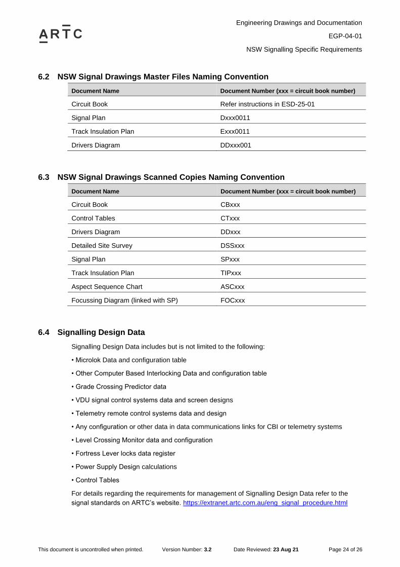
6.2 NSW Signal Drawings Master Files Naming Convention
Document Name Document Number (xxx = circuit book number)
Circuit Book Refer instructions in ESD-25-01
Signal Plan Dxxx0011
Track Insulation Plan Exxx0011
Drivers Diagram DDxxx001
6.3 NSW Signal Drawings Scanned Copies Naming Convention
Document Name Document Number (xxx = circuit book number)
Circuit Book CBxxx
Control Tables CTxxx
Drivers Diagram DDxxx
Detailed Site Survey DSSxxx
Signal Plan SPxxx
Track Insulation Plan TIPxxx
Aspect Sequence Chart ASCxxx
Focussing Diagram (linked with SP) FOCxxx
6.4 Signalling Design Data
Signalling Design Data includes but is not limited to the following:
• Microlok Data and configuration table
• Other Computer Based Interlocking Data and configuration table
• Grade Crossing Predictor data
• VDU signal control systems data and screen designs
• Telemetry remote control systems data and design
• Any configuration or other data in data communications links for CBI or telemetry systems
• Level Crossing Monitor data and configuration
• Fortress Lever locks data register
• Power Supply Design calculations
• Control Tables
For details regarding the requirements for management of Signalling Design Data refer to the
signal standards on ARTC’s website. https://extranet.artc.com.au/eng_signal_procedure.html

Engineering Drawings and Documentation
EGP-04-01
NSW Signalling Specific Requirements
This document is uncontrolled when printed. Version Number: 3.2 Date Reviewed: 23 Aug 21 Page 25 of 26
6.5 Signalling Testing Files
Microlok Interlocking Simulation System or MISS files are created during the testing period when
Microlok data is being updated and prior to installation of the updated data version.
MISS files are to be supplied to ARTC as part of the signalling As Built package provided at the
completion of the project.

Engineering Drawings and Documentation
EGP-04-01
Project Drawings Flowchart
This document is uncontrolled when printed. Version Number: 3.2 Date Reviewed: 23 Aug 21 Page 26 of 26
7 Project Drawings Flowchart