EG 202 568 - V1.1.3 - Methods for Testing and ... · • Test Descriptions (TD) ... ICMP, SIP and...
39
ETSI EG 202 568 V1.1.3 (2007-04) ETSI Guide Methods for Testing and Specification (MTS); Internet Protocol Testing (IPT); Testing: Methodology and Framework
-
Upload
truongkhuong -
Category
Documents
-
view
217 -
download
0
Transcript of EG 202 568 - V1.1.3 - Methods for Testing and ... · • Test Descriptions (TD) ... ICMP, SIP and...

ETSI EG 202 568 V1.1.3 (2007-04)
ETSI Guide
Methods for Testing and Specification (MTS);Internet Protocol Testing (IPT);
Testing: Methodology and Framework

ETSI
ETSI EG 202 568 V1.1.3 (2007-04) 2
Reference DEG/MTS-IPT-026-IP-GenTstFwk
Keywords generic, interoperability, IP, methodology, testing,
TTCN
ETSI
650 Route des Lucioles F-06921 Sophia Antipolis Cedex - FRANCE
Tel.: +33 4 92 94 42 00 Fax: +33 4 93 65 47 16
Siret N° 348 623 562 00017 - NAF 742 C
Association à but non lucratif enregistrée à la Sous-Préfecture de Grasse (06) N° 7803/88
Important notice
Individual copies of the present document can be downloaded from: http://www.etsi.org
The present document may be made available in more than one electronic version or in print. In any case of existing or perceived difference in contents between such versions, the reference version is the Portable Document Format (PDF).
In case of dispute, the reference shall be the printing on ETSI printers of the PDF version kept on a specific network drive within ETSI Secretariat.
Users of the present document should be aware that the document may be subject to revision or change of status. Information on the current status of this and other ETSI documents is available at
http://portal.etsi.org/tb/status/status.asp
If you find errors in the present document, please send your comment to one of the following services: http://portal.etsi.org/chaircor/ETSI_support.asp
Copyright Notification
No part may be reproduced except as authorized by written permission. The copyright and the foregoing restriction extend to reproduction in all media.
© European Telecommunications Standards Institute 2007.
All rights reserved.
DECTTM, PLUGTESTSTM and UMTSTM are Trade Marks of ETSI registered for the benefit of its Members. TIPHONTM and the TIPHON logo are Trade Marks currently being registered by ETSI for the benefit of its Members. 3GPPTM is a Trade Mark of ETSI registered for the benefit of its Members and of the 3GPP Organizational Partners.

ETSI
ETSI EG 202 568 V1.1.3 (2007-04) 3
Contents
Intellectual Property Rights ................................................................................................................................5
Foreword.............................................................................................................................................................5
1 Scope ........................................................................................................................................................6
2 References ................................................................................................................................................6
3 Definitions and abbreviations...................................................................................................................7 3.1 Definitions..........................................................................................................................................................7 3.2 Abbreviations .....................................................................................................................................................7
4 The IP Testing (IPT) framework ..............................................................................................................8
5 The IPT test development process............................................................................................................9 5.1 Conformance testing methodology...................................................................................................................10 5.2 Interoperability testing methodology ...............................................................................................................10
6 The Requirements Catalogue .................................................................................................................11 6.1 Entries in the Requirements Catalogue ............................................................................................................11 6.2 Naming requirements .......................................................................................................................................12
7 Developing test specifications................................................................................................................12 7.1 Conformance test specifications.......................................................................................................................12 7.1.1 Test configurations .....................................................................................................................................12 7.1.1.1 Naming conformance test configurations..............................................................................................13 7.1.1.2 Naming test components .......................................................................................................................13 7.1.2 Test Suite Structure and Test Purposes.......................................................................................................14 7.1.2.1 Test Suite Structure ...............................................................................................................................14 7.1.2.1.1 Naming test groups..........................................................................................................................14 7.1.2.2 Test Purposes ........................................................................................................................................14 7.1.2.2.1 Naming TPs.....................................................................................................................................14 7.1.2.2.2 Using the TP Language ...................................................................................................................15 7.1.3 Test Description development ....................................................................................................................16 7.1.4 Test Suite development in TTCN-3 ............................................................................................................16 7.1.4.1 Modular development of TTCN-3 ........................................................................................................16 7.1.4.2 Test Cases .............................................................................................................................................16 7.1.4.3 Synchronizing test components.............................................................................................................18 7.1.4.4 Naming TTCN-3 elements ....................................................................................................................18 7.1.4.5 Test suite parameterization....................................................................................................................19 7.2 Interoperability test specifications....................................................................................................................20 7.2.1 Test configurations .....................................................................................................................................20 7.2.1.1 Naming interoperability test configurations..........................................................................................20 7.2.1.2 Naming test components .......................................................................................................................20 7.2.2 Test Suite Structure and Test Purposes.......................................................................................................21 7.2.2.1 Test Suite Structure ...............................................................................................................................21 7.2.2.1.1 Naming test groups..........................................................................................................................21 7.2.2.2 Test Purposes ........................................................................................................................................21 7.2.2.2.1 Naming TPs.....................................................................................................................................21 7.2.2.2.2 Using the TP notation TPLan ..........................................................................................................21 7.2.3 Test Description development ....................................................................................................................22 7.2.3.1 Naming Test Descriptions.....................................................................................................................22 7.2.3.2 Presentation of TDs...............................................................................................................................22
8 TTCN-3 naming conventions.................................................................................................................23
9 TTCN-3 comment tags...........................................................................................................................24
Annex A (informative): A guide to using the Test Purpose notation, TPLan...................................25
A.1 General considerations ...........................................................................................................................25

ETSI
ETSI EG 202 568 V1.1.3 (2007-04) 4
A.1.1 Introduction ......................................................................................................................................................25 A.1.2 Structure of a TPLan specification ...................................................................................................................25 A.1.3 Choosing a suitable text editor .........................................................................................................................26
A.2 The TPLan header ..................................................................................................................................27 A.2.1 TSS Header ......................................................................................................................................................27 A.2.2 Cross-references ...............................................................................................................................................27 A.2.2.1 Requirement sources...................................................................................................................................27 A.2.2.2 Configurations ............................................................................................................................................27 A.2.3 User-defined extensions to TPLan ...................................................................................................................28 A.2.3.1 General layout of user definitions...............................................................................................................28 A.2.3.2 Header fields...............................................................................................................................................29 A.2.3.3 Entities ........................................................................................................................................................29 A.2.3.4 Events .........................................................................................................................................................30 A.2.3.5 Conditions...................................................................................................................................................30 A.2.3.6 Values .........................................................................................................................................................31 A.2.3.7 Units............................................................................................................................................................31 A.2.3.8 Keywords....................................................................................................................................................31 A.2.3.9 Syntactical context ......................................................................................................................................32
A.3 Test Purposes..........................................................................................................................................32 A.3.1 Grouping TPs ...................................................................................................................................................32 A.3.1.1 TP header ....................................................................................................................................................33 A.3.1.2 TP body.......................................................................................................................................................34 A.3.1.2.1 Preconditions.........................................................................................................................................34 A.3.1.2.2 Stimulus and response...........................................................................................................................34 A.3.1.2.2.1 The when and then construct .......................................................................................................34 A.3.1.2.2.2 Identifying the contents of message events .....................................................................................35 A.3.1.2.2.3 Interactions with the user.................................................................................................................36 A.3.1.2.2.4 Establishing the order of a sequence of events ................................................................................36 A.3.1.2.2.5 The "do nothing" response ..............................................................................................................37
Annex B (informative): Bibliography:..................................................................................................38
History ..............................................................................................................................................................39

ETSI
ETSI EG 202 568 V1.1.3 (2007-04) 5
Intellectual Property Rights IPRs essential or potentially essential to the present document may have been declared to ETSI. The information pertaining to these essential IPRs, if any, is publicly available for ETSI members and non-members, and can be found in ETSI SR 000 314: "Intellectual Property Rights (IPRs); Essential, or potentially Essential, IPRs notified to ETSI in respect of ETSI standards", which is available from the ETSI Secretariat. Latest updates are available on the ETSI Web server (http://webapp.etsi.org/IPR/home.asp).
Pursuant to the ETSI IPR Policy, no investigation, including IPR searches, has been carried out by ETSI. No guarantee can be given as to the existence of other IPRs not referenced in ETSI SR 000 314 (or the updates on the ETSI Web server) which are, or may be, or may become, essential to the present document.
Foreword This ETSI Guide (EG) has been produced by ETSI Technical Committee Methods for Testing and Specification (MTS).

ETSI
ETSI EG 202 568 V1.1.3 (2007-04) 6
1 Scope The present document gives guidelines on the use of a common method for developing test specifications for standardized IP-related communications systems and protocols. This method is applicable to all such systems and protocols.
The underlying method is based on the methodologies specified in ISO/IEC 9646-1 [5] for conformance tests and EG 202 237-1 [1] for interoperability tests. It provides guidance on the development and use of the following key elements of the method:
• a Requirements Catalogue (RC);
• a Test Suite Structure (TSS) and Test Purposes (TP);
• Test Descriptions (TD) - interoperability;
• a TTCN-3 library of data types and values, templates and functions;
• an Abstract Test Suite (ATS) - conformance.
The methodology also offers general guidance on naming conventions and other style-related issues.
Although the present document has been developed primarily for use in the testing of internet-related protocols, it could equally be used in other areas of protocol test specification.
2 References The following documents contain provisions which, through reference in this text, constitute provisions of the present document.
• References are either specific (identified by date of publication and/or edition number or version number) or non-specific.
• For a specific reference, subsequent revisions do not apply.
• For a non-specific reference, the latest version applies.
Referenced documents which are not found to be publicly available in the expected location might be found at http://docbox.etsi.org/Reference.
NOTE: While any hyperlinks included in this clause were valid at the time of publication ETSI cannot guarantee their long term validity.
[1] ETSI EG 202 237: "Methods for Testing and Specification (MTS); Internet Protocol Testing (IPT); Generic approach to interoperability testing".
[2] ETSI EG 201 770 (V4.2.2): "Methods for Testing and Specification (MTS); Test Synchronization Protocol 1 plus (TSP1+) specification".
[3] ETSI EG 202 106 (V2.1.1): "Methods for Testing and Specification (MTS); Guidelines for the use of formal SDL as a descriptive tool".
[4] ETSI TS 102 351 (2005): "Methods for Testing and Specification (MTS); Internet Protocol Testing (IPT); IPv6 Testing: Methodology and Framework".
[5] ISO/IEC 9646-1 (1992): "Information Technology - Open Systems Interconnection - Conformance Testing Methodology and Framework - Part 1: General concepts".

ETSI
ETSI EG 202 568 V1.1.3 (2007-04) 7
3 Definitions and abbreviations
3.1 Definitions For the purposes of the present document, the following terms and definitions apply:
behavioural function: TTCN-3 function which specifies actions which result in the sending of messages to one or more observed interface
computational function: TTCN-3 function which specifies actions which modifies data values but does not result in the sending of messages to one or more observed interface
Equipment Under Test (EUT): grouping of one or more devices which has not been previously shown to interoperate with previously Qualified Equipment (QE) [1]
internet protocols: any protocol, including IPv4 and IPv6, designed specifically for use in an internet environment. Such protocols include DHCP, ICMP, SIP and IKEv2
Qualified Equipment (QE): grouping of one or more devices that has been shown, by rigorous and well-defined testing, to interoperate with other equipment [1]
NOTE: Once an EUT has been successfully tested against a QE, it may be considered to be a QE, itself.
TPLan: notation for expressing test purposes
3.2 Abbreviations For the purposes of the present document, the following abbreviations apply:
3GPP 3rd Generation mobile Partnership Project ATS Abstract Test Suite EUT Equipment Under Test IETF Internet Engineering Task Force IFS Interoperable Functions Statement IP Internet Protocol IPv4 Internet Protocol version 4 IPv6 Internet Protocol version 6 IPT IP Testing IUT Implementation Under Test MTC Main Test Component NGN Next Generation Network PICS Protocol Implementation Conformance Statement PIXIT Protocol Implementation eXtra Information for Testing PTC Parallel Test Component QE Qualified Equipment RC Requirements Catalogue RFC Request For Comments (IETF terminology for a draft standard) RQ Requirement SUT System Under Test TC Test Case TD Test Description TP Test Purpose TSP1+ Test Synchronization Protocol 1+ TSS Test Suite Structure TTCN-3 Testing and Test Control Notation edition 3 UDP User Datagram Protocol UT Upper Tester

ETSI
ETSI EG 202 568 V1.1.3 (2007-04) 8
4 The IP Testing (IPT) framework ETSI test specifications are usually developed for a single base protocol standard or for a coherent set of standards. As such, it is possible to follow the methodology specified for conformance test development in ISO/IEC 9646-1 [5] without much difficulty. However, Internet Protocol (IP) testing requirements are, in many cases, distributed across a wide range of documents and, thus, an adaptation of the ISO/IEC 9646 approach to test development is necessary. Also, for readability, consistency and to ease reusability of TTCN-3 code it is necessary to apply some guidelines on the use of TTCN-3.
It is this approach that is referred to as the "IP Testing (IPT) Framework".
As its name implies, the framework is oriented towards the production of Test specifications for internet protocols. The IPT Framework comprises:
• a documentation structure:
- catalogue of requirements;
- Test Suite Structure (TSS);
- Test Purposes (TP):
� conformance;
� interoperability.
• a methodology linking the individual elements of a test specification together:
- style guidelines and examples;
- naming conventions;
- a structured notation for TPs;
- guidelines on the development of TTCN-3 Test Cases (TCs);
- guidelines on the use of tabulated English Test Descriptions (TDs).

ETSI
ETSI EG 202 568 V1.1.3 (2007-04) 9
5 The IPT test development process The process to be followed when developing IP test specifications is shown in figure 1.
Figure 1: IPT test development process

ETSI
ETSI EG 202 568 V1.1.3 (2007-04) 10
The process begins with the analysis of the primary public standards related to the IP communications system to be tested (most often IETF RFCs) and a range of secondary inputs which include:
• current industry practice;
• existing test documentation from any relevant fora and other established sources;
• specifications related to the use of communications system in other standardization bodies.
The result of this analysis is the identification and classification of a full range of requirements which is recorded in the Requirements Catalogue and used as the basis for both conformance and interoperability test specifications.
5.1 Conformance testing methodology Conformance test specifications should be produced following the methodology described in ISO/IEC 9646-1 [5]. In summary, this methodology begins with the collation and categorization of the requirements to be tested into a tabular form which is normally referred to as the "Protocol Implementation Conformance Statement" (PICS). Each PICS relates to a specific protocol standard. In those cases where the requirements are distributed across a large number of documents there may be very little benefit in producing an individual PICS for each document. Consequently, the requirements should be collected together and categorized in a single document, referred to in figure 1 as the Requirements Catalogue. This document could be structured as an overall PICS covering the requirements of all the relevant specifications.
For each requirement in the catalogue, one or more tests should be identified and classified into a number of groups which will provide a structure to the overall test suite (TSS). A brief Test Purpose (TP) should then be written for each identified test and this should make it clear what is to be tested but not how this should be done. Although not described or mandated in ISO 9646-1, in many situations (particularly where the TPs are complex) it may be desirable to develop a Test Description (TD) for each TP. The TD describes in plain language (often tabulated) the actions required to reach a verdict on whether an implementation passes or fails the test. Finally, a detailed Test Case (TC) is written for each TP. In the interests of test automation, TCs are usually combined into an Abstract Test Suite (ATS) using a specific testing language such as TTCN-3.
5.2 Interoperability testing methodology For a certification (or branding or logo) scheme to be meaningful, it is necessary that interoperability testing is carried out in addition to conformance testing and that this is done in accordance with a comprehensive and structured suite of tests. In the context of the present document, it is this type of testing which is referred to as "Interoperability Testing". The purpose of interoperability testing is to prove that the end-to-end functionality between (at least) two communicating systems is as required by the standard(s) on which those systems are based. A methodology for developing such interoperability test specification is described in EG 202 237 [6] and this should be used as a guide when developing test suites. This methodology is based extensively on ISO/IEC 9646-1 [5] but with some modifications to make it suitable for interoperability testing.
In EG 202 237 [7], the Interoperable Functions Statement (IFS) replaces the PICS and is a statement of which functions supported by the protocol have been implemented. However, in this framework these functions may be clearly incorporated in the Requirements Catalogue.
As with conformance testing, the interoperability test specification process begins with the identification and classification of requirements for which tests should be developed. Again, the grouping of requirements into the TSS is not governed by any strict rules but should be relevant to the project overall. TPs should be written for each selected requirement and one or more TDs specified for each TP. Unlike the conformance process, the specification of TDs should not be considered as optional. However, it is only in cases where suitable user interfaces are available that it is possible to develop Test Cases in a language such as TTCN-3.
ETSI
ETSI EG 202 568 V1.1.3 (2007-04) 11
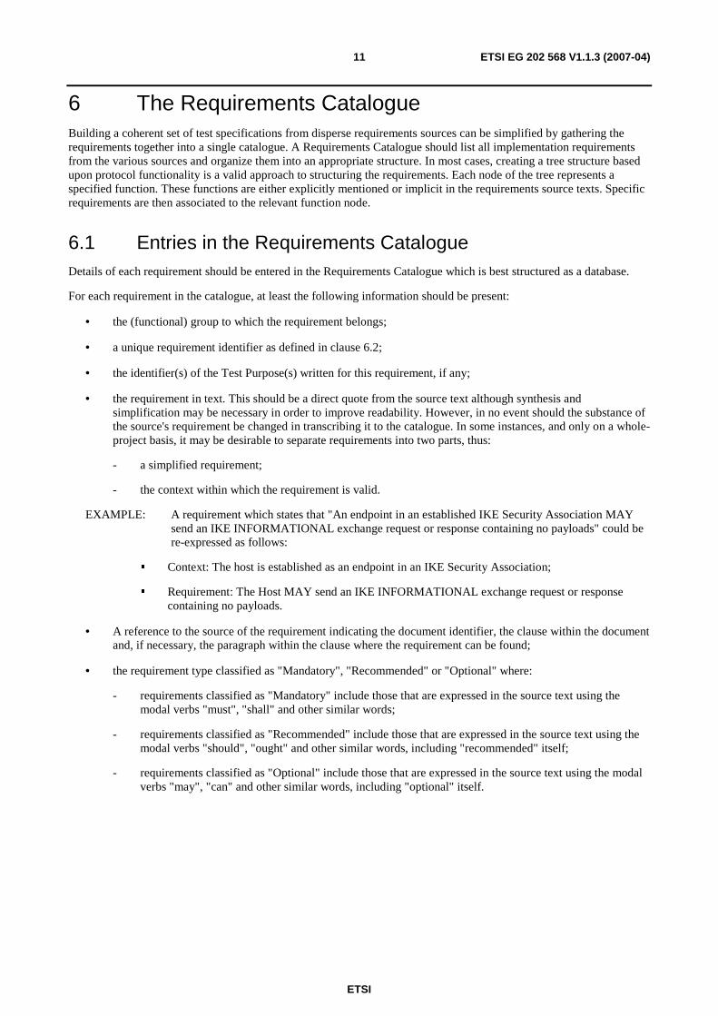
6 The Requirements Catalogue Building a coherent set of test specifications from disperse requirements sources can be simplified by gathering the requirements together into a single catalogue. A Requirements Catalogue should list all implementation requirements from the various sources and organize them into an appropriate structure. In most cases, creating a tree structure based upon protocol functionality is a valid approach to structuring the requirements. Each node of the tree represents a specified function. These functions are either explicitly mentioned or implicit in the requirements source texts. Specific requirements are then associated to the relevant function node.
6.1 Entries in the Requirements Catalogue Details of each requirement should be entered in the Requirements Catalogue which is best structured as a database.
For each requirement in the catalogue, at least the following information should be present:
• the (functional) group to which the requirement belongs;
• a unique requirement identifier as defined in clause 6.2;
• the identifier(s) of the Test Purpose(s) written for this requirement, if any;
• the requirement in text. This should be a direct quote from the source text although synthesis and simplification may be necessary in order to improve readability. However, in no event should the substance of the source's requirement be changed in transcribing it to the catalogue. In some instances, and only on a whole-project basis, it may be desirable to separate requirements into two parts, thus:
- a simplified requirement;
- the context within which the requirement is valid.
EXAMPLE: A requirement which states that "An endpoint in an established IKE Security Association MAY send an IKE INFORMATIONAL exchange request or response containing no payloads" could be re-expressed as follows:
� Context: The host is established as an endpoint in an IKE Security Association;
� Requirement: The Host MAY send an IKE INFORMATIONAL exchange request or response containing no payloads.
• A reference to the source of the requirement indicating the document identifier, the clause within the document and, if necessary, the paragraph within the clause where the requirement can be found;
• the requirement type classified as "Mandatory", "Recommended" or "Optional" where:
- requirements classified as "Mandatory" include those that are expressed in the source text using the modal verbs "must", "shall" and other similar words;
- requirements classified as "Recommended" include those that are expressed in the source text using the modal verbs "should", "ought" and other similar words, including "recommended" itself;
- requirements classified as "Optional" include those that are expressed in the source text using the modal verbs "may", "can" and other similar words, including "optional" itself.

ETSI
ETSI EG 202 568 V1.1.3 (2007-04) 12
6.2 Naming requirements A unique name should be provided for each requirement in the catalogue. There is no firm rule on how this identifier should be constructed but the following method has been used successfully and can be adapted for most applications. Each requirement is given a unique name which has the following structure:
RQ_nnn_mmmm
3-digit field identifying the logical grouping to which the requirement belongs
4-digit identifier
The 3-digit field, "nnn", is used to group requirements in a logical way which is relevant to the project. This grouping could be based upon overall functionality (for example, 001 = Security, 002 = Mobility), the source specification (for example, 004 = EN 345 678, 005 = ES 234 567) or any other factor which has meaning within the particular project.
7 Developing test specifications
7.1 Conformance test specifications
7.1.1 Test configurations
The development of specific conformance test configurations is unlikely to be helpful at an early stage of the process as there are often numerous possibilities for realizing a particular set of Test Purposes. However, in those instances where there are only limited options for testing or where a specific configuration is required, it can be very useful to define valid abstract architectures (configurations) for testing. Such configurations should identify the roles required for the test components and the communications paths between those components.
Figure 2 shows an example configuration which could be used for conformance testing an IPv6 router. It identifies the IUT, the Main Test Component (MTC) and the Parallel Test Components (PTCs) with the roles that each plays.

ETSI
ETSI EG 202 568 V1.1.3 (2007-04) 13
Figure 2: Example conformance testing configuration
7.1.1.1 Naming conformance test configurations
Test configurations should be named so that they can be uniquely referenced in, for example, the TTCN-3 code or TP Language headers (clause 7.1.2.2.2).
As an example of configuration naming that has been successfully used in practice (see figure 2), names could be of the form "CF_" followed by between three and eight characters (providing a simple descriptive tag) and a two digit unique sequence number. This identifier should be included in any diagram associated with the configuration, as shown in figure 2.
7.1.1.2 Naming test components
The components in each test configuration should be systematically and unambiguously identified. This naming should be based on the role of each component, for example:
• HS Host;
• RT Router;
• MD Mobile Node;
• HA Home Agent.
In addition, the abbreviations UT and LT can be used for the Upper Tester and the Lower Tester.
Each role should be followed by a two-digit sequence number that uniquely identifies that component. This is necessary when more than one component plays the same role. The role and the sequence number should be separated by an underscore.
EXAMPLE: HS_01, HS_02, RT_01, RT_02.

ETSI
ETSI EG 202 568 V1.1.3 (2007-04) 14
7.1.2 Test Suite Structure and Test Purposes
7.1.2.1 Test Suite Structure
Test Suite Structure (TSS) groups should be chosen according to natural divisions in the base specification(s) and should be meaningful within the context of the testing project. The following list identifies a number of examples of valid TSS grouping criteria:
• The architecture of the testing configuration, for example all test purposes explicitly requiring an Upper Tester are collected into a single group.
• IUT behaviour, for example test purposes related to "Normal" behaviour are separated from those related to "Exceptional" behaviour.
• Base protocol specification table of contents, for example test purposes related to each described function within the base specification are grouped together according to those functions.
In most cases it is useful to base TSS grouping on a combination of criteria in order to avoid a structure that is "flat" and, therefore, not particularly meaningful.
7.1.2.1.1 Naming test groups
TP groups should have a short name (or identifier) and a longer, more readable title. The short name should be derived from the longer title (i.e. it should be a two or three letter abbreviation of the longer title). For example, if the long title is "Router", the short name should be: "RT". It is recommended that the title is followed by the short name in parentheses, for example: "Router (RT)". In the case of subgroups, both the title and the short name should reflect the sub structuring, essentially making them path names.
The group delimiter within the title should be "/" and the delimiter within the short name should be: "_". As a further example, the group "Provide IPv6 Services (P6S)" which is a sub group of the "Router (RT)" group, has the title:
Router(RT)/Provide IPv6 Services(P6S).
and the short name:
RT_P6S.
7.1.2.2 Test Purposes
A Test Purpose (TP) should be written for each potential test of each identified requirement remembering that:
• a requirement may need more than one TP to ensure that it is fully tested;
• some requirements may not be testable and so will have no TPs; and
• it may be possible to test more than one requirement with a single TP.
As well as describing what is to be tested, the TP should identify the initial conditions to be established before testing can take place, the required status of the Implementation Under Test (IUT) from which testing can proceed and the criteria upon which verdicts can be assigned.
The contents of a TP should be limited to a description of what is to be tested rather than how that testing is to be carried out.
7.1.2.2.1 Naming TPs
Each TP should be given an identifier which is unique within the overall project. There is no fixed requirement for the format of a TP identifier but each project should implement a common naming convention for all TPs.

ETSI
ETSI EG 202 568 V1.1.3 (2007-04) 15
An example of a TP naming scheme that has been proved to work in practice constructs TP identifiers as follows:
• each Test Purposes identifier is introduced by the prefix "TP_";
• a 3 to 8 character string which can be used to sub-divide TPs into major groupings within a project if necessary;
• a four-digit sequence number which is unique for each requirement (or group of requirements if a single TP is able to test more than one requirement); and
• a two digit sequence number to permit multiple TPs to be derived from a single requirement or group of requirements.
The following examples show how this convention can be applied:
• TP_COR_0147_01;
• TP_Security_0109_17;
• TP_DHCP_0033_05;
• TP_Router_0006_32.
7.1.2.2.2 Using the TP Language
There is considerable benefit to be gained by having all Test Purposes written in a similar and consistent way. With this in mind, a simple, structured notation has been developed for the expression of TPs. This notation is described fully in ES 202 553 (see bibliography) and is referred to as "TPLan".
The benefits of using TPLan are:
• consistency in test purpose descriptions - less room for misinterpretation;
• simpler segregation of preconditions and test body;
• automatic test purpose syntax checking;
• a basis for a TP transfer format;
• possible TTCN-3 code stub generation;
• possibility to graphically or textually render TP descriptions for different users.
An example of the use of TPLan to express a conformance TP is shown below:
TP id : TP_Security_1573_01 summary : 'Test reaction on multicast IPv6 packets for unknown multicast group SA' RQ ref : RQ_002_2009, RQ_002_2008 Role : Ipsec_host Config : CF_SEC_01 TC ref : TC_SEC_1573_01 with { IUT established 'in a multicast group AH Security Association' } ensure that { when { IUT receives a multicast IPv6Packet containing an Authentication_Header containing a Security_Parameter_Index indicating 'a value unrelated to the established multicast group SA' } then { IUT discards the IPv6Packet } }
Guidelines on the use of TPLan can be found in ES 202 553 (see bibliography).

ETSI
ETSI EG 202 568 V1.1.3 (2007-04) 16
7.1.3 Test Description development
In some instances, particularly where there is a considerable difference in complexity between the TPs and the TCs, it is worthwhile adding an extra design stage between these two. This involves the development of a Test Description (TD) for each test. A TD typically specifies the sequence of actions required to realize the verdict identified in the TP. There is no recommended method for developing and writing TDs. However, the method recommended for interoperability test specifications (see clause 7.2.3) could easily be applied here.
7.1.4 Test Suite development in TTCN-3
7.1.4.1 Modular development of TTCN-3
In order to optimize the reuse of TTCN-3 code, test cases should be developed using a modular approach. Individual modules should be easily accessible as well structured libraries of functions.
As an example, elements within a Test Suite could be developed, stored and maintained together using the following categories:
• Test Cases.
• Test Case functions.
• Test Purpose functions.
• Preambles.
• Postambles.
Although these functions could specify testing behaviour directly in TTCN-3, most should do little more than invoke reusable functions and use data and templates from both internal (project-specific) and external (general purpose) libraries.
7.1.4.2 Test Cases
When developing the TTCN-3 specification, one of two basic testing configurations should be considered in each test case implementation. The simpler of these is the non-concurrent arrangement, shown in figure 3, where there is only one TTCN-3 test component, the Main Test Component (MTC), which executes all aspects of the tests.
Figure 3: Non-concurrent TTCN-3 testing configuration

ETSI
ETSI EG 202 568 V1.1.3 (2007-04) 17
The more complex, and more usual, test arrangement distributes a test case implementation over two or more parallel components. This concurrent configuration is shown in figure 4.
Tester
PTCnPTC1
Test Case Function
Preamble
TP Function
Postamble
SUT Test Case Function
MTC
Test Case
Create/Start PTCs
Synchronize PTC Preambles
Synchronize PTC TPs
Finalize Test & Stop
IUTSynchronization
Synchronization
Preamble
TP Function
Postamble
Synchronization
Synchronization
Figure 4: Concurrent TTCN-3 testing configuration
In this configuration the MTC initiates the test by invoking a test case function on each Parallel Test Component (PTC) and coordinates the execution of the PTCs using synchronization. Each PTC executes all aspects of a test related to its own particular role. Consequently, the MTC does not interact with the SUT.
The types of elements identified in Figures 3 and 4 should be used as follows:
• a test case in a non-concurrent configuration (figure 3):
- invokes a preamble function;
- invokes a test purpose function; and
- invokes a postamble function.
• a test case in a concurrent configuration (figure 4):
- invokes the test case functions in each of the PTCs; and
- synchronizes the test case functions prior to execution.
• a test case function in a concurrent configuration (figure 4):
- invokes a preamble function;
- invokes a test purpose function; and
- invokes a postamble function.

ETSI
ETSI EG 202 568 V1.1.3 (2007-04) 18
• a preamble function:
- performs the actions required to place the IUT into the condition required by the test purpose function;
- if required, sets the PTC's verdict based on the success of these actions; and
- synchronizes with the MTC.
• a test purpose function:
- performs the actions required the test component, in its assigned role, to achieve the test as specified in the Test Purpose;
- sets the PTC's verdict based on the success of these actions; and
- synchronizes with the MTC.
• a postamble function:
- performs the actions required to return the IUT to a known quiescent state after completing the test;
- if required, sets the PTC's verdict based on the success of these actions.
7.1.4.3 Synchronizing test components
The synchronization of distributed TTCN-3 elements is an essential part of the development of a test suite. Consequently, a suitable and well-defined synchronization protocol should be used, even if this entails designing and developing one specifically for the test application. An example of such an approach can be found in the IPv6 Testing Framework, TS 102 351 [4]. The Test Synchronization Protocol (TSP1+) [2] is an example of a protocol which has been specified explicitly for the control and synchronization of distributed test systems.
7.1.4.4 Naming TTCN-3 elements
As with TP naming, there is no fixed requirement for the format of TTCN-3 identifiers but each project should implement a common naming convention for all elements. The following examples of naming guidelines are based on the modularization of TTCN-3 described in clause 7.1.4.1 and are derived from practical experience:
• Test cases:
- As there is usually a one-to-one relationship between TPs and TCs, they should share a common numbering scheme with a prefix (or other device) to distinguish between them. Following on from the TP naming example described in clause 7.1.2.2.1, Test Cases should be given the prefix, "TC", thus:
� TC_COR_0147_01;
� TC_Security_0109_17;
� TC_DHCP_0033_05;
� TC_Router_0006_32.
• Test case functions:
- As there is a one-to-one relationship between TCs and TC functions, they should share a common numbering scheme but with the TC function identifier prefixed with "f_";
- The identifier of a TC Function should include a suffix which indicates the role of the associated test component as well as the test case identifier. The role indicator should be a two or three character abbreviation of the role, as shown in the following example (where the "RT" suffix indicates that the PTC is to assume the role of a Router):
� f_TC_COR_0147_01_RT

ETSI
ETSI EG 202 568 V1.1.3 (2007-04) 19
- In those cases where more than one instance of a particular role is defined by a particular configuration, a 2-digit sequence number may be appended to the role as shown in the following examples:
� f_TC_COR_0147_01_RT_02
� f_TC_COR_0147_01_RT_01
• TP functions:
- TP function identifiers should begin with the prefix "f_TP_" but should followed by a descriptive name rather than the remainder of the TP identifier itself. This is because the TP function is likely to be reusable in other TCs where an identifier tied to a specific TP may cause confusion. The following are examples of TP function identifiers:
� f_TP_receiveEchoReplyAndTestChecksum.
� f_TP_sendHopLimitZeroAndReceiveTimeExceeded.
� f_TP_echoProcedure.
- If it is necessary to associate a TP function with a particular component in a test configuration, TP function name should be suffixed with an indicator of the role of the TP function in the test configuration. For example:
� f_TP_receiveEchoReplyAndSendRedirect_RT.
- In those cases where more than one instance of a particular role is defined by a particular configuration, a 2-digit sequence number may be appended to the role as shown in the following example:
� f_TP_receiveEchoReplyAndSendRedirect_RT_01.
• Preambles and Postambles:
• Preamble and postamble functions should start with the prefix "f_" followed by "PR" for preambles and "PO" for postambles. These prefixes are followed by a text string specifying the role of the preamble or postamble. For example:
- f_PR_BasicInitialise.
- f_PO_BasicShutdown.
7.1.4.5 Test suite parameterization
It is often necessary to parameterize a test suite so that values not known at the time of writing the test cases can be used in testing. These values (input to the TTCN-3 ATS as module parameters) may depend on the IUT or the test system on which the test suite is being run.
NOTE: Test suite parameter values correspond to values normally found in a PICS or PIXIT.
Table 1 shows an example of how test suite parameters could be documented. The IUT Value column, highlighted in grey, is completed at the time of testing.
Table 1: Module (test suite) parameters
Organization: IPv6 Label Parameter Name Description Reference Type IUT Value
R_HOST IP address for remote host N/A IPAddress T1 Response timer RFC XYZ, 3.2 integer

ETSI
ETSI EG 202 568 V1.1.3 (2007-04) 20
7.2 Interoperability test specifications
7.2.1 Test configurations
For each test or group of tests specified in an interoperability test suites, a configuration should be defined to identify the role of each of the test components and the communications paths between those components.
It is important to note that, at this stage, a test configuration should be no more than an abstract architecture and should not attempt to define physical networks and entities.
Figure 5 shows an example configuration for interoperability testing.
QE2
Host
HS_01
EUT
Router
RT_01
QE3
Host
HS_02
QE4
End Node
EN_02
Configuration
CF_IPv6Core_15
QE1
End Node
EN_01
Figure 5: Example interoperability testing configuration
7.2.1.1 Naming interoperability test configurations
Interoperability test configurations should be named so that they can be uniquely referenced in, for example, an interoperability test description or in the TP Language headers (clause 7.1.2.2.2).
As an example of configuration naming that has been successfully used in practice (see figure 5), names could be of the form "CF_" followed by between three and eight characters (providing a simple descriptive tag) and a two digit unique sequence number. This identifier should be included in any diagram associated with the configuration, as shown in figure 5.
7.2.1.2 Naming test components
The components in each test configuration should be systematically and unambiguously identified. This naming is based on the role of each component, for example:
• HS Host;
• RT Router;
• CD Correspondent Node;
• SG Security Gateway.
Each role should be followed by a two-digit sequence number that uniquely identifies that component. This is necessary when more than one component plays the same role. The role and the sequence number should be separated by an underscore. For example:
• HS_01, HS_02, RT_01, RT_02.

ETSI
ETSI EG 202 568 V1.1.3 (2007-04) 21
7.2.2 Test Suite Structure and Test Purposes
7.2.2.1 Test Suite Structure
Test Suite Structure (TSS) groups should be chosen according to natural divisions in the base specification(s) and should meaningful within the context of the testing project. The following list identifies a number of examples of valid TSS grouping criteria:
• The functionality supported by the base protocol, for example the test purposes associated with each supported function are grouped together according to those functions.
• EUT behaviour, for example the test purposes related to "Normal" behaviour are segregated from those related to "Exceptional" behaviour.
• EUT role, for example where the base specification expects the EUT to be able to play multiple roles (e.g. router and host), test purposes are grouped according to those roles.
In most cases it is useful to base TSS grouping on a combination of criteria in order to avoid a structure that is "flat" and, therefore, not particularly meaningful.
7.2.2.1.1 Naming test groups
There is no requirement for groups within an interoperability TSS to be given a structured name (see clause 7.1.2.1.1). Each group should be given a meaningful name which adequately describes what the group represents. The following examples illustrate this approach:
• IKEv2 - Message length.
• IPv6 Core - Process Extension Headers.
7.2.2.2 Test Purposes
A Test Purpose (TP) should be written for each potential test of each identified requirement remembering that:
• a requirement may need more than one TP to ensure that it is fully tested;
• some requirements may not be testable or relevant to interoperability and so will have no TPs; and
• it may be possible to test more than one requirement with a single TP.
As well as describing what is to be tested, the TP should identify the initial conditions to be established before testing can take place, the required status of the Equipment Under Test (EUT) from which testing can proceed and the criteria upon which verdicts can be assigned.
The contents of a TP should be limited to a description of what is to be tested rather than how that testing is to be carried out.
7.2.2.2.1 Naming TPs
Each TP should be given an identifier which is unique within the overall project. There is no fixed requirement for the format of a TP identifier but each project should implement a common naming convention for all TPs.
An example of a TP naming scheme that has been proved to work in practice is described in clause 7.1.2.2.1.
7.2.2.2.2 Using the TP notation TPLan
There is considerable benefit to be gained by having all Test Purposes written in a similar and consistent way. With this in mind, a simple, structured notation has been developed for the expression of TPs. This notation is described fully in ES 202 553 (see bibliography) and is referred to as "TPLan".
The benefits of using TPLan are identified in clause 7.1.2.2.2.

ETSI
ETSI EG 202 568 V1.1.3 (2007-04) 22
An example of the use of TPLan to express an interoperability TP is shown below:
TP id : TP_MOB_1457_01 summary : 'Correspondent Node creates a new entry in its binding cache when receiving a valid Binding Update' RQ ref : RQ_001_2039 Role : Correspondent_Node config : CF_MOB_04 TD ref : TD_MOB_1457_01 with { QE4 away_from_home and QE4 registered to QE1 and QE4 configured 'to perform route optimization' and EUT configured 'to perform route optimization' } ensure that { when { EUT receives a packet from QE4 indicating that a response is required } then { EUT sends response directly to QE4 } }
Guidelines on the use of TPLan can be found in ES 202 553 (see bibliography).
7.2.3 Test Description development
Test Descriptions (TDs) specify the detailed steps that must be followed in order to achieve the stated purpose of each interoperability test. These steps should be specified in a clear and unambiguous way but without placing unreasonable restrictions on how the step is performed. TDs written in a structured and tabulated natural language are ideal when the tests themselves are to be performed manually. If, however, tests are to be automated, test cases should be written in TTCN-3. The development of TTCN-3 test cases does not mean that TDs should not also be produced because they have significant value as higher-level designs of the test cases.
NOTE: Although TDs are primarily intended for use in the specification of interoperability tests, they may also prove to be a useful intermediate design aid for conformance tests.
7.2.3.1 Naming Test Descriptions
As with TCs, there is a one-to-one relationship between TPs and TDs. Consequently, the naming of TDs is similar to that described for TCs in clause 7.1.4.4 except that the prefix "TD_" is used instead of "TC_", thus:
• TD_COR_0147_01;
• TD_Security_0109_17;
• TD_DHCP_0033_05;
• TD_Router_0006_32.
7.2.3.2 Presentation of TDs
Test Descriptions should be presented as a sequence of activities and verdicts that can be followed manually by an operator, as described in EG 202 237 [8]. This sequence should be tabulated with header information and the associated Test Purpose as shown in table 2.

ETSI
ETSI EG 202 568 V1.1.3 (2007-04) 23
Table 2: Example Test Description
Test Description Identifier: TD_COR_1064_01 Test Purpose: TP_COR_1064_01 Summary: An IPv6 node fragments a packet larger than the available PMTU before sending it Roles: Host, Router Configuration: CF_COR_23 References: RQ_001_2136, RQ_001_2137, RQ_001_2251 with { the MTU on Link1 set greater than the MTU on Link2 } ensure that { when { EUT is requested to send a packet of greater length than the MTU of Link2 to QE2 } then { QE2 indicates receipt of the packet unmodified }
} Pre-test conditions:
• MTU on the link between QE1 and the EUT set to a value greater than that on the link between QE1 and QE2
Step Test Sequence Verdict Pass Fail
1 Cause EUT to send an Echo Request to QE2 with a packet size greater than the MTU between QE1 and QE2 but less than the PMTU between QE1 and EUT and with each octet set to the hexadecimal value "F0"
2 Check: Does protocol monitor show that the Echo Request was sent from EUT to QE2?
Yes No
3 Check: Does EUT receive a Packet Too Big message from QE1 Yes No 4 Cause EUT to send an Echo Request to QE2 with a packet size greater
than the MTU between QE1 and QE2 but less than the PMTU between QE1 and EUT and with each octet set to the hexadecimal value "F0"
5 Check: Does protocol monitor show that the Echo Request was sent from EUT to QE2?
Yes No
6 Check: Does QE1 receive an Echo Reply from QE2 with the packet length the same as the Echo Request and with each octet containing the hexadecimal value "F0"?
Yes No
Observations
8 TTCN-3 naming conventions For the sake of consistency within a testing project, a common naming convention should be defined for all TTCN-3 elements which require an identifier.
The following scheme is an example of a naming convention which has been used successfully across a wide range of projects:
• when constructing meaningful identifiers, the general guidelines specified for naming in clause 6 of EG 202 106 [3] should be followed;
• in most cases, identifiers should be prefixed with a short alphabetic string (specified in table 3) indicating the type of TTCN-3 element it represents;
• prefixes should be separated from the body of the identifier with an underscore ("_"):
EXAMPLE 1: c_sixteen.
• only module names, data type names and module parameters should begin with an upper-case letter. All other names (i.e. the part of the identifier following the prefix) should begin with a lower-case letter;
• the start of second and subsequent words in an identifier should be indicated by capitalizing the first character. Underscores should not be used for this purpose:
EXAMPLE 2: f_authenticateUser().
Table 3 specifies the naming guidelines for each element of the TTCN-3 language indicating the recommended prefix and capitalization.

ETSI
ETSI EG 202 568 V1.1.3 (2007-04) 24
Table 3: IPT TTCN-3 naming convention
Language element Naming convention Prefix Example Notes Module Use upper-case initial letter none IPv6Templates TSS grouping Use all upper-case letters as
specified in clause 7.1.2.1.1 none TP_RT_PS_TR
Item group within a module
Use lower-case initial letter none messageGroup
Data type Use upper-case initial letter none SetupContents Message template Use lower-case initial letter m_ m_setupInit
m_setupBasic Note 1
Message template with wildcard or matching expression
Use lower-case initial letters mw_ mw_anyUserReply
Note 2
Signature template Use lower-case initial letter s_ s_callSignature Port instance Use lower-case initial letter none signallingPort Test component ref Use lower-case initial letter none userTerminal Constant Use lower-case initial letter c_ c_maxRetransmission External constant Use lower-case initial letter cx_ cx_macId Function Use lower-case initial letter f_ f_authentication() External function Use lower-case initial letter fx_ fx_calculateLength() Altstep (incl. Default) Use lower-case initial letter a_ a_receiveSetup() Test case Use numbering as specified in
clause 7.1.3.2.1 TC_ TC_COR_0009_47_ND
Variable (local) Use lower-case initial letter v_ v_macId Variable (defined within a component)
Use lower-case initial letters vc_ vc_systemName
Timer (local) Use lower-case initial letter t_ t_wait Timer (defined within a component)
Use lower-case initial letters tc_ tc_authMin
Module parameter Use all upper case letters none PX_MAC_ID Note 3 Parameterization Use lower-case initial letter p_ p_macId Enumerated Value Use lower-case initial letter e_ e_syncOk NOTE 1: This prefix must be used for all template definitions which do not assign or refer to templates with
wildcards or matching expressions, e.g. templates specifying a constant value, parameterized templates without matching expressions, etc.
NOTE 2: This prefix must be used in identifiers for templates which either assign a wildcard or matching expression ( e.g. ?, *, value list, ifpresent, pattern, etc) or reference another template which assigns a wildcard or matching expression.
NOTE 3: In this case it is acceptable to use underscore as a word delimiter.
9 TTCN-3 comment tags Any TTCN-3 definition submitted to the Open Testing Library should contain embedded comment tags. These comment tags can be used by automatic tools to extract information from the TTCN-3 code to create, for example, HTML-based reference documentation. ES 201 873-10 (see bibliography) specifies a complete set of TTCN-3 documentation tags and it is these that should be used. These tags and their usage are summarized in table 4.
Table 4: TTCN-3 Comment Tags
Tag Description @author Specifies the names of the authors or an authoring organization which either has created or
is maintaining a particular piece of TTCN-3 code. @desc Describes the purpose of a particular piece of TTCN-3 code. The description should be
concise yet informative and describe the function and use of the construct. @remark Adds extra information, such as the highlighting of a particular feature or aspect not covered
in the description. @img Associates images with a particular piece of TTCN-3 code. @see Refers to other TTCN-3 definitions in the same or another module. @url Associates references to external files or web pages with a particular piece of TTCN-3
code, e.g. a protocol specification or standard. @return Provides additional information on the value returned by a given function. @param Documents the parameters of parameterized TTCN-3 definitions. @version States the version of a particular piece of TTCN-3 code.

ETSI
ETSI EG 202 568 V1.1.3 (2007-04) 25
Annex A (informative): A guide to using the Test Purpose notation, TPLan
A.1 General considerations
A.1.1 Introduction The Test Purpose notation, TPLan, provides users with a means of structuring TPs in a consistent way so that they can be read and understood regardless of the author. Although there is a defined syntax for TPLan (see ES 202 553 in bibliography) it has only a limited semantic model which is implied rather than defined. It has a number of powerful capabilities which make it adaptable to most testing environments but this power and its flexibility, if misused, can result in unreadable and meaningless TP specifications. Consequently, it is important to follow some practical guidelines when writing TPLan.
A.1.2 Structure of a TPLan specification A complete TPLan specification comprises a Header section followed by the Test Purposes (TPs) themselves.
The TPLan Header section contains the following items:
• the TSS Header:
- TSS Identifier;
- TSS Title;
- version number;
- date;
- author.
• cross-references:
- to requirements sources;
- to configuration (abstract architectures) information.
• user-defined extensions to TPLan:
- header fields;
- entities;
- events;
- values;
- units;
- keywords;
- syntactical context.

ETSI
ETSI EG 202 568 V1.1.3 (2007-04) 26
Test Purposes can be grouped together to reflect the Test Suite Structure (TSS) and each TP is specified using the following elements:
• TP Header:
- TP identifier;
- a summary of the test;
- references to the requirements covered by the TP;
- the role of test subject (IUT or EUT);
- an identification of the abstract architecture upon which the TP is based;
- a reference to the Test Case (TC) or Test Description (TD) derived from the TP.
• TP Body:
- test preconditions;
- stimulus;
- response.
A.1.3 Choosing a suitable text editor TPLan depends quite heavily on the use of colour to distinguish between different types of keyword. Consequently, if TPs are being developed outside a specific TPLan tool, it is important to choose a text editor that can support user-defined context-sensitive highlighting. Many such editors exist and the one that is best suited to the particular project should be selected. Apart from the ability to use colour highlighting, other selection criteria may include current availability as an installed product, price, support and additional functionality.
Whichever text editor is chosen, it should be configured to provide the colour scheme shown in table A.1 for TPLan specifications, if possible:
Table A.1: TPLan colour highlighting conventions
TPLan element Font colour Font weight Example TSS Header keywords purple bold Date
Definition keywords purple bold def entity
Grouping keywords purple bold Group . . . . End Group
TP Header keywords blue bold RQ ref
TP Body keywords blue bold when
Entities dark red normal IUT Events dark red normal Call_Proceeding Event parameters dark red normal source_address Values dark red normal prefix_lifetime Units dark red normal 300 msec Conditions dark red normal away_from_home Numbers dark red normal 1234 Strings dark grey normal 'this is a string' Comments dark green normal -- this is a comment All other text black normal TP_SEC_2345_04

ETSI
ETSI EG 202 568 V1.1.3 (2007-04) 27
A.2 The TPLan header
A.2.1 TSS Header Most of the information specified in the TSS Header is included for the management and control of the TPLan specification and should be maintained conscientiously. This means that:
a) the title field should accurately reflect the contents of the specification;
b) the date and version fields should, together, identify the revision status of the specification; and
c) the author field should identify the group or individual responsible for writing the specification.
However, the purpose of the TSS field is to declare the short string (3 to 8 characters) that should be used in the construction of each TP identifier. For example, if the TSS field is declared as "ABCDE" then all TP identifiers should be of the form "TP_ABCDE_nnnn_mm".
The following example shows a valid TSS Header:
TSS : SEC Title : 'IPv6 Security TSS and TP' Version : 1.1.6 Date : 25.10.2006 Author : 'STF276-II'
A.2.2 Cross-references
A.2.2.1 Requirement sources
Cross references to requirements sources are included in a TPLan specification purely for information and have no semantic meaning within the notation. They provide an opportunity to identify the sources of specific groups of requirements referenced within the TPs. Thus, in the following example, all requirements with identifiers of the form RQ_040_nnnn are derived from the source documents, RFC 1234 and RFC 4567:
xref RQ_040 { RFC1234, RFC4567 }
The list of sources should be as complete as possible and should not be limited to publicly-available documents. Any that are relevant and from which requirements have been extracted should be included.
A.2.2.2 Configurations
As with the cross-references to requirements sources, the configuration cross-references are for information only. They provide convenient pointers to files or documents that specify the various abstract architectures upon which the TPs are based. The following example identifies that the configurations CF_SEC_01, CF_SEC_02 and CF_SEC_03 can all be found in the MS word document, Config_IOP_SEC.pdf:
xref CF_MOB_02 {Configs_IOP_SEC.pdf} xref CF_MOB_03 {Configs_IOP_SEC.pdf} xref CF_MOB_04 {Configs_IOP_SEC.pdf}
Again, the list of configurations should be as complete as possible, particularly for interoperability TPs where the abstract architectures are an integral part of the specification.

ETSI
ETSI EG 202 568 V1.1.3 (2007-04) 28
A.2.3 User-defined extensions to TPLan
A.2.3.1 General layout of user definitions
The TPLan notation requires that all user-defined extensions are specified as part of the TPLan Header, i.e., before any TPs are specified, but, within this part of the Header, there is no strict order specified. However, the use of TPLan comments to group similar types of definition together can make the specification easier to read. The structure of the user-defined extension is likely to be dependent upon the project to which the TPLan is related but, as an example, the following list shows how the extensions could be organized:
1) Cross references:
- Requirements;
- Configurations.
2) Entities:
- Test entities (e.g. EUT, QE);
- Network entities (e.g. destination_node, enthernet_connection);
- Addressing entities (e.g. multicast_group, port_21).
3) Events:
- Messages (e.g. SETUP, IPv6Packet);
- Timeouts (e.g. max_response_time);
- User-interface stimuli (e.g. escape_key, Go_command);
- Procedural events (e.g. transport_mode, connection_establishment);
- Generic events (e.g. request, response).
4) Conditions:
- Pre-conditions (e.g. powered-up);
- States (e.g. idle, away_from_home).
5) Values:
- Event-related values (e.g. packet headers, payload contents);
- Literal constants (e.g. status codes, error codes, message types);
- Counters and timers.
6) Units:
- Simple measurement (e.g. metres, mille-seconds);
- Quantitative (e.g. octets, errors).
7) Keywords:
- Comparators (e.g. equal, more);
- Qualifiers (e.g. acceptable, modified);
- Functions (e.g. plus, times);
- General "glue" words (e.g. at, this);
- Keywords related to the "with " statement (e.g. having, established);

ETSI
ETSI EG 202 568 V1.1.3 (2007-04) 29
- Keywords related to the "when " statement (e.g. requested, expires);
- Keywords related to the "then " statement (e.g. accepts, resends).
A.2.3.2 Header fields
TPlan permits the definition of new fields to be used in the TSS Header and the TP Headers. This facility should be used sparingly to add fields that are of particular relevance to a project. In the TSS Header it could be used to add, for example, a status field or an Work Item reference as shown below:
TSS : SEC Title : 'IPv6 Security TSS and TP' WI ref : 'DTS/MTS-IPT-010-IPv6-SecTCSS' Version : 1.1.6 Status : 'Draft' Date : 25.10.2006 Author : 'STF276-II' . . . . . . . . def header WI def header Status
In those projects that use an Implementation Conformance Statement (ICS) as a reference document for the requirements rather than or as well as a requirements catalogue, it is convenient to define a new field for the TP Header, PICS, for example. This can then be used in place of the RQ ref field, thus:
def header PICS . . . . . . . . TP id : TP_SEC_2009_01 summary : 'Test reaction on multicast IPv6 packets for unknown multicast_group SA' PICS ref: B.5, D.23 role : Ipsec_host config : CF_SEC_01 TC ref : TC_SEC_2009_01
A.2.3.3 Entities
Although the primary purpose of the def entity construct is enable the identification of test entities such as the EUT and QEs, it is also useful for defining other architectural and addressing items. Examples of possible entities of this type are shown in the following list:
• Architectural:
- destination_node;
- B_Channel.
• Addressing:
- multicast_group;
- UDP_port_500.

ETSI
ETSI EG 202 568 V1.1.3 (2007-04) 30
A.2.3.4 Events
The concept of an event within TPLan is not restricted. It could, for example, be a protocol message, a timeout or a procedure invocation. Generally, they can be considered to be associated with stimuli and responses and usually require the presence of additional keywords to describe a complete action. For example, tests often involve message events which need to be associated with a send or receive keyword. The following examples show the different ways in which events can be used:
when { IUT receives SETUP . . . . } then { IUT sends CALL_PROCEEDING . . . . } when { sanity_timer expires in the IUT. . . } when { EUT is requested to establish a call to QE1 . . . }
TPLan events may have parameters associated with them in order to make it possible to identify fields within messages and other events. The use of such parameters can improve the readability of a TPLan specification quite considerably, as the following example shows:
def event SETUP { source_address, destination_address, A_flag } . . . . when { IUT receives SETUP containing source_address indicating an external_user and containing A_flag set to 1 } then { . . . . }
In those cases where a parameter, itself, contains additional fields (for example, a packet header), these fields should be identified in a def value statement (see clause A.2.3.6), as follows:
def event IPv6Packet { IPv6_Header, Routing_header, payload } def value IPv6_header { Version, Traffic_Class, Payload_Length, source_address, destination_address } . . . . when { IUT receives an IPv6Packet containing an IPv6_header containing source_address indicating a link_local_address then { . . . . }
The parameter field can also be useful in identifying the duration of a timer, as follows:
def event response_timer {100mSec}
A.2.3.5 Conditions
The def condition statement in TPLan makes it possible to identify the various states that a test entity can reach. A condition identifier can either be used within the TP Body in conjunction with a state keyword or in the preconditions (with statement) without the state keyword, as follows:
def condition away_from_home def condition idle . . . . with { EUT away_from_home } ensure that { when {. . . . . } then { EUT . . . . and EUT enters the idle state } }

ETSI
ETSI EG 202 568 V1.1.3 (2007-04) 31
A.2.3.6 Values
Within TPLan, a value can be a literal or constant (e.g. Invalid_Format, Avogadros_Number), a value identifier (e.g. repeat_count, message_ID) or any other value-related item.
When defining the literal constants which are often associated with protocol status or error codes, for example, it is useful to include the numerical value of the constant as a comment, thus:
--** Configuration Types def value CFG_REQUEST -- 1 def value CFG_REPLY -- 2 --** Notify Message Types def value UNSUPPORTED_CRITICAL_PAYLOAD -- 1 def value INVALID_IKE_SPI -- 4 def value INVALID_MAJOR_VERSION -- 5 def value INVALID_SYNTAX -- 7 def value INVALID_MESSAGE_ID -- 9 def value ADDITIONAL_TS_POSSIBLE -- 16386 def value IPCOMP_SUPPORTED -- 16387
TPLan values can be defined with parameters so that more complex values can be included. However, this feature does not permit the definition of data types. Its purpose is to allow fields within a complex data structure to be identified. As an example, the following value definition shows that a "generic_payload_header" contains fields identified as "next_payload", "Critical_flag" and "payload_length" but provides no information on the length, format or relative positioning of these items within the header:
def value generic_payload_header { next_payload, Critical_flag, payload_length }
A.2.3.7 Units
Although TPLan allows specific combinations of numbers and units to be defined as values (e.g. 30sec) this approach is not convenient in all cases. In those instances where a TPLan specification includes many different numeric values associated with the same units then these units should be defined using the def units construct as follows:
def units msec 'mille-seconds' . . . . . then { IUT sends CALL_PROCEEDING after 100 msec }
A.2.3.8 Keywords
Although the TPLan notation standard includes a base set of useful keywords, it is quite likely that each TP specification will require the definition extra keywords. There are generally two reasons for adding new TPLan keywords:
• to extend the functional capabilities of TPLan, for example:
- starts;
- established;
- registered.
• to add words that improve readability, for example:
- at;
- for;
- this.

ETSI
ETSI EG 202 568 V1.1.3 (2007-04) 32
Although the addition of new keywords can make the TPLan specification considerably easier to understand, care should be taken to avoid adding multiple words with almost identical meaning. Also, the def context construct (see clause A.2.3.9) should be used wherever possible to limit the use of newly-defined keywords.
A.2.3.9 Syntactical context
In order to avoid the use of newly-defined keywords in meaningless combinations, TPLan has a facility for defining the specific syntactical context(s) in which a keyword may be used. This capability should be used extensively to avoid the misuse of user-defined extensions. Within a def context statement, square brackets around a word indicates that it is optional within the defined context, a preceding tilde (~) character indicates that the word may only be used in this context (it is, however, possible to include the same word in more than one context). The following example shows how def context statements can be constructed:
def word established . . . def context {~established as } def context {[not]~having ~established }
The result of these statements is that the keyword established can only be used in the following constructs:
. . . . established as . . . . not having established . . . . having established
NOTE: The def context construct should only be used to define the syntactical context associated with particular user-defined words. It should not be used to construct entity, event, condition or value identifiers which contain white space; i.e., in the following example, the definition of the away_from_home condition is semantically different from the result of the context definition which permits the use of the construct, away from home:
def condition away_from_home def context {~away from ~home }
A.3 Test Purposes
A.3.1 Grouping TPs Each TP in a test specification is usually allocated to one or other of the groups in the Test Suite Structure (TSS). TPLan allows this grouping to expressed using its group and end group statements.
Each group of TPs should be given a unique number and a title which accurately reflects the nature of the grouping. group numbers should be in the "legal" form (i.e. 1, 1.1, 1.1.1 etc.) as shown in the following example:
Group 2 'Basic communications functions' . . . . Group 2.1 'Sending SETUP' . . . . End Group 2.1 Group 2.2 'Receiving SETUP' . . . . Group 2.2.1 'Sending CALL_PROCEEDING' . . . . End Group 2.2.1 End Group 2.2 End Group 2
If the more traditional approach to naming TSS groups is taken (i.e., the group title is based upon the test path) [5] where there is less functional information in the group title, the optional objective statement should be used to add a more meaningful title, as follows:
Group 2 'Basic Call (BC) Objective 'Basic communications functions' . . . . Group 2.1 'Basic Call (BC) / Originating Exchange (OE) Objective 'Sending SETUP'

ETSI
ETSI EG 202 568 V1.1.3 (2007-04) 33
. . . . End Group 2.1 Group 2.2 'Basic Call (BC) / Terminating Exchange (TC) Objective 'Receiving SETUP' . . . . Group 2.2.1 'Basic Call (BC) / Terminating Exchange (TC) / Response to SETUP (RS) Objective 'Sending CALL_PROCEEDING' . . . . End Group 2.2.1 End Group 2.2 End Group 2
A.3.1.1 TP header
Each TPLan Test Purpose begins with a header which should contain all of the following information:
• TP Identifier:
- The TP identifier should conform to the guidelines specified in clauses 7.1.2.2.1 and 7.2.2.2.1 and should include the TSS identifier as shown in the following example:
TSS : DEMO . . . . . . . . TP id : TP_DEMO_1234_03 . . . . . . . .
• Summary of the TP:
- The TP summary is a string which should briefly describe the basis for the test. The summary in each TP should be unique within the TSS so that even in those cases where a number of TPs are derived from a single set of requirements, the summaries help to highlight the differences between each TP. For example:
TP id : TP_DEMO_1234_03 Summary : 'Test the response of a host device to something (unicast address)' . . . . . . . . TP id : TP_DEMO_1234_04 Summary : 'Test the response of a host device to something (multicast address)' . . . . . . . .
• Identification of the requirement source:
- It is important to know which base requirements each TP aims to test so it is essential that all relevant requirements are listed, as shown in the following example:
TP id : TP_DEMO_1234_03 Summary : 'Test the response of a host device to something (unicast address)' RQ ref : RQ_204_3001, RQ_204_3002, RQ_316_0593, RQ_316_0619, RQ_316_0620, RQ_450_5261, RQ_450_6372 . . . . . . . .
• The role of the IUT or EUT:
- As TPs are generally expressed in terms of the IUT or EUT, this field is necessary in order to identify what functional role the IUT or EUT is expected to play in the test. If the test applies to more than one role, then all applicable roles should be listed, as shown in the following example:
TP id : TP_DEMO_1234_03 Summary : 'Test the response of a host device to something (unicast address)' RQ ref : RQ_204_3001, RQ_204_3002, RQ_316_0593, RQ_316_0619, RQ_316_0620, RQ_450_5261, RQ_450_6372 Role : Host, Router . . . . . . . .
- The role should not be confused with the physical entity playing the role. In the example above, a personal computer (physical entity) could be configured to operate as either a Host or a Router (functional role).

ETSI
ETSI EG 202 568 V1.1.3 (2007-04) 34
• The abstract architecture associated with the TP:
- The relevant configuration from those specified in the cross-reference statements in the TPLan Header (clause A.2.2.2) should be identified here, as follows:
TP id : TP_DEMO_1234_03 Summary : 'Test the response of a host device to something (unicast address)' RQ ref : RQ_204_3001, RQ_204_3002, RQ_316_0593, RQ_316_0619, RQ_316_0620, RQ_450_5261, RQ_450_6372 Role : Host, Router Config : CF_DEMO_17 . . . . . . . .
• The identifier of the Test Case or Test Description which implements the TP:
- Each TP is likely to have a Test Case and/or a Test Description derived from it. The TC or TD identifier (see clauses 7.1.4.4 and 7.2.3.1), if it exists, should be identified here. If both a TD and a TC exist for a particular TP then only the TD reference should be included:
TP id : TP_DEMO_1234_03 Summary : 'Test the response of a host device to something (unicast address)' RQ ref : RQ_204_3001, RQ_204_3002, RQ_316_0593, RQ_316_0619, RQ_316_0620, RQ_450_5261, RQ_450_6372 Role : Host, Router Config : CF_DEMO_17 TD ref : TD_DEMO_1234_03 . . . . . . . .
A.3.1.2 TP body
A.3.1.2.1 Preconditions
In most TPs there will be conditions that need to be defined before the test itself is specified. These preconditions are specified in the TPLan with statement and should, in general, be status-related rather than dynamic, as shown in the following examples:
with { EUT away_from_home } with { IUT having sent SETUP } with { EUT configured 'to perform route optimization' }
It is possible to express multiple and complex conditions by using the logical and, not and or functions, thus:
with { EUT away_from_home and EUT registered to QE4 } with { IUT having sent SETUP and IUT not having received CALL_PROCEEDING }
User-defined keywords and text within string-quotes should be chosen to fit grammatically in the with statement so that it is easy to read as a correct English phrase. As an example, the following statement is not acceptable:
with { IUT establishes a Security_Association }
However, the following similar statement is acceptable:
with { IUT established in a Security_Association }
A.3.1.2.2 Stimulus and response
A.3.1.2.2.1 The when and then construct
Tests are usually specified as a combination of a stimulus followed by an expected response. In a TPLan specification, these are represented by the when and the then statements, respectively. Consequently, although it is possible to have more than one when and/or then, it is not possible to have a when statement without a corresponding then statement or vice versa.

ETSI
ETSI EG 202 568 V1.1.3 (2007-04) 35
TPLan specifications can be written with only a few user-defined extensions (see clause A.2.3) by making extensive use of quoted strings. Such specifications are generally not difficult to read but the opportunities for automatically checking the specification and, possibly, for transposing it into a test case specification language such as TTCN-3, are limited. It is, therefore, beneficial to define sufficient notation extensions to make the use of quoted strings the exception rather than the rule.
All TPs should be written in terms of the IUT or EUT and the other test entities (i.e., the TESTER or the QEs). The following example shows the specification of a simple stimulus and response:
ensure that { when { IUT receives SETUP } then { IUT sends CALL_PROCEEDING }
A.3.1.2.2.2 Identifying the contents of message events
In most instance, test stimuli (and, to a lesser extent, responses) are based on the status of the parameters of an event rather than the event alone. The containing and indicating keywords are used for this purpose, as follows:
when { IUT receives SETUP containing source_address indicating external_caller } . . . . . . . .
If it is necessary to be more specific about the contents of an event parameter, the readability of the specification can be improved by substituting the indicating keyword with a set to construct which is defined and used thus:
def word set def context { ~set to } . . . . . . . . when { IUT receives an IPv6packet containing Hop_Limit set to 0 } . . . . . . . .
A similar approach can be used in a response:
. . . . . . . . then { IUT sends an ICMPv6packet containing an Error_Message set to PACKET_TOO_BIG } . . . . . . . .
Logical operators can be used to build stimuli and responses from multiple parameters values as the following example shows:
when { IUT receives SETUP containing source_address indicating external_caller and containing destination_address not indicating the address of the IUT } . . . . . . . .
It is possible that message event parameters may, themselves, contain parameters (see clause A.2.3.4). This is particularly true in packet-based protocols such IPv6 where, in addition to a number of simple parameters, a packet may contain:
• headers;
• payloads; and/or
• encapsulated (tunnelled) packets.
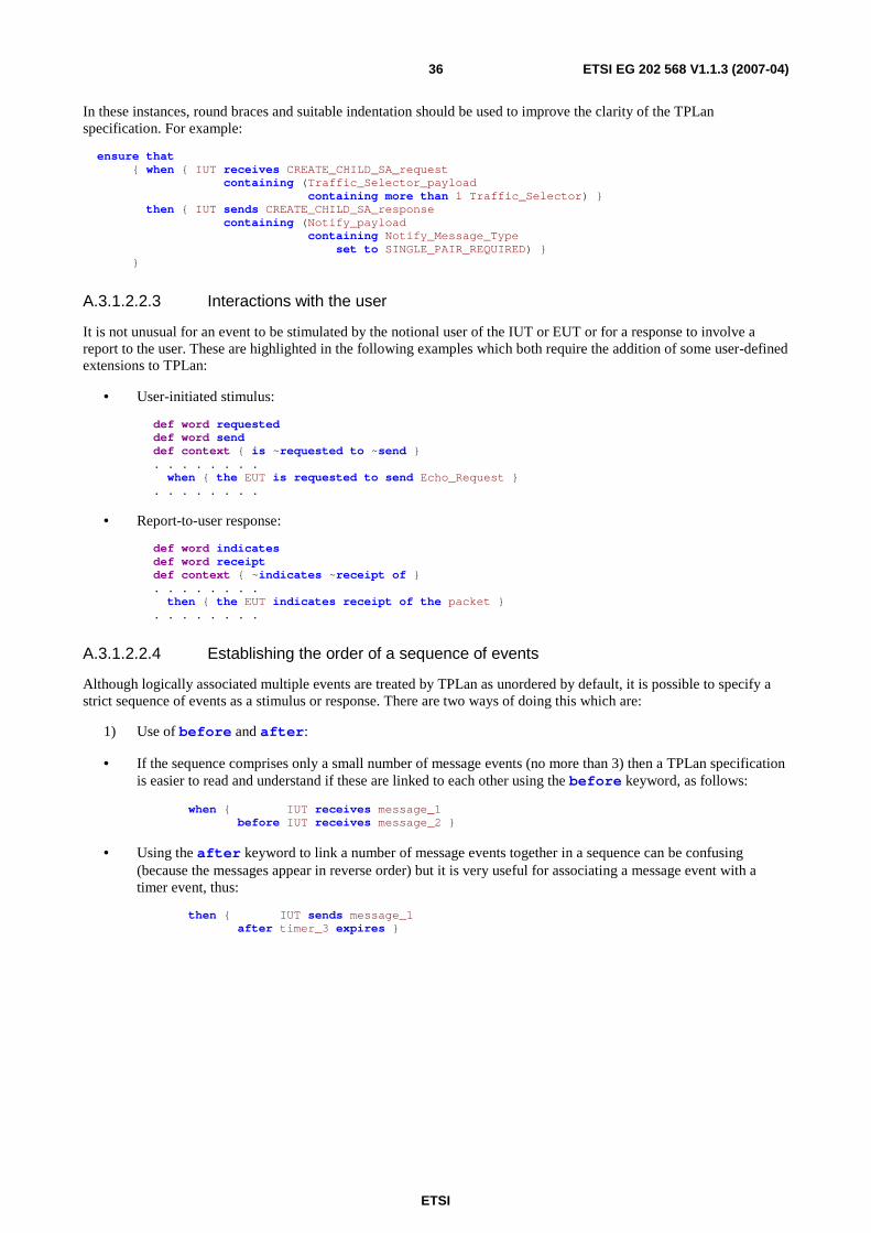
ETSI
ETSI EG 202 568 V1.1.3 (2007-04) 36
In these instances, round braces and suitable indentation should be used to improve the clarity of the TPLan specification. For example:
ensure that { when { IUT receives CREATE_CHILD_SA_request containing (Traffic_Selector_payload containing more than 1 Traffic_Selector) } then { IUT sends CREATE_CHILD_SA_response containing (Notify_payload containing Notify_Message_Type set to SINGLE_PAIR_REQUIRED) } }
A.3.1.2.2.3 Interactions with the user
It is not unusual for an event to be stimulated by the notional user of the IUT or EUT or for a response to involve a report to the user. These are highlighted in the following examples which both require the addition of some user-defined extensions to TPLan:
• User-initiated stimulus:
def word requested def word send def context { is ~requested to ~send } . . . . . . . . when { the EUT is requested to send Echo_Request } . . . . . . . .
• Report-to-user response:
def word indicates def word receipt def context { ~indicates ~receipt of } . . . . . . . . then { the EUT indicates receipt of the packet } . . . . . . . .
A.3.1.2.2.4 Establishing the order of a sequence of events
Although logically associated multiple events are treated by TPLan as unordered by default, it is possible to specify a strict sequence of events as a stimulus or response. There are two ways of doing this which are:
1) Use of before and after:
• If the sequence comprises only a small number of message events (no more than 3) then a TPLan specification is easier to read and understand if these are linked to each other using the before keyword, as follows:
when { IUT receives message_1 before IUT receives message_2 }
• Using the after keyword to link a number of message events together in a sequence can be confusing (because the messages appear in reverse order) but it is very useful for associating a message event with a timer event, thus:
then { IUT sends message_1 after timer_3 expires }

ETSI
ETSI EG 202 568 V1.1.3 (2007-04) 37
2) Use of the ordered keyword:
• When there are a larger number of events in a sequence, these should be specified using the ordered keyword. Although this results in poorer English phrasing, it is considerably less complex than a long series of events linked together with either before or after:
when { ordered ( IUT receives message_1 and IUT receives message_2 and IUT receives message_3 and IUT receives message_4 and IUT receives message_5 ) }
• Round braces should always be used to indicate the extent of the ordered sequence. For example, the when statement above specifies a stimulus which is not the same as the stimulus specified in the following TPLan:
when { ordered ( IUT receives message_1 and IUT receives message_2 and IUT receives message_3 and IUT receives message_4 ) and IUT receives message_5 }
A.3.1.2.2.5 The "do nothing" response
When the expected response to a particular stimulus is to do nothing, user-defined extensions should be specified so that a clear statement can be made, thus:
. . . . . . . . def event response def context { sends no ~response } . . . . . . . . . . . . . . . . then { IUT sends no response }

ETSI
ETSI EG 202 568 V1.1.3 (2007-04) 38
Annex B (informative): Bibliography: ETSI ES 201 873-10 (V3.1.1): "Methods for Testing and Specification (MTS); The Testing and Test Control Notation version 3; Part 10: TTCN-3 Documentation Comment Specification".
ETSI ES 202 553 (V1.1.1): "Methods for testing and Specification (MTS); TPLan: A notation for expressing test Purposes".

ETSI
ETSI EG 202 568 V1.1.3 (2007-04) 39
History
Document history
V1.1.3 April 2007 Publication


![GETVPNG-IKEv2...clientprotocolgikev2ikev2_profile1]–ConfigurethistostartusingG-IKEv2 cryptomapGETVPN_CM10gkm setgroupg1 interfaceg0/0/0 cryptomapGETVPN_CM GETVPN G-IKEv2 Configuration](https://static.fdocuments.us/doc/165x107/5f496b5958b2ce6b8b66e36a/getvpng-ikev2-clientprotocolgikev2ikev2profile1aconfigurethistostartusingg-ikev2.jpg)