Efficient Pulse Width Modulation LED Headlight Driver
81
1 Efficient Pulse Width Modulation LED Headlight Driver A Major Qualifying Project submitted to the Faculty of WORCESTER POLYTECHNIC INSTITUTE in partial fulfillment of the requirements for the degree of Bachelor of Science by Brendan Cavanagh Nathaniel Keahi Goodale Matthew Janiga Date: April 30, 2015 Stephen Bitar John McNeill NECAMSID/Analog Labs Worcester Polytechnic Institute This report represents work of WPI undergraduate students submitted to the faculty as evidence of a degree requirement. WPI routinely publishes these reports on its web site without editorial or peer review. For more information about the projects program at WPI, see http://www.wpi.edu/Academics/Projects.
Transcript of Efficient Pulse Width Modulation LED Headlight Driver

1
Efficient Pulse Width Modulation LED Headlight Driver
A Major Qualifying Project
submitted to the Faculty of
WORCESTER POLYTECHNIC INSTITUTE
in partial fulfillment of the requirements for the
degree of Bachelor of Science
by
Brendan Cavanagh
Nathaniel Keahi Goodale
Matthew Janiga
Date:
April 30, 2015
Stephen Bitar
John McNeill
NECAMSID/Analog Labs
Worcester Polytechnic Institute
This report represents work of WPI undergraduate students submitted to the faculty as evidence of a degree
requirement. WPI routinely publishes these reports on its web site without editorial or peer review. For more
information about the projects program at WPI, see http://www.wpi.edu/Academics/Projects.

2
TABLE OF CONTENTS
TABLE OF CONTENTS .............................................................................................................................................. 2 TABLE OF FIGURES ................................................................................................................................................. 3 LIST OF TABLES ...................................................................................................................................................... 4 PROBLEM STATEMENT ........................................................................................................................................... 5 ABSTRACT .............................................................................................................................................................. 5 ACKNOWLEDGMENTS ............................................................................................................................................ 6 CHAPTER I: INTRODUCTION ................................................................................................................................... 6 CHAPTER II: BACKGROUND .................................................................................................................................... 9
CURRENT MARKET AND MANUFACTURERS ....................................................................................................................... 10 HEADLIGHT LIGHTING TECHNOLOGY COMPARISON ............................................................................................................. 12 CURRENT CONSIDERATIONS AND DRAWBACKS OF LED LIGHTING .......................................................................................... 14 ECOLOGICAL IMPACT OF DIFFERENT BULB TYPES ................................................................................................................ 18 POWER COMPARISON OF BULB TYPES .............................................................................................................................. 20 EXTERNAL AUTOMOTIVE LIGHTING .................................................................................................................................. 21 INTERIOR AUTOMOTIVE LIGHTING ................................................................................................................................... 24 LED NOTIFICATION APPLICATIONS .................................................................................................................................. 25 ARCHITECTURAL APPLICATIONS....................................................................................................................................... 25 CAR ELECTRICAL SYSTEM ............................................................................................................................................... 26 LED HEADLIGHTS ........................................................................................................................................................ 27 HIGH POWER LEDS ...................................................................................................................................................... 30 LED DRIVER CIRCUITS .................................................................................................................................................. 32 DEPARTMENT OF TRANSPORTATION HEADLIGHT REQUIREMENTS .......................................................................................... 34 HEADLIGHT HEAT CONSIDERATIONS ................................................................................................................................ 37 LED HEADLIGHT HEAT DISSIPATION DESIGN ..................................................................................................................... 40
CHAPTER III: PROCESS .......................................................................................................................................... 44
BACKGROUND RESEARCH .............................................................................................................................................. 45 FIRST CIRCUIT EVOLUTION ............................................................................................................................................. 47 SECOND CIRCUIT EVOLUTION ......................................................................................................................................... 49 THIRD CIRCUIT EVOLUTION ............................................................................................................................................ 50 FOURTH CIRCUIT EVOLUTION ......................................................................................................................................... 52 FIFTH CIRCUIT EVOLUTION ............................................................................................................................................. 53 SIXTH CIRCUIT EVOLUTION............................................................................................................................................. 57
CHAPTER IV: RESULTS .......................................................................................................................................... 59
CIRCUIT DISCUSSION .................................................................................................................................................... 59 SPECIFICATIONS & OSCILLOSCOPE ................................................................................................................................... 60 STARTUP ISSUE ............................................................................................................................................................ 62 COMPARISON TO HALOGEN ........................................................................................................................................... 63 EFFICIENCY AND POWER LOSSES ..................................................................................................................................... 64 PRINTED CIRCUIT BOARD ............................................................................................................................................... 65 LED & HEATSINK MOUNTING ........................................................................................................................................ 66
CHAPTER V: FUTURE IMPROVEMENTS ................................................................................................................. 68 CHAPTER VI: CONCLUSION ................................................................................................................................... 70 BIBLIOGRAPHY ..................................................................................................................................................... 73 APPENDIX A ......................................................................................................................................................... 77 APPENDIX B ......................................................................................................................................................... 81

3
TABLE OF FIGURES
Figure I : Bulb phase environmental impact (Lighting European Lamp Companies Federation,
2009) ............................................................................................................................................. 16
Figure II : Kelvin color temperature scale (HubPages, 2011) ...................................................... 17 Figure III : Office environment color temperatures (HubPages, 2011) ........................................ 17 Figure IV : Light level at varying distances from source (Speedster Source, 2014) .................... 21 Figure V : Automobile light placement ........................................................................................ 24 Figure VI : Automobile power system (Firestone, 2014) ............................................................. 27
Figure VII : LED VI characteristics (Thomas & Pforr, 2009) ...................................................... 29
Figure VIII : Example LED array (Thomas & Pforr, 2009) ......................................................... 30 Figure IX : AC voltage LED array (Thomas & Pforr, 2009)........................................................ 30
Figure X : XP-L LED typical forward voltage and current (CREE) ............................................ 31 Figure XI : Buck converter (Diodes Incorporated, 2010) ............................................................. 33 Figure XII : Buck converter adjustable application (Diodes Incorporated, 2010) ....................... 34 Figure XIII : Headlamp upper beam specifications (USDoTNHTSA, 2004) .............................. 36
Figure XIV : Vertical & horizontal headlamp angles (Society of Automotive Engineers, 2010) 37 Figure XV : Thermal cycle testing (Society of Automotive Engineers, 2010) ............................ 39
Figure XVI : LED Lamp reflection for high and low beams (Koester, 2010) .............................. 41 Figure XVII : Lamp diagram (Koester, 2010) .............................................................................. 42
Figure XVIII : Heat pipe diagram (Rice, 2004) ............................................................................ 43 Figure XIX : First Circuit Evolution Schematic ........................................................................... 48
Figure XX : Transient Analysis of Circuit I ................................................................................. 49 Figure XXI : Second Circuit Evolution Schematic....................................................................... 50 Figure XXII : Third Evolution Schematic .................................................................................... 51
Figure XXIII : Transient Analysis Circuit III ............................................................................... 52 Figure XXIV : Fourth Circuit Evolution Diagram ....................................................................... 53
Figure XXV : IC Comparison Chart ............................................................................................. 54 Figure XXVI : IC Application Circuit .......................................................................................... 55 Figure XXVII : Breadboard IC Circuit ......................................................................................... 56
Figure XXVIII : IC Breakout Board ............................................................................................. 57
Figure XXIX : Sixth Circuit Evolution ......................................................................................... 58
Figure XXX: Final Circuit Schematic .......................................................................................... 59 Figure XXXI: Normal Operation CH1 (input voltage), CH2 (gate voltage), CH3 (load voltage) 61 Figure XXXII: Startup Delay Capture .......................................................................................... 63
Figure XXXIII: PCB Layout ........................................................................................................ 66 Figure XXXIV: PCB Rev 01 ........................................................................................................ 66 Figure XXXV: LED Mount & Heatsink ....................................................................................... 67 Figure XXXVI: LED Headlight Operational ................................................................................ 68

4
LIST OF TABLES
Table 1 : Bulb lifespans (autoevolution, 2014) ............................................................................. 15 Table 2 : Bulb type lumens and power usage ............................................................................... 21
Table 3 : Headlamp lower beam specifications (Society of Automotive Engineers, 2010) ......... 36 Table 4: Design Specifications ..................................................................................................... 60 Table 5: Halogen v. LED .............................................................................................................. 64

5
PROBLEM STATEMENT
Automotive headlight technology has lagged behind other technological adoptions used
in vehicles. Most automotive headlights are essentially the same as they have been for the past
five decades, utilizing incandescent halogen bulbs. This technology converts almost 90% of its
energy into heat rather than light, and has a shorter life time compared to the alternatives
available today. LED headlights are emerging in the marketplace on high end vehicles and
aftermarket conversion kits. However, incandescent bulbs hold the majority of market share
since they are made in large quantities, cheap and quick to manufacture, and offer satisfactory
lighting characteristics. LED headlight technology is attractive since it boasts higher efficiency,
resulting in higher MPG, extends the range of electric vehicles, longer lifespan than traditional
bulbs, and provides more effective luminescence. These headlamps require a proper LED driving
circuit, ease of installation, provide sufficient light to illuminate the road, maintain price
comparable with that of traditional incandescent halogen bulbs. Unlike typical bulbs, LEDs do
not radiate significant amounts of heat, leading to potential ice accumulation on the headlight
cover glass. This paper concentrates on the use of pulse-width modulation for increased lumen
output with greatly reduced power consumption.
ABSTRACT
LED headlights can provide better luminescence and less power consumption when
compared to traditional halogen headlights. The adoption of LEDs in automobiles has been slow
as the technology is more expensive than halogen bulbs, more complex to integrate, and
younger. As such, an efficient, simplistic, and easy to use illumination driver was developed to
spur on the widespread adoption of LED use in automobile lighting. The circuit developed is

6
capable of providing the necessary illumination for a fraction of the energy input required by
traditional lighting.
ACKNOWLEDGMENTS
We would like to thank Professor Bitar, our main advisor, for all the help and guidance
he provided throughout the year. His help was instrumental in the development of this project as
and the successful completion of the circuit. We would also like to thank our co-advisor
Professor McNeill as well as our sponsor NECAMSID. A special thanks to Bob and Bill from
the ECE shop for their willingness to provide us with materials and help us fashion components.
CHAPTER I: INTRODUCTION
The desire for energy efficiency has spurred on a new drive in industry to produce
products that consume as few resources as possible to operate. Traditional lighting techniques
such as halogen bulbs have been the focus of some of these efficiency improvements. Almost
90% of the energy consumed by a halogen bulb is converted into heat rather than visible light
(autoevolution, 2014). In the home, U.S. power companies have started to phase out
incandescent lights in favor of CFLs (Compact Florescent Lights) and LED lighting (Light
Emitting Diodes). Not only has the home seen pushes for improved lighting efficiency but so
hasn't the automotive industry. As gas prices increase and the consumers’ desire for greater MPG
increases with it, automakers have taken to improving the efficiency of their illumination
systems. By switching to LED lighting for a car’s headlights, interior lights, running lights,
indicators, etc. auto manufacturers can reduce energy consumption and advertise a higher MPG
as well as boast environmentally friendly improvements. Currently, the integration of LED bulbs

7
into headlights is typically seen only in electric vehicles and high end cars. However, recently
announced cars such as 2015 Ford F150 will be the first pickup truck to offer a full forward LED
illumination system. Currently, halogen bulbs and Xenon HID’s have the majority of market
share, but as LED technology and ease of integration improve they will begin to take a greater
portion of the market.
LEDs are far more efficient than traditional bulbs at generating light. Unlike
halogen/incandescent bulbs, most of the energy is converted directly into light rather than waste
heat. One reason LED headlights can be vastly more efficiency is by using pulse width
modulation (PWM) to control the amount of light emitted. PWM works by turning the LED on
and off at a frequency faster than the eye can see. PWM uses something called a duty cycle. Duty
cycle determines what percentage of the time the power should be off. A 50% duty cycle would
mean 50% of the time the power is on and 50% of the time the power is off. If an LED were
driven with a constant voltage and then switched to a 50% duty cycle PWM driver, its efficiency
would double. This is because 50% of the time the LED would technically be off. However, the
frequency is such that the human eye cannot perceive this flickering. This is how a computer
monitor operates, the screen is actually refreshing 60 times per second but we would never be
able to notice it with the naked eye. By finding the correct frequency and duty cycle, the
brightness and increased power efficiency can be achieved. Another aspect traditional halogen
bulbs suffer in is dimming applications. When dimming a traditional bulb, an adjustable resistor
is put in series with the bulb to vary the voltage over the bulb, this in turn adjusts the amount of
light emitted. Thus dimming a traditional bulb does not reduce the expended energy. However,
dimming an LED works as intended, a more dim light will use less power and PWM can be used
to do this.

8
The team’s focus on automobile headlights is due to the unique nature of cars versus a
stationary object plugged into an outlet. Cars consume electrical energy from the battery which
consumes gasoline from the tank. Anything that drains more power from the battery will cause
more gasoline consumption to allow the car to charge itself. Headlights are massive consumers
of this energy from the battery. Halogen headlights draw upward of 50 watts per bulb. This
power draw can be dramatically reduced by using LED bulbs which only take around 15W per
bulb. Another advantage to LED bulbs is their longevity, as they last tens of thousands of hours
compared to the average of only one thousand hours for halogen headlights.
Tesla, Toyota, and Audi are leaders in the field of integrating LED headlights, being
some of the early adopters of the technology. LEDs were first adopted by Audi in a high profile
manor because of their form factor and unique look. As LEDs are small, and arrays can be used
to generate the required light, they can be made in various shapes and sizes. This appealed to the
auto manufacturers as it allowed them to mold custom light housings into their vehicles. The
LEDs also proved to be brighter and easier to mold into the desired light pattern for headlights
than halogen bulbs used in the past. Along with the advantages of light brightness and design
manipulation qualities of LEDs, Tesla and Toyota integrated LEDs to save on battery power.
Now this battery could be preserved thus increasing MPG and extending the range of the vehicle
or allowing additional features. Tesla and Audi are of course high end automakers, however we
have seen slow adoption of LEDs into a more reasonable line of automobiles. Most hybrid or
electric vehicles use LEDs as electrical power consumption is even more important than before.
They are also being installed by end users in order to give them the lumen output they want or
improve their cars efficiency.

9
There are several manufactures that are currently producing high power LED drivers that
are able to power LEDs for headlights in vehicles. Allegro, TI, Rohm, and LT all produce these
chips. However, with the exception of Allegro, the chips are far more complicated than they need
to be, with multiple uses and setup configurations possible with each chip. This over complexity
and feature recycling leads to inefficiency, higher price, more failure points, and more a complex
understanding required. The aim of this project team was to develop a simple high power LED
driver for headlights using pulse width modulation. If an easy to understand, effective, cheap, but
extremely efficient driver could be developed, it might help ease the integration of LED’s into all
applications, specifically headlights.
CHAPTER II: BACKGROUND
As of 2014 the market for light emitting diode (LED) lighting in both the automotive and
household industries is rapidly growing to incorporate increasingly efficient and effective
products and techniques. In 2011 the LED market as a whole grew by 10%, while the use of
LED’s in the lighting sector grew by an astonishing 44% (LEDs Magazine, 2011). With this it is
clear there is demand for practical, energy efficient, LED lighting options within the automotive
industry. According to some, there is an expected compound annual growth rate (CAGR) of 34%
for LED headlights alone, as the automotive industry reaches towards converting all front-end
lighting to either Xenon high intensity discharge lamps (HID) or LEDs in a motion to reduce
costs and increase MPG (miles per gallon) (LEDs Magazine, 2011). The automotive industry is
going through a transitional period where manufacturers are slowly incorporating LED
headlights into cars by creating headlight hybrids. The low beam of the car is reserved for the
LEDs as they are more reliable, longer lasting, and more energy efficient. Whereas the high

10
beams are implemented with halogen lamps or Xenon HIDs for increased brightness and
distance. Currently, LEDs are produced by several major manufacturers like General Electric
(GE), Philips, Osram Sylvania, and Cree.
Current Market and Manufacturers
In 2012, the global market for LED lighting was estimated to be around $4.8 billion and
is projected to grow to $48 billion by 2019(LEDs Magazine, 2011). With LEDs holding an ever-
increasing market share in the lighting industry, major manufactures and small startups have
started to capitalize on this growth. GE produces various types of lighting and has been
producing consumer-level LEDs for a while. Their applications are seen within most industries
where lighting is needed. Specifically, GE’s line of premium NIGHTHAWK™ LED headlights
have become a staple in many aftermarket headlight installations. As will be discussed later,
these headlights claim to produce light that is closely matched with the color spectrum of
average daylight. Meanwhile, a company by the name of Hella is now responsible for producing
all LED headlights that are standard on Audi’s A8, A6 and A3, Cadillac’s Escalade, the
Mercedes E-Class and a DAF truck (LEDs Magazine, 2011).
Companies like Philips produce LED headlights but have focused primarily on their
home and office lighting applications. Philips’ Xenon HID headlights and standard halogen
lamps are there most popular headlight as these two styles currently hold the largest market
share. As of right now, the majority of LED headlights are used on luxury cars that try to get
ahead of the current market and into the next trend. This is likely because right now, LED
headlight technology and implementation is in its infancy compared to standard halogen bulb
technology or even the growing Xenon market. Major companies like Philips and GE can

11
produce great LEDs, based on electrical principles, but they may not make the best headlights
which rely on light reflection and diffraction technology. As such, several smaller companies
like NewBrights and several start-ups have come into the market to buy LEDs from major
manufacturers and implement them in new ways using these lighting techniques. However, LED
lighting in general has gotten a strong footing as the Toyota Prius, a car reliant on electricity and
efficiency, has chosen LEDs for many of its lighting applications. Additionally, the first pick-up
truck with LED headlights will be the 2015 Ford F-150, it will be using one LED bulb for both
high and low beams (Williams, 2014).
The market is currently dominated by halogen lamps as they have become the cheapest to
implement, have a long life, and offer good lighting characteristics in balance with the driver and
oncoming traffic. As this lamp technology has been around for so long and production costs have
become very low, automotive manufacturers have preferred this style of light. However, their
power efficiency is a big drawback, leading some manufacturers to look for more energy
efficient solutions to increase their MPG. This led to a successful introduction of Xenon HIDs,
which claimed higher energy efficiency and a brighter light which can then be used by
manufacturers in car safety advertising. Traditional halogen bulbs can produce roughly 1400
lumens and 30 mcd/m2 (millicandela per meter squared) whereas Xenon lights are advertised at
3000 lumens and 90 mcd/m2 (autoevolution, 2014). Xenon lights are estimated to have almost
doubled the lifetime of traditional lamps. The specific technologies and power consumption
factors will be discussed later in this paper.
Most recently, LED headlights have entered the market of automotive lighting
applications. The main advantage is clear, they are the most energy efficient solution so far. As
this will lead to an increase in MPG, auto manufacturers have LEDs on the horizon as a potential

12
big evolution within the automotive industry. With current LED technology, the lumens
produced are roughly equivalent to that of Xenon HIDs. So why hasn’t the LED been adopted as
the main source of lighting for cars? Currently, the technology is new, developing in efficiency,
and not yet produced in large enough quantities to offer better value. This drives the cost
upwards to a point it is still more expensive than halogen or Xenon. There are also not enough
manufacturers or variations in the LED headlights offered so implementation into new car
models is expensive, time consuming, and could even require a physical redesign (autoevolution,
2014).
Headlight Lighting Technology Comparison
By the 1920’s electrical lights commonly appeared on automobiles to enable the driver to
better view the road and for other drivers to better see the vehicle. Today there are three main
types of bulbs used in automobiles: incandescent tungsten-halogen bulbs, high-intensity
discharge lamps, and LEDs. Incandescent tungsten-halogen are the most common bulbs used in
automobiles and are the simplest way of producing the necessary light, emitting about 800-1000
lumens (lm). This type of bulb is preferred because they are simplistic, cheap to make, and are
easy to replace when the bulbs burn out. However, this type of bulb is not very efficient, with
approximately 90% of the consumed energy being converted into heat and not visible light
(autoevolution, 2014). A HID lamp emits light by creating an arc of electricity spanning across a
quartz-glass tube with a metallic salt compound. This tube reacts with the electricity to create
plasma, emitting light in the process at 2900-3200 lm. These bulbs are more efficient than
incandescent tungsten-halogen bulbs and have a higher average lifespan as well (Table 1). Xenon
lights work in much the same way but use Xenon gas instead of metallic salts. One of the

13
drawbacks of both HID and Xenon technology is the high amount of heat produced by the bulbs.
LED headlights must be arranged in an array, as one diode is insufficient to produce enough
light. These bulbs, unlike the others discussed, convert the majority of energy directly into light
and not heat. This leads to a drastic increase in efficiency. Many automakers have opted to use
LED technology in taillights because of their quick illumination time, beating out incandescent
lamps by 400-500 milliseconds to give the trailing driver more time to react (autoevolution,
2014).
The technology that produces the least amount of light is the incandescent tungsten-
halogen bulb, producing about 800-1000 lm. HID’s and Xenon bulbs are the brightest at about
2900-3200 lm. This brightness is comparable with that of LED technology. Currently, the
limiting factors of luminescence include headlight housing design and power constraints.
Headlight housings can be complex, as LED is a new technology to car headlights and kinks still
need to be worked out. Power available to the LEDs is limited, as well as the maximum
temperature range they can safely operate.
The lifespan of these different lighting technologies is also very important to take into
consideration when choosing the right bulb to install in a vehicle. The consumer does not want to
be changing the headlight bulb in their vehicle very often, no matter how cheap or easy it is to
replace. Halogen bulbs have a lifespan of roughly 1000 hours, while HIDs/Xenon lamps last
approximately 2500 hours, and some LED headlights have claims of up to 15,000 hours of
operation (autoevolution, 2014).
Cost is an important factor when choosing a bulb technology to implement in the design
of an automobile. As with other older technology, the halogen bulb is the cheapest to implement,
produce and install. This is because it has been in use for a long period of time and is a very
14
simple system to build and implement. With HIDs, LEDs, and Xenon lights, cost becomes a
factor. These technologies are much more complex, require more expensive parts, and a more
involved manufacturing process.
One of the main advantages of LED headlights it that they are small. This allows a
greater manipulation of design and placement. LEDs possess a well-established efficiency
advantage over the other lighting technologies, with nearly all of the input energy going directly
to photon production, with very little being converted into heat. LEDs possess the longest
operating-life of any of the technologies discussed previously. However, LEDs have a higher
production cost and tend to produce less light when exposed to higher temperatures. One
problem that designers face when implementing LEDs is that they tend to produce heat at their
base that can affect adjacent components; a thermal regulatory system must be taken into account
in the design process.
Current Considerations and Drawbacks of LED Lighting
The main attraction of utilizing LED technology is the energy saving potential offered by
the technology as they convert roughly 80% of energy into light. As previously discussed, LEDs
have a much longer operating life than that of other bulb varieties, upwards of 15,000 hours of
operation for a car headlamp and upwards of 100,000 hours of operation for other fixtures. This
helps to mitigate the upfront cost of purchasing the more expensive LEDs. With the longer
lifespan and little toxic chemicals that go into LEDs, they are a much more ecologically friendly
choice. See Figure I and Table 1 to view ecological effects related to the life cycle of the bulb
and equivalency comparisons. With their small size, many design configurations are possible.
LED systems also have the ability to be easily dimmed, unlike florescent systems.

15
However, there are disadvantages with using LED lighting technology. LED lights are
much more expensive than more traditional methods of lighting. This can put people off from
buying LED lights as the upfront investment is too expensive. This is especially true of
people/companies that have adopted florescent lighting because there is less energy saving
difference to incentivize the adoption of LED lighting systems. There is a temperature
dependence for the LEDs, without an adequate heat sink, the ambient temperature of the
environment combined with the heat produced by operation can be enough to result in failure of
the system. This is especially important to take into consideration when planning for use in the
automotive setting. When utilizing LEDs for light, it is also necessary to consider the voltage
threshold and the current ratings of the diodes in question. A specific voltage must be maintained
for optimal light emission, and below the current threshold so as to not damage the diode and
maintain its efficiency.
Type of Bulb Lifespan Equivalent replacement
bulbs to equal LED
Halogen ~1,000 hours 15
HID/Xenon ~2,500 hours 6
LED >15,000 hours 1
Table 1 : Bulb lifespans (autoevolution, 2014)

16
Figure I : Bulb phase environmental impact (Lighting European Lamp Companies Federation,
2009)
There are several different types of LEDs that are used for colorful aesthetics: Red-
Green-Blue (RGB), Red-Green-Blue-Amber (RGBA), and Red-Green-Blue-White (RGBW).
These systems combine different LED colors to recreate any color and hue by varying the
intensity of the different colors. This is most commonly done with RGB combinations, but as a
color LED has a very limited wavelength spectrum that is emitted, some colors do not come out
as well as others. This issue has been mitigated by adding a fourth color to the array, amber, to
create a RGBA light system. The amber helps to fill in missing wavelengths, leading to more
realistic color reproduction. Another system was created to allow white LEDs to be used
independently, the RGBW system. This allows for the regular RGB color combinations as well
as the ability to mix in white light to any of the color combinations or as a standalone.
White LEDs can lead to color distortion when compared with natural light. Many white
LEDs produce a cool blue light that does not bring out the brighter colors of objects. The
temperature of the light can be described as “warm white”, “natural white”, or “cool white”. This

17
temperature of light is measured in a Kelvin Color Temperature scale, ranging from 1,000K for
red to 10,000K for blue sky. This can be seen in Figure II. The difference hues of light in an
office environment can be seen in Figure III.
Figure II : Kelvin color temperature scale (HubPages, 2011)
Figure III : Office environment color temperatures (HubPages, 2011)

18
Ecological Impact of Different Bulb Types
Halogen/Incandescent
Halogen bulbs create an immense amount of heat when operating. This requires that the
housing of the bulb itself be able to retain enough heat for the system to function properly
(250OC) but also displace enough heat so that the system does not melt. If the bulb is too cool,
the system will break down and eventually fail.
These bulbs are relatively easy to manufacture. They only require glass, a tungsten
filament, and a halogen gas. This leads to a cleaner manufacturing process. The tungsten infused
coil of the filament is made by winding a wire to create better light emission characteristics. The
glass is first formed to fit over the filament and then attached to the housing. Then the mount is
made by running the tungsten wires through a quartz rod to fix the system in place. The bulb is
then sealed by pumping an inert gas such as nitrogen or argon into the housing to flush out any
other gases. While this is happening the bulb is being heated and hermetically sealed. A small
amount of halogen gas is placed inside each bulb. The bulb is then permanently sealed after the
electrodes are attached securely to the base (MadeHow, 2014).
HID/Xenon
Xenon use less energy than that of traditional halogen lamps, resulting in less fuel
consumption. The components of an HID are as follows: a mixture of noble (Xenon) gasses or
metal halide salts, two electrodes, inner quartz housing, and outer quartz housing. There are three
things that affect quality and performance of these bulbs: the purity of the noble gas or metal
halide salts affects color and consistency, the arc electrode that seals the halogen gas mixture

19
from leaking out, and the quality of the quartz can affect the amount of UV light emitted as some
is filtered out (HID Extra, 2014).
LED
Diodes are made with very thin layers of semiconductor material, and impurities in these
materials are used to create a specific electron density. The semiconductor material that is used
to manufacture LEDs is gallium arsenide, gallium phosphide, or gallium arsenide phosphide. The
different levels of impurities in these semiconductors allow for different colors of light to be
produced from the diode. Note: These are impurities, not imperfections and are the intentional
result of doping the material for a desired result. The doping consists of adding zinc or nitrogen,
and more rarely silicon, germanium, or tellurium. The LEDs are covered in a transparent plastic,
it is this plastic that determines the light refraction pattern emitted and if tinted, can alter the
color of the light (MadeHow, 2014).
Corollaries
From this information, we can see that the materials and manufacturing that goes into
these bulbs does not stand out as more or less environmentally harmful than others. However, if
taken strictly from a manufacturing perspective the halogen bulbs would be the most
environmentally friendly as they are the simplest to make. When taking HID/Xenon into
account, the manufacturing process is much more involved but not directly harmful to the
environment. As for LEDs, they have the most complex and precise characteristics of these
technologies and require the use of semiconductor materials. However, these materials are used
in small quantities. When taking into account usage, replacement rate, and disposal, LED
20
technology leads the way in being environmentally friendly. Please refer back to Figure I. This
shows that most of the energy and environmental degradation that results from a bulb in its
lifetime is because of its use. This totals to about 90% of a bulbs environmental impact. With this
in mind, LED technology leads the way in being environmentally responsible because it uses the
least amount of electricity.
Power Comparison of Bulb Types
Halogen headlights consume about 55 watts of electricity to produce approximately 1,400
lumens per bulb. This is equal to 52.45 lumens/watt (autoevolution, 2014). When compared with
HID/Xenon and LED technology, the energy usage is dramatically different. For HID/Xenon, the
bulb produces 85.71 lumens/watt for each bulb. This is a significant amount more light emitted,
with far less power usage. LEDs produce 88 lumens/watt for each light fixture (GTR Lighting,
2014). This is only slightly more than that of HID/Xenon; however at the 3,000 lumen intensity
it is possible to blind other drivers on the road with the excessive amount of light. It is also
important to remember that every extra watt of power that goes into using the headlights is
coming from the fuel tank, thus more power being used lowers the fuel economy. These power
ratings are for each bulb, and with a bulb on each side of a car the power usage must be doubled.
Thusly, halogens use 110 watts, HID/Xenon use a total of 70 watts, and LEDs use 50 watts.
Table 2 shows concise power comparisons between bulb technologies. This saved energy in an
electric vehicle can be used to extend the range and reduce the frequency of charging, especially
if all lighting in the car were to be LED.
LED headlights produce a clearer and more forward facing cone of light where it is
needed by the driver. HID/Xenon lights produce a brighter and wider beam of light compared

21
with the LEDs. When compared side by side, the LED lamps appear brighter and less “blue” in
color, as they offer a whiter light. Halogen lights fall far behind HID/Xenon lamps and LED
lamps. According to a MotorTrend side-by-side comparison, the Halogen lights offered inferior
illumination of the road. When the authors of this article switched back to halogen they claimed
it was as if there was a safety hazard from not having enough illumination of the roadway. Figure
IV shows the lighting characteristics of halogen bulbs versus HID.
Figure IV : Light level at varying distances from source (Speedster Source, 2014)
Lumens Watts Lumens/Watt
Halogen 1400 55 52.45
HID/Xenon 3000 35 85.71
LED 2200/2600 28 88
Table 2 : Bulb type lumens and power usage
External Automotive Lighting
Lighting on the exterior of automobiles has been developing over the last century,
beginning with the first headlamp bulbs in 1908 (Wordenweber, 2007, p.96). A major
development for exterior lighting occurred in 1960 when the first halogen light source was

22
introduced in European vehicles (1979 in the US). Only twenty years ago the replaceable
headlamp was introduced. Already consumers have an assortment of choices varying beyond
incandescent, HID bulbs, and most recently light emitting diodes.
Modern vehicles have a number of components that make up headlamps. It is standard
that these encasings sit between a height of 500 and 1200mm from the road’s surface
(Wordenweber, 2007, p.97). Inside the headlight unit are multiple bulbs which include the low
beams, position, indicator, main beams, fog lights and running lights. The purpose of the low
beams, also known as dipped beams, is to allow for a wide field of vision without hindering
oncoming drivers (Wordenweber, 2007, p.99). Because of this, the dipped beams are designed
with a light cut-off angle of 15 degrees with respect to the right curb. This means that above this
angle from the curb, the amount of light diminishes rapidly. Additionally, these beams are angled
slightly towards the ground so that light is directed downwards by 1%. This has the effect of
allowing low beams to project only about 60m into the opposing lane while allowing the driver
up to 120m of visibility in his or her own lane. High beams, or main beams are implemented into
the headlight unit for the best possible range in low to no traffic driving situations
(Wordenweber, 2007, p.100). Since these beams are not intended for use around other motorists,
the direction of light does not need to be directed downwards. Rather the light is projected with a
+- 10 degrees angle. Fog lights are angled even more than low beams tilting the light downwards
by 2%. This allows for best visibility up to 35m in front of the car. The +- 35% horizontal beam
width also adds to this close range visibility. Indicator, position, and daytime running lights are
not used for the operator’s benefit but rather for other motorists to increase visibility and reduce
uncertainty.
The headlamps used in the automotive industry utilize either reflection or projection

23
technology. Reflection technology is recognizable due to the reflectors behind the lens making it
more distinguishable. This type of system works based on the shape of this reflector and patterns
on the cover lens (Wordenweber, 2007, p. 101). These features are used to bend and manipulate
the light in the desired direction for best optical performance. In a projection system, light from a
source is passed through an elliptical reflector that is in the lens’ focal plane (Wordenweber,
2007, p. 102). A shield covers this reflector and is used to shape the light and produce the desired
cut-off. LED lighting systems can utilize either of these two designs. This offers the possibility
of dynamic lighting and the ability to change light positions and intensities smoothly
(Wordenweber, 2007, p. 110). Nonetheless, as LED lighting in vehicles is still emerging,
designers have to take into consideration limitations such as current draw, the need for drive
circuits, and different methods for heat dissipation.
The first LEDs appeared as brake light strips in the 1990s (Wordenweber, 2007, p. 111).
These were in conjunction with the normal two taillight designs still seen today but incorporated
single red LED strips on spoilers of vehicles. These initial packaged chips could only utilize a
20mA drive current without additional heat sinking. Similar to headlamps, the rear lamps of an
automobile have several different bulbs. These include the rear position lamp, rear lights, brake
lights, rear turn indicator, reversing light, central high mount stop lamp, license plate lights, and
a rear reflex (Wordenweber, 2007, p. 160). The rear position lamp is the constant red light
emitting from the tail lights when the headlights are on. These lights become brighter when the
brake lights are activated and signal to other drivers that the vehicle is slowing down. The rear
turn indicator also signals to other drivers that the vehicle is about to make a turn, and the
reversing light indicates the vehicle will be or is already backing up. The central high mount stop
lamp functions with the brake lights to also indicate that a vehicle is stopping. The rear reflex is

24
not a bulb but rather a reflector that refracts light from a following driver’s headlamps.
Interior Automotive Lighting
The interior of automobile lighting is following the trending technology of exterior
lighting. That is, it is moving toward new sources of light, including LED (Wordenweber, 2007,
p. 185). Only a few years ago car manufacturers started to incorporate more lighting features
than the typical single overhead dome. Most standard and lower grade models still only have this
one dome light. As cars are becoming more sophisticated, so is their interior lighting and the
industry is working to create both aesthetic and useful lamp positions. The image below
demonstrates different examples of light placements in a modern vehicle.
Figure V : Automobile light placement
Unlike exterior lighting, interior vehicle lighting is unregulated. It is important for
designers to consider aspects such as overall brightness, glare and contrast levels, and comfort of
specific color schemes while taking into account how the interior light will affect the driver’s
view out of the vehicle (Wordenweber, 2007, p. 188). The color of interior lighting in vehicles

25
has a mental effect on the human brain. Colors associated with warm temperatures flaunts a
technical ambience while cooler temperatures create a home-like environment. Much of the
current lighting involves entering and exiting features such as sensors that control lights. These
lights may turn on when a door is opened or shut off after a door is closed (Wordenweber, 2007,
p. 196).
LED Notification Applications
Currently, LEDs are being used for various types of notifications and status indicators.
For example, the iPhone has the ability to use the LED meant for the camera flash as a
notification for something like a text message. Other smartphones have a front facing LED that
will light up and stay lit with different colors to indicate different things. These type of concepts
can and have been translated into the automotive industry, not necessarily with LEDs though.
Things like a “check engine” light or a low gas light have, for a while, utilized a simply binary
on or off light to indicate its status. However, there is room for a new form of check engine light
that would be simple, cheap, smaller, and require less resources. A single LED that can change
color to signify different things and then rotate between these notifications if there is more than
one. This would reduce circuitry and therefore price. It would also integrate well with the current
automotive trend of everything being digital, touchscreen, or luminescent versus physical
indications.
Architectural Applications
Philips and Cree are two companies that are leading the architectural industry for LED
retrofitting homes, businesses, and urban environments. Philips has an UrbanScapeTM product

26
line of LED street lights resembling traditional street lamps with more efficiency. An overhead
lamp can house up to 96 LEDs (Phillips, 2014) that can provide 20,000 lumens or equivalently
an HID bulb rated at 400W. Philips has a wide variety of LED lights that come in an assortment
of shapes and sizes depending on the application. Philips does produce LED A-type bulbs which
are typically used in homes. Additionally, they are producing LED bulbs with the same shape as
typical fluorescent tubes (T8 lamps). They advertise these LED lamps as “InstaFit” as they fit in
the place of fluorescent tubes. This is convenient for businesses and other commercial
applications that want to retrofit their lighting systems in a simple way (Philips, 2014).
Cree is also producing a number of LED lights with a wide range of applications such as
Philips. Cree has a number of A-type bulbs that are tailored to residential consumers. An
example of one of these bulbs is their A19 series bulb capable of outputting 1,100 lumens of
light with a 25,000 hour lifetime. The bulbs in the A19 line have power ratings of 6, 9, and
13.5W which are equivalent to 40, 60, and 75W traditional bulbs. The energy savings as well as
increased service life are making LEDs more practical for almost all applications. LEDs are
becoming more common as they are dimmable, more efficient (85% less energy), and can go
several years without replacement (Cree, 2014).
Car Electrical System
The major components of an automotive electrical system include the battery, starter,
alternator, and electrical connections. When the ignition key is turned, the 12V battery provides
power to the starter which begins spinning the flywheel. This wheel is what starts the motion of
the pistons in the engine. The alternator is a crucial feature of the electrical system as it keeps the
system running and the battery charged while the car is operating. Figure VI below shows

27
visually how this intricate process works.
Figure VI : Automobile power system (Firestone, 2014)
This power system for a vehicle is distributed to the various electrical components inside
through the use of a wire harness. The wire harness consists of a network of wires and
connectors to power lights and electronics throughout the car and is traditionally a 12V DC
system (Oba, 2013, p.1). A major concern for these long lengths of cables is weight, especially
with new state of the art cars demanding more electrical terminations for components. A typical
wiring harness in a car can weigh as much as 30 kg and can have an impact on fuel efficiency.
LED Headlights
LED headlights are emerging in the automotive industry for a variety of reasons. One of
the biggest appeals of LED lighting systems is the extended lifetime. When implemented
properly, LEDs should last longer than the lifetime of the vehicle. Other benefits include
increased efficiency, an increase in style, and compactness (Dross, 2005, p.1). However,

28
differences between LEDs and standard bulbs such as incandescent, halogen, and xenon make
the circuit design procedure much different. Average bulbs typically project between 300 and
400lm of light and good bulbs can produce up to 900lm (Dross, 2005, p.2). The standard designs
using reflection and projection technology as described earlier are used to direct the beam of the
bulb. These traditional lighting systems only use one bulb so much of the luminous flux is lost
directing the beam down towards the road. This reduces efficiency to as low as 30-50%.
Although a single LED can only output around 100lm, the angle at which it produces light is
much smaller allowing more efficient design. Since they emit a fraction of light compared to
omnidirectional bulbs, a system of six or more LEDs is typically implemented. Multiple LEDs
can be used in a system to illuminate a field of view for the driver without needing to reduce the
angle of light such as with standard bulbs. This allows LED systems to reach efficiency levels of
up to 80% (Dross, 2005, p.2).
The first automotive LED applications utilized the T-1 ¾ package and were mostly used
in tail lights because current could only reach about 20mA before further heat sinking was
required. By the end of the 1990s newer packages were able to output up to 50mA before
additional heat sinking was required (Wordenweber, 2007, p. 111). Technological advances are
increasing the power capabilities of LEDs and cooling systems need to keep up. Lower junction
temperatures are desirable as an increase in temperature results in reduced light production and
electrical stress that reduces lifetime of the diodes (Lin, 2012, p.1435).
Typical LED headlight circuit designs utilize either linear or switching regulating devices
in order to brighten or dim the lamps. It is common to use a DC/DC converter to achieve this
switching (ROHM Semiconductor, 2014). LEDs may either be connected in a single series string
or multiple strings connected in parallel (Thomas & Pforr, 2009). Connecting smaller strings in

29
parallel allows for a higher current draw than wiring the same number of LEDs in series but also
presents the issue of individual LED parameters and the precision of fabrication. Figure VII
below shows how a small difference in forward voltage of two LEDs can affect the current draw
through a branch of the circuit.
Figure VII : LED VI characteristics (Thomas & Pforr, 2009)
One way to avoid these mismatched parameters is called voltage binning. During
production, LEDs can be sorted more precisely by grouping them with other parts that exhibit
nearly the same forward voltages. However, this is inconvenient and rarely used as it slows down
the production process and thus increases costs. Another way to obtain equal current draw
through each branch involves adding a resistor in series to each string of LEDs (Thomas & Pforr,
2009). Unfortunately, this is not practical for high power applications either as a large voltage
drop must be applied across these resistors to make current deviations smaller. Rather than use
resistors, each branch may utilize a transistor as a current source. This allows for a more
balanced current draw while reducing power dissipation but also increasing circuit intricacy. An
example schematic is shown below in Figure VIII.

30
Figure VIII : Example LED array (Thomas & Pforr, 2009)
Another design involves the use of a sinusoidal voltage source and capacitors in series
rather than transistors. Voltage drops across the capacitors reduce the magnitude of current
deviations through the separate branches. Now that the waveform is AC, more parallel
connections are needed in order to allow current to flow in both directions. An example circuit is
show below in Figure IX.
Figure IX : AC voltage LED array (Thomas & Pforr, 2009)
High Power LEDs
Manufacturers are continuing to develop LEDs capable of outputting higher luminosity.
Several companies including Philips, Cree, and Luxeon are producing high brightness LEDs that

31
are capable of being driven at several amps. These LEDs are also reaching higher efficiencies,
capable of outputting up to 130lm/W (LuxeonStarLEDs, 2014). A particular LED that could be
implemented in an automotive head lighting system is the Cree Xlamp XP-L (Cree, 2014). Cree
produces a line of these LEDs in several colors including multiple hues of white. This line is
attractive as a single LED can be driven at up to 3A to produce a luminous flux of up 1000lm
(Cree, 2014). Figure X below shows the voltage and current characteristics for the XP-L LED.
At the maximum drive current of 3A, the forward voltage is around 3.35V resulting in a power
consumption of about 10W. Referring back to Table 2, a typical halogen bulb consumes 55W
and produces only about 400 more lumens.
Figure X : XP-L LED typical forward voltage and current (CREE)
An advantage of using a high power LED is the freedom of choosing a desired luminous
flux by biasing the current. The datasheet for the XP-L states that a cool white LED will output
620, 776, and 1034lm for respective drive currents of 1.5, 2.0, and 3.0A. This allows for an
endless possibility of designs. For example, a dipped beam can contain two of these surface
mount LEDs in series with a total current draw of 2A. This in turn would produce an output of

32
over 1500lm. The new forward voltage across each diode would be approximately 3.15V
resulting in a total of 12.6W dissipated. Furthermore, each XP-L can be purchased online for
about $6 each at low quantities. Because of this, high power LEDs will be strongly considered
for this project.
LED Driver Circuits
In order to maximize efficiency, the LEDs in a lighting system need to be pulse width
modulated. This requires a DC to DC converter to regulate current draw as well as voltage. DC
to DC converters fall into three categories: buck, boost, buck and boost. A buck converter is also
known as a step down converter since it drives a load at a lower voltage potential than the input
voltage (Buck Regulators Make Diving High Brightness LEDs Easy, 2011). These converters
can reach efficiencies of up 90% or higher with most loss occurring when the active component
is operating. A functional block diagram of Diodes Incorporated AP1509 buck converter is show
in Figure XI followed by an example application in Figure XII (Diodes Incorporated, 2010).

33
Figure XI : Buck converter (Diodes Incorporated, 2010)

34
Figure XII : Buck converter adjustable application (Diodes Incorporated, 2010)
These two figures from the AP1509 data sheet illustrate a possible automotive LED
driver. A 12V car battery can be connected to Vin and R1 and R2 can be picked accordingly to
set the output voltage. The internal circuitry of the IC includes three comparators and an
oscillator to switch between on and off states.
Conversely, a boost converter is used when a higher voltage is needed to drive a load
than what is supplied by the source.
Department of Transportation Headlight Requirements
All innovations in headlight technology must be sure to comply with all Department of
Transportation (DOT) rules and regulations. These regulations safeguard against headlights that,
among other things, could be deemed too bright or pointing at an angle such that the oncoming
driver’s vision is reasonably impaired. Though headlight rules such as what time and in what
conditions headlights must be on can vary by state, there is an overall set of regulations for the

35
specificities and technicalities of all automotive lighting manufacturing. This is the Federal
Motor Vehicle Safety Standard 108 (FMVSS 108) and it’s produced by the United States
Department of Transportation’s National Highway Traffic Safety Administration (NHTSA) in
conjunction with the Society of Automotive Engineers (SAE) and regulation SAEJ1383. These
two standards, covering all automotive lighting, are over 200 pages and is what all automotive
lighting manufacturers must comply with when developing their products.
A sample of some requirements is presented and consists of the following. Note that
certain exclusions and exceptions apply. Any lower beam or high beam headlamps must be
manufactured to produce a form of “white” light, must be of the same height, and symmetrical
about the vertical centerline as far apart from each other as is practical. Regulations state that the
wiring harness must be such that only the light sources intended for meeting lower beam or
upper beam photometrics are energized when the selector switch designates it. The light must be
considered steady and burning except if used in signaling purposes. Specific angle of incidence,
light dispersion, intensity, heat requirements, etc. are all different depending on which type of
headlamp is considered (United States Department of Transportation National Highway Traffic
Safety Administration, 2004). The chart for upper beams follows in Figure XIII.

36
Figure XIII : Headlamp upper beam specifications (USDoTNHTSA, 2004)
For lower beams SAE provides a table seen in Table 3 as rough guidelines to what is acceptable.
Table 3 : Headlamp lower beam specifications (Society of Automotive Engineers, 2010)

37
A general rule most states abide by, found in California’s DOT requirements for lighting angles
states that the emitted light may be no higher than 2 ½ in. below the bulb height at 25 feet from
the car. Certain manufacturers suggest varying changes to this formula, Toyota reduces this
distance to 10 feet, Chrysler 33ft, and most of these are done because headlights and their
housings differs as well as to accommodate larger tolerances as heavy weights in the rear can
increase the vertical angle of the headlights to the road. Figure XIV is taken from SAE J1383 and
provides insights into the vertical and horizontal angle of headlight requirements.
Figure XIV : Vertical & horizontal headlamp angles (Society of Automotive Engineers, 2010)
Headlight Heat Considerations
Traditional headlamps will produce radiated heat when active. This is because in order to
produce light, the filaments and gas within the bulb must be energized thus producing their
luminescence but with a side effect of heat. One very common reason traditional headlamps are

38
often considered inefficient is their large percentage of energy conversion into heat. Almost 90%
of the energy used to light these halogen bulbs is converted into heat rather than light
(autoevolution, 2014). However, this can actually be an asset in certain geographies. For
example, in the United States’ northeast, conditions can become such that snow, ice, and sleet
may accumulate on the housing and lens of the headlight. This heat produced from the bulb will
radiate within the housing, thus heating up the lens. Of course, this will in turn act to melt snow
and ice as well as keep it from forming on the headlights. Without effective headlight wipers,
which have long since been removed as an option on most cars, this can create a situation where
headlights could become ineffective and obstructed. As DOT states, it is the drivers
responsibility and legal obligation to be sure there are no obstructions of emitted light from their
headlights. Without this heat emission, it could cause a seriously dangerous and illegal situation
for some drivers.
To this effect NHTSA and SAE have included in their regulations a thermal profile of the tests
they simulate with headlights. In order for a headlight to pass certification it must succeed in the
thermal cycling that can be found in Figure XV.

39
Figure XV : Thermal cycle testing (Society of Automotive Engineers, 2010)
This figure is simply meant to show the ranges of temperature that these regulatory organizations
might expect a typical headlight to undergo. LED headlights would be subjected to these same
stresses and the same snow and ice conditions any other type of headlight would. This presents
an issue where LED headlights are not producing as much heat as halogen bulbs, thus unable to
melt snow or ice. It also presents an opportunity of how to capture the available heat and utilize
it. In a similar vein, it has been observed that LED traffic lights, if placed in northern climates,
can become encrusted in ice thus inhibiting its proper signaling results. This problem has been
held responsible for several car related fatalities and accidents (Ramde, 2010). Some cities have
had to send public workers around to all traffic lights to melt the ice, a procedure far more costly
than the traditional traffic lights’ inefficiency (Winstrom, 2014). LED headlights face similar

40
issues, if less severe due to the ambient engine heat. This issue has been recognized and there are
currently solutions to mitigate these effects. One such solution is exterior spray nozzles located
beneath the lens. These operate much like the spray nozzles to help wash your windscreen. When
sprayed, the ice will melt much quicker and will also provide a film on the lens that snow and ice
has a hard time attaching to. Some headlights even utilize a heated housing which intentionally
cycles heat within itself to warm up the lens much like halogen bulbs naturally do. Aftermarket
products like Rain-X™ act to create a surface snow cannot stay on and so help to prevent icing
over. As LED headlights are still new to the market, different solutions, techniques, and work-
arounds to produce or capture heat in hopes of preventing this issue are in development. The next
section describes these in more detail.
LED Headlight Heat Dissipation Design
LED HEADLIGHT SUPPLEMENT:
LED headlamps use either reflection or projection technology like other typical systems
(ElectronicsWeekly, 2013). Reflection systems are more common as they are cheaper to
implement. When using LEDs for headlamps, their light is directed back towards the reflector.
This allows for increased efficiency as all of the light can be reflected. Incandescent and HID
bulbs cannot reflect all of their emitted light as they produce light in all directions. Figure XVI
shows how the reflector and a pair of LEDs can be used to create both dipped and main beams.

41
Figure XVI : LED Lamp reflection for high and low beams (Koester, 2010)
This diagram came from a patent for an LED reflector lamp and has uses for automotive
lights, work lights, emergency vehicles and more (Koester, 2010). The design consists of a bulb
containing two LEDs. In the top part of the figure, the LED on the bottom is off and the LED on
the top half of the bulb emits light back into the top half of the reflector. This beam of light is
directed down towards the road and functions as the dipped beams. Conversely, the bottom
figure shows the beam of light produced for the main beams. This occurs when the top LED is
off and the bottom LED is illuminated. Of course, the geometric shape of the reflector is
calculated in order to produce the desired beams of light. An image of this lamp can be seen in

42
Figure XVII where “11” is the top LED.
Figure XVII : Lamp diagram (Koester, 2010)
END SUPPLEMENT
One of the major concerns when implementing LED headlamps is freezing of the cover
glass. In temperatures below freezing, ice may form on this headlight glass and alter the
projected beam. This can be dangerous for drivers as it results in reduced visibility. Before the
implementation of LEDs this was not a concern as incandescent, halogen, and HID bulbs are all
thermal heat sources. The heat produced by these sources all comes from the bulb which keeps
the glass covering warm. LEDs produce heat at their junctions and for head light applications
need to be heatsinked. Some designers, for example Audi, are building heatsink systems that can
defrost the headlamps (Audi, 2013). These work by heatsinking the LEDs at their junctions and

43
utilizing a fan to move the heat towards the glass. Other systems may keep the glass warm by
using heating lines or film. This is evident in a patent for an LED headlamp with a heated cover.
This design applied a semi-transparent thermally conductive material between the LED driver
circuit and the cover. This thermally conductive material allows for the transfer of heat from the
LED driver circuit and LED junctions toward the plastic bulb cover through direct contact.
Another type of design to move heat away from LED junctions involves heat pipes. Heat
pipes are an attractive cooling method for LED headlamps as they can keep junction
temperatures at a specified temperature (60 degrees in one study) (Lin, 2012). Again this is
beneficial as LED lifetime is extended by avoiding electrical overstress. It is additionally
important to keep this temperature constant as an increase in temperature has an immediate effect
on output brightness (Rice, 2004). In these types of systems, the LED and pipe are thermally
coupled. The heat pipe is made of a thermally conductive material filled with either water or a
refrigerant. Figure XVIII below shows a heat pipe.
Figure XVIII : Heat pipe diagram (Rice, 2004)
During normal head light operation, the LED transfers heat to the pipe at the

44
condensation area (130) eventually causing the enclosed fluid to boil. The fluid in this area turns
into vapor and moves towards the other end of the pipe through convection. This end is called
the evaporation area (140) and is placed at a lower temperature in order to create the heat
transfer. A heatsink is typically coupled to the evaporation side of the pipe as its temperature
needs to be regulated below the boiling point of the liquid. Here heat is transferred to the
heatsink and the vapor condenses back into a liquid. This allows for a regenerative cooling
process that can be implemented for LED headlamps. For this application the LEDs can be
attached to a condensation area of one or more heat pipes. These pipes can terminate with a
heatsink near the front covers of the lamps to prevent them from freezing.
CHAPTER III: PROCESS
The process of researching, developing and documenting this project took course over
approximately seven months. The initial phase was to determine what direction the project was
to go in. In order to come to this conclusion it was necessary to understand aspects of the
automotive industry, headlight technology, and what issues were present that needed addressing.
It was determined the project would focus on increasing the efficiency of the overly complex
LED headlight drivers car manufacturers are currently using, thus boosting the efficacy of LED
headlights as the primary lighting source over halogen bulbs and Xenon HIDs. In addition, if the
heat from the junction of the LED could be captured and utilized more effectively it may be
possible to avoid iced over or obstructed lens glass in cooler climates.
With the issues of the current market understood it was necessary to develop the actual
goals and customer requirements of any improvements or changes to be made. Factors such as
“plug-n-play” functionality, safety features, legal and standard requirements, cost, size, etc. all

45
had to be considered for the final product, in addition to the improvements that were to be
implemented in terms of the actual circuit. This required further research into current headlight
products as well as purchasing and testing them as a baseline or minimum requirement for the
team. During this time, considerations and suggestions concerning the goal of the product was
taken from advisors.
The next and most arduous step was designing the efficient LED headlight driver with
thermal capabilities. During this period there was much fluctuation of how this would be
accomplished or even if the project direction should remain the same. At one point it had seemed
there were ICs on the market that could achieve pinnacle efficiency and perform exactly the
duties proposed by the circuit. At this point the choice was made to utilize these ICs and the
focus was to move on to solely thermal considerations. After ordering several from four major
developers such as Texas Instruments, Allegro Microsystems, Rohm Semiconductors, and Linear
Technologies and subsequently testing them, it was determined these chips were far beyond the
necessary scope of this project and suffered from recycled technology and “feature creep” and
therefore being overly complex. After this, the focus again returned to making an original circuit
from the ground up. The circuit evolution will be discussed in the following sections.
Background Research
In order to develop any product or make an improvement on an existing one it is
necessary to research the current market, competitors, and what products they offer. It is also
important to understand any gaps in the market or negative aspects of the most popular
technologies. If this is understood, a product can be developed that will either try to fit this gap in

46
the market or make an improvement that would add desirability. As such the very first steps in
this project were to understand these aspects.
The first topics researched were who are the current manufacturers and what does the
market for headlights currently look like? Most of this research was done online to get a baseline
for who advertises the strongest and whose technology is going into what automobiles. Important
resources were simple automotive shops websites such as Advanced Auto Parts where many
consumers would purchase third party headlights if necessary or specialty headlight retailers like
vleds.com. Research led to learning what makes and models of cars use LEDs in headlight
technology. So, manufacturer’s websites such as BMW and Audi gave us an idea of where LED
headlights stand in terms of who the cars that LED headlights are installed in are marketed
towards.
Research into the different headlight technologies such as halogen, Xenon, and LED
allowed for comparisons to be made in hopes of combining the advantages of these various kinds
of bulbs. Through researching, applying real world experiences, and purchasing some of these
bulbs for testing, it helped develop an idea of what to improve upon and how to do so. This
information and knowledge also helped to understand how an LED headlight developed by a
third party needs to be able to work with the cars built-in electrical harness without
modifications. This would be vital as car manufacturers would want a transition of technology to
be as resource efficient as possible.
Scholarly papers, legal standards, magazine articles, etc. were all used to help in this
process. This helped to concrete the technical and non-technical requirements a customer or
manufacturer would desire. The location where this project was performed allowed for a
valuable insight into the heating and ice considerations of headlights. As very low temperatures

47
and large amounts of snow and ice are common, the ability to keep this from forming on the
headlight lens was of paramount importance where other locales may have been unconcerned
with this issue.
Research then moved to the technicalities and specificities of modern LED driving
circuits such as how well they perform in terms of energy consumed compared to light produced.
DC/DC converters, buck and boost, were analyzed as well as typical application circuits
provided by automotive IC manufacturers. Advisor advice was also utilized to provide a baseline
circuit formed from electrical principle that would be the heart of efficiency and simplicity. From
this analysis, the basic and most important aspect of these drivers became apparent, an LC circuit
based on a PWM input. With this, development on a more efficient LED driver began and the
evolution of this process follows.
First Circuit Evolution
The project started by designing a very simple power supply with only a voltage source,
an inductor, a capacitor, and a resistor to represent the load. A schematic of this system can be
seen below in Figure XIX. The inductor and capacitor pair in this circuit serve vital purposes.
The inductor and capacitor are going to help smooth out the voltage and therefore current ripple
within the system due to the power source turning on and off rapidly, also known as PWM. A
side effect of the capacitor however is that when the system is powered on it will cause current
and voltage overage which can destroy a system that is not prepared for such a spike. A
disadvantage of an inductor with too high inductance is the system will take far longer to reach
its operating current. As such, in this circuit it is a balance between choosing appropriate and
realistic component values while maintaining a smooth ripple current through the load and with

48
minimal overvoltage and current as well as startup time. The entire purpose of this simple circuit
is to design the bare minimum components required to provide a constant current source to an
LED load through pulse width modulation. This allows ample understanding of the fundamentals
required to increase efficiency while maintaining functionality.
Figure XIX : First Circuit Evolution Schematic
Below in Figure XX you can see a transient analysis of this circuit running for 1ms. The
simulated 20 kHz clock source can be seen as the purple square wave, this is the PWM signal. It
can be seen that this signal is going from on (14V) to off (0V) with a duty cycle of 50%. This
PWM signal, with its adjustable duty cycle and frequency is the starting point of efficiency
gains, only having the signal high for as long as it needs to be in order to produce a current
deemed constant enough. This current qualification is determined through testing varying
degrees of current fluctuation whilst observing the LEDs for any noticeable flickering.
The red fluctuating signal is the voltage at the location of probe1 seen in Figure XIX and
the blue signal is the current at the same probe. As previously mentioned, there are sections of
this transient analysis that are important to the design of the circuit. First, the amount of time the
voltage and subsequently the current reach their steady values is a facet of the components
chosen and can be changed if a problem comes of this delay. Before the voltage has reached its

49
steady value, there is the spike previously mentioned in this section. As can be seen in the figure,
it is small at roughly 1V. The component selection in this case was such that the spike is of little
concern, but with small variations in component values, it can quickly become a problem. The
average height of this fluctuating voltage is considered the constant voltage. The current behaves
in a similar manner but with all fluctuations minimized. As can be seen the current is far steadier
than the voltage and this is due to the LC behavior. This pseudo-constant current is an important
design parameter as it drives the LEDs brightness and visual steadiness.
Figure XX : Transient Analysis of Circuit I
Second Circuit Evolution
It became clear that as the voltage source to the circuit cycled between on and off at a
high frequency the remaining charge in the system when the cycle goes low could be taken
advantage of. By placing a diode in parallel with the capacitor and load it could act as a closed
circuit when the PWM clock voltage is in its zero (off) state. This will allow for higher efficiency
as the current will proceed to flow through the system even for the period of time when the clock

50
voltage goes low, mitigating the waste of energy still left in the system as well as allowing for a
lower switching frequency as a potential design feature. A Schottky diode was put into the circuit
rather than a standard diode. This is used because they possess the ability to handle a higher
switching frequency, necessary for PWM, and have a very low forward voltage compared with
that of a regular diode. This can be seen in the below Figure XXI.
Figure XXI : Second Circuit Evolution Schematic
At this point, the selection of the given Schottky diode in the figure is not necessarily the
diode that will be used in the actual circuit, but it is usable in a simulation. It should also be
noted that adding this diode produces no variation in the transient analysis as it won’t affect the
voltage and current but its advantages will instead be seen from an energy efficiency standpoint.
Third Circuit Evolution
As can be seen in the previous circuit evolutions, up to this point an all-in-one clock
voltage source was used to mimic the car battery as well as the eventual PWM driver. This is not
how the voltage source will work in an automobile headlight driver and as such it was necessary
to provide a more realistic simulation. So, true to a standard automobile’s electrical system, a

51
constant 14V DC source replaced the clock voltage. However, this developmental utilizes pulse
width modulation to provide its constant current to the LED pair. Therefore, as can be seen in
Figure XXII, a voltage controlled switch is added into the circuit to act as a pulse width
modulated source, turning on and off with a given frequency. In this way, a constant voltage and
current can be obtained with this circuit, based off a 14V DC input source and a simulated PWM
driver. In the following evolutions, this PWM block circuit is created instead of assuming a
simulated component.
Figure XXII : Third Evolution Schematic

52
Figure XXIII : Transient Analysis Circuit III
In Figure XXII the voltage of the simulated component was set at the same as the 14V
DC car battery voltage as initial considerations were all done based off a constant 14V DC
source. However, as can be seen in a later iteration of the circuit, the switch is no longer operated
at this voltage but a stepped down voltage as it becomes a necessary reference.
Fourth Circuit Evolution
The next evolution was to transform the simulated PWM switch into actual analog
circuits that do this. As this was to become very complex, it was necessary to create a block
diagram of what initial research suggested would be necessary. Figure XXIV shows the previous
circuit with a block diagram now acting as the PWM source. The first block of the diagram is a
Schmitt Trigger square wave generator that is sourced by a constant DC voltage. This will
produce a square wave that will then be the input to a Miller Integrator. From the Miller
Integrator the output goes to a comparator in order to form the square wave PWM output. This
will be controllable in frequency, duty cycle, and voltage.

53
Figure XXIV : Fourth Circuit Evolution Diagram
Fifth Circuit Evolution
At this point in the evolution of the circuit it became clear that things were going to
potentially take longer than what time allowed for. As such, a decision was made to look into
integrated chips that provide a similar functionality. However, these chips did not perform as
advertised and were overly complex, recycled, inefficient, chips in which most of their
functionality was in a provided application circuit, not the chip itself. A comparison of the ICs
can be seen in Figure XXV : IC Comparison Chart.

54
From the four chips that looked like potential candidates, three were purchased, of which
one was chosen to be integrated. The chip that was chosen was the “LM3423 N-Channel for
Constant Current LED Driver” from Texas Instruments because it was the most simple to
understand and had the least superfluous features. A large issue with all these chips was that they
were far too complex for a simple constant current application. This is because they have been
recycled into many different uses and as such the technology from other applications is still
present, but only acts to make the circuit theory and understanding that much harder. In Figure
Figure XXV : IC Comparison Chart

55
XXVI you can see the application circuit that we designed for eventual use. This circuit appears
complex, but it is a typical set up when operating the IC for a buck application (it can also do
boost and buck-boost).
Figure XXVI : IC Application Circuit
Many of the passive components in the external circuit detailed in Figure XXVI are
placed in order to protect the chip. However the first consideration in the design involves the
switching frequency. For the LED headlight application, a switching frequency of 100 kHz was
chosen in order to reduce the size of the inductor L1. Resistor R6 and capacitor C3 are placed on
the input voltage in order to reduce the ripple caused by a varying voltage from the car battery.
Resistor R3 is in the LED string and is a sense resistor used to set the current through the branch.
Components R1, R2, R11, and C4 are also necessary for regulating LED current. R7 is a limiting
resistor that feeds a voltage back to a comparator amplifier with a fixed input terminal at 245mV.
Using Ohm’s Law the desired current limit can be set by choosing R7 appropriately. Capacitor

56
C1 is also important as its capacitance dictates the size of the LED ripple current. This of course
is dependent on the switching frequency and the dynamic resistance of the LED string. Finally,
R4, R8, R9, R10, and C2 are placed in order to protect the chip from undervoltage or overvoltage
stress.
Figure XXVII : Breadboard IC Circuit
In the above figure you can see the actual breadboard circuit and the two Cree XM-L
LEDs and their small heatsinks that were chosen as the lighting source. In this case two are being
used however the application of an LED headlight can accept up to eight depending on the
brightness of each LED and the layout of the headlight housing. The large component sizes are
used as there will be lots of power dissipation through various components and in order to
withstand this, they are usually larger in size. The blue board is a breakout board where the TI
chip is soldered into. A close-up of this can be seen in Figure XXVIII.

57
Figure XXVIII : IC Breakout Board
Sixth Circuit Evolution
After much analysis and circuit building based on the IC principle, it was eventually
scrapped as it was overly complex. It would also require a thorough understanding of the
internals of the integrated chip which could not be done in the amount of time required. The
circuit based around the TI chip was so intricate and contrived it would not have allowed an end-
user to gain a clear understanding of the basic electrical principles at work. However, the circuit
that had been evolving from the beginning, the simple LC circuit, can demonstrate in an easier to
understand and concise manner just why it allows for higher efficiency and simplicity.
The sixth evolution of the circuit was an attempt to go back to the block diagrams in
Figure XXIV, and transform them into actual analog components and what would become a fully
functioning circuit. This design involved integrating a feedback controller. This controller will

58
regulate the current though the LEDs. Compared to the block diagram figure of the previous
evolution, it is apparent how the individual blocks evolved into this current circuit. The Schmitt
Trigger can be seen as the leftmost operational amplifier. The switch in previous versions has
now been replaced with a MOSFET. The right op-amp now acts as a gain amplifier. It should be
noted the specific part numbers of these components and even their values required tweaking.
As stated, the controller will regulate the current by having the feedback controller trigger
a P-channel MOSFET. This will enable feedback control using PWM to maintain a constant
supply to the LEDs. When the voltage drops too low in the system the gate closes and allows
current to flow through, and when the voltage reaches a high, the system will trigger the gate to
open. The voltage and current will then drop. The average of this feedback process will produce
a steady current and voltage in the system and with a high switching frequency there should be
no discernable flicker in the LEDs. The system schematic of this can be viewed below in Figure
XXIX. There was an additional three Schottky diodes added in parallel to allow for more
efficient flow of current through the system when the MOSFET gate is open.
Figure XXIX : Sixth Circuit Evolution

59
CHAPTER IV: RESULTS
Circuit Discussion
The circuit designed and built for this project utilizes pulse width modulation to obtain a
near constant current and voltage to the LEDs. Referencing Figure XXX, the two op-amps are
used in a control circuit to achieve this pulse width modulated signal on the gate of the p-channel
MOSFET. The first (IC1 on the right) is a non-inverting difference amplifier which increases the
voltage from the sense resistor by 25. When the current through the sense resistor and LEDs
exceeds 3.25A, the comparator (IC2) goes high and turns the PMOS off. Likewise, when the
current provided to the LEDs through the inductor and flyback Schottky falls to 2.75A, the
comparator swings low and the PMOS conducts, repeating the process. Using the inductor to
supply power and illuminate the LEDs when the PMOS is not conducting results in less power
drawn from the vehicle.
Figure XXX: Final Circuit Schematic
The supply voltage mimicking a car battery is to the left as well as some bypass

60
capacitors on the power lines. At initial startup, the delay circuit in the bottom left will delay the
current from flowing through the entire system by approximately 30ms. This was needed as it
was experiencing transient latchups upon complete circuit power. This issue can be read about in
the Startup Issue section. After this delay the circuit begins normal operation. Current flows
through the inductor charging it up as well as creating a voltage drop across the sense resistor
and LEDs. The opamps detect the desired voltage drop at which point they switch the gate of the
MOSFET, opening the switch. Since there is a Schottky diode within the circuit, current is then
drained from the inductor and through the LEDs. This process then repeats.
Specifications & Oscilloscope
Below in Table 4 is a summary of the useful design specifications of the circuit and how
it performs. The overall system power is 24.64W and the power delivered to the load is 21.72W.
This efficiency and where the power losses occur is discussed more in section Efficiency and
Power Losses.
Operating voltage: 14V Voltage across LEDs: 7.24V
Operating current: 1.76A Current through LEDs: ~3A
System Power: 24.64W LED Power: 21.72W
Switching Frequency: ~40kHz Efficiency: 88.15%, 77lm/W
Table 4: Design Specifications

61
Figure XXXI: Normal Operation CH1 (input voltage), CH2 (gate voltage), CH3 (load voltage)
Figure XXXI is an oscilloscope capture of the circuit’s normal operation. CH2, the blue
channel, is the gate of the MOSFET. This MOSFET is switching with a 40kHz frequency and
has a duty cycle of approximately 50%. As mentioned above, controlling the voltage on the gate
provides for a pulse width modulated signal. It is this switching that allows the circuit to draw
approximately 50% less current than running the LEDs directly from a DC source. CH1, in the
orange, is a 14V supply representing the highest value an automobile battery typically maintains.
CH3, the purple channel, is the voltage across the LEDs. It is a nearly constant voltage with a
slight ripple in the range ± 0.5V. Since this is a lighting application and its ripple is
approximately 40kHz, the eye cannot perceive the fluctuations in the current and subsequent
luminescence. As can be seen in the oscilloscope capture this provides a mean voltage of 7.24V
across the LEDs and a current of approximately 3A. It successfully delivers the necessary power

62
to the LEDs to maintain the required light output but has cut power consumption in half. A
standard LED bulb not using PWM may draw 3A at 14V whereas this circuit draws 1.76A at
14V.
Startup Issue
After designing the initial circuit, an issue was found with implementation. To power the
opamp rails the circuit required a reference voltage of 7V. During initial testing, using a power
supply as the 7V reference allowed the circuit to function properly. The first attempt to create an
in-circuit reference was to use a voltage divider. However, when the circuit was powered on
from a single supply the opamps would latchup due to a transient spike. This would prevent the
opamps from switching the gate thus preventing pulse width modulation of the supply. After
copious amounts of troubleshooting and experimentation it was determined that a delay circuit
would be needed to let the system initialize before the control circuitry could start to operate.
This delay circuit was formed by utilizing a PNP transistor that holds the gate high
initially before releasing it. The startup circuit can be seen to the left of the opamps in Figure
XXX. The necessary delay was calculated to be 30ms and the implementation led to a delay of
28ms. This delay can be seen in Figure XXXII. CH1, the orange line, is the supply power. The
oscilloscope capture shows it initially off and then being powered on. CH2, the blue channel, is
the gate of the MOSFET. This demonstrates the successful 28ms delay from when the power
supply is turned on to when the gate starts its switching. This solved the start-up issue that was
being experienced.

63
Figure XXXII: Startup Delay Capture
Comparison to Halogen
The LED system that was developed was compared against a standard halogen bulb. This
was done as benchmark and to determine if the design would work as a headlight bulb
replacement in the real world. When operating, the LED design used less than half the power of
its halogen counterpart while producing even greater light output. The light intensity readings
were taken with a lux meter. The halogen bulb is only capable of emitting 34 lm/W while the
LED system is able to emit significantly more at 77 lm/W. These readings were taken using a
headlight housing designed for a halogen bulb’s omnidirectional light. With a headlight housing
designed for LEDs, the light intensity and dispersion will be of a better quality. The light emitted
by halogen bulbs is a warm yellowish color while LEDs generally produce a cool white light.
Table 5 offers a quick reference for the comparison between this LED headlight driver design
and the traditional halogen bulb.

64
Table 5: Halogen v. LED
Efficiency and Power Losses
As can be seen in the design outcomes, this design operates at 14V and draws 1.76A.
Multiplying the two results gives a power consumption of 24.64W. The voltage across the LEDs
is 7.24V with an average current draw of 3A which results in 21.72W being successfully
delivered. This gives a system efficiency of 88.15%. Significant sources of loss are detailed
below.
PMOS:
Conduction Losses:
P = ILoad2 RDS (
𝑉𝑜𝑢𝑡
𝑉𝑖𝑛) = 37mW
Switching Losses
P = (CRRS Vin2 fsw ILoad
) / IGate = 290mW
Ptotal = 327mW
Schottky Diode:
Ptotal = (1-D) IrmsVF = 675mW; where VF = 0.45V = diode forward voltage at 3A

65
Inductor:
Ptotal = Irms2 RESR = 720mW; where RESR = 0.08ohms = inductor series resistance
Sense Resistor:
Ptotal = ILoad2 R = 900mW
Reference Circuit:
Ptotal = Iref Vin = 264mW
Total Power Loss:
PTOTAL = 2.89W
These five power losses combine to make 2.89W total and result in the 88% overall efficiency.
These are all areas for improvement as the control circuity and components could be optimized
to consume as little power as possible.
Printed Circuit Board
After building and testing the circuit prototype, a PCB version was developed. This board
was designed with two layers and with surface mount components to reduce space needs and line
losses. The PCB was developed to reduce system size for a more compact design as well as to
provide a readily reproducible circuit.

66
Figure XXXIII: PCB Layout
Figure XXXIV: PCB Rev 01
Above can be seen the first revision of the PCB and it compared in size to the full size
prototyped circuit.
LED & Heatsink Mounting
It was necessary to create a mount that would allow the LEDs to not only receive power,
but also be heatsinked within a headlight housing. This set-up can be seen in Figure XXXV. The
LEDs had come on octagonal boards whose backs were metal. As such, a thermal paste was
applied to them and then the LEDs applied to an aluminum rod. In order to achieve the best

67
contact, the aluminum rod and all services touching that would need to transfer heat were lapped
with a fine grit sandpaper beforehand. The thermal paste was necessary to allow for fast and
efficient heat transfer from the LEDs. This rod was then drilled and tapped in order to accept a
screw. A standard-use heatsink was then found which was also drilled and tapped. Thermal paste
was then applied to the screw as well as the top of the heatsink at which point the two
components were screwed together forming an extremely tight bond. Since thermal paste was
applied to the screw and where the two surfaces combined, maximum heat transfer between the
two sections was attained.
Figure XXXV: LED Mount & Heatsink
The wires leading to the LEDs were taped onto the rod and into a channel within the
heatsink to allow a flush fit with the headlight housing. The heatsink used is far larger than is
necessary but it was appropriate for testing as well as readily available. A smaller and more
form-factored heatsink and mounting technique is open for future research. Figure XXXVI
shows the LEDs within the headlight housing using this heatsink and mount. Since it was
impossible to use the included fastener for this standard of headlight housing, it was necessary to
a unique solution. For this preliminary prototype stage it was sufficient to use zip ties to

68
physically attach the heatsink onto the housing and position the LEDs within the housing
properly and with the correct orientation. The circuit is also powered on to demonstrate its
brightness.
Figure XXXVI: LED Headlight Operational
CHAPTER V: FUTURE IMPROVEMENTS
This project has concluded with a readymade driver circuit and non-finalized LED
headlight design. This is short of a market ready form factor complete LED headlight bulb as this
was never the intent. Several features will need to be added to the circuit if it were to be
transformed into a commercial product. Such features are an overvoltage protection system to
protect the circuit and LEDs from burn out in the event of a voltage spike. Under-voltage
protection to make sure the bulb still provides light if the voltage drops unexpectedly. More

69
features could be overheat protection so the system does not melt as well as protection from
being plugged in backwards. Improving the heatsinking abilities, the form factor of the bulb,
fooling the car so low current warnings are not tripped, and lastly addressing the cold climate
frost issue. All of these features are necessary to protect the consumer and ensure reliability of
the product. However, in order to prove a concept and provide a highly efficient bare-necessities
driver circuit, which was the original goal, the prototype is excellent.
An aspect not fully addressed by this project due to time constraints was heatsinking. In
the next evolution of this prototype a custom heatsink system that mounts into the headlight
housing will need to be designed. Such a heatsink would be designed to act as the housing for the
driver circuit as well. Because there are components within the circuit that need heatsinking as
well as the LEDs themselves, it is most efficient and space conscious to use one heatsink for all
these components. Heatsinking is necessary to keep the LEDs at a reasonable operational
temperature to protect them from thermal damage. A heat pipe will be used to transfer the waste
heat from the diodes to the heatsink. This heatsink will spread the waste heat out over the lens of
the headlight with microfilaments.
Unfortunately, the initial desire to address headlight frosting was not able to be done due
to time constraints. Initially, we wished to try and solve the problem that comes with the
increased efficiency and lack of heat waste by LEDs, frosting of the housing in cold climates.
Though a lot of research was done on this topic and several methods of achieving this goal were
analyzed, we were unable to take action with them. In the future we would like this to be a
primary goal of a team that may do work on this project as it is still a crucial aspect to LED
headlights in cold climates. The housing is also an integral part of a headlight design that we
could not research and optimize as well as we would have liked. By taking full advantage of the

70
optics and reflectors of a headlight housing you can optimize the quality, amount, and direction
of light output. The parabolic shape must be such that the light emits in the cone shape desired
rather than too wide of a spread. This is necessary so that other drivers are not blinded and the
road is properly illuminated. The housing and anti-frost capabilities will likely be merged into
one as they are intertwined.
These additions to the design of the system will provide increased functionality, safety,
ease-of-use, and marketability. By electrically protecting the circuitry, the driver circuit will be
protected from surges or abnormal voltage spikes, thus not needing to be replace. When
heatsinked properly, the LEDs will last longer, be able to shine brighter, and be protected from
overheating. This will also play into how we connect it to the housing itself to prevent frost in
colder climates. Lastly, when the housing and optics are tailored for the optimal light distribution
the driver will be able to see clearer and further than before.
CHAPTER VI: CONCLUSION
The purpose of this project was to create an efficient LED headlight driver. Most
automotive headlights on the road today utilize halogen technology and as such are very
inefficient. Approximately 90% of the energy consumed is wasted as heat. Overall, automotive
manufacturers have lagged behind when it comes to the adoption of LED technology in vehicles.
Currently they are mostly utilized for brake-lights and other signaling devices as they are easy to
manipulate into desired configurations. However, LED headlight technology has not been
adopted as readily, except by a few companies and only on select high-end vehicles.
The process of designing the LED headlight driver started with the use pulse-width-
modulation (PWM) to regulate the supply voltage to the LEDs and to increase efficiency. The

71
duty cycle of this system is ~50%. An inductor and a free-wheeling Schottky diode were added
to the drive circuit to allow for the PWM signal as well as to smooth the ripple voltage and
subsequently current. One issue that presented itself in this project occurred on the startup of the
system. The whole system would latch-up when using the integrated voltage reference for the
comparator circuitry. After troubleshooting, this issue was solved by adding a delay circuit that
held the gate of the PMOS high for 30ms after startup. This prevented the latch-up from
occurring and allowed for normal operation.
The developed system used two CREE XML-2 LEDs and was able to produce the same
brightness as a traditional halogen using less power, 24.64W compared to a 55W standard
halogen bulb. Both bulbs, using a headlight housing designed for a halogen bulb, produced
~1900 lm. With a housing designed specifically for LEDs, the light intensity and the dispersion
pattern of the light can be improved.
To further optimize this circuit for efficiency several things can be done in the future. A
more efficient PMOS could be used to decrease heat losses and sharpen the PWM transitions of
the system. More LEDs could be used to reduce the drive current, thus reducing line losses. The
switching frequency of the PWM could be altered to optimize the size of the inductor. Some
extra circuitry would also need to be added before it would be ready for production, such as
over-voltage protection. A custom heat-sink should also be utilized to maintain the integrity of
the LEDs and to improve the form-factor of the system when being integrated into a headlight
housing.
This project succeeded in its purpose to develop an efficient LED driver circuit using
PWM. The current circuitry can be improved for future uses, however the design of the system is
sound and functions as designed. The circuit can provide greater luminescence than halogen

72
bulbs, but consume less than half the power. LED technology needs to be integrated into vehicle
headlights as they offer a much longer lifespan than halogen bulbs, provide better light output,
and are far more efficient than other bulb technologies. With this efficiency gain, vehicles would
be able to conserve energy usage, thus increasing MPG for traditional vehicles and the effective
range for electric vehicles. LED headlights will play a pivotal role in the future of vehicles as
they are a better, clearer, and more efficient light source to illuminate the road ahead.

73
BIBLIOGRAPHY
Administration, U. S. D. o. T. s. N. H. T. S. (2004). FMVSS108 (Vol. 5).
Audi. (2013). Lighting Technology. Retrieved December, 2014, from
http://www.audiusanews.com/newsrelease.do
autoevolution. (2010). Battle of the Headlights: Halogen vs. Xenon vs. LED vs. Laser.
Retrieved December, 2014, from http://www.autoevolution.com/news/battle-of-the-
headlights-halogen-vs-xenon-vs-led-26530.html
BathroomHeater.org. Bathroom Heat Lamps. Retrieved October, 2014, from
http://www.bathroomheater.org/bathroom-heat-lamps.html
Beat, M. (2012). Understanding RGBA Vs. RGBW In Two Simple Steps. Retrieved September,
2014, from http://www.mobilebeat.com/understanding-rgba-vs-rgbw-in-two-simple-
steps/
Care, F. C. A. (2014). Your Car's Electrical System.
CREE. Cree® XLamp® XP-L LEDs: CREE.
CREE. (2014). LED Lighting.
Dross, O., Cvetkovic, A., & Chaves, J. (2005). LED Headlight Architecture that creates a High
Quality Beam Pattern independent of LED Shortcomings LED Headlight Ar. SPIE, 5942.
ebay. (2007). Xenon and HID and Plasma Bulbs-The Truth. Retrieved September, 2014, from
http://www.ebay.com/gds/Xenon-and-HID-and-Plasma-bulbs-the-truth-
/10000000001832221/g.html
Engineers, S. o. A. (2010). SAE J1383 (6 ed.).
Extra, H. HID Kit bulb’s manufacturing process impact on HID Kit quality. Retrieved
September, 2014, from http://blog.hidextra.com/hidextra-hid-kit-bulbs-manufacturing-
process-impact-on-hid-kit-quality/
Federation, L. E. L. C. (2009). Environmental Aspects of Lamps: Lighting European Lamp
Companies Federation.
Finnex. (2014). DL (LED/T5 Combo). Retrieved October, 2014, from
http://www.finnex.net/index.php/products/lighting/advanced-lighting-system/dl-series-4-
x-ho-t5-high-intensive-led-48.html
Fire, A. H. Petzl Duo Headlamp. Retrieved September, 2014, from
http://www.allhandsfire.com/PETZL-DUO-LED-5-WATERPROOF-HYBRID-

74
HEADLAMP-HALOGEN-5
HELLA. (2014). Technology With Vision-Welcome to HELLA in the USA and Canada.
Retrieved December, 2014, from http://www.hella.com/hella-
us/index.html?rdeLocaleAttr=en
Helms, J., Trumbetas, J.-K., Lowrey, J., Barie, M., & Lizotte, R. (2012). USA Patent No.:
USPTO.
HubPages. The Difference between HID, LED, and Incandescent Lamps. Retrieved September,
2014, from http://ijdmtoy.hubpages.com/hub/The-Difference-between-HID-LED-and-
Incandescent-Lamps
HubPages. (2011). How to Choose Suitable LED Color Temperature. Retrieved September,
2014, from http://floodlightled.hubpages.com/hub/How-to-choose-suitable-LED-color-
temperature
Ideas, L. I. Cool White (5650K) LUXEON Rebel ES LED - 235 lm @ 700mA. Retrieved
December, 2014, from http://www.luxeonstar.com/lxml-pwc2-cool-white-luxeon-rebel-
led-235lm
Incorporated, D. (2010). AP1509.
iReach. (2014). Smart Lighting Chips Market (LED drivers, MCUs, Sensors) worth $1.05
Billion by 2019. Retrieved December, 2014, from http://www.ireachcontent.com/news-
releases/smart-lighting-chips-market-led-drivers-mcus-sensors-worth-105-billion-by-
2019-269115761.html
Koester, G. (2010). USA Patent No.
Krames, M., Shchekin, O., & Mueller-Mach, R. (2007). Status and Future of High-Power Light-
EmittingDiodes for Solid-State Lighting. Journal of Display Technology, 3(2).
Lewotsky, K. (2011). Buck Regulators Make Driving HIgh Brightness LEDs Easy. Article
Livrary: Digi-Key Corporation.
Lighting.com, G. LED Headlight H13 Conversion Kit. Retrieved September, 2014, from
http://www.gtrlighting.com/led-headlight-h13-conversion-kit-2-200-2-600-lumen-bulbs/
Lin, Q., Chunqing, W., & Yanhong, T. (2012). Thermal Design of a LED Multi-chip Module for
Automotive Headlights. IEEE Explore.
Lombardi, C. (2011). GE Launches Hybrid Light Bulbs. Retrieved September, 2014, from
http://www.cnet.com/news/ge-launches-hybrid-light-bulbs/
Luxor, L. Top 10 Benefits of Using LED Lighting. 2013. Retrieved September, 2014, from

75
http://www.ledluxor.com/top-10-benefits-of-led-lighting
MadeHow. Halogen Lamp Background. Retrieved September 2014, from
http://www.madehow.com/Volume-6/Halogen-Lamp.html
MadeHow. Light-Emiting-Diode. Retrieved September, 2014, from
http://www.madehow.com/Volume-1/Light-Emitting-Diode-LED.html
Magazine, L. (2011). LED market grew almost 10% in 2011, with 44% growth in lighting.
Retrieved December, 2014, from http://www.ledsmagazine.com/articles/2012/02/led-
market-grew-almost-10-in-2011-with-44-growth-in-lighting.html
Markus, F. (2008). Blinded by the Light? Comparing New LED Headlamps with HID/Xenon,
Halogen. Retrieved September, 2014, from http://blogs.motortrend.com/blinded-by-the-
light-comparing-new-led-headlamps-with-hidxenon-halogen-2069.html
Mechanics, P. (2005). How to Adjust Your Headlights. Retrieved December, 2014, from
http://www.popularmechanics.com/cars/how-to/repair/1347221
Mechanics, P. (2011). How Your Headlights Work. Retrieved September, 2014, from
http://www.popularmechanics.com/cars/how-to/maintenance/how-your-headlights-work-
2
Oba, K. (2013). Wiring Harnesses for Next Generation Automobiles. Fujikura Technical Review.
Philips. (2014). Philips Lumec UrbanScape LED Pendant and Post-Top.
Ramde, D. (2010). LED Traffic Lights That Can't Melt Snow Are Blamed In 1 Death, At Least
12 Accidents. Retrieved December, 2014, from
http://www.huffingtonpost.com/2009/12/16/led-traffic-lights-that-c_n_393769.html
ReportsnReports. (2013). LED Lighting: Market Shares, Strategies, and Forecasts, Worldwide,
2013 to 2019. Retrieved December, 2014, from
http://www.reportsnreports.com/reports/269046-led-lighting-market-shares-strategies-
and-forecasts-worldwide-2013-to-2019.html
Rice, L. (2004). USA Patent No.: USPTO.
Semiconductor, R. (2014). White LED driver IC for headlamps and DRLs. Retrieved
September 27, 2014, from http://www.rohm.com/web/global/news-detail?news-
title=white-led-driver-ic-for-headlamps-and-drls&defaultGroupId=false
Source, S. Xenon Light. Retrieved September, 2014, from
http://www.speedstersource.com/FISH/HID_FEATURES_D2C.htm
Systems, E. C. P. a. I. B. Dramatizing New Warehouse Lighting Technology's Benefits.

76
Retrieved October, 2014, from http://www.ecmag.com/section/lighting/dramatizing-new-
warehouse-lighting-technologys-benefits
TESLA. (2014). Based on current technology, is Xenon or LED headlights better in terms of
brightness, visibility, and safety? Retrieved September, 2014, from
http://www.teslamotors.com/en_HK/forum/forums/based-current-technology-xenon-or-
led-headlights-better-terms-brightness-visibility-and
Thomas, W., & Pforr, J. (2009). A novel low-cost current-sharing method for automotive LED-
lighting systems. IEEE Explore.
Toyota. (2014). Prius 2015: Toyota.
Weekly, E. (2013). Car makers focus on LED headlights. Retrieved December, 2014, from
http://www.electronicsweekly.com/news/components/led-lighting/car-makers-focus-on-
led-headlights-2013-03/
Williams, M. (2014). New F-150 Will be First Pickup With LED Headlights. Retrieved
December, 2014, from http://news.pickuptrucks.com/2014/03/new-f-150-to-be-first-
pickup-with-led-headlights.html
Winstrom, B. (2009). LED traffic lights don't melt snow, ice buildup. Retrieved December,
2014, from http://www.kansas.com/news/local/article1018830.html
Wordenweber, B., Wallaschek, J., Boyce, P., & Hoffman, D. (2007). Automotive Lighting and
Human Vision. Berlin: Springer.
Young, A. (2014). Detroit Auto Show 2014: LED Headlights Coming Of Age; Check Out
Photos Of Latest In Head Lamp Technology, Including BMW i8 Laser Lights.
Retrieved December, 2014, from http://www.ibtimes.com/detroit-auto-show-2014-led-
headlights-coming-age-check-out-photos-latest-head-lamp-technology
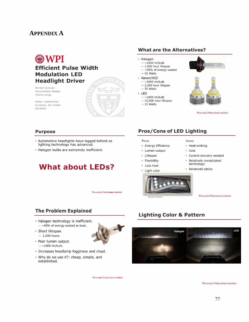
77
APPENDIX A

78

79

80

81
APPENDIX B