Triple-E - DNV's environmental & energy efficiency rating scheme for ships
Upload
maria-romina-angustiaCategory
view
23download
5
EFFICIENCY, RATING, AND APPLICATIONS OF
DYNAMOS
Camille Alexis J. RoxasMaria Janine B. LosabioJemar N. Palermo

APPLICATIONS OF DYNAMOS
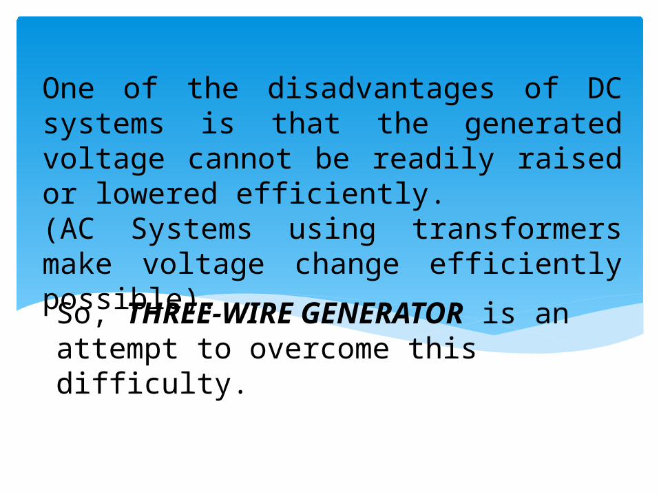
One of the disadvantages of DC systems is that the generated voltage cannot be readily raised or lowered efficiently.(AC Systems using transformers make voltage change efficiently possible).
So, THREE-WIRE GENERATOR is an attempt to overcome this difficulty.

What is a THREE-WIRE GENERATOR?• It is a generator that makes two
available voltages, one twice as much as the other.
Usually, this generator is designed for 230-V service, but it has provision for neutral, which serves to provide 115-V between it and either side of the line.
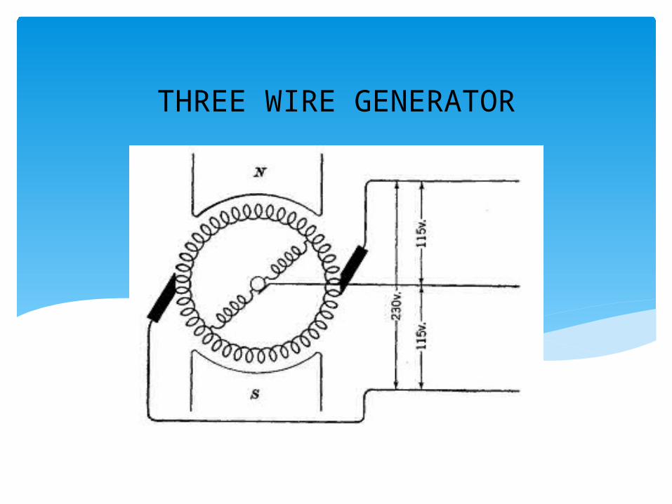
THREE WIRE GENERATOR

The use of the balancer set is to provide voltage balance on a three-wire system.
The balancer coil is simply a pair of reactor coils connecting points 180 electrical degrees apart on the armature winding and being themselves connected. The point at the reactor-coil connection is connected to the middle line of the three-wire system.
Inasmuch as any pair of reactor coils connects two points on the armature 180 electrical degrees apart, the voltage across a pair of coils is alternating.
The coils are wound on separate iron cores mounted on the armature, or are wound on separate cores outside the machine. With coils mounted on the armature, only one slip-ring is necessary; whereas, with separate cores outside the machine, two or more slip-rings are necessary.
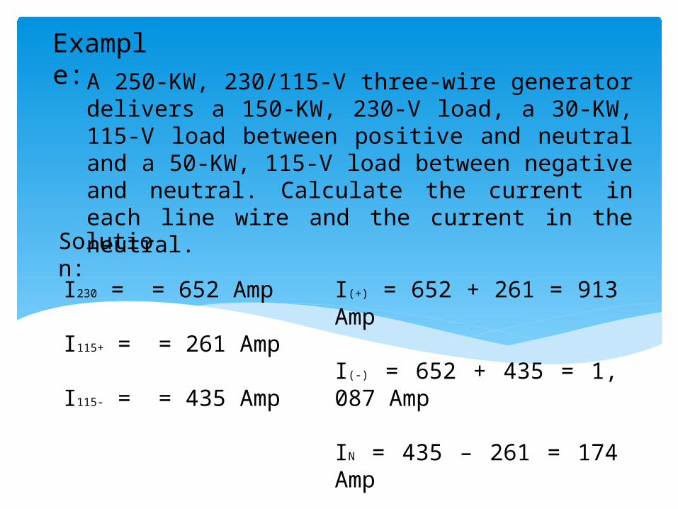
Example: A 250-KW, 230/115-V three-wire generator delivers a 150-
KW, 230-V load, a 30-KW, 115-V load between positive and neutral and a 50-KW, 115-V load between negative and neutral. Calculate the current in each line wire and the current in the neutral.
Solution:
I230 = = 652 Amp
I115+ = = 261 Amp
I115- = = 435 Amp
I(+) = 652 + 261 = 913 Amp
I(-) = 652 + 435 = 1, 087 Amp
IN = 435 – 261 = 174 Amp
Third Brush Generators• Often used on automobiles to provide
necessary electric power for the charging of the storage battery and the operation of lights.
• It is a special shunt generator with the field winding connected between the main brushes and the auxiliary, or the third brush.
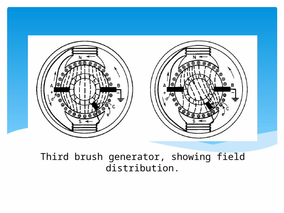
Third brush generator, showing field distribution.

As the speed of the automobile increased, thereby increasing the speed of the generator, the voltage tended to increase. This increase in the voltage increased the current delivered by the generator. But the increase in current so changed the magnetic flux distribution in the machine that the voltage between the third brush and main brush was reduced. This reduced the field current and therefore the flux of the machine and tended to bring the main voltage between the main and third brush back to its former value. This action did not maintain an absolutely constant voltage for different speeds, but the voltage was held within certain limits so that the extensive voltage which would overcharge the battery and shorten the life of the lamps was not developed at high speeds.

Diverter Pole Generator
• A special type of dc generators that have particular advantages for charging of batteries.
The machine is constructed with additional pole pieces ( the diverter poles) located midway between the main poles in the same manner as commutating poles. Each main pole is connected by a magnetic bridge to a one diverter pole. The winding of the main poles are connected in shunt with the armature winding, and the windings of the diverter poles is in series with the armature winding.

DIVERTER POLE GENERATOR

At no load, the diverter-pole current is zero, under which condition it produces no mmf; a good part of the main-pole flux is thus diverted through the magnetic shunts to the diverter poles. The flux is limited by the saturation of the bridges.Under load, however, the mmf of the diverter poles, prevents the main-pole flux from passing it to the diverter poles. Thus the diverted flux decreases as the load increases, the result being that the emf of the machine tends to be remain constant for all values of the load.By proper design of the bridge areas and their slots, it is possible to have a characteristic that is flat.