Efficiency of the Nam Theun 2 hydraulic structures on ...
24
Efficiency of the Nam Theun 2 hydraulic structures on water aeration and methane degassing Efficacité des structures hydrauliques de Nam Theun 2 sur l’aération de l’eau et le dégazage du méthane S. Descloux (1)* , V. Chanudet (1) , B. Taquet (1) , W. Rode (2) , P. Guédant (2) , D. Serça (3) , C. Deshmukh (3) , F. Guerin (4,5) (1) EDF, Hydro Engineering Centre, Sustainable Development Department, Savoie-Technolac, 73373 Le Bourget-du-Lac, France [email protected] (2) Nam Theun 2 Power Company Limited (NTPC), Environment & Social Division – Water Quality and Biodiversity Dept.– Gnommalath Office, PO Box 5862, Vientiane, Lao PDR (3) Laboratoire d’Aérologie, Observatoire Midi-Pyrénées, 14 Av. Édouard Belin, 31400 Toulouse, France (4) Université de Toulouse, UPS (OMP), LMTG, 14 Av. Édouard Belin, 31400 Toulouse, France (5) IRD, LMTG, 14 Av. Édouard Belin, 31400 Toulouse, France Abstract – Release of hypolimnetic water from man-made reservoirs can be a problem for downstream rivers. These effects can be significant mainly during the first years after the reservoir impoundment, especially in thermally stratified reservoirs favouring the release of anoxic methane-rich water. In tropical areas, higher temperatures decrease the oxygen solu- bility and enhance chemical processes responsible for the rise of reduced compounds. The Nam Theun 2 Reservoir was first filled in 2008. It experienced hypolimnetic deoxygenation and significant methane concentrations during the first 2 years. Dedicated structures to oxy- genate water and degas methane were designed during the study phase. The overall aerating and degassing effects of these hydraulics structures varied from very good to moderate. Results depend on the continuous water quality improvement with time as well as on the limi- ted range of upstream oxygen and methane concentrations tested. The hollow jet valve and the concrete tooth shaped structure were very efficient together with downstream natural tur- bulence in aerating/degassing compared to the staggered baffle blocks. Contrary to other structures, the efficiency of the baffle blocks structure is reduced with high discharges. The aeration weir showed a moderate efficiency in supplying oxygen to the water due to the high upstream oxygen saturations (close to 100%). However, it was very efficient for methane degassing even at low concentrations. Hydraulics structures of the Nam Theun 2 project are an efficient, reliable and low maintenance way to improve oxygen content and to degas methane. Key words – aeration, reservoir, sub-tropical, weir, degassing, oxygen, methane Hydroécol. Appl. © EDF, 2015 DOI: 10.1051/hydro/2015002 Article publié par EDP Sciences
Transcript of Efficiency of the Nam Theun 2 hydraulic structures on ...

Hydroécol. Appl.© EDF, 2015DOI: 10.1051/hydro/2015002
Efficiency of the Nam Theun 2 hydraulic structureson water aeration and methane degassing
Efficacité des structures hydrauliques de Nam Theun 2sur l’aération de l’eau et le dégazage du méthane
S. Descloux(1)*, V. Chanudet(1), B. Taquet(1), W. Rode(2), P. Guédant(2),
D. Serça(3), C. Deshmukh(3), F. Guerin(4,5)
(1) EDF, Hydro Engineering Centre, Sustainable Development Department, Savoie-Technolac, 73373 LeBourget-du-Lac, [email protected]
(2) Nam Theun 2 Power Company Limited (NTPC), Environment & Social Division – Water Quality andBiodiversity Dept.– Gnommalath Office, PO Box 5862, Vientiane, Lao PDR
(3) Laboratoire d’Aérologie, Observatoire Midi-Pyrénées, 14 Av. Édouard Belin, 31400 Toulouse, France(4) Université de Toulouse, UPS (OMP), LMTG, 14 Av. Édouard Belin, 31400 Toulouse, France(5) IRD, LMTG, 14 Av. Édouard Belin, 31400 Toulouse, France
Abstract – Release of hypolimnetic water from man-made reservoirs can be a problem fordownstream rivers. These effects can be significant mainly during the first years after thereservoir impoundment, especially in thermally stratified reservoirs favouring the release ofanoxic methane-rich water. In tropical areas, higher temperatures decrease the oxygen solu-bility and enhance chemical processes responsible for the rise of reduced compounds. TheNam Theun 2 Reservoir was first filled in 2008. It experienced hypolimnetic deoxygenationand significant methane concentrations during the first 2 years. Dedicated structures to oxy-genate water and degas methane were designed during the study phase. The overall aeratingand degassing effects of these hydraulics structures varied from very good to moderate.Results depend on the continuous water quality improvement with time as well as on the limi-ted range of upstream oxygen and methane concentrations tested. The hollow jet valve andthe concrete tooth shaped structure were very efficient together with downstream natural tur-bulence in aerating/degassing compared to the staggered baffle blocks. Contrary to otherstructures, the efficiency of the baffle blocks structure is reduced with high discharges. Theaeration weir showed a moderate efficiency in supplying oxygen to the water due to the highupstream oxygen saturations (close to 100%). However, it was very efficient for methanedegassing even at low concentrations. Hydraulics structures of the Nam Theun 2 project arean efficient, reliable and low maintenance way to improve oxygen content and to degasmethane.
Key words – aeration, reservoir, sub-tropical, weir, degassing, oxygen, methane
Article publié par EDP Sciences

2 S. Descloux et al.
Résumé – La délivrance d’eau provenant de l’hypolimnion des réservoirs artificiels peut êtreun problème pour la qualité de l’eau des rivières en aval. Ces effets peuvent être importantspendant les premières années après la mise en eau d’un réservoir et plus particulièrementdans les réservoirs stratifiés favorisant la délivrance d’une eau anoxique et riche en méthane.Dans les régions tropicales, les températures plus élevées diminuent la solubilité de l'oxy-gène et favorisent les processus chimiques responsables de l’augmentation des concentra-tions en composés réduits. Le réservoir de Nam Theun 2 a été mis en eau en 2008. Il aprésenté une désoxygénation de la couche hypolimnique et des concentrations significativesde méthane au cours des 2 premières années. Des structures dédiées à l’aération et au déga-zage du méthane ont été étudiées et mises en œuvre sur le site. L'efficacité globale de l’aéra-tion et du dégazage des différentes structures hydrauliques a été de très bonne à modérée.Les résultats sont évalués en tenant compte de l’amélioration continue de la qualité de l’eauet de la faible gamme de variation de concentrations d’oxygène dissous et de méthane dis-sous amont. La vanne à jet creux et la structure en forme de dent en béton ont été très effi-caces avec la turbulence naturelle aval pour l’aération et le dégazage comparativement auxblocs de dissipation. Contrairement à d'autres structures, l'efficacité de la structure en blocsde dissipation est réduite à fort débit. Le seuil aérateur a été modérément efficace pourl'apport d’oxygène compte tenu des hautes saturations amont (près de 100 %) mais il a ététrès efficace pour le dégazage du méthane, même à de faibles concentrations. Les structureshydrauliques du projet Nam Theun 2 s’avèrent efficaces pour aérer et dégazer le méthane.Elles sont fiables et nécessitent une faible maintenance.
Mots clés – aération, réservoir, sub-tropical, seuil, dégazage, oxygène, méthane
1 INTRODUCTION
Release of hypolimnetic water fromman-made reservoirs can alter thephysical and chemical quality of down-stream rivers, limit their uses and leadto a loss of biodiversity. These effectscan be significant during the first yearsafter impoundment or under strong res-ervoir stratification events and, aregenerally enhanced in tropical areaswhere higher temperatures decreasethe oxygen solubility and enhance thechemical processes of organic matterdegradation (Townsend, 1999; Abrilet al., 2005; Gregoire & Descloux,2009).
Newly impounded reservoirs causethe degradation of the flooded organicmatter that can lead to anoxia and high
concentration of reduced and dis-solved compounds. Among them, itcan be found ammonium (NH4
+), fer-rous iron (Fe2+), hydrogen sulfide(H2S), carbon dioxide (CO2) and meth-ane (CH4) (Galy-Lacaux et al., 1997,1999; Guérin et al., 2008). Concentra-tions are generally higher when thewater body is stratified (Abril et al.,2005). Under such conditions, hypolim-netic waters are isolated from the sur-face waters oxygenated from photo-synthesis and atmospheric gasexchange by the presence of a thermo-cline. Waters in hydroelectric reser-voirs are generally taken from the bot-tom layer, i.e. in the hypolimnion, tomaximise energy production (optimi-sation of the live volume). The releaseof bottom waters can thus affect

Efficiency of the Nam Theun 2 hydraulic structures on water aeration 3
downstream rivers throughout the yearor during specific seasons, for exampleduring the dry season when the rivercan be mostly influenced only by reser-voir releases. As rivers are generallyused for various purposes (drinkingwater, biodiversity, navigation andtourism, etc) and fulfill the function ofself-purification, it is of high importanceto preserve and guaranty their waterquality.
The minimum levels of (i) dissolvedoxygen (DO) to be maintained and (ii)reduced gas to be eliminated vary fromsite to site and with the physico-chemi-cal characteristics of the water, themorphology of the river and the dilutioneffect from downstream tributaries. Italso depends on the ecological require-ments of the aquatic community and onthe latitude (e.g. oxygen solubility isa function of water temperature). Thedownstream DO consumption by ben-thic community respiration or biologicaland chemical DO demand must also beconsidered. For instance, salmonidsswimming is altered below 2–5 mg.L-1
DO whereas tilapia and carps can swimat DO levels of 1–2 mg.L-1 (Kutty, 1972;Kutty & Saunders, 1973). Tropicalfishes generally have a higher toler-ance of low DO. Nevertheless, DO thatremains below 1 mg.L-1 (and corre-sponding DO saturations equivalent to~ 10% at 20 °C) for a few hours canaffect biodiversity and generally resultin large fish kills (Baylar et al., 2009).Studies of the direct effects of methaneon water organisms are very limited.Sackett and Brooks (1975) have shownthat under experimental conditions,hydrocarbons (methane and others)did not cause harmful effects on marinephytoplankton even at high dissolved
concentrations. Opposite results havebeen underlined with acute toxic gaseffects in marine fish starting at a con-centration of about 1 mg.L-1 (Patin,1999). But methane has the indirectdetrimental effect of reducing DO con-tent in oxic water bodies.
To maintain DO and gas concentra-tions compatible with aquatic life andother uses, many solutions have beentested to supply DO (namely aeration;Baylar et al., 2009). Solutions rangefrom hypolimnetic oxygen injection,reservoir clearing and selective with-drawal to the construction of dedicatedhydraulic structures like weirs or baffleblocks. Creation of turbulence byhydraulic structures and subsequentaeration is a principle utilized by aera-tion weirs and seems to be the mostefficient solution for aeration (Chanson,1995; EPRI, 2002; Emiroglu & Baylar,2003). DO transfer occurs when air isentrained into the flow in the form of alarge number of bubbles. These bub-bles greatly increase the surface areaavailable for mass transfer (Baylaret al., 2009). Very few man-made res-ervoirs are equipped for aeration withrespect to the total number of reser-voirs throughout the world. Structuresbuilt with the objective of degassingreduced gases are even more rare andthe current literature data are based onthe only case of the Petit Saut Reservoirin French Guiana (Gosse & Gregoire,1997; Gosse et al., 1997). Moreover,efficiency of other structures like hollowjet valves that are not specificallydesigned to increase DO concentrationor to degas have never been assessedon site.
The creation of the Nam Theun 2Reservoir (NT2) in the Lao PDR has led
4 S. Descloux et al.
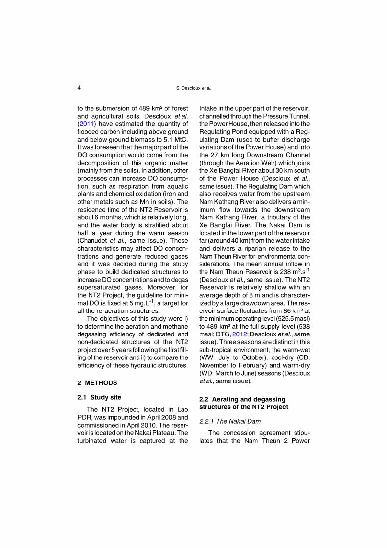
to the submersion of 489 km² of forestand agricultural soils. Descloux et al.(2011) have estimated the quantity offlooded carbon including above groundand below ground biomass to 5.1 MtC.It was foreseen that the major part of theDO consumption would come from thedecomposition of this organic matter(mainly from the soils). In addition, otherprocesses can increase DO consump-tion, such as respiration from aquaticplants and chemical oxidation (iron andother metals such as Mn in soils). Theresidence time of the NT2 Reservoir isabout 6 months, which is relatively long,and the water body is stratified abouthalf a year during the warm season(Chanudet et al., same issue). Thesecharacteristics may affect DO concen-trations and generate reduced gasesand it was decided during the studyphase to build dedicated structures toincreaseDOconcentrationsand todegassupersaturated gases. Moreover, forthe NT2 Project, the guideline for mini-mal DO is fixed at 5 mg.L-1, a target forall the re-aeration structures.
The objectives of this study were i)to determine the aeration and methanedegassing efficiency of dedicated andnon-dedicated structures of the NT2projectover5years following the first fill-ing of the reservoir and ii) to compare theefficiency of these hydraulic structures.
2 METHODS
2.1 Study site
The NT2 Project, located in LaoPDR, was impounded in April 2008 andcommissioned in April 2010. The reser-voir is located on the Nakai Plateau. Theturbinated water is captured at the
Intake in the upper part of the reservoir,channelled through the Pressure Tunnel,the Power House, then released into theRegulating Pond equipped with a Reg-ulating Dam (used to buffer dischargevariations of the Power House) and intothe 27 km long Downstream Channel(through the Aeration Weir) which joinsthe Xe Bangfai River about 30 km southof the Power House (Descloux et al.,same issue). The Regulating Dam whichalso receives water from the upstreamNam Kathang River also delivers a min-imum flow towards the downstreamNam Kathang River, a tributary of theXe Bangfai River. The Nakai Dam islocated in the lower part of the reservoirfar (around 40 km) from the water intakeand delivers a riparian release to theNam Theun River for environmental con-siderations. The mean annual inflow inthe Nam Theun Reservoir is 238 m3.s-1
(Descloux et al., same issue). The NT2Reservoir is relatively shallow with anaverage depth of 8 m and is character-ized by a large drawdown area. The res-ervoir surface fluctuates from 86 km² atthe minimum operating level (525.5 masl)to 489 km² at the full supply level (538masl; DTG, 2012; Descloux et al., sameissue). Three seasons are distinct in thissub-tropical environment; the warm-wet(WW: July to October), cool-dry (CD:November to February) and warm-dry(WD: March to June) seasons (Desclouxet al., same issue).
2.2 Aerating and degassingstructures of the NT2 Project
2.2.1 The Nakai Dam
The concession agreement stipu-lates that the Nam Theun 2 Power

Efficiency of the Nam Theun 2 hydraulic structures on water aeration 5
Company (NTPC) has to release aminimum environmental flow of 2 m3.s-1
into the downstream Nam Theun River.This flow is taken from the reservoirsurface, 2 meters below the surface,through a multi-level off-take structure(diameter 1.54 m). The flow then goesthrough a hollow jet valve (section of5 x 3.7 m) that creates turbulence oxy-genating the flow (Figs. 1 and 5A)which reaches a designed stilling basinbefore its release into the Nam TheunRiver. Air is also entrained into thebasin and it is the combined efficiencyof the two devices (jet and basin) andthe natural aeration along the 0.7 kmdownstream river stretch that wasassessed in this study. During highfloods, flow can be spilled out throughflap and radial gates.
2.2.2 The Regulating Dam
The Regulating Dam has three out-lets. The first structure is dedicated to
Fig. 1. Picture of the riparian release structure of thjet valve).
Fig. 1. Photographie du débit réservé relâché au s(vanne à jet creux).
the Downstream Channel water release(passing through point DCH1 in Fig. 5B).Based on the water level differencebetween the reservoir and the channel,around 40 MW of energy (which corre-sponds to approximately 315 m3.s-1)have to be dissipated downstream ofthe gates. A model was built to designadequate features with the objective ofdissipating this flow energy. A decisionwas made to dissipate this energy withstaggered baffle blocks installed in aconvergent section (7 blocks 3 m high,12 m width and 4 m long), made withhigh strength concrete (60 MPa), asshown in Figure 2. The high turbulencecreated by the energy dissipationdevices is deemed to produce a goodaeration of the water, for all the rangeof discharges.
The second outlet is through the‘restitution gate’ which releases flowshigher than 1 m3.s-1 dedicated to theNam Kathang River (Descloux et al.,same issue and point NKT3 in Fig. 5B).
e Nakai dam site on the Nam Theun River (hollow
ite du barrage de Nakai sur la rivière Nam Theun

6 S. Descloux et al.
It is capable to release the naturalupstream inflow plus 10 or 15 m3.s-1,depending on the power station opera-tion and natural inflows (from the upperNam Kathang) into the RegulatingPond. It has a capacity of 30 m3.s-1 atthe minimum operating level. In order toprovide a good aeration, a dedicatedconcrete tooth shaped device has beendesigned to split the flow jet in 2 parts,and spread it, in order to create a largearea of water in contact with air (Fig. 3).The third outlet is a single canal thatdelivers the minimum environmentalflow (below 1 m3.s-1) to the Nam Kathangduring the dry season. The dedicatedconcrete tooth shaped device is notused with this configuration.
2.2.3 The Aeration Weir
A weir was built approximately8.3 km downstream from the Regulating
Fig. 2. Picture of the staggered baffle blocks installegent section in the Downstream Channel.
Fig. 2. Photographie des blocs de dissipation instachenal aval.
Dam to aerate/degas the flow and thusimprove water quality in the Down-stream Channel before it flows into theXe Bangfai (Fig. 5C). It is a dedicatedstructure designed to provide maximumaeration at the maximum flow of330 m3.s-1. The structure includes a U-shaped weir made of reinforced con-crete walls. The total overflow crestlength is approximately 340 m. Sub-hor-izontal perforated wooden devices areattached to the total overflow crestlength (allow to spread the flow over1.2 m). They divide the flow over theweir into multiple discharges to increasethe water surface area as much as pos-sible to provide maximum aeration/degassing potential. The weir heightfrom crest to the downstream waterlevel is greater than 1.5 m at normal flow(330 m3.s-1), with a water mattressdepth almost equal to 3 m (Fig. 4). Thestructure performance was firstly tested
d downstream of the Regulating Dam in a conver-
llés en aval du barrage de démodulation dans le

Efficiency of the Nam Theun 2 hydraulic structures on water aeration 7
by a physical model study that focusedon bubble trajectories, and allowed thedesigners to implement deflection walls(vertical concrete wall attached to themain structure; Fig. 4). The water flow
Fig. 3. Picture of the concrete tooth shaped structuKathang River.
Fig. 3. Photographie des dents en béton installérivière Nam Kathang.
Fig. 4. Picture of the aerating weir downstream of t
Fig. 4. Photographie du seuil aérateur installé enaval.
speed in the Downstream Channel fromthe Regulated Dam to the Aerating Weirwas calculated to approximately 1.7 m.s-1
at 330 m3.s-1. The Downstream Channelis 56 m width (20 m horizontal and on
re downstream of the Regulating Dam in the Nam
es en aval du barrage de démodulation dans la
he regulating dam in the Downstream Channel.
aval du barrage de démodulation dans le chenal

8 S. Descloux et al.
each side: 2 x 3 m with a 3/1 slope and2 x 6 m with a 2/1 slope).
Other small weirs are situated allalong the Downstream Channel and areable to increase DO concentrations anddegas remaining reduced gases withlower efficiencies. Nevertheless, thereis no small weir between the RegulatingDam (DCH1) and the Aeration Weir(DCH2) and the Aeration Weir (DCH2)and the sampling station downstreamthe Aeration Weir (DCH3). The Tunneloutlet structure at the end of the Down-stream Channel is also dedicated todissipate the energy of the flow whilecreating high turbulences. These struc-tures are not included in the presentstudy as no water quality monitoringwas conducted there.
2.3 Physico-chemicalmeasurements
The physico-chemical water qualitycharacteristics have been monitored inthe NT2 system (hydroelectric reservoirand downstream rivers) since the firstfilling of the reservoir in April 2008. Theresults emphasize that the impound-ment of the reservoir induced a sub-stantial modification of the water qualityin the whole aquatic system which ispartially controlled by the hydrodynam-ics in the reservoir. During the WD andWW seasons, the reservoir water col-umn is thermally stratified with a warmoxic epilimnion and a cooler anoxichypolimnion (Chanudet et al., sameissue).
DO and methane (CH4) concentra-tions in water were measured weekly,fortnightly or monthly between April2008 and April 2013 at each monitoring
station (Descloux et al., same issue).The analytical methods, with the asso-ciated limits of detection and uncertain-ties (2% for DO saturation and 5% forCH4) are summarized in Deshmukhet al. (2014) and Chanudet et al. (sameissue). In the reservoir, between threeand six samples were taken (peristalticpump or sampling bottle) at each sam-pling point according to water columnand oxycline depths. In the rivers, onlysurface water was collected.
All the upstream/downstream meas-urements were done between 11 amand 2 pm within 2 hours (excepted forREG1/NKT3 where the measurementswere done within 24 hours due to fieldconstraints; this does not affect thequality of the analysis as the transfertime is greater than the lag time betweenthe two measurements). The upstreammeasurement has always been donebefore the downstream measurement.The oxygen values for 100% saturationat 20 °C, 25 °C and 30 °C are respec-tively 9.07, 8.24 and 7.54 mg.L-1.
2.4 Data analysis
2.4.1 The Nakai Dam
For aeration and degassing analysisat the dam site, upstream concentra-tions were calculated from measure-ments at RES1 (situated in the reservoiraround 700 m upstream of the dam) anddownstream concentrations were meas-uredabout 700 m from the release at theNTH3 station (Fig. 5A; Descloux et al.,same issue). At RES1, the thicknessand the depth of the water layer used forcalculation of the upstream concentrationdepend on the discharge and restitution

Efficiency of the Nam Theun 2 hydraulic structures on water aeration 9
A
CB
Fig. 5. Localisation of the sampling stations and length between stations and structures at A) theNakai Dam, B) the Regulating Pond and C) the Aerating Weir (© NTPC).
Fig. 5. Localisation des stations d’échantillonnage et distances entre les structures et les stations auA) barrage de Nakai, B) bassin de démodulation et C) seuil aérateur (© NTPC).

10 S. Descloux et al.
structure (riparian release, flap gates orradial gates). For low discharges (e.g.the riparian release; Q ≈ 2 m3.s-1),velocity measurements and simulations(Fabre et al., 2010) show that only theuppermost 3 meters are withdrawnthrough the multi-level off-take struc-ture used for the riparian release. Mostof the measurements (70% for DO and93% for CH4) were carried out with sucha low discharge. The depth and thick-ness of the water layer to consider forhigher discharges entering the multi-level off-take structure are more deli-cate to estimate. In this paper, only theflow passing through the intake surfacestructure and the hollow jet valve usedfor the riparian release are considered.DO measurements at RES1 (verticalresolution: surface level (0.2 m), thenevery 0.5 m in the uppermost 5 m andevery 1 m downwards) were directlyintegrated over the uppermost 3 metersto get an average DO value while CH4measurements were linearly interpo-lated to calculate the CH4 concentrationin the uppermost 3 meters (based onCH4 measurements made at the sur-face and 1 m above the oxycline usuallyfound between 5 and 10 m; Chanudetet al., same issue).
2.4.2 The Regulating Dam and the Aeration Weir
The aeration and degassing effi-ciencies of the Regulating Dam (into theDownstream Channel and in the NamKathang River; Fig. 5B) were analysedconsidering several discharges classes.Releases in the Nam Kathang using the‘restitution gate’ were divided into twodischarges classes: 1-5 m3.s-1 (26%,2.3 m3.s-1 in average) and > 5 m3.s-1
(29%, 17.0 m3.s-1 in average). Theremaining measurements (45%), donefor discharge < 1 m3.s-1, were not con-sidered as water was not releasedthrough the restitution gate: the dedi-cated concrete tooth shaped device isnot used with this configuration. For thetwo discharge classes, the flow is with-drawn through a sector gate openingfrom 9 to 11 m below the surface. Forthe two classes, upstream concentra-tions were calculated by integrating thewhole water column at REG1: meas-urements show that the physico-chem-ical parameters (DO or temperature forinstance) are almost constant over thewater column (Chanudet et al., sameissue). For instance, since the commis-sioning, the difference between surfaceand depth-averaged DO saturation didnot exceed 3% in average. This homo-geneity precluded any attempt to traceupstream water with physico-chemicalparameters such as conductivity forinstance to assess the exact waterthickness to consider. Therefore, thechoice of the water layer does not affectsignificantly the results and it justifiesthe use of a unique upstream concen-tration calculation method whatever thedischarge. Downstream concentrationswere measured at the surface at theNKT3 station (Fig. 5B; Descloux et al.,same issue).
Releases in the Downstream Chan-nel were also divided into three dis-charge classes: 0-100 m3.s-1 (24%,38.9 m3.s-1 in average for DO analysis),>100-200 m3.s-1 (16%, 147.1 m3.s-1 inaverage) and > 200 m3.s-1 (59%,280.3 m3.s-1 in average). For thesethree classes, upstream concentrationswerecalculatedby integrating thewholewater column at REG1, considering the
Efficiency of the Nam Theun 2 hydraulic structures on water aeration 11
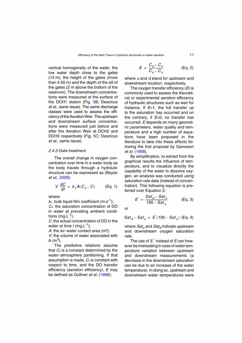
vertical homogeneity of the water, thelow water depth close to the gates(13 m), the height of the gates (morethan 4.50 m) and the depth of the sill ofthe gates (2 m above the bottom of thereservoir). The downstream concentra-tions were measured at the surface ofthe DCH1 station (Fig. 5B; Desclouxet al., same issue). The same dischargeclasses were used to assess the effi-ciencyof theAerationWeir.Theupstreamand downstream surface concentra-tions were measured just before andafter the Aeration Weir at DCH2 andDCH3 respectively (Fig. 5C; Desclouxet al., same issue).
2.4.3 Data treatment
The overall change in oxygen con-centration over time in a water body asthe body travels through a hydraulicstructure can be expressed as (Baylaret al., 2009):
(Eq. 1)
where:kL : bulk liquid film coefficient (m.s-1);Cs: the saturation concentration of DOin water at prevailing ambient condi-tions (mg.L-1);C: the actual concentration of DO in thewater at time t (mg.L-1);A: the air−water contact area (m²);V: the volume of water associated withA (m3).
The predictive relations assumethat Cs is a constant determined by thewater−atmosphere partitioning. If thatassumption is made, Cs is constant withrespect to time, and the DO transferefficiency (aeration efficiency), E maybe defined as Gulliver et al. (1998):
V dCdt-------- k LA Cs C–( )=
(Eq. 2)
where u and d stand for upstream anddownstream location, respectively.
The oxygen transfer efficiency (E) iscommonly used to assess the theoreti-cal or experimental aeration efficiencyof hydraulic structures such as weir forinstance. If E=1, the full transfer upto the saturation has occurred and onthe contrary, if E=0, no transfer hasoccurred. E depends on many geomet-ric parameters, water quality and tem-perature and a high number of equa-tions have been proposed in theliterature to take into these effects fol-lowing the first proposal by Gamesonet al. (1958).
By simplification, to extract from thegraphical results the influence of tem-perature, and to visualize directly thecapability of the water to dissolve oxy-gen, an analysis was conducted usingsaturation rate data (instead of concen-tration). This following equation is pre-ferred over Equation 2:
(Eq. 3)
or
(Eq. 4)
where Satu and Satd indicate upstreamand downstream oxygen saturationrate.
The use of instead of E can how-ever be misleading in case of water tem-perature variation between upstreamand downstream measurements (adecrease in the downstream saturationcan be due to an increase of the watertemperature). In doing so, upstream anddownstream water temperatures were
ECd Cu–
Cs Cu–---------------------=
E ′ Sat d Sat u–
100 Sat u–--------------------------------=
Sat d Sat u– E ′ 100 Sat u–( )=
E ′

12 S. Descloux et al.
recorded during each DO measure-ments. It appears that for each struc-ture, the differences between upstreamand downstream measurements werenegligible (see Chapter 3), for instancewater temperature differences betweenRES1 (uppermost 3 m) and NTH3,induced an average difference of 0.9%of saturation.
In the present study, the aerationefficiencies are measured in real condi-tions. The relevancy of a direct calcula-tion of from single upstream-down-stream couples may be jeopardized bymeasurement uncertainty or errors andnatural physical (tributary or groundwa-ter inputs) or bio-chemical processes(such as photosynthesis by phytoplank-ton and phytobenthos or DO consump-tion by biological respiration and chem-ical oxydation) that may occur betweenupstream and downstream measure-ments points (these effects can beenhanced with higher distance and timedelay between the two points). A globalvalue of was directly estimated fromEquation 4 for each hydraulic device byplotting Satd – Satu as a function of100 – Satu.
CH4 degassing efficiency (e) hasbeen defined as the ratio between theCH4 loss and the upstream concentra-tion (Abril et al., 2005):
· (Eq. 5)
This equation is acceptable for con-centrations of methane greater than theatmospheric saturation concentrationcorresponding to0.003µmol.L-1 at25 °C.
Slopes and intercepts of the regres-sion lines were tested using an ANCOVAand pair wise-comparisons to analyse
E ′
E ′
eCH4[ ]u CH4[ ]d–
CH4[ ]u------------------------------------------------=
the differences among regression equa-tions for each class of each structure.The overall significance level is 0.05.The R software was used (R Develop-ment Core Team, 2009).
3 RESULTS
3.1 The Nakai Dam
Aeration evolved with time andupstream DO saturation at the reservoirsite (Fig. 6). In 2008 and 2009, theupstream DO saturation level was low,ranging from 5.5% to 67.2% (23.0% inaverage, except during the 2009 WDseason ~55%) and the average aera-tion gain was about 60%. From the WD2010 season, the upstream saturationlevel increased (71.4% in averagebetween March 2010 and March 2013)and the aeration gain (downstream –upstream saturation) decreased.Above an upstream saturation of 80%,the capacity of the device to increasethe DO saturation level was low butallowed the downstream river to reachthe optimum of 100%. The CD seasonsalways showed a minimum upstreamsaturation level (Chanudet et al., sameissue) and concomitant higher aeration.The overall efficiency of the hollow jetvalve and the downstream stretch of theriver was high with = 0.91 close to theoptimum of 1 (Fig. 7).
The seasonal evolution of CH4 con-centrations at RES1 and NTH3 can befound in Deshmukh et al. (submitted).Upstream concentration ranged from0.03 to 65.9 µmol.L-1 while downstreamconcentration ranged from 0.07 to27.8 µmol.L-1. The overall efficiency of
E ′

Efficiency of the Nam Theun 2 hydraulic structures on water aeration 13
degassing by the hollow jet valve andthe downstream stretch was very goodand close to 100% even at very low con-centrations (e = 0.97; Fig. 8).
3.2 Regulating Dam
3.2.1 From the Regulating Dam to the Downstream Channel
The mean upstream DO saturationlevel at REG1 increased from 2009
Fig. 6. Evolution of the upstream (RES1) and dowture (°C) and discharges (m3.s-1; from Descloux etat the Nakai Dam site.
Fig. 6. Évolution de la saturation en oxygen (%),Descloux et al., même numéro) aux stations amonand 2013 au site du barrage de Nakai.
(46.9% in average) to 2012 (65.3%;Fig. 9). Contrary to RES1 (Fig. 6), themaximum upstream DO concentrationwas observed during the CD seasons.This phenomenon is due to the hydro-dynamic characteristics of the reservoir.At RES1, mixing of the water columndecreased DO concentration in the sub-surface layer due to mixing with DO-depleted bottom water, while mixingat the power station intake improvedDO concentration in the downstream
nstream (NTH3) oxygen saturation (%), tempera-al., same issue) with time between 2008 and 2013
de la température (°C) et du débit (m3.s-1 aprèst (RES1) et aval (NTH3) avec le temps entre 2008
14 S. Descloux et al.
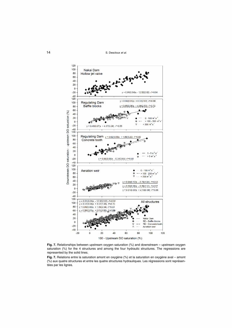
Fig. 7. Relationships between upstream oxygen saturation (%) and downstream – upstream oxygensaturation (%) for the 4 structures and among the four hydraulic structures. The regressions arerepresented by the solid lines.
Fig. 7. Relations entre la saturation amont en oxygène (%) et la saturation en oxygène aval – amont(%) aux quatre structures et entre les quatre structures hydrauliques. Les régressions sont représen-tées par les lignes.
Efficiency of the Nam Theun 2 hydraulic structures on water aeration 15
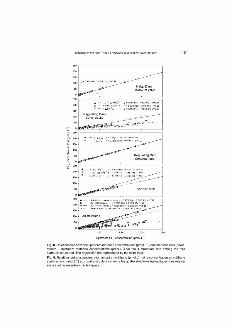
Fig. 8. Relationships between upstream methane concentrations (µmol.L-1) and methane loss (down-stream – upstream methane concentrations (µmol.L-1) for the 4 structures and among the fourhydraulic structures. The regression are represented by the solid lines.
Fig. 8. Relations entre la concentration amont en méthane (µmol.L-1) et la concentration en méthaneaval – amont (µmol.L-1) aux quatre structures et entre les quatre structures hydrauliques. Les régres-sions sont représentées par les lignes.
16 S. Descloux et al.
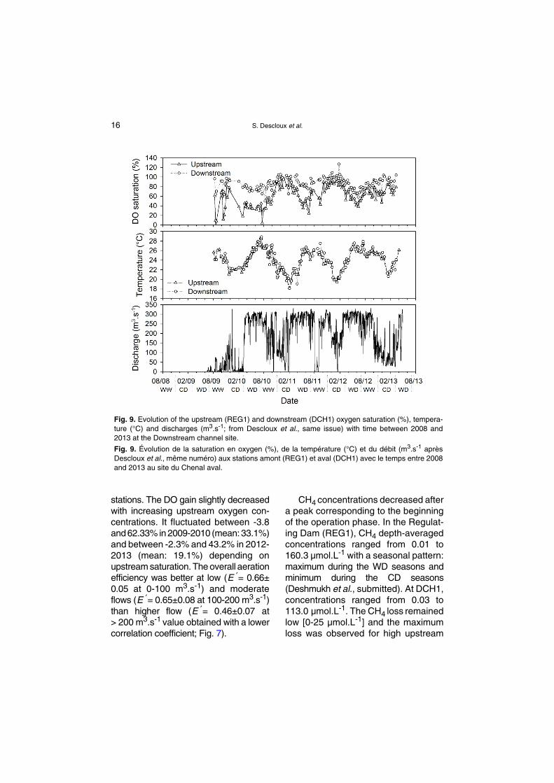
stations. The DO gain slightly decreasedwith increasing upstream oxygen con-centrations. It fluctuated between -3.8and 62.33% in 2009-2010 (mean: 33.1%)and between -2.3% and 43.2% in 2012-2013 (mean: 19.1%) depending onupstream saturation. The overall aerationefficiency was better at low ( = 0.66±0.05 at 0-100 m3.s-1) and moderateflows ( = 0.65±0.08 at 100-200 m3.s-1)than higher flow ( = 0.46±0.07 at> 200 m3.s-1 value obtained with a lowercorrelation coefficient; Fig. 7).
E ′
E ′
E ′
Fig. 9. Evolution of the upstream (REG1) and dowture (°C) and discharges (m3.s-1; from Descloux2013 at the Downstream channel site.
Fig. 9. Évolution de la saturation en oxygen (%),Descloux et al., même numéro) aux stations amonand 2013 au site du Chenal aval.
CH4 concentrations decreased aftera peak corresponding to the beginningof the operation phase. In the Regulat-ing Dam (REG1), CH4 depth-averagedconcentrations ranged from 0.01 to160.3 µmol.L-1 with a seasonal pattern:maximum during the WD seasons andminimum during the CD seasons(Deshmukh et al., submitted). At DCH1,concentrations ranged from 0.03 to113.0 µmol.L-1. The CH4 loss remainedlow [0-25 µmol.L-1] and the maximumloss was observed for high upstream
nstream (DCH1) oxygen saturation (%), tempera-et al., same issue) with time between 2008 and
de la température (°C) et du débit (m3.s-1 aprèst (REG1) et aval (DCH1) avec le temps entre 2008

Efficiency of the Nam Theun 2 hydraulic structures on water aeration 17
concentrations. Low and medium flowswere significantly more efficient in degas-sing (e = 0.62 and 0.69 respectively;Fig. 8) compared to higher flows(e = 0.29; P<0.001).
3.2.2 From the Regulating Dam to the Nam Kathang River
Upstream DO saturation levels arepresented in the previous section(Fig. 10). Downstream, intra-annual vari-ations were observed with maximum DOsaturation level during the CD seasons
Fig. 10. Evolution of the upstream (REG1) and dowture (°C) and discharges (m3.s-1; from Descloux etat the Nam Kathang site.
Fig. 10. Évolution de la saturation en oxygen (%),Descloux et al., même numéro) aux stations amonand 2013 au site de la Nam Kathang.
and minimum saturation level duringthe WD seasons (saturation gain at16.6% in the CD seasons and 46.5%during the WD seasons in average).Aeration efficiency did not differ amongthe two flow classes (P>0.05). The effi-ciency was high, ranging from 0.88 to0.92 (Fig. 7).
The upstream CH4 pattern isdescribed in the previous section. Forthe common upstream-downstreamdata set, maximum upstream concen-trations appeared in the WD season of2010 (155.3 µmol.L-1). Downstream,
nstream (NKT3) oxygen saturation (%), tempera-al., same issue) with time between 2008 and 2013
de la température (°C) et du débit (m3.s-1 aprèst REG1) et aval (NKT3) avec le temps entre 2008
18 S. Descloux et al.
from 2011, methane is almost absentfrom the water body during the WW(2.6 µmol.L-1) and CD (0.7 µmol.L-1)seasons in average (Deshmukh et al.,submitted). The degassing efficiencywas very high (e = 0.98; Fig. 8) with nosignificant differences among the twoflow classes.
3.3 Aeration Weir
DO saturation levels and CH4 con-centrations in the water at the weir sitewere highly influenced by the upstream
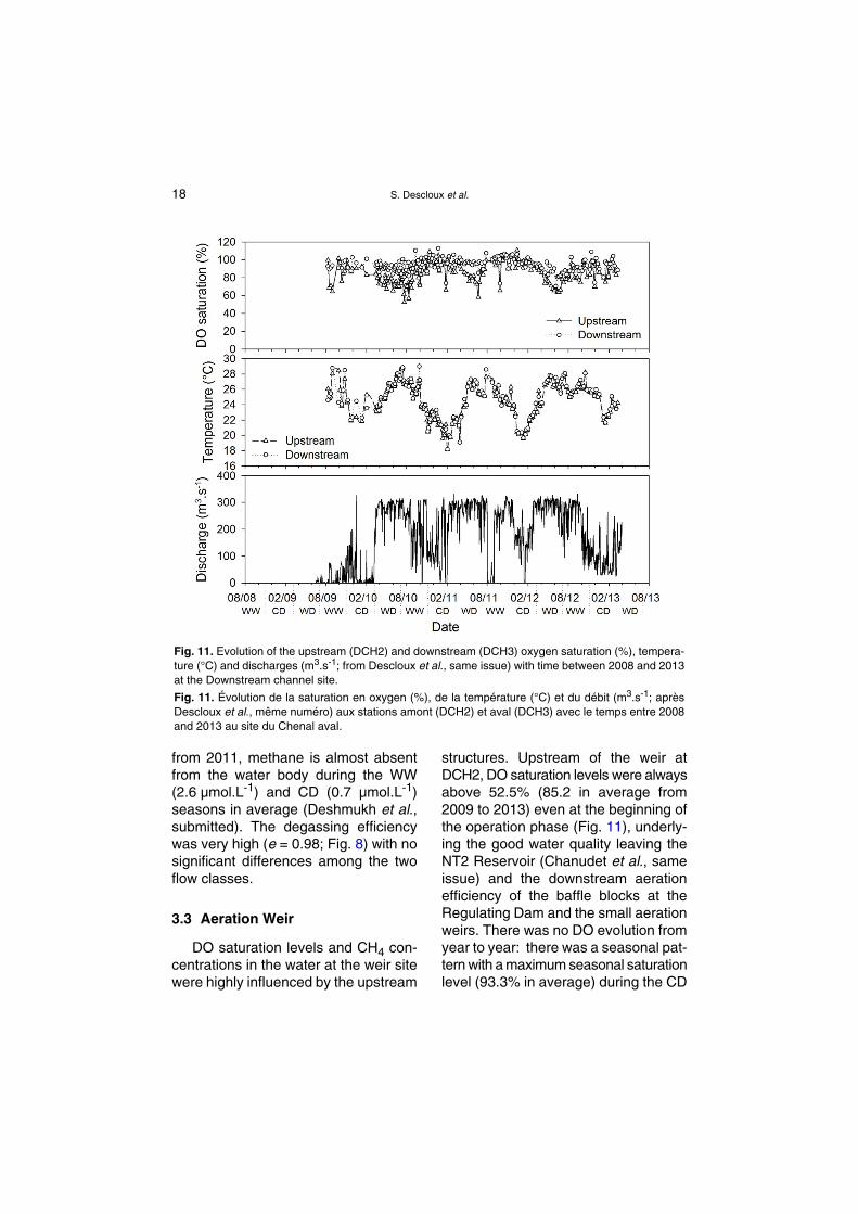
Fig. 11. Evolution of the upstream (DCH2) and dowture (°C) and discharges (m3.s-1; from Descloux etat the Downstream channel site.
Fig. 11. Évolution de la saturation en oxygen (%),Descloux et al., même numéro) aux stations amontand 2013 au site du Chenal aval.
structures. Upstream of the weir atDCH2, DO saturation levels were alwaysabove 52.5% (85.2 in average from2009 to 2013) even at the beginning ofthe operation phase (Fig. 11), underly-ing the good water quality leaving theNT2 Reservoir (Chanudet et al., sameissue) and the downstream aerationefficiency of the baffle blocks at theRegulating Dam and the small aerationweirs. There was no DO evolution fromyear to year: there was a seasonal pat-tern with a maximum seasonal saturationlevel (93.3% in average) during the CD
nstream (DCH3) oxygen saturation (%), tempera-al., same issue) with time between 2008 and 2013
de la température (°C) et du débit (m3.s-1; après(DCH2) et aval (DCH3) avec le temps entre 2008

Efficiency of the Nam Theun 2 hydraulic structures on water aeration 19
season and a minimum saturation level(78.4%) during the WD seasons. TheWW season presented intermediateDO saturation levels (83.7%). The meanDO apparent gain was therefore low(2.3% in average) during the CD seasonand at 13.3%during the WD season.The corresponding overall aeration effi-ciency seems moderate with a highereffect found at low flow ( = 0.64±0.12;Fig. 7) than medium and high flows( = 0.52±0.09 and 0.51±0.03 respec-tively; P<0.05).
The upstream CH4 concentrationsalso depended on the Regulating Damreleases and degassing efficiency. Theyfollowed the same inter and intra-annualpatterns as at REG1-DCH1 (Deshmukhet al., submitted). The mean upstreamCH4concentrations at this site decreasedsince the beginning of the operationphase from 31.74 µmol.L-1 in 2010 to7.16 µmol.L-1 in 2012 in average. Theupstream CH4 concentrations were stillhigh during the WD seasons but theCH4 loss was close to 100%. Since2011, during the WW and CD seasons,there was almost no more CH4 upstreamthe Aeration Weir (0.62 µmol.L-1 and1.89 µmol.L-1 for instance during the2012 WW and CD seasons). The over-all degassing efficiency was very highand significantly higher at low flow(e =1.00±0.01, Fig. 8) compared tomedium and high flows (e = 0.80±0.01and 0.79±0.01 respectively; P<0.001).The weir resulted in degassing ofalmost all of the remaining dissolvedCH4 in the Downstream Channel water.
3.4 Comparison of the structures
The data showed that all the devicesand the short downstream flow stretches
E ′
E ′
tested in this study were able to oxygen-ate waters. The hollow jet valve ofthe Nam Theun riparian release andthe concrete tooth shaped device ofthe Nam Kathang release had anaeration efficiency significantly higher( = 0.91±0.04 and 0.89±0.06 respec-tively; Fig. 7) than the staggered baffleblocks of the Downstream Channel( = 0.57±0.04; P<0.001) and the down-stream Aeration Weir ( = 0.56±0.03;P<0.001). The downstream AerationWeir that has been designed to aeratethe water seems the less efficient struc-ture, but the uncertainty is high asupstream measurements are close sat-uration. Efficiencies of the staggered baf-fle blocks and downstream Aeration Weirwere not significantly different (P>0.05).
The hollow jet valve of the riparianrelease and the concrete tooth shapeddevice of the Nam Kathang releasewere able to degas CH4 efficiently(e = 0.97±0.01 and 0.98±0.002 respec-tively, Fig. 8). Their efficiencies weresignificantly higher than the AerationWeir that remained quite efficient(e = 0.79±0.01; P<0.001; Fig. 7) andthan the staggered baffle blocks of theDownstream Channel which had a lowefficiency at high flow (e = 0.29±0.01;P<0.001). It has to be noted that theAeration Weir was very efficient at lowflow (e = 1±0.01, Fig. 8).
4 DISCUSSION
The aeration and methane degas-sing efficiencies depend on the type ofhydraulic structures through which theflow passes but also on other parame-ters like the magnitude of the discharge,the water temperature, the length of
E ′
E ′
E ′

20 S. Descloux et al.
time of the air-water exchange (Chanson,1995; EPRI, 2002; Emiroglu & Baylar,2006). Moreover, to obtain an unbiasedestimate of the intrinsic efficiency of thedevices, an assessment of the contribu-tion of flow stretches between thedevices and the downstream measure-ment points should have been madeand it would have been better to test thestructure under the entire range ofupstream conditions (0 to 100% ofupstream DO saturations and low tovery high CH4 saturations); which hasnot been possible to test for the AerationWeir for instance. Upstream DO satu-rations were too close to the saturationat this site preventing any measure-ment at low DO saturation conditionsand thus, it may have artificially under-estimate the intrinsic efficiency poten-tial of the structure (see also Chapter 2.3on uncertainties and calculations).
Our study demonstrates that, for therange of upstream DO and methaneconcentrations tested, aeration effi-ciency is very high with the hydraulicsystems using the hollow jet valve andthe concrete tooth, substantial with thedownstream weir and moderately effi-cient using the baffle blocks especiallyat high discharges. Deswal (2009)found in a laboratory experiment thatDO aeration efficiency of a hollow jetvalve increases with the increase in jetvelocity and that this device is compet-itive with other types of aeration sys-tems. At NT2, the hollow jet after pass-ing through the atmosphere plungesinto a water pool where substantialamount of air is entrained, leading to ahigh air-water interfacial area. At NT2,water flow was constant and the overallgood aeration efficiency was confirmedon site.
The three devices that were testedunder contrasting water flows generallypresented a better aeration efficienciesat low flows. This result is consistentwith previous studies (Chanson, 1995;Richard et al., 2005) that demonstratedthat low flows had higher waterfall, facil-itating the flow to plunge into the waterbody. At low discharges, breakup of thejet is observed as drop height increases.High flows decrease the total height ofthe Aeration Weir and thus both theduration of the air-water exchange andthe depth of air bubbles driven into thewater. The efficiency of a weir wasfound to be maximum at a tailwaterdepth of approximate 0.6 times the dropheight, indicating that a trade-off existsbetween bubble residence time, pres-sure, and turbulence levels (Avery &Novak, 1978). High flows may alsodecrease the turbulences created bythe structure (baffle blocks or concretetooth) by decreasing the difference ofwater level between the upstream andthe downstream of the structure. At theNam Kathang site, contrary to the otherdevices, the maximum flow recordedduring the measurements remained low(41 m3.s-1) thus limiting the effect ondownstream water level. The weirremained moderately efficient for oxy-genation but is less sensitive to thewater discharge due to its optimizedconception. The aerating weir locateddownstream of the Petit Saut Reservoir(French Guiana) had an overall aerat-ing efficiency close to 0.90 for tur-binated discharge up to 200 m3.s–1
(Gosse & Gregoire, 1997; Richard et al.,2005). The high level of efficiency athigh discharge is coming from thedesign of the weir made of hexagonalmetallic structures with two consecutive
Efficiency of the Nam Theun 2 hydraulic structures on water aeration 21
falls. Other studies from Hauser &Proctor (1993), reported an efficiencyof the aerating single fall weirs of SouthHolston and Chatuge around 0.60 and0.68 respectively and Baylar & Bagatur(2000) reported an efficiency of approx-imately 0.70 for low-head overflowweirs. All of these aeration efficiencystudies are in accordance with theresults of our study.
Our hypothesis suggesting that baf-fle blocks are able to highly aerate thewater body was based on the study ofKaya & Emiroglu (2010), that havereported that storm water systems, chan-nels and canals commonly use baffleblocks or baffled chutes for energy dis-sipation. They indicated a close rela-tionship between energy dissipationand oxygen transfer efficiency and haveshown an effective oxygen transfer.Johnson (1975), also previously pre-dicted that flow into a highly baffledbasin might produce higher aeration thana conventional hydraulic jump basin.This is not supported by the results ofthe monitoring, with the baffle blockstructure being only moderately effi-cient. Contrary to the hollow jet valve,the baffle blocks (and the concretetooth) were not designed to have aplunging flow increasing the air-waterexchange, which could partially explainthe results. The overall efficiency of thebaffle blocks can be compared to aera-tion efficiency of natural stepped cas-cades. Toombes & Chanson (2000)reviewed the efficiency of stepped cas-cades mainly located in the USA andEmiroglu & Baylar (2006) measuredaeration efficiency of stepped chutes inan experiment. They found aerationefficiencies close to our study rangingfrom 0.50 to 1.00 depending of the flow
and the height of the steps. The higherthe step is, the better the efficiency is.Overall stepped cascades were veryefficient because of the strong turbu-lence mixing and associated air entrain-ment and residence time. They alsofound that aeration efficiency was betterat low flow (nappe flow regime).
The hollow jet valve, the concretetooth structure and the Aerating Weirdemonstrated a very good efficiency indegassing CH4. The baffle blocks struc-ture is moderately efficient in oxygenat-ing and degassing at low and interme-diate flow discharge and is not efficientat high flow discharge. Nevertheless,flow discharge seems to have lesseffect on CH4 degassing efficiency thanfor aeration for other structures. Forinstance the CH4 degassing efficiencyof the concrete tooth structure is equiv-alent whatever the flow discharge.
Dissolved CH4 concentrationsremained high at DCH2 (upstream ofthe Aeration Weir) and the AerationWeir contributed to the elimination ofalmost all of the remaining CH4 from thewater body. The weir installed in March1995 in the Petit Saut Reservoir, had agood degassing efficiency similar to theNT2 Aeration Weir, with close to 80% ofthe dissolved CH4 eliminated from theturbined water (Richard et al., 2005;Gregoire & Descloux, 2009).
Except for the baffle blocks structureat high flow discharge, all the hydraulicstructures of the NT2 Project are able toaerate/degas the water body with agood efficiency. These structures havethe advantages to be reliable whilerequiring low maintenance. The hollowjet valve and the concrete tooth struc-ture are very efficient in aerating/degas-sing waters but they can be used only

22 S. Descloux et al.
for low flows contrary to other structuresthat can be used under a wide range offlow discharge.
Thanks to the hydraulic structures,no anoxia/low DO saturations wereobserved since the beginning of themonitoring into the downstream rivers(Chanudet et al., same issue). The spe-cific design and level of the waterintakes also contribute to improve thewaterqualityof thedownstreamreleases.For instance the Nam Theun Rivermainly received water from the sub-sur-face of the reservoir whereas the Down-stream Channel and Nam KathangRiver receive mixed water from the NT2Reservoir through the Regulating Pond(Chanudet et al., same issue).
5 CONCLUSION
The NT2 Reservoir was firstimpounded in 2008. The reservoir expe-rienced hypolimnetic deoxygenationand periods of anoxia below the ther-mocline during the first 2 years that wereanticipated with dedicated aerating civilwork structures. The study assessed forthe first time the efficiency, on site, ofseveral dedicated and non-dedicatedstructures on aeration and CH4 degas-sing. Moreover, the time series allowsfor a quantification of the evolution ofthese effects with time, taking intoaccount that some civil works weretested for a limited range of upstreamDO and methane concentrations. Withthe improvement of the water quality(increase in DO saturation and decreaseof CH4 contents), the overall aeratingand degassing effects of the hydraulicsstructure ranged from very good to mod-erate. The hollow jet valve and the con-crete tooth shaped structure were more
efficient in aerating/degassing com-pared to the staggered baffle blocks. Atthe Aeration Weir the DO gain is limitedby the high upstream saturation but thisdevice is very efficient for methanedegassing, even at low concentrations.While the DO content could have beengood in the Downstream Channel with-out the Aeration Weir, it was obviouslyuseful to eliminate the remaining meth-ane in water. The water quality of thedownstream rivers of the NT2 Projecthas always been good since theimpoundment of the reservoir thanks tothe particulate design of the Intake, theoverall water quality of the reservoir andthe aeration of the hydraulic structuresexamined in this study.
These hydraulics structures are anefficient, reliable and low maintenanceway to improve DO and to degas CH4at reservoir releases. However the effi-ciency of a structure is always a trade-off between the energy production lossdue to the head reduction and the down-stream water quality requirements.
ACKNOWLEDGMENTS
This research was conducted at theAquatic Environment Laboratory of NamTheun 2 Power Company in Lao PDRwhose Shareholders are Électricité deFrance, Lao Holding State Enterpriseand Electricity Generating Public Com-pany Limited of Thailand.
The authors would like to thank theNam Theun 2 Power Company (NTPC)for providing the logistic support on siterelated to field activities and the Tech-nical Division of NTPC, for providingkey technical drawings. We are alsograteful to the team of the Aquatic Envi-ronment Laboratory (AEL) for chemistry

Efficiency of the Nam Theun 2 hydraulic structures on water aeration 23
analyses and their help during fieldtrips. Finally, we are thankful to LeahBêche, who reviewed and improvedthis version of the manuscript as anative English-speaker.
REFERENCES
Abril G., Guérin F., Richard S., Delmas R.,Galy-Lacaux C., Gosse P., Tremblay A.,Varfalvy L., dos Santos M.A. & MatvienkoB., 2005. Carbon dioxide and methaneemissions and the carbon budget of a10-year old tropical reservoir (Petit Saut,French Guiana). Glob. Biogeochem.Cycles 19(4) : 16 p.
Avery S.T. & Novak P., 1978. Oxygen Trans-fer at Hydraulic Structures. J. Hyd. Div.,ASCE 104 : 1521-1540.
Baylar A. & Bagatur T., 2000. Study of Aera-tion Efficiency at Weirs. Turk J. Engin.Environ. Sci. 24 : 255-264.
Baylar A., Kisi O. & Emiroglu M.E., 2009.Modeling Air Entrainment Rate andAeration Efficiency of Weirs Using ANNApproach. G.U. J. Sci. 22(2) : 107-116.
Chanudet V., Guédant P., Rode W., GodonA., Guérin F., Serça D., Deshmukh C. &Descloux S., 2015. Evolution of the phy-sico-chemical water quality in the NamTheun 2 Reservoir and downstreamrivers for the first 5 years after impound-ment. Hydroécol. Appl. (same issue).
Chanson H. 1995. Predicting OxygenContent Downstream of Weirs, Spil-lways and Waterways. Proc. Instn Civ.Engrs Wat. Marit. & Energy, UK, Vol.112, Mar., pp. 20-30 (ISSN 0965-0946).
Descloux S., Chanudet V., Poilvé H. &Grégoire A., 2011. Coassesment of bio-mass and soil organic carbon stocks in afuture reservoir located in Southern Asia.Environ. Monit. Assess. 173 : 723-741.
Descloux S., Guedant P., Phommachanh D.& Luthi R., 2015. Main features of the
Nam Theun 2 hydroelectric project (LaoPDR) and the associated environmentalmonitoring programme. Hydroécol. Appl.(same issue).
Deshmukh C., Serça D., Delon C., Tardif R.,Demarty M., Jarnot C., Meyerfeld Y.,Chanudet V., Guédant P., Rode W.,Descloux S. & Guérin F. (2014). Physicalcontrols on CH 4 emissions from a newlyflooded subtropical freshwater hydroe-lectric reservoir: Nam Theun 2. Biogeos-ciences Discussions 11(2), 3271-3317.
Deshmukh C., Guérin F., Pighini S.,Vongkhamsao A., Guédant P., Rode W.,Chanudet V., Descloux S., Godon A. &Serça D. Low methane (CH4) emissionsdownstream a newly flooded subtropicalhydroelectric reservoir in southeastAsia: the Nam Theun 2 Reservoir (LaoPDR). Biogeosciences, submitted.
Deswal S., 2009. Oxygenation by hollowplungingwater jet.J.Instit.Engin.7:40-47.
DTG, 2012. Rapport : Nakai Reservoir onthe Nam Theun River, capacity curvecalculation, 2012 data, Grenoble, 9 p.
Emiroglu M.E. & Baylar A., 2003. Experimen-tal Study of the Influence of Different WeirTypes on the Rate of Air Entrainment.Water Qual. Res. J. Canada 38 : 769-783.
Emiroglu M.E. & Baylar A., 2006. Self-aera-tion in smooth and stepped chutes. Int. J.Sci.Technol. 1(2) : 105-113.
EPRI (Electric Power Research Institute),2002. Maintaining and Monitoring Dis-solved Oxygen at Hydroelectric Pro-jects: Status Report, EPRI Palo Alto, CA:2002 1005194, 194 p.
Fabre V., Chanudet V. & Bellet L., 2010.Results of the velocity measurements onthe Nam Theun 2 reservoir, EDF reportIH.NT-WQ.ENV.00041A, 25 p.
Galy-Lacaux C., Delmas R., Jambert C.,Dumestre J.F., Labroue L., Richard S. &GosseP.,1997.Gaseousemissionsandoxygen consumption in hydroelectricdams: A case study in French Guyana.Glob. Biogeochem. Cycles 11 : 471-483.

24 S. Descloux et al.
Galy-Lacaux C., Delmas R., Kouadio G.,Richard S. & Gosse P., 1999. Long-termgreenhouse gas emissions from hydroe-lectric reservoirs in tropical forest regions.Glob. Biogeochem. Cycles 13 : 503-517.
Gameson A., Vandyke K. & Ogden C., 1958.The effect of temperature on aeration atweirs. Water Engineering 62.
Gosse P. & Gregoire A., 1997. Dispositif deréoxygénation artificielle du Sinnamaryà l’aval du barrage de Petit-Saut(Guyane). Hydroécol. Appl. 9 : 23-56.
Gosse P., Sabaton S., Travade F. & Eon J.,1997. EDF experience in improving reser-voir releases for ecological purposes.Water for a changing global community.Energy and Water: Sustainable Develop-ment. In: HollyM.&AlsaffarA. (Eds.),452-458, Am. Soc. Civ. Eng., New-York, 1997.
Gregoire A. & Descloux S., 2009. Advan-tages and disadvantages of an aeratingweir in a tropical zone. Verh. Internat.Verein. Limnol. 30 : 850-853.
Guérin F., Abril G., de Junet A., & BonnetM.-P.,2008.Anaerobicdecompositionoftropical soils and plant material: Implica-tion for the CO2 and CH4 budget of thePetit Saut Reservoir. Appl. Geochem.23 : 2272-2283.
Gulliver J.S., Wilhelms S.C. & Parkhill K.L.,1998. Predictive capabilities in oxygentransfer at hydraulic structures. J.hydraulic Engin. 124(7) : 664-671.
Hauser G. & Proctor G., 1993. Performanceof prototype aerating weirs downstreamfrom TVA Hydropower dams. Proc. Natl.Conf. Hydraul. Eng. San Francisco.ASCE, p. 99.
Johnson P.L., 1975. Prediction of DissolvedGas at Hydraulic Structures. Enginee-ring and Research Center Bureau ofReclamation Denver, Colorado 80225,Report GR-8-75, 78 p.
Kaya N. & Emiroglu M.E., 2010. Study ofoxygen transfer efficiency at baffled
chutes. Proceedings of the ICE - WaterManagement, Vol. 163, Issue 9, July2010, pp. 447-456.
Kutty M.N., 1972. Respiratory quotient andammonia excretion in Tilapia mossam-bica. Marine Biology 16(2) : 126-133.
Kutty M.N., & Saunders R.L., 1973. Swim-ming performance of young Atlantic sal-mon (Salmo salar) as affected byreduced ambient oxygen concentration.Journal of the Fisheries Board ofCanada 30(2) : 223-227.
Patin S., 1999. Environmental impact of theoffshore oil and gas industry. Economi-tor Publication 448.
R Development Core Team, 2009. A lan-guage and environment for statisticalcomputing. R Foundation for statisticalcomputing, Vienna, Austria.
Richard S., Gregoire A. & Gosse P., 2005.The efficiency of an artificial weir in oxy-genating and removing CH4 from waterreleased by the Petit Saut hydroelectricdam (French Guiana). Revue desSciences de l’Eau 18 : 127-141.
SackettW.M.&BrooksJ.M.,1975.Originanddistributions of low molecular weighthydrocarbons in Gulf of Mexico coastalwaters. In: Church T.M. (Ed.), MarineChemistry in the Coastal Environment,Am. Chem. Soc. Symp. Ser., 18, pp. 211-230.
Toombes L. & Chanson H., 2000. Air-waterflow and gas transfer at aeration cas-cades: A comparative study of smoothand stepped chutes. Hydraulics of Step-ped Spillways, In: Minor and Hager(Eds.), 2000, Balkema, Rotterdam, ISBN905809 135X.
Townsend S.A., 1999. The seasonal patternof dissolved oxygen, and hypolimneticdeoxygenation, in two tropical Australianreservoirs. Lakes & Reservoirs: Research& Management 4 : 41-53.