effects of various thicknesses on load to fracture of posterior cad ...
70
EFFECTS OF VARIOUS THICKNESSES ON LOAD TO FRACTURE OF POSTERIOR CAD/CAM LITHIUM DISILICATE GLASS CERAMIC CROWNS SUBJECTED TO CYCLIC FATIGUE by Nadia Al-Angari Submitted to the Graduate Faculty of the School of Dentistry in partial fulfillment of the requirements for the degree of Master of Science in Dentistry, Indiana University School of Dentistry, 2015.
Transcript of effects of various thicknesses on load to fracture of posterior cad ...

EFFECTS OF VARIOUS THICKNESSES ON LOAD TO FRACTURE OF
POSTERIOR CAD/CAM LITHIUM DISILICATE GLASS
CERAMIC CROWNS SUBJECTED TO
CYCLIC FATIGUE
by
Nadia Al-Angari
Submitted to the Graduate Faculty of the School of
Dentistry in partial fulfillment of the requirements
for the degree of Master of Science in Dentistry,
Indiana University School of Dentistry, 2015.

ii
Thesis accepted by the faculty of the Department of Prosthodontics, Indiana
University School of Dentistry, in partial fulfillment of the requirements for the degree of
Master of Science in Dentistry.
David T. Brown
Steven P. Haug
Marco C. Botino
Jeffrey A. Platt
Chair of the Research Committee
John A. Levon
Program Director
Date

iii
DEDICATION

iv
This thesis is dedicated to my beloved family, my husband, Dr. Yasir Alsenaidi,
my children, Ibrahim and Sultan, and my parents, Dr. Sultan Alangari and Khairiah
Alqahtani.

v
ACKNOWLEDGMENTS

vi
I would like to express my sincere gratitude to my mentor, Dr. Jeffrey Platt, for all
his help and guidance throughout this research study. His efforts and dedication made the
completion of this research possible.
Also, I would like to thank my committee members, Drs. David T. Brown, Steven
P. Haug, Marco C. Bottino, and John A. Levon for their valuable suggestions and review.
Special thanks go to Dr. Ghaeth Yassen for his help and assistance, and to Mr.
George Eckert for his statistical expertise, which helped in completing my experiment.
Finally, I would like to thank my family for their support and encouragement
during my residency and study.

vii
TABLE OF CONTENTS

viii
Introduction………………………………………………………………………………..1
Review of Literature ........................................................................................................... 6
Materials and Methods ...................................................................................................... 13
Results ............................................................................................................................... 20
Tables and Figures ............................................................................................................ 22
Discussion ......................................................................................................................... 44
Summary and Conclusion ................................................................................................. 50
References ......................................................................................................................... 52
Abstract ............................................................................................................................. 55
Curriculum Vitae

ix
LIST OF ILLUSTRATIONS

x
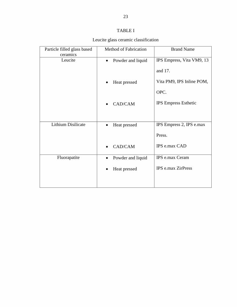
TABLE I Leucite glass ceramic classification…………………………. 23
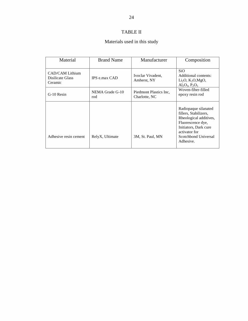
TABLE II Materials used in this study…………………………………. 24
TABLE III Description of experimental groups…………………………. 25
TABLE IV Means of Load-to-Fracture (N) for various thicknesses of
CAD/CAM lithium disilicate glass- ceramic crowns subjected
to cyclic fatigue………………………………………………
26
FIGURE 1 Sample design using baseplate wax to fabricate specimen for
testing………………………………………………………..
27
FIGURE 2 Dupication of the wax pattern using dental silicone to
fabricate a mold………………………………………………
28
FIGURE 3 Epoxy resin die material kit as provided from the
manufacturer………………………………………………….
29
FIGURE 4 Crown design using software for CAD/CAM machine……… 30
FIGURE 5 CAD/CAM all ceramic crown after milling and separated
with a disc prior to glazing in the oven………………………
31
FIGURE 6 Surface treatment of all ceramic crown using HF acid etching
and silane coupling agent……………………………………
32
FIGURE 7 CAD/CAM all ceramic crown after cementation on the epoxy
resin die………………………………………………………
33
FIGURE 8 Four different thicknesses of lithium disilicate glass ceramic.. 34
FIGURE 9 Instron testing machine………………………………………. 35
FIGURE 10 Close up view of the position of the loading tip in relation to
the crown anatomy……………………………………………
36
FIGURE 11 Instron testing machine monitor showing the cyclic load…… 37
FIGURE 12 G10 tip………………………………………………………. 38
FIGURE 13 G10 tips……………………………………………………… 39
FIGURE 14 Metal loading tip for static loading…………………………… 40

xi
FIGURE 15 Failure of 2.0-mm ceramic crown after static loading……….. 41
FIGURE 16 Failure of 1.5-mm ceramic crown after static loading……….. 42
FIGURE 17 Mean load to fracture (N)…………………………………….. 43

1
INTRODUCTION

2
Patients’ awareness of new esthetic treatment modalities, such as all-ceramic
restorations, challenges the dentist to use new technologies to meet patient desires.
Single visit treatment for CAD/CAM all ceramic crowns versus multiple appointments
for pressed ceramics, in terms of impression making, wax up and laboratory work, is one
of the preferences of patients in the dental clinic. Their goal is to achieve dental
restorative treatment in a short time. Throughout the years, introduction of new materials
and techniques has occurred rapidly, and research to test those materials has increased in
an attempt to shift towards evidence- based dentistry (Kelly et al, 1989).1
High leucite-containing ceramic and optimal pressable glasses were introduced in
the late 1980’s as the first pressable ceramic materials (Table I). A glass ceramic based
on a SiO2–Li2O system was developed in 2004 (Empress II, Ivoclar-Vivadent®
).
Crystalline filler particles were added to increase the strength, thermal expansion and
contraction behavior of ceramics. Other types of filler additions include particles of high-
melting glasses that are stable at the firing temperature of the ceramic. The crystalline
phase that forms is a lithium disilicate (Li2Si2O5) and makes up about 70% of the volume
of the glass ceramic. Lithium disilicate has an unusual microstructure that consists of
randomly oriented small interlocking plate-like crystals. This may improve the material
strength since the needle-like crystals may deflect, branch or blunt the cracks. Arrested
crack propagation through the material provides a substantial increase in the flexural
strength. Despite the increase in strength of the leucite-reinforced pressed material,
fracture is still possible when used in the posterior region.2

3
Lithium disilicate re-emerged in 2006 as a partially crystallized milling block.
The flexural strength of the material was found to be more than 170 percent than any
currently used leucite-reinforced ceramics. The use of CAD/CAM milling for different
restorative treatments such as zirconium dioxide or metal frameworks for full-contoured
crowns (lithium disilicate at chairside or in the laboratory) or implant abutments opened
the market for digitized restorative dentistry.
The surface damage produced by the CAD/CAM milling procedure significantly
reduced the strength of zirconia which could be further weakened by different surface
treatment methods resulting in unexpected failures at stresses much lower than the ideal
strength of the material.3
A seven year survival rate of 94.6 percent has been reported for CAD/CAM-
generated esthetic ceramic molar crowns adhesively cemented to natural tooth
preparations. Data on fatigue strength of CAD/CAM-generated esthetic posterior
ceramics is lacking.4 It appears that various stages of conventionally fabricated crowns
(impression making, master cast fabrication, waxing, investing, casting, veneer addition,
and finishing) may contribute to distortion of the prosthesis. Therefore, eliminating all
those variables in a CAD/CAM system should minimize the variability and improve the
final outcome of a prosthesis.1
As restorative materials, dental ceramics have disadvantages mostly due to their
inability to withstand functional forces that are present in the oral cavity. Therefore, they
have limited application in the molar areas.4,5
Further development in these materials has
enabled their use in posterior long-span fixed partial prosthetic restorations and structures

4
over dental implants. Lack of literature necessitates more research in this field especially
with the increasing use of such materials.6
Crown material and thickness have been identified as primary factors
influencing the stress in the crown-cement-tooth system.4 The need to investigate these
parameters is essential for correct crown design and material selection. Reduced inter
arch space determines the amount of occlusal reduction and consequently the occlusal
thickness of the restoration. Due to the higher load in the posterior area, relatively higher
thickness of the ceramic restoration is essential to the success and durability of such
restorations.
Fatigue is described as a phenomenon in which the characteristics of materials
change over time under cyclic conditions. Strength is an important mechanical property
that determines the performance of a material when subjected to stress. The strength of a
ceramic crown is influenced by several factors such as the shape of the prepared tooth,
the material, the luting agent, and the loading conditions. The shape of the prepared tooth
affects the stress distribution which is also influenced by the type of luting agent.
Ceramics have little or no capacity to deform and thereby decrease the stress
concentration at a crack tip. With repeated loading, these cracks fuse to a growing fissure
that insidiously weakens the restoration. Processing defects at the microstructural level
play a role in fracture failure and the fatigue failure of all-ceramic crowns. Increased
resistance against fatigue failure could be achieved by reducing processing-related flaws
or porosity in the structure.5 It is also possible that repeated loading of porcelain crowns
increases the risk of crown fracture. A recent study evaluated clinically failed all-ceramic
crowns and observed that a majority of the crown failures were apparently initiated at the

5
internal surface, indicating that this surface was placed under the greatest stress.6,7
CAD/CAM crowns have been investigated in the literature, but recent studies on the
fatigue strength of these restorations are lacking. Due to the increased demand on esthetic
restorations and the ease of the single visit approach, investigating the strength of
CAD/CAM restorations is necessary to understand the likelihood of clinical survival.
PURPOSE OF THE STUDY
The aim of this study was to investigate the effects of various lithium disilicate
glass-ceramic thicknesses on load to fracture of CAD/CAM lithium disilicate glass-
ceramic crowns subjected to cyclic fatigue.
HYPOTHESES
The null hypothesis of this study was that different thicknesses of CAD/CAM
lithium disilicate glass-ceramic crowns subjected to cyclic fatigue will have no effect on
load to fracture. The alternative hypothesis was that increasing thickness of CAD/CAM
lithium disilicate glass-ceramic crowns subjected to cyclic fatigue results in significantly
higher load to fracture.

6
REVIEW OF LITERATURE
7
HISTORY OF DENTAL CERAMICS
More than 10,000 years ago, during the Stone Age, craftsmen used stone tools to
flake chips of quartz, limestone and lava. In 700 BC animal bone and ivory from
elephants and hippopotamuses were used as frameworks to replace missing teeth. In
1774, a Parisian apothecary, Alexis Duchateau, with the assistance of a Parisian dentist,
de Chemant, fabricated the first porcelain dentures replacing ivory dentures. Porcelain
teeth were then introduced into the US by 1817.8 In 1808 Fonzi made “terro-mettalic
incorruptible,” porcelain denture teeth with embedded platinum pins. Porcelain teeth
continued to develop from 1822 to 1837.9
In 1903 Dr. Charles Land developed the first ceramic crowns in dentistry and
patented the all-porcelain “jacket” crown (PJC). These crowns had excellent esthetics but
lacked flexural strength which led to failures. In the late 1950s, the porcelain-fused-to-
metal (PFM) crown was developed by Abraham Weinstein to reduce the risk of internal
microcracking during the cooling phase of PJC fabrication. Since then, feldspathic
porcelains were not used to construct all ceramic crowns without a metal coping. PFM
crowns have fewer porcelain failures because the bond between the metal and porcelain
prevents stress cracks from forming. The addition of a metal block-out opaque layer to
mask the gray color of the metal diminished the esthetics of these restorations. Vita
Zahnfabrik developed the first commercial porcelain in 1963. In 1965, McLean and
Hughes improved the fracture resistance of feldspathic porcelain crowns by using a
dental aluminous core ceramic. The glass matrix consisted of 40 wt% to 50 wt% Al2O2,
8
which resulted in an inadequate translucency of the core material. The use of veneering
porcelain was required to obtain acceptable esthetics.9
Particle filled glass ceramics were introduced to overcome the unacceptable
esthetics of core ceramics. Fabrication techniques included the addition of lithium
disilicate or fluorapatite. The dispersion of fillers in the glassy matrix strengthened the
ceramic.8
The development of glass ceramics continued with the introduction of lithium
disilicate in 2000. The addition of lithium oxide to the glass ceramic improved the
mechanical properties and esthetics, which made it the material of choice for both
anterior and posterior restorations. As a continuation, companies continued to improve
lithium disilicate ceramics by introducing different fabrication techniques.8
The conventional method of pressing ceramic ingots was used by dentists for
years after the introduction in 1998 of IPS Empress II by Ivoclar Vivadent. It required
skillful laboratory technicians as well as a precise technique. The fundamental steps to
produce a ceramic restoration include waxing, investing, burning out, pressing, finishing,
and glazing. Errors could arise during any of the above-mentioned steps of the fabrication
process. Time is consumed during the laboratory fabrication of such restorations and the
clinician needs multiple steps in the clinic to provide the lab with the necessary
information. For that reason, companies developed a digitized technique to produce
lithium disilicate glass ceramic restorations. This technique utilized a computer to aid in
the designing and manufacturing of the restoration. The term Computer Aided
Design/Computer Assisted Manufacturing (CAD/CAM) was given to describe the
technique.
9
CAD/CAM CERAMICS
The advancement of dental technology in the 20th
century progressed remarkably.
As a part of the advancements, new sophisticated dental processing machines were
developed to fabricate different dental restorations with high levels of esthetics. The term
CAD/CAM is a general term to describe the digital system used to design and process
dental restorations. Different companies adopted this concept and named the machine
according to their key feature of the processing unit. The development of digital systems
to aid in the design and fabrication of dental restorations was largely researched in the
1980s by three different pioneers. Dr. Duret developed crowns with an optical impression
of the abutment tooth. He designed a charge-coupled device (CCD) sensor to digitally
capture a tooth preparation and machine the restoration with cutting tools. His design of
the milling machine had an impact later on the development of CAD/CAM machines. He
was the founder of the Sopha® system. Dr. Moermann used a chairside intra-oral camera
to capture the shape and size of the abutment tooth. In 1985 he developed the Cerec®
system (CEramic REConstruction). His technique allowed a same-day delivery of the
restoration and spread the term CAD/CAM to the dental profession. In 1994 Dr.
Anderson developed the Procera® system, which was the first to provide outsourced
fabrication using a network connection.2
A variety of CAD/CAM systems have been introduced in the market. They all
share the same processing technique to fabricate dental restorations. The abutment tooth
preparation is digitized intraorally eliminating the need for a conventional impression.
After that, the design is viewed on a computer monitor according to the system software.
This process replaces the need for a laboratory wax up of the final restoration and enables

10
the clinician to modify and change the design according to the clinical situation. Finally,
the desired restoration is processed by a computer-assisted processing machine. This
process is called milling and replaces the conventional method of investing, burnout,
pressing, and ceramic build up and layering. The final restoration can be characterized
prior to delivery by different stains to enhance the final esthetics of the restoration. The
process requires around 90 minutes from the preparation of the abutment tooth to the
delivery of the final restoration. This reduces labor, minimizes cost, provides more
control of details, and offers the ability to save processing data that could be used later.
Thus, if replacement of the restoration were needed, the patient would not have to be
available to retake an impression.2
LITHIUM DISILICATE CERAMICS
Lithium disilicate (Li2Si2O5) is a type of glass ceramic that contains lithium
dioxide as the major crystalline structure. The microstructure contains small interlocking
plate-like crystals that are randomly oriented and provide the strength of this type of
ceramic. The crack propagation is deflected and arrested by the crystals. Lithium
disilicate glass ceramic is fabricated in one of two ways: the pressable lithium disilicate
(e.g. IPS emax Press, Ivoclar-Vivadent®
) utilizes the lost wax technique and milled
lithium disilicate (e.g. IPS emax CAD, Ivoclar-Vivadent®
) utilizes a pre-crystallized
milling block.10
The superior mechanical properties of lithium disilicate can justify its use for
different dental restorations. The average biaxial flexural strength of the pressable
ceramic (IPS Empress 2, Ivoclar-Vivadent®) was 407 MPa, whereas the leucite

11
containing ceramic (IPS Empress, Ivoclar-Vivadent®) had lower average strength (175
MPa).11
EFFECT OF CYCLIC FATIGUE ON LOAD
TO FRACTURE OF LITHIUM DISILICATE GLASS CERAMIC
The long-term survival of ceramic material is an important factor to consider
when constructing different dental restorations. The strength of the ceramic depends on
the internal microstructure, surface flaws, the fabrication technique, the luting agent,
intraoral conditions and the thickness of the ceramic.12
Reports by Attia et al.12
and Chen et al.5 demonstrated that fracture load of
CAD/CAM crowns decreased considerably after cyclic loading. The inability of ceramics
to deform may lead to concentration of stresses at a crack tip. The initiation of the crack
is due to a processing related porosity within the ceramic. These cracks fuse to a growing
fissure that ultimately weaken the restoration and lead to a cumulative fatigue failure.5,12
To decrease that weakness it is important to consider the ceramic thickness during
fabrication.
EFFECT OF DIFFERENT THICKNESSES
ON LOAD TO FRACTURE OF CAD/CAM CROWNS
There is no clear recommendation in the literature on the ideal amount of tooth
reduction for all ceramic restorations. It has been documented that a 2-mm reduction of
the functional cusp is required for porcelain-fused-to-metal (PFM) restorations.9 The
aggressive reduction of tooth structure has an adverse effect on the remaining tooth
structure. Tooth sensitivity, exposed dentin, post-operative pulp reaction and
inflammation are possible results of this reduction.9 Dhima et al.
10 suggested that a crown
12
thickness of 1.5 mm or greater is required for clinical applications of milled monolithic
lithium disilicate crowns for posterior single teeth. No other published studies have
explored the ability of various crown thicknesses milled from lithium disilicate glass
ceramic full-coverage crowns to affect the load to fracture.
13
MATERIALS AND METHODS

14
MATERIAL SELECTION
The investigated material in this in-vitro study was lithium disilicate glass
ceramic in blocks (IPS e.max CAD, Ivoclar Vivadent) Table II. The blocks were used to
fabricate posterior single full contoured crowns milled in a CAD/CAM machine (E4D,
D4D technologies, Texas). Ceramic crowns were cemented on woven-fiber-filled epoxy
resin blocks (Type 8000 die epoxy resin kit, American Dental Supply Inc.) simulating the
modulus of elasticity of spongy bone of the maxilla.6
The test machine for both fatigue
and load to fracture was an Instron ElectroPuls™
E3000 (Instron).
SAMPLE PREPARATION
The specimen design used for this study incorporated the tooth preparation for
each ceramic crown as well as a water bath in one unit. The tooth preparation was made
on a dentoform Ivorine molar tooth® (Columbia Dentoform Corporation, NY, USA). The
preparation consisted of a 2-mm occlusal reduction, 1.4-mm axial reduction, and a
shoulder finish line. The prepared dentoform molar, was then mounted on a 49 x 49 x 10
mm base plate wax block (Base Plate wax, Patterson Dental, MN, USA). A water bath
(28 mm x 28 mm x13 mm) was built around the mounted tooth preparation by building
up four surrounding walls using the same baseplate wax (Figure 1). The distance from
each surrounding wall to the prepared tooth was approximately 6 mm. These dimensions
were selected to ensure that each cemented crown was completely surrounded and able to
be covered with water. When the sample design was completed, the model was

15
duplicated in a silicone material (Dental Duplicating Silicone, MPK Enterprises, CA,
USA) according to the manufacturer’s instructions (Figure 2). After the material was set,
the wax block was removed, and the mold was carefully inspected to ensure the absence
of any air bubbles or deficiencies.
FABRICATION OF THE RESIN DIE
The resin material used to fabricate the dental dies was an epoxy resin (Type 8000
die epoxy resin kit, American Dental Supply Inc.). The modulus of elasticity of the
material was between 3 MPa to 6 MPa based on the manufacturer’s material description.
The material’s modulus was validated prior to using it in this study. A rectangular cuboid
block was made from the resin material with the dimensions of 1.5 mm x 1.5 mm x10
mm. The block was measured prior to testing and recorded to calculate the modulus of
elasticity when subjected to fracture forces using an MTS universal testing machine
(MTS Universal Testing Machine, MTS, MN, USA). The modulus of elasticity of this
resin was 6 MPa. After testing the modulus of elasticity, the resin material was mixed
according to the manufacturer’s instructions. The material provided was pre-measured in
multiple syringes to help mix the resin accurately. A wooden spatula was included in the
kit to be used to mix the resin material. After mixing the resin for 2 minutes, ensuring
that the color of both materials blended homogenously, it was poured in the silicone
molds. The setting time was 2 hours. After setting, the samples were removed and
inspected for voids prior to finishing by removing any excess material.

16
DESIGNING THE CAD/CAM ALL-CERAMIC
CROWNS IN THE MILLING MACHINE
After the tooth preparation was made on the dentoform, the ivorine tooth model
was scanned in an E4D machine (E4D, D4D Technologies, Texas). The scanned model
was displayed on the screen and dedicated software was used to fabricate the anatomical
crowns (Figure 3). The tooth was designed as a lower mandibular first molar with normal
anatomical features. A uniform thickness in the occlusal surface was achieved by using
the design arrow from the surface of the scanned model up to the desired thickness in the
software. Four groups of crowns (n = 17 per group) were prepared with four different
occlusal thicknesses (2 mm, 1.5 mm, 1 mm and 0.5 mm) Table III. These thicknesses
were selected because they represent the range of occlusal crown thicknesses used
clinically. To check the thickness accuracy, each thickness was reflected on the design
model with a specific color indicating the thickness of the anatomical surface. For
example, blue indicated a 2-mm thickness on the occlusal anatomy, green represented 1.5
mm and so forth. Changes were done as needed to standardize the occlusal thickness
according to the four different groups. The design model for each group was saved in the
software so that the same anatomy and thickness could be reproduced throughout the
study and be used for milling the CAD/CAM crowns in the milling machine.
CAD/CAM ALL-CERAMIC CROWN FABRICATION
CAD/CAM lithium disilicate glass ceramic blocks were used (IPS e.max CAD,
Ivoclar Vivadent, NY, USA). Each block was inserted in the milling machine and secured
in place using the latch driver provided by the E4D milling machine company. The
milling order was sent from the digital software to the milling machine to mill the crowns

17
according to the desired design. The milling process included the use of diamond burs
(Diamond Burs, E4D technologies, TX, USA) under copious water irrigation to prepare
the ceramic block to the desired dimensions. A new set of diamond burs was used after
each 4 to 6 milled crowns when the machine indicated that the burs were dull and needed
to be replaced. It took around 40 minutes for each milling process after which the crowns
were cut to shape but still attached to the metal handle of the block. The milled crowns
were removed from the machine with the same latch driver and a diamond disk (Dental
Diamond Disk, Henry Schein Dental, USA) was used to cut the handle off. The glaze
material was brushed onto the outer surface of the all-ceramic crown after stabilizing it
on a putty stick. Then, it was put in the glazing oven for 20 minutes. Finally, the all
ceramic crown was ready for delivery and cementation.
SURFACE TREATMENT AND
CEMENTATION OF ALL-CERAMIC CROWNS
Following the manufacturer’s instructions, the intaglio surface of the all ceramic
crown was etched with 5-percent hydrofluoric acid (IPS ceramic etching gel, Ivoclar-
Vivadent, NY, USA) for 60 seconds (Figure 4). After that, the surface was washed and
dried for 3 seconds. Silane coupling agent (Silane Monobond S, Ivoclar Vivadent, NY,
USA) was then applied and allowed to air dry for 60 seconds. Adhesive resin cement
(RelyX Ultimate, 3M, St. Paul, MN, USA) was then injected onto the intaglio surface
with an applicator tip provided in the cement kit. The excess cement was removed and
the cement was light polymerized (DEMI, Kerr, Orange, CA, USA) for 20 seconds from
each surface. The light curing unit light radiant exposure was 26 J/cm2 and the irradiance
was approximately 1282 mW/cm2 and measured periodically using Managing Accurate

18
Resin Curing (MARC®-RC) calibrator, (BlueLight analytics inc., Halifax, Nova Scotia,
Canada). After that, each specimen was stored in distilled water for 24 hours prior to
testing.
CYCLIC FATIGUE TESTING
Each sample was covered with distilled water (wet environment) 24 hours prior to
each testing cycle to mimic the clinical situation. The dynamic loading force was set at
300N based on pilot study results where samples did not crack or fracture. The
antagonist used to apply the load onto the samples was a woven-fiber-filled epoxy resin
rod (NEMA Grade G-10 rod; Piedmont Plastics Inc., Charlotte, NC, USA) with a 3.2 mm
diameter that had comparable modulus of elasticity to human dentin.1 The resin rod was
glued inside a stainless steel tip housing using cyanoacrylate glue (Loctite® Super Glue
0.14 Oz, Henkel Corp., USA) and 3 mm was exposed for loading. Each sample was
secured into the testing machine and the mesio-buccal functional cusp of each crown was
loaded at 300 N with the resin rod antagonist at a 90° angle. The number of cycles used
for each sample was 1x10⁶ and the frequency was 20 Hz. Each sample took
approximately 14 hours to complete 1x10⁶ cycles. When the cycles were finished, each
specimen was investigated for any cracks or fractures under a light microscope. None of
the crowns were cracked or fractured after cyclic loading.
LOAD TO FRACTURE TESTING
Each fatigued crown was loaded until fracture using the same Instron machine. A
stainless steel piston with a tip diameter of 3.2 mm was used; a force was applied on the
mesio-buccal functional cusp at a 90° angle on each fatigued crown at a cross-head speed

19
of 0.5 mm/min until each sample fractured. That force was documented and calculations
were done to record the mean and standard deviation.
SAMPLE SIZE CALCULATION
The sample size calculations were based on a within-group standard deviation of
275 N determined in a previous study.1 With a sample size of 17 specimens per group
(ceramic thickness) the study had an 80-percent power to detect a fracture strength
difference of 275 N between any two thicknesses, assuming two-sided tests conducted at
a 5-percent significance level.
STATISTICAL ANALYSIS
Fracture load results (mean, standard deviation, standard error, range) were
summarized for each of the four thicknesses. The effects of ceramic thickness on fracture
load were evaluated using one-way ANOVA. Pair-wise comparisons between thicknesses
were made using Fisher's Protected Least Significant Differences to control the overall
significance level at 5 percent.

20
RESULTS

21
The original mean values, standard deviation (± SD), standard errors (± SE) and
range for the four thickness groups subjected to load to fracture testing are presented in
Table IV. A gradual increase in load to fracture was observed as the occlusal thickness of
the crowns increased. The highest mean load to fracture strength was recorded for the
2.0- mm thickness group (1701.57 N). The lowest mean load to fracture strength was for
the 0.5-mm thickness group (601.55 N). None of the crowns were cracked or fractured
after cyclic loading.
One-way ANOVA showed a statistically significant difference between the four
groups (p < 0.0001). The mean load-to-fracture was significantly higher for the 2-mm
thickness group compared to 1 mm (p < 0.0001) and 0.5 mm (p < 0.0001) groups. The
mean load to fracture was significantly higher for the 1.5 mm thickness group compared
to the 1.0 mm (p < 0.0001) and the 0.5 mm (p < 0.0001) groups. Furthermore, the mean
load to fracture was significantly higher for the 1.0 mm thickness group compared with
the 0.5 mm thickness (p < 0.0001) group. However, no significant difference was
observed between the 2.0-mm thickness group and the 1.5-mm thickness group (p =
0.325).

22
TABLES AND FIGURES
23
TABLE I
Leucite glass ceramic classification
Particle filled glass based
ceramics
Method of Fabrication Brand Name
Leucite Powder and liquid
Heat pressed
CAD/CAM
IPS Empress, Vita VM9, 13
and 17.
Vita PM9, IPS Inline POM,
OPC.
IPS Empress Esthetic
Lithium Disilicate Heat pressed
CAD/CAM
IPS Empress 2, IPS e.max
Press.
IPS e.max CAD
Fluorapatite Powder and liquid
Heat pressed
IPS e.max Ceram
IPS e.max ZirPress
24
TABLE II
Materials used in this study
Material Brand Name Manufacturer Composition
CAD/CAM Lithium
Disilicate Glass
Ceramic
IPS e.max CAD Ivoclar Vivadent,
Amherst, NY
SiO
Additional contents:
Li2O, K2O,MgO,
Al2O3, P2O5
G-10 Resin NEMA Grade G-10
rod
Piedmont Plastics Inc,
Charlotte, NC
Woven-fiber-filled
epoxy resin rod
Adhesive resin cement
RelyX, Ultimate
3M, St. Paul, MN
Radiopaque silanated
fillers, Stabilizers,
Rheological additives,
Fluorescence dye,
Initiators, Dark cure
activator for
Scotchbond Universal
Adhesive.

25
TABLE III
Description of experimental groups
Groups Thickness Luting Agent
1 (n=17) 2.0 mm Adhesive Resin
2 (n=17) 1.5 mm Adhesive Resin
3 (n=17) 1.0 mm Adhesive Resin
4 (n=17) 0.5 mm Adhesive Resin

26
TABLE IV
Mean load-to-fracture (N) of various thicknesses of CAD/CAM lithium disilicate glass-
ceramic crowns subjected to cyclic fatigue. Different uppercase letter indicates
significant difference
Group Thickness Mean (N) SD SE
1 (n=17) 2.0 mm 1702 A 406.21 98.52
2 (n=17) 1.5 mm 1556 A 216.64 52.54
3 (n=17) 1.0 mm 846 B 112.15 27.20
4 (n=17) 0.5 mm 602 C 147.25 35.71

27
FIGURE 1. Sample design using baseplate wax to fabricate the
specimen for testing. A, Occlusal view; B. Side view.
B
A

28
FIGURE 2. Duplication of the wax pattern using dental silicone to fabricate a
mold.

29
FIGURE 3. Epoxy resin die material kit as provided from the manufacturer
(Type 8000 die epoxy resin kit, American Dental Supply Inc.).
Liquid in a pre-measured syringe was with the epoxy resin
material and then poured in the silicone molds to set.

30
FIGURE 4. Crown design using software for CAD/CAM machine (E4D, D4D
technologies, Texas).

31
FIGURE 5. CAD/CAM all-ceramic crown after milling and separated
with a disc prior to glazing in the oven.
.

32
FIGURE 6. Surface treatment of All Ceramic crowns using HF acid
etching and silane coupling agent.

33
FIGURE 7. CAD/CAM all-ceramic crown after cementation on the epoxy
resin die.

34
FIGURE 8. Four different thicknesses of lithium disilicate
glass ceramic (blue: 2 mm, gray: 0.5 mm, pink: 1.5 mm,
yellow: 1 mm).

35
FIGURE 9. Instron machine (ElectroPuls™ E3000, Instron) after loading
the specimen for cyclic loading.

36
FIGURE 10. Close up view of the position of the loading tip in
relation to the crown anatomy.

37
FIGURE 11. G10 tip (NEMA Grade G-10 rod; Piedmont Plastics
Inc., Charlotte, NC, USA) used to load the specimens
for cyclic loading.

38
FIGURE 12. G10 tips (NEMA Grade G-10 rod; Piedmont Plastics Inc.,
Charlotte, NC, USA) after cutting the rod into tips of the
Same size for loading the specimens. Each tip was
discarded after single use.
.

39
FIGURE 13. Instron machine monitor showing the cyclic load, number of cycles,
depth of the antagonist, and time.

40
FIGURE 14. Metal loading tip for static loading.

41
FIGURE 15. Failure of 2-mm ceramic crown after static load.

42
FIGURE 16. Failure of 1.5-mm ceramic crown after static load.

43
FIGURE 17. The mean load-to-fracture (N) of four different thicknesses of
lithium disilicate glass ceramic fabricated using CAD/CAM.
A
A
B C

44
DISCUSSION
45
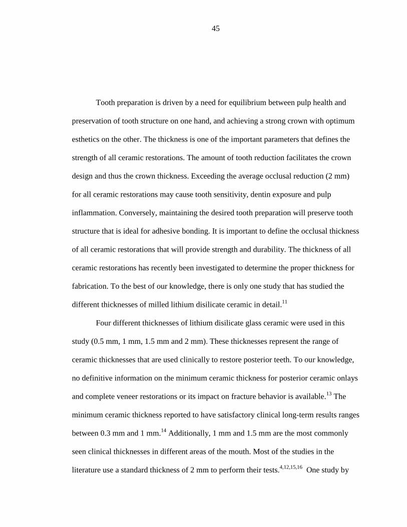
Tooth preparation is driven by a need for equilibrium between pulp health and
preservation of tooth structure on one hand, and achieving a strong crown with optimum
esthetics on the other. The thickness is one of the important parameters that defines the
strength of all ceramic restorations. The amount of tooth reduction facilitates the crown
design and thus the crown thickness. Exceeding the average occlusal reduction (2 mm)
for all ceramic restorations may cause tooth sensitivity, dentin exposure and pulp
inflammation. Conversely, maintaining the desired tooth preparation will preserve tooth
structure that is ideal for adhesive bonding. It is important to define the occlusal thickness
of all ceramic restorations that will provide strength and durability. The thickness of all
ceramic restorations has recently been investigated to determine the proper thickness for
fabrication. To the best of our knowledge, there is only one study that has studied the
different thicknesses of milled lithium disilicate ceramic in detail.11
Four different thicknesses of lithium disilicate glass ceramic were used in this
study (0.5 mm, 1 mm, 1.5 mm and 2 mm). These thicknesses represent the range of
ceramic thicknesses that are used clinically to restore posterior teeth. To our knowledge,
no definitive information on the minimum ceramic thickness for posterior ceramic onlays
and complete veneer restorations or its impact on fracture behavior is available.13
The
minimum ceramic thickness reported to have satisfactory clinical long-term results ranges
between 0.3 mm and 1 mm.14
Additionally, 1 mm and 1.5 mm are the most commonly
seen clinical thicknesses in different areas of the mouth. Most of the studies in the
literature use a standard thickness of 2 mm to perform their tests.4,12,15,16
One study by

46
Dhima et al.11
studied the four different thicknesses of lithium disilicate glass ceramic as
was done in this study and reported similar results. Kelly et al.6
reported a mean failure
load for 1 mm thicknesses of leucite filled porcelain crowns (1610 N) whereas in our
study the 1 mm group showed a mean failure load of (845 N) The reason for the
difference between our study and his may be that fatigue testing in distilled water
lowered the failure loads of the ceramic crown specimens compared to those tested in a
dry environment.17
Adhesive cementation of the ceramic crowns was done using resin cement in our
experiment. Studies have shown that mode of cementation influenced fracture load and
adhesive cementation resulted in higher fracture loads than non-adhesive cementation.4
A
study by Consani et al.17
reported that the resin cement showed the greater tensile
strength values among the different cements used in his study.
Ideally, in-vitro studies of all-ceramic materials should produce failures that are
comparable to those in clinical situations. Repeated chewing and other functions in the
oral cavity subject all-ceramic crowns to fatigue behavior. These forces change over time
in a repeated fashion and could cause the material to fail. In the current study, cyclic
loading was performed prior to static loading in order to simulate some of the stresses a
crown will be subjected to during mastication. Studies have shown that veneered zirconia
(Y-TZP) crowns were chipped due to fatigue encountered in the veneering layer whereas
lithium disilicate glass crowns were fatigue- resistant.18
The failure mode of monolithic
lithium disilicate glass crowns was bulk fracture of the substructure and veneering
porcelain. Literature is short on the effect of cyclic loading on the failure behavior of
lithium disilicate glass ceramic. Therefore, the current study incorporated cyclic fatigue

47
to help to mimic the clinical situation of repeated mastication forces on lithium disilicate
glass ceramic crowns.
Cyclic loading was achieved through a relatively low force repeated over 1x10⁶
cycles. In this study, 300 N was chosen to perform the cyclic loading based on pilot study
results. In the pilot study, samples were fatigued using three different loads (300 N, 350
N and 400 N). It was observed that both 350 N and 400 N caused crowns to fracture
during fatigue loading while 300 N did not cause any cracks or fracture in any of the
samples tested. Dhima et al.10
reported mean failure load of monolithic lithium disilicate
was greater than average posterior masticatory forces (150 N to 340 N). They observed
that lithium disilicate behaves well under low loads and loading outcomes were
accelerated using this protocol. The in-vitro study designs vary considerably, especially
when it comes to the dry or wet testing environment and it is difficult to standardize the
test environment.10
Zhao et al.18
in his study tested veneer application and cyclic loading on the
failure mode of lithium disilicate glass ceramic to determine whether it was an
accelerating factor for failure. He reported that monolithic lithium disilicate glass ceramic
showed superior performance compared to bilayered lithium disilicate glass ceramic,
irrespective of fatigue load application. Carvalho et al.19
showed that all-ceramic crowns
fabricated by a CAD/CAM technique were fatigue resistant and survived beyond the
normal range of masticatory forces (600 N to 900 N). The results of fracture load
obtained for 2-mm thickness (1702 N) were three times higher than the normal range of
posterior mastication (500 N) indicating that this restorative system will tolerate posterior

48
loads satisfactorily. No single study compared data of fatigued and non-fatigued all
ceramic crowns.
Our results are similar to results obtained from Dhima et al.10
who reported a
gradual increase in load to fracture between four different occlusal thicknesses of crowns
(0.5 mm, 1 mm, 1.5 mm and 2 mm). However, there are distinct differences in the design
of the two studies, which makes both studies complement each other toward a better
understanding of the effect of various thicknesses of ceramic on fracture strength. The die
fabrication was milled from a milling unit in the previous study whereas ours was
duplicated using a silicone mold. We used an E4D milling unit to fabricate the lithium
disilicate crowns while CEREC was their machine of choice. They stored their specimens
126 days prior to loading and our specimens were only stored for 24 hours prior to
testing. The load tip in our study was directed towards the functional cusp (buccal) for
lower molars while theirs was subjected to a mouth motion fatigue test: (antagonist
contact-load-slide liftoff). The cyclic load force used was 300 N in an Instron machine in
the current study, while Dhima used a force range between (350 N to 400 N) in a MTS
machine. A water bath was incorporated for our specimens as the test was performed in a
wet environment to resemble the clinical situation.20
However, their test was done in dry
conditions. Results of fracture load may vary whether the test was conducted in wet or
dry situations. Subsequently, the failure pattern that have been observed resembles what
could be seen clinically. This is attributed to testing in wet environment and submerging
the samples in water. Our specimens were fabricated using an epoxy resin material
whereas they used an ultrafine zirconia-silica ceramic. The differences between the
modulus of elasticity of the two materials will give exaggerated results. The tip used in

49
their study was a metal one; we used an epoxy resin tip to more closely match the
modulus of elasticity of the supporting dental structures. They fatigue loaded their
specimens to failure; on the contrary, we fatigued our samples then loaded them to failure
trying to mimic the clinical scenario where teeth are in function for a period of time and
then experience a concentrated loading event.21
Our method was expected to give lower
results than a non-fatigued method although there are no studies comparing results of
fatigued and non-fatigued crowns. This is an area for further research.
Further investigation to compare different thicknesses of pressed and CAD/CAM
lithium disilicate glass ceramic will be helpful to compare results. Also, testing various
types of ceramics with different loading environments (wet versus dry) could aid in
drawing conclusions on the mean failure loads. Selecting different anatomical teeth
(premolars versus molars) would give a better understanding of the impact of force
generation in different regions of the posterior segment of the arch.

50
SUMMARY AND CONCLUSION

51
From these results it can be concluded that:
1. Within the limitation of this in-vitro study, fatigued lithium disilicate glass
ceramic crowns with 1.5-mm and 2-mm thicknesses showed significantly
higher load to fracture compared with the same crown design with 0.5-mm
and 1-mm thicknesses.
2. For clinical application, it is advisable to consider a crown thickness of 1.5
mm or greater of milled lithium disilicate crowns for posterior single molar
teeth.

52
REFERENCES

53
1. Kelly JR, Campbell SD, Bowen HK. Fracture-surface analysis of dental ceramics.
J Prosthet Dent 1989;62:536-41.
2. Kelly JR. Dental ceramics: what is this stuff anyway? J Am Dent Assoc 2008;
139 Suppl:4S-7S.
3. Kheradmandan S, Koutayas SO, Bernhard M, et al. Fracture strength of four
different types of anterior 3-unit bridges after thermo-mechanical fatigue in the dual-axis
chewing simulator. J Oral Rehabil 2001;28:361-9.
4. Wolf D, Bindl A, Schmidlin PR, et al. Strength of CAD/CAM-generated esthetic
ceramic molar implant crowns. Int J Oral Maxillofac Implant 2008;23:609-17.
5. Chen HY, Hickel R, Setcos JC, et al. Effects of surface finish and fatigue testing
on the fracture strength of CAD-CAM and pressed-ceramic crowns. J Prosthet Dent
1999;82:468-75.
6. Kelly JR, Rungruanganunt P, Hunter B, et al. Development of a clinically
validated bulk failure test for ceramic crowns. J Prosthet Dent 2010;104:228-38.
7. Kelly JR, Giordano R, Pober R, et al. Fracture surface analysis of dental ceramics:
clinically failed restorations. Int J Prosthodont 1990;3:430-40.
8. Kelly JR, Nishimura I, Campbell SD. Ceramics in dentistry: historical roots and
current perspectives. J Prosthet Dent 1996;75:18-32.
9. Shenoy A, Shenoy N. Dental ceramics: an update. J Conservative Dent 2010;13:
195-203.
10. Dhima M, Carr AB, Salinas TJ, et al. Evaluation of fracture resistance in aqueous
environment under dynamic loading of lithium disilicate restorative systems for posterior
applications (Pt 2). J Prosthodont 2014; 23:353-7.
11. Albakry M, Guazzato M, Swain MV. Biaxial flexural strength, elastic moduli, and
x-ray diffraction characterization of three pressable all-ceramic materials. J Prosthet Dent
2003;89:374-80.
12. Attia A, Kern M. Influence of cyclic loading and luting agents on the fracture load
of two all-ceramic crown systems. J Prosthet Dent 2004;92:551-6.

54
13. Malament KA, Socransky SS. Survival of Dicor glass-ceramic dental restorations
over 14 years.(Pt 2).Effect of thickness of Dicor material and design of tooth preparation.
J Prosthet Dent 1999;81:662-7.
14. Frankenberger R, Taschner M, Garcia-Godoy F, et al. Leucite-reinforced glass
ceramic inlays and onlays after 12 years. J Adhesive Dent 2008;10:393-8.
15. Fasbinder DJ, Dennison JB, Heys D, et al. A clinical evaluation of chairside
lithium disilicate CAD/CAM crowns: a two-year report. J Am Dent Assoc 2010;141
Suppl 2:10S-14S.
16. Tinschert J, Natt G, Mautsch W, et al. Fracture resistance of lithium disilicate-,
alumina-, and zirconia-based three-unit fixed partial dentures: a laboratory study. Int J
Prosthodont 2001;14:231-8.
17. Consani S, Santos JG, Correr Sobrinho L, et al. Effect of cement types on the
tensile strength of metallic crowns submitted to thermocycling. Brazilian Dent J 2003;
14:193-6.
18. Zhao K, Wei YR, Pan Y, et al. Influence of veneer and cyclic loading on failure
behavior of lithium disilicate glass-ceramic molar crowns. Dent Mater 2014;30:164-71.
19. Carvalho AO, Bruzi G, Giannini M, et al. Fatigue resistance of CAD/CAM
complete crowns with a simplified cementation process. J Prosthet Dent 2014;111:310-7.
20. Borges GA, Caldas D, Taskonak B, et al. Fracture loads of all-ceramic crowns
under wet and dry fatigue conditions. J Prosthodont 2009;18:649-55.
21. Kelly JR. Clinically relevant approach to failure testing of all-ceramic
restorations. J Prosthet Dent 1999;81:652-61.

55
ABSTRACT
56
EFFECTS OF VARIOUS THICKNESSES ON LOAD TO FRACTURE
OF POSTERIOR CAD/CAM LITHIUM DISILICATE
GLASS CERAMIC CROWNS SUBJECTED
TO CYCLIC FATIGUE
by
Nadia Sultan Al-Angari
Indiana University School of Dentistry
Indianapolis, Indiana
Background: New glass ceramics and Computer-Aided Design/Computer
Assisted Manufacture (CAD/CAM) have become common aspects of modern dentistry.
The use of posterior ceramic crowns with a high level of esthetics, fabricated using the
CAD/CAM technology is a current treatment modality. Several materials have been used
to fabricate these crowns, including lithium disilicate glass-ceramics, which have not
been fully investigated in the literature.
Objective: to investigate the load to fracture of lithium disilicate glass ceramic
posterior crowns fabricated by CAD/CAM technology with different material thicknesses
adhesively cemented on epoxy resin.
57
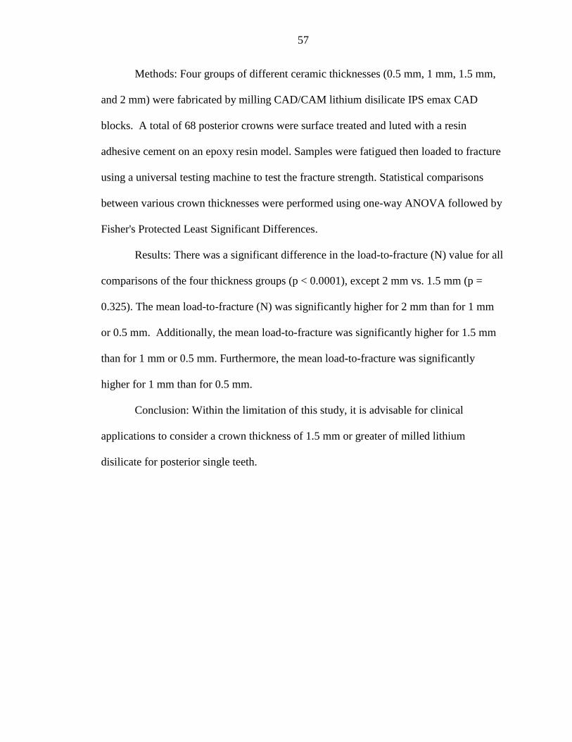
Methods: Four groups of different ceramic thicknesses (0.5 mm, 1 mm, 1.5 mm,
and 2 mm) were fabricated by milling CAD/CAM lithium disilicate IPS emax CAD
blocks. A total of 68 posterior crowns were surface treated and luted with a resin
adhesive cement on an epoxy resin model. Samples were fatigued then loaded to fracture
using a universal testing machine to test the fracture strength. Statistical comparisons
between various crown thicknesses were performed using one-way ANOVA followed by
Fisher's Protected Least Significant Differences.
Results: There was a significant difference in the load-to-fracture (N) value for all
comparisons of the four thickness groups (p < 0.0001), except 2 mm vs. 1.5 mm (p =
0.325). The mean load-to-fracture (N) was significantly higher for 2 mm than for 1 mm
or 0.5 mm. Additionally, the mean load-to-fracture was significantly higher for 1.5 mm
than for 1 mm or 0.5 mm. Furthermore, the mean load-to-fracture was significantly
higher for 1 mm than for 0.5 mm.
Conclusion: Within the limitation of this study, it is advisable for clinical
applications to consider a crown thickness of 1.5 mm or greater of milled lithium
disilicate for posterior single teeth.

CURRICULUM VITAE

Nadia Al-Angari
September 1982 Born in Kansas, USA
August 2000 to July 2007 Bachelor of Dentistry and Surgery (BDS)
King Saud University, College of Dentistry
Riyadh, Saudi Arabia
January 2008 to August 2008 Dentist, King Abdulaziz Medical City,
National Guard, Health Affairs, Riyadh, Saudi
Arabia
September 2008 to August 2010 Advanced Education in General Dentistry
(AEGD) Residency, King Abdulaziz Medical
City, National Guard Health Affiars, Riyadh,
Saudi Arabia
September 2010 to January 2011 AGD Dentist, National Guard Primary Care
Clinics, Riyadh, Saudi Arabia
January 2011 to May 2011 Prosthodontic Scholar, Prosthodontic
Department, King Abdulaziz Medical
City, National Guard Health Affiars, Riyadh,
Saudi Arabia
May 2011 to June 2015 MSD Program (Prosthodontics) Indiana
University School of Dentistry, Indianapolis,
Indiana, USA
Professional Organizations
The Saudi Dental Society
The American College of Prosthodontics
The Royal College of Dentists of Canada
The John F. Johnston Society