Effects of supplemental viscous damping on seismic response of asymmetric-plan systems
17
EARTHQUAKE ENGINEERING AND STRUCTURAL DYNAMICS, VOL. 27, 125—141 (1998) EFFECTS OF SUPPLEMENTAL VISCOUS DAMPING ON SEISMIC RESPONSE OF ASYMMETRIC-PLAN SYSTEMS RAKESH K. GOEL* Department of Civil and Environmental Engineering, Cal Poly State University, San Luis Obispo, CA 93407, U.S.A. SUMMARY Coupling between lateral and torsional motions may lead to much larger edge deformations in asymmetric-plan systems compared to systems with a symmetric plan. Supplemental viscous damping has been found to be effective in reducing deformations in the symmetric-plan system. This investigation examined how supplemental damping affects the edge deformations in asymmetric-plan systems. First, the parameters that characterize supplemental viscous damping and its plan-wise distribution were identified, and then the effects of these parameters on edge deformations were investigated. It was found that supplemental damping reduces edge deformations and that reductions by a factor of up three are feasible with proper selection of system parameters. Furthermore, viscous damping may be used to reduce edge deformations in asymmetric-plan systems to levels equal to or smaller than those in the corresponding symmetric-plan system. ( 1998 John Wiley & Sons, Ltd. Earthquake Engng. Struct. Dyn., 27, 125—141 (1998) KEY WORDS: asymmetric buildings; earthquake response; passive control; plan asymmetry; protective systems; seismic response; supplemental damping; torsion INTRODUCTION It is well known that asymmetric-plan buildings are especially vulnerable to earthquakes. It is therefore not surprising that numerous investigations in the past have focused on the earthquake behaviour of asymmet- ric-plan systems; references are available in reports by Hejal and Chopra,1 Goel and Chopra,2 or in a state-of-the-art review paper by Rutenberg.3 As a result, there has been much improvement in our understanding of how plan asymmetry influences the response of buildings to earthquakes. Procedures to account for undesirable effects of plan asymmetry, such as increased force and ductility demands on lateral load-resisting elements, have been developed and incorporated into many seismic codes.4 However, addi- tional research is needed to develop techniques that will control excessive earthquake-induced deformations in asymmetric-plan buildings. The excessive deformations may lead to premature failure in brittle, non- ductile elements and may result in a sudden loss of the building’s strength and stiffness leading to eventual failure. Excessive edge deformation may also cause pounding between closely spaced adjacent buildings. In general, excessive deformation in asymmetric-plan buildings may be reduced by redistributing the stiffness and/or mass properties to minimize the stiffness eccentricity. For many new structures, such redistribution may be possible at an early design stage, but such redistribution may not always be feasible because of architectural or functional constraints. It may not be feasible for existing structures because of the significant inconvenience to the occupants. * Correspondence to: R. K. Goel, Department of Civil and Environmental Engineering, California Polytechnic State University, San Luis Obispo, CA 93407, U.S.A. CCC 0098—8847/98/020125—17$17·50 Received 24 May 1997 ( 1998 John Wiley & Sons, Ltd. Revised 26 August 1997
Transcript of Effects of supplemental viscous damping on seismic response of asymmetric-plan systems

EARTHQUAKE ENGINEERING AND STRUCTURAL DYNAMICS, VOL. 27, 125—141 (1998)
EFFECTS OF SUPPLEMENTAL VISCOUS DAMPING ON SEISMICRESPONSE OF ASYMMETRIC-PLAN SYSTEMS
RAKESH K. GOEL*
Department of Civil and Environmental Engineering, Cal Poly State University, San Luis Obispo, CA 93407, U.S.A.
SUMMARY
Coupling between lateral and torsional motions may lead to much larger edge deformations in asymmetric-plan systemscompared to systems with a symmetric plan. Supplemental viscous damping has been found to be effective in reducingdeformations in the symmetric-plan system. This investigation examined how supplemental damping affects the edgedeformations in asymmetric-plan systems. First, the parameters that characterize supplemental viscous damping and itsplan-wise distribution were identified, and then the effects of these parameters on edge deformations were investigated. Itwas found that supplemental damping reduces edge deformations and that reductions by a factor of up three are feasiblewith proper selection of system parameters. Furthermore, viscous damping may be used to reduce edge deformations inasymmetric-plan systems to levels equal to or smaller than those in the corresponding symmetric-plan system. ( 1998John Wiley & Sons, Ltd.
Earthquake Engng. Struct. Dyn., 27, 125—141 (1998)
KEY WORDS: asymmetric buildings; earthquake response; passive control; plan asymmetry; protective systems; seismicresponse; supplemental damping; torsion
INTRODUCTION
It is well known that asymmetric-plan buildings are especially vulnerable to earthquakes. It is therefore notsurprising that numerous investigations in the past have focused on the earthquake behaviour of asymmet-ric-plan systems; references are available in reports by Hejal and Chopra,1 Goel and Chopra,2 or ina state-of-the-art review paper by Rutenberg.3 As a result, there has been much improvement in ourunderstanding of how plan asymmetry influences the response of buildings to earthquakes. Procedures toaccount for undesirable effects of plan asymmetry, such as increased force and ductility demands on lateralload-resisting elements, have been developed and incorporated into many seismic codes.4 However, addi-tional research is needed to develop techniques that will control excessive earthquake-induced deformationsin asymmetric-plan buildings. The excessive deformations may lead to premature failure in brittle, non-ductile elements and may result in a sudden loss of the building’s strength and stiffness leading to eventualfailure. Excessive edge deformation may also cause pounding between closely spaced adjacent buildings.
In general, excessive deformation in asymmetric-plan buildings may be reduced by redistributing thestiffness and/or mass properties to minimize the stiffness eccentricity. For many new structures, suchredistribution may be possible at an early design stage, but such redistribution may not always be feasiblebecause of architectural or functional constraints. It may not be feasible for existing structures because of thesignificant inconvenience to the occupants.
* Correspondence to: R. K. Goel, Department of Civil and Environmental Engineering, California Polytechnic State University, SanLuis Obispo, CA 93407, U.S.A.
CCC 0098—8847/98/020125—17$17·50 Received 24 May 1997( 1998 John Wiley & Sons, Ltd. Revised 26 August 1997

In recent years, the role of supplemental damping or energy dissipation devices in reducing the earthquakeresponse of structures has been the subject of many investigations;5~18 a comprehensive summary isavailable elsewhere.8 Although these investigation have led to much improvement in our understanding ofhow such devices improve the sesimic performance of structures, they were primarily focused on the seismicbehaviour of symmetric-plan systems. A few recent investigations have been concerned with the seismicbehaviour of asymmetric-plan systems with supplemental devices.19~22 However, there has been a lack ofeffort towards developing a fundamental understanding of how these devices and their plan-wise distributioninfluence the lateral—torsional coupling in asymmetric-plan systems.
With this aim, the objectives of this exploratory investigation are (1) to identify the system parameters thatcontrol the seismic response of asymmetric-plan systems with fluid viscous dampers; and (2) to investigate theeffects of the controlling parameters on edge deformations in asymmetric-plan systems. System behaviour islimited to the linearly elastic range. This simplifying assumption is suitable for investigating the seismicbehaviour of asymmetric-plan systems with brittle, non-ductile resisting elements, that should remain nearlyelastic during earthquake loading. The seismic response of asymmetric structures responding in the inelasticrange will be investigated during a later phase of this research program.
SYSTEM AND GROUND MOTION
One-storey system
The system considered was the idealized one-storey building of Figure 1 consisting of a rigid decksupported by structural elements (wall, columns, moment-frames, braced-frames, etc.) in each of the twoorthogonal directions. In addition, the system included fluid viscous dampers (FVDs) incorporated into thebracing system. The mass properties of the system were assumed to be symmetric about both the X- and½-axis whereas the stiffness and the damper properties were considered to be symmetric only about theX-axis.
The centre of mass (CM) of the system was defined as the centroid of inertia forces when the systemis subjected to a uniform translational acceleration in the direction under consideration. Since the masswas uniformly distributed about both the X- and ½-axis, the CM coincided with the geometric centre of thedeck.
The centre of supplemental damping (CSD) was defined as the centroid of damper forces when the systemis subjected to a uniform translational velocity in the direction under consideration. The lack of symmetry inthe damper properties about the ½-axis was characterized by the supplemental damping eccentricity, e
4$,
defined as the distance between the CM and the CSD.The centre of rigidity (CR) was defined as the point on the deck through which application of a static
horizontal force causes no rotation of the deck.1 For the one-storey system considered in this investigation,CR was also the centroid of resisting forces in structural elements when the system is subjected to a uniformtranslational displacement in the direction under consideration. The lack of symmetry in the stiffnessproperties about the ½-axis was characterized by the stiffness eccentricities, e, defined as the distance betweenthe CM and the CR. With both CM and CR defined, the edge that is on the same side of the CM as the CRwas denoted as the stiff edge and the other edge was designated as the flexible edge (Figure 1(a)).
The corresponding symmetric-plan system was defined as a system with no FVDs and coincidental CMand CR but with relative locations and stiffnesses of all resisting elements identical to those in theasymmetric-plan system.
Ground motion
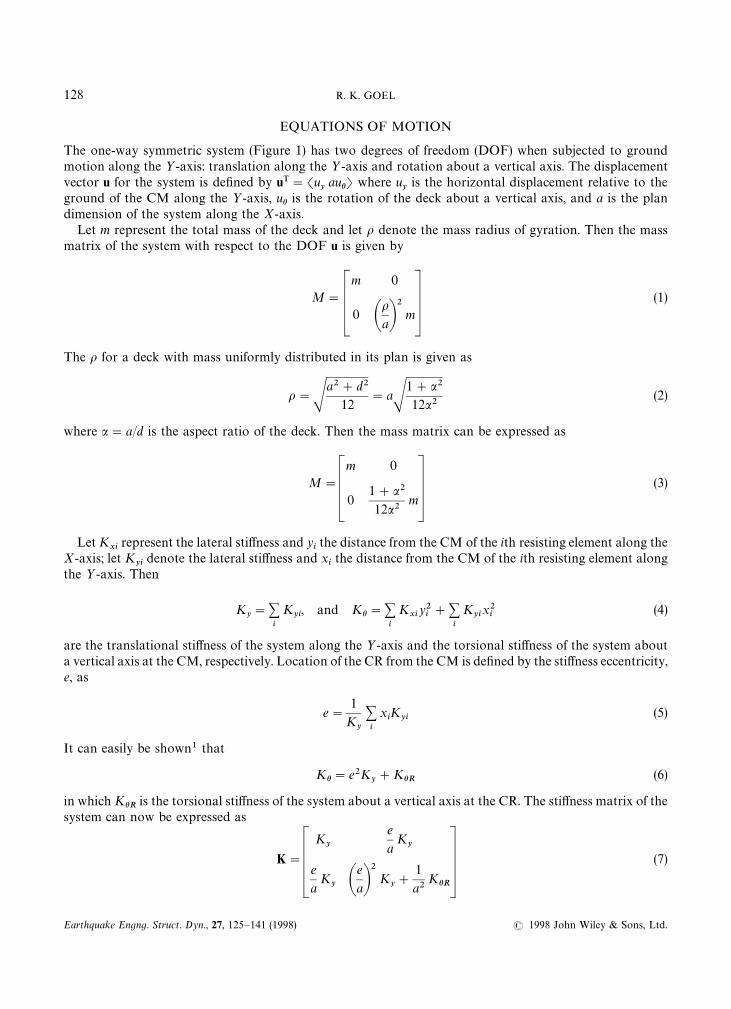
The ground motion considered is the North—South (360°) component recorded at the Sylmar CountyHospital parking lot during the 1994 Northridge earthquake. The peak values of the ground acceleration,velocity and displacement recorded at this site were 826·8 cm/s2, 128·9 cm/s, and 32·55 cm, respectively.
126 R. K. GOEL
Earthquake Engng. Struct. Dyn., 27, 125—141 (1998) ( 1998 John Wiley & Sons, Ltd.
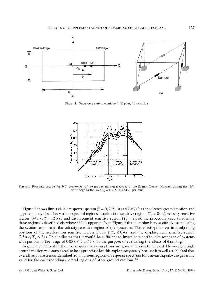
Figure 1. One-storey system considered: (a) plan, (b) elevation
Figure 2. Response spectra for 360° component of the ground motion recorded at the Sylmar County Hospital during the 1994Northridge earthquake ; f"0, 2, 5, 10 and 20 per cent
Figure 2 shows linear elastic response spectra (f"0, 2, 5, 10 and 20%) for the selected ground motion andapproximately identifies various spectral regions: acceleration sensitive region (¹
y(0·4 s), velocity sensitive
region (0·4 s(¹y(2·5 s), and displacement sensitive region (¹
y'2·5 s); the procedure used to identify
these regions is described elsewhere.23 It is apparent from Figure 2 that damping is most effective at reducingthe system response in the velocity sensitive region of the spectrum. This effect spills over into adjoiningportions of the acceleration sensitive region (0·05 s)¹
y)0·4 s) and the displacement sensitive region
(2·5 s)¹y)3 s). This indicates that it would be sufficient to investigate earthquake response of systems
with periods in the range of 0·05 s)¹y)3 s for the purpose of evaluating the effects of damping.
In general, details of earthquake response may vary from one ground motion to the next. However, a singleground motion was considered to be appropriate for this exploratory study because it is well established thatoverall response trends identified from various regions of response spectrum for one earthquake are generallyvalid for the corresponding spectral regions of other ground motions.23
EFFECTS OF SUPPLEMENTAL VISCOUS DAMPING ON SEISMIC RESPONSE 127
( 1998 John Wiley & Sons, Ltd. Earthquake Engng. Struct. Dyn., 27, 125—141 (1998)
EQUATIONS OF MOTION
The one-way symmetric system (Figure 1) has two degrees of freedom (DOF) when subjected to groundmotion along the ½-axis: translation along the ½-axis and rotation about a vertical axis. The displacementvector u for the system is defined by uT"Su
yauhT where u
yis the horizontal displacement relative to the
ground of the CM along the ½-axis, uh is the rotation of the deck about a vertical axis, and a is the plandimension of the system along the X-axis.
Let m represent the total mass of the deck and let o denote the mass radius of gyration. Then the massmatrix of the system with respect to the DOF u is given by
M"
m 0
0 AoaB
2m
(1)
The o for a deck with mass uniformly distributed in its plan is given as
o"Sa2#d2
12"aS
1#a2
12a2(2)
where a"a/d is the aspect ratio of the deck. Then the mass matrix can be expressed as
M"
m 0
01#a2
12a2m
(3)
Let Kxi
represent the lateral stiffness and yithe distance from the CM of the ith resisting element along the
X-axis; let Kyi
denote the lateral stiffness and xithe distance from the CM of the ith resisting element along
the ½-axis. Then
Ky"+
i
Kyi, and Kh"+
i
Kxi
y2i#+
i
Kyix2i
(4)
are the translational stiffness of the system along the ½-axis and the torsional stiffness of the system abouta vertical axis at the CM, respectively. Location of the CR from the CM is defined by the stiffness eccentricity,e, as
e"1
Ky
+i
xiK
yi(5)
It can easily be shown1 that
Kh"e2Ky#KhR (6)
in which KhR is the torsional stiffness of the system about a vertical axis at the CR. The stiffness matrix of thesystem can now be expressed as
K"
Ky
e
aK
y
e
aK
y Ae
aB2
Ky#
1
a2KhR
(7)
128 R. K. GOEL
Earthquake Engng. Struct. Dyn., 27, 125—141 (1998) ( 1998 John Wiley & Sons, Ltd.

With both mass and stiffness matrices known, the stiffness-and-mass-proportional damping matrix of thesystem can be determined as
C"a0M#a
1K (8)
in which constants a0
and a1
depend on damping ratios, f1
and f2, in the two vibration modes of the system.
The damping matrix of equation (8) accounts for the natural capacity of the system to dissipate energy.Let C
xirepresent the velocity-proportional damping coefficient and y
ithe distance from the CM of the ith
fluid viscous damper (FVD) along the X-axis; let Cyi
denote the damping coefficient and xithe distance from
the CM of the ith FVD along the ½-axis. Then
Cy"+
i
Cyi, and Ch"+
i
Cxi
y2i#+
i
Cyix2i
(9)
are the translational damping coefficient of the system along the ½-axis and the torsional damping coefficientof the system about a vertical axis at the CM, respectively. Location of the CSD from the CM is defined bythe supplemental damping eccentricity, e
4$, as
e4$"
1
Cy
+i
xiC
yi(10)
Using a transformation similar to that in equation (6), Ch can be expressed as
Ch"e24$C
y#Ch4$ (11)
in which Ch4$ is the torsional damping coefficient of the system about a vertical axis at the CSD. The dampingmatrix of the system due to FVDs can now be expressed as
C4$"
Cy
e4$a
Cy
e4$a
Cy A
e4$a B
2C
y#
1
a2Ch4$
(12)
Let us define the supplemental damping radius of gyration, o4$
, as
o4$"S
Ch4$C
y
(13)
The damping matrix of equation (12) can then be expressed as
C4$"
Cy
e4$a
Cy
e4$a
Cy GA
e4$a B
2#A
o4$a B
2
H Cy
(14)
EFFECTS OF SUPPLEMENTAL VISCOUS DAMPING ON SEISMIC RESPONSE 129
( 1998 John Wiley & Sons, Ltd. Earthquake Engng. Struct. Dyn., 27, 125—141 (1998)
The equations of motion for the one-way symmetric system (Figure 1) subjected to ground accelerationu'along the ½-axis are
m 0
0 m1#a2
12a2
Guy
auhH#Aa0m 0
0 m1#a2
12a2
#a1
Ky
e
aK
y
e
aK
y Ae
aB2
Ky#
1
a2KhR B G uR
yauR hH
#
Cy
e4$a
Cy
e4$a
Cy GA
e4$a B
2#A
o4$a B
2
H Cy
GuRy
auR hH#K
y
e
aK
y
e
aK
y Ae
aB2
Ky#
1
a2KhR
Guy
auhH"!Gm
0H u'
(15)
After dividing by m and some algebraic manipulations, equation (15) leads to
1 0
01#a2
12a2
Guy
auhH#Aa01 0
01#a2
12a2
#a1u2
y
1 eN
eN eN 2#1#a2
12a2)2h B G uR
yauR hH
#2uyf4$ C
1
eN4$
eN4$
eN 24$#oN 2
4$D G
uRy
auR hH#u2y
1 eN
eN eN 2#1#a2
12a2)2hG
uy
auhH"!G1
0H u'
(16)
in which uy"JK
y/m"transverse vibration frequency; )h"uh/uy
"ratio of the torsional and transversefrequencies with uh"JKhR/mo2"torsional frequency; f
4$"C
y/2mu
y"supplemental damping ratio;
eN"e%a"normalized stiffness eccentricity; eN4$"e
4$%a"normalized supplemental damping eccentri-
city; and oN4$"o
4$%a"normalized supplemental damping radius of gyration.
CONTROLLING SYSTEM PARAMETERS
Equation (16) indicates that the linear elastic response of one-storey, asymmetric-plan systems with FVDsdepends on two sets of parameters. The first set of parameters corresponding to the system without FVDsconsists of (1) transverse vibration period, ¹
y"2n/u
y(u
y"transverse vibration frequency) of the corres-
ponding symmetric-plan system; (2) normalized stiffness eccentricity, eN ; (3) ratio of the torsional andtransverse frequencies, )h; (4) aspect ratio, a; and (5) mass and stiffness proportional constants, a
0and a
1,
which in turn depend on the natural damping ratios, f1
and f2, in the two vibration modes of the system. The
aspect ratio was included as one of the system parameters because it facilitated a more appealing definition ofthe stiffness eccentricity as a percentage (or fraction) of the plan dimension. If the stiffness eccentricity werenormalized by the mass radius of gyration, the aspect ratio would not be an independent system parameter.Since physical interpretation of many of these parameters has been discussed in an earlier publication,1 theyare not described in detail here.
The second set of parameters corresponding to supplemental damping consists of (1) supplementaldamping ratio, f
4$; (2) normalized supplemental damping eccentricity, eN
4$; and (3) normalized supplemental
damping radius of gyration, oN4$. f
4$is indicative of the amount of additional damping, as a fraction of the
critical value, provided by FVDs in the transverse vibration mode of the corresponding symmetric-plansystem; and eN
4$is indicative of how unevenly FVDs are located within the system plan. A zero value of
eN4$
implies that FVDs are located symmetrically about the CM, whereas non-zero values (eN4$
can take on
130 R. K. GOEL
Earthquake Engng. Struct. Dyn., 27, 125—141 (1998) ( 1998 John Wiley & Sons, Ltd.
a positive as well as a negative value) indicate uneven distribution. Since FVDs cannot be located outside thesystem plan, the limiting values of eN
4$are !0·5 and 0·5; these values correspond to all dampers located either
on the flexible edge or on the stiff edge (Figure 1). oN4$
indicates how much farther apart from the CSD theFVDs are located. This parameter is also indicative of the damping in the torsional mode of vibration of thecorresponding symmetric-plan system. Zero value of oN
4$implies that all FVDs are located at the CSD and
that they provide zero damping in the torsional mode, whereas larger values indicate that FVDs are locatedfarther from the CSD and that damping is increased in the torsional mode.
It should be noted that the system damping was specified as sum of (1) the stiffness and mass proportionalclassical damping depending on f
1and f
2; and (2) the supplemental damping due to the FVDs characterized
by f4$, eN
4$and oN
4$. Clearly, systems without FVDs would possess only classical damping. Also note that the
locations of dampers in this investigation were not necessarily restricted to system edges; they are shown tobe on edges only for the purpose of clarity (Figure 1(b)).
The damping coefficient of an FVD, in general, depends on the frequency and amplitude of motion as wellas on the operating temperature.8 Furthermore, FVD may also exhibit some viscoelastic force-deformationbehaviour, i.e., the force in an FVD depends not only on the velocity but also on the displacement. However,due to exploratory nature of this investigation, these parameters were not considered; they will be included ata later stage.
SELECTED SYSTEM PARAMETERS
Responses are presented for the following values of system parameters. Values of ¹y
were selected in therange of 0·05—3 s to represent many low-rise and mid-rise buildings for which supplemental damping isexpected to significantly influence the response. The selected value of )h"1 represents systems with strongcoupling between lateral and torsional motions in the elastic range. In order to investigate how the effects ofsupplemental damping differ for torsionally-very-flexible and torsionally-very-stiff systems, values of)h"0·5 and 2·0 were also considered. The normalized stiffness eccentricity eN was selected as 0·2 whichrepresents an eccentricity of 20 per cent of the plan dimension. The aspect ratios, a, of the selected systemswere fixed at two. The constants a
0and a
1in equation (8) were selected such that damping ratios in both
vibration modes of the system with eN fixed were equal to 5 per cent, i.e., f1"f
2"f"5 per cent.
The value of f4$
was fixed at 10 per cent for most cases; for a limited number of cases, however, variationsof f
4$in the range of 0—50 per cent were considered. In general, three values of eN
4$"0·2, 0 and !0·2
were selected. The first corresponds to the supplemental damping eccentricity equal to and in the samedirection as the selected stiffness eccentricity, i.e., coincidental locations of the CR and CSD. The secondvalue corresponds to even distribution of FVDs about the CM and thus the identical location of the CM andCSD. The last value corresponds to equal values of the two eccentricities, but with the CSD located on theopposite side of the CM from the CR. For selected cases, variations of e6
4$in the range of !0·5—0·5 were also
considered. The selected values of oN4$"0, 0·2 and 0·5 represent low, medium, and large spread of FVDs
about the CSD.
RESPONSE QUANTITIES
The response quantities of interest were the peak deformations u&and u
4at the flexible and the stiff edge,
respectively, of the system. If the system plan were symmetric, these deformations would be identical, i.e.,u&"u
4"u
0. The deviations in u
&and u
4from u
0are indicative of the effects of plan asymmetry. Therefore, the
response quantities selected in this investigation were the deformations of the flexible and stiff edges inasymmetric-plan system normalized by the deformation of the corresponding symmetric-plan system,uN&"u
&%u
0and uN
4"u
4%u
0. A value of the normalized edge deformation by more than one indicates
a larger edge deformation in the asymmetric-plan system as compared to the corresponding symmetric-plansystem; conversely, a value of normalized edge deformation smaller than one implies a smaller edge
EFFECTS OF SUPPLEMENTAL VISCOUS DAMPING ON SEISMIC RESPONSE 131
( 1998 John Wiley & Sons, Ltd. Earthquake Engng. Struct. Dyn., 27, 125—141 (1998)
deformation in the asymmetric-plan system. It is useful to note that no FVDs were included in thecorresponding symmetric-plan system; the system possessed only classical damping with f
1"f
2"f"5%.
The peak values of edge deformations were selected to be the response quantities of interest, rather thanpeak values of translational and rotational displacements at CM or CR,1 because they are indicative of (1)deformation demands on outermost lateral load resisting elements of the system, (2) deformation demands onthe cladding system, which generally consists of brittle, non-ductile elements sensitive to excessive deforma-tions, and (3) clear spacing required between adjacent buildings in order to avoid pounding. Peak values ofthe translational and rotational deformations at CM (or CR) may occur at different times and cannot becombined directly to obtain deformation demands at some other location on the system plan.
EFFECTS OF PLAN ASYMMETRY
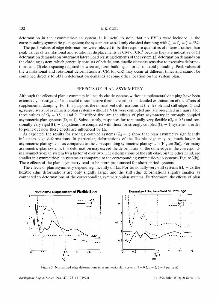
Although the effects of plan asymmetry in linearly elastic systems without supplemental damping have beenextensively investigated,1 it is useful to summarize them here prior to a detailed examination of the effects ofsupplemental damping. For this purpose, the normalized deformations at the flexible and stiff edges, uN
&and
uN4, respectively, of asymmetric-plan systems without FVDs were computed and are presented in Figure 3 for
three values of )h"0·5, 1 and 2. Described first are the effects of plan asymmetry in strongly coupledasymmetric-plan systems ()h"1). Subsequently, responses for torsionally-very-flexible ()h"0·5) and tor-sionally-very-rigid ()h"2) systems are compared with those for strongly coupled ()h"1) systems in orderto point out how these effects are influenced by )h.
As expected, the results for strongly coupled systems ()h"1) show that plan asymmetry significantlyinfluences edge deformations. In particular, deformations of the flexible edge may be much larger inasymmetric-plan systems as compared to the corresponding symmetric-plan system (Figure 3(a)). For manyasymmetric-plan systems, this deformation may exceed the deformation of the same edge in the correspond-ing symmetric-plan system by a factor of over two. The deformations of the stiff edge, on the other hand, aresmaller in asymmetric-plan systems as compared to the corresponding symmetric-plan systems (Figure 3(b)).These effects of the plan asymmetry tend to be more pronounced for short-period systems.
The effects of plan asymmetry depend significantly on )h. For torsionally-very-stiff systems ()h"2), theflexible edge deformations are only slightly larger and the stiff edge deformations slightly smaller ascompared to deformations of the corresponding symmetric-plan systems. Furthermore, the effects of plan
Figure 3. Normalized edge deformations in asymmetric-plan systems (eN"0·2; a"2; f"5 per cent)
132 R. K. GOEL
Earthquake Engng. Struct. Dyn., 27, 125—141 (1998) ( 1998 John Wiley & Sons, Ltd.
asymmetry are essentially independent of the system period. For torsionally-very-flexible systems ()h"0·5),however, deformations at both edges may be significantly larger as compared to the correspondingsymmetric-plan systems, and these effects show strong dependence on the system period. These observationsare consistent with previous findings.1
It becomes apparent from the summary presented in this section that brittle, non-ductile elements(structural or non-structural), which are sensitive to excessive deformations, when located near the edge mayexperience much larger damage in asymmetric-plan systems as compared to the same elements in thecorresponding symmetric-plan systems. This may occur primarily for elements near the flexible edge ofasymmetric-plan systems; for torsionally-very-flexible systems ()h"0·5), elements located near the stiff edgemay also be vulnerable.
EFFECTS OF SUPPLEMENTAL DAMPING
Effects of various system parameters related to the supplemental damping — eN4$, oN
4$, and f
4$— are evaluated
by comparing the normalized edge deformations, uN&and uN
4, of systems with supplemental dampers with those
of systems without supplemental dampers; the later is denoted as the f4$"0 case. Following is a detailed
discussion of these effects.
Supplemental damping eccentricity
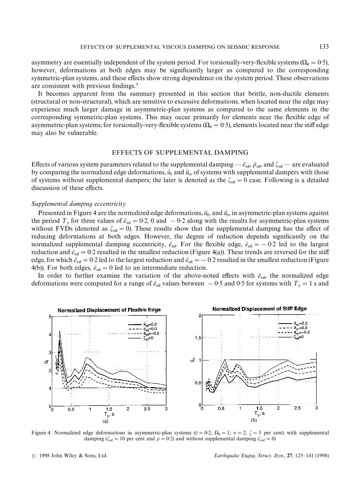
Presented in Figure 4 are the normalized edge deformations, uN&, and uN
4, in asymmetric-plan systems against
the period ¹yfor three values of eN
4$"0·2, 0 and !0·2 along with the results for asymmetric-plan systems
without FVDs (denoted as f4$"0). These results show that the supplemental damping has the effect of
reducing deformations at both edges. However, the degree of reduction depends significantly on thenormalized supplemental damping eccentricity, eN
4$. For the flexible edge, eN
4$"!0·2 led to the largest
reduction and eN4$"0·2 resulted in the smallest reduction (Figure 4(a)). These trends are reversed for the stiff
edge, for which eN4$"0·2 led to the largest reduction and eN
4$"!0·2 resulted in the smallest reduction (Figure
4(b)). For both edges, eN4$"0 led to an intermediate reduction.
In order to further examine the variation of the above-noted effects with eN4$, the normalized edge
deformations were computed for a range of eN4$
values between !0·5 and 0·5 for systems with ¹y"1 s and
Figure 4. Normalized edge deformations in asymmetric-plan systems (eN"0·2; )h"1; a"2; f"5 per cent) with supplementaldamping (f
4$"10 per cent and oN "0·2) and without supplemental damping (f
4$"0)
EFFECTS OF SUPPLEMENTAL VISCOUS DAMPING ON SEISMIC RESPONSE 133
( 1998 John Wiley & Sons, Ltd. Earthquake Engng. Struct. Dyn., 27, 125—141 (1998)

Figure 5. Normalized edge deformations in asymmetric-plan systems (eN"0·2; )h"1; a"2; f"5 per cent; ¹y"1 s) with supple-
mental damping (f4$"10 per cent)
are presented in Figure 5; the extreme values of eN4$"!0·5 and 0·5 correspond to all FVDs located either at
the flexible or at the stiff edge, respectively. Although the results are presented for three values of oN4$"0, 0·2
and 0·5, the discussion in this section will focus on systems with oN4$"0·2, the value selected for systems
considered in Figure 4; results for oN4$"0 and 0·5 will be utilized in the next section, where the effects of
oN4$
are discussed. These results show that deformation of the flexible edge decreases and that of the stiff edgeincreases as eN
4$decreases from 0·5 to !0·5, i.e., the CSD moves from the right to the left of the system plan
(Figure 1(a)). These results also show that uN&is the smallest for eN
4$"!0·5 (Figure 5(a)), indicating that the
largest reduction in deformation of the flexible edge would be obtained by concentrating all FVDs at theflexible edge. A reduction by a factor of nearly two, when compared to the symmetric distribution (eN
4$"0),
can be achieved for the selected system. The stiff edge deformation, on the other hand, is the smallest foreN4$"5·0, implying that the largest reduction would be obtained by locating all FVDs at the stiff edge (Figure
5(b)). The reduction for this edge by a factor one-and-a-half compared to the symmetric distribution (eN4$"0),
while smaller than that for the flexible edge, it is still significant.Since the effects of plan asymmetry depend significantly on the uncoupled lateral-to-torsional frequency
ratio, )h, results were also generated for torsionally-very-flexible ()h"0·5) and torsionally-very-stiff()h"2·0) systems and are presented in Figures 6 and 7. It is apparent from these figures that the effects ofsupplemental damping and damping eccentricity tend to be more pronounced on the flexible edge oftorsionally-very-flexible systems ()h"0·5) as compared to strongly coupled systems ()h"1) (Figures 6(a)and 4(a)). In particular, providing supplemental damping (curve for f
4$"0 compared to other curves) and
a changes in eN4$
from 0·2 to !0·2 (curve for various values of eN4$) resulted in a much larger reduction in the
flexible edge deformations of torsionally-very-flexible systems. This effect is more pronounced for systemswith ¹
y"0·5—1·5 s. As noted previously (Figure 3(b)), the stiff edge deformations of torsionally-very-flexible
systems may exceed those in the corresponding symmetric-plan systems. The supplemental damping reducesthe deformation of this edge as well; however, this reduction is not very sensitive to eN
4$(Figure 6(b)).
While supplemental damping reduces edge deformations in torsionally-very-stiff systems ()h"2), thereductions tend to be smaller than those for systems with )h"1 (Figures 7 and 4). Furthermore, thesereductions are not very sensitive to eN
4$, as is apparent from nearly identical curves for eN
4$"0·2, 0 and !0·2
(Figure 7).
134 R. K. GOEL
Earthquake Engng. Struct. Dyn., 27, 125—141 (1998) ( 1998 John Wiley & Sons, Ltd.
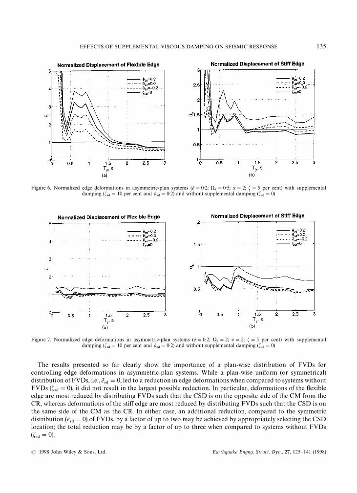
Figure 6. Normalized edge deformations in asymmetric-plan systems (eN"0·2; )h"0·5; a"2; f"5 per cent) with supplementaldamping (f
4$"10 per cent and oN
4$"0·2) and without supplemental damping (f
4$"0)
Figure 7. Normalized edge deformations in asymmetric-plan systems (eN"0·2; )h"2; a"2; f"5 per cent) with supplementaldamping (f
4$"10 per cent and oN
4$"0·2) and without supplemental damping (f
4$"0)
The results presented so far clearly show the importance of a plan-wise distribution of FVDs forcontrolling edge deformations in asymmetric-plan systems. While a plan-wise uniform (or symmetrical)distribution of FVDs, i.e., eN
4$"0, led to a reduction in edge deformations when compared to systems without
FVDs (f4$"0), it did not result in the largest possible reduction. In particular, deformations of the flexible
edge are most reduced by distributing FVDs such that the CSD is on the opposite side of the CM from theCR, whereas deformations of the stiff edge are most reduced by distributing FVDs such that the CSD is onthe same side of the CM as the CR. In either case, an additional reduction, compared to the symmetricdistribution (eN
4$"0) of FVDs, by a factor of up to two may be achieved by appropriately selecting the CSD
location; the total reduction may be by a factor of up to three when compared to systems without FVDs(f
4$"0).
EFFECTS OF SUPPLEMENTAL VISCOUS DAMPING ON SEISMIC RESPONSE 135
( 1998 John Wiley & Sons, Ltd. Earthquake Engng. Struct. Dyn., 27, 125—141 (1998)
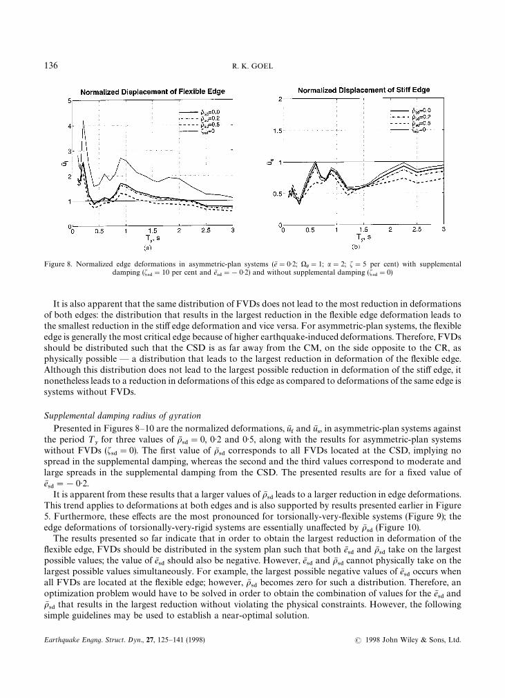
Figure 8. Normalized edge deformations in asymmetric-plan systems (eN"0·2; )h"1; a"2; f"5 per cent) with supplementaldamping (f
4$"10 per cent and eN
4$"!0·2) and without supplemental damping (f
4$"0)
It is also apparent that the same distribution of FVDs does not lead to the most reduction in deformationsof both edges: the distribution that results in the largest reduction in the flexible edge deformation leads tothe smallest reduction in the stiff edge deformation and vice versa. For asymmetric-plan systems, the flexibleedge is generally the most critical edge because of higher earthquake-induced deformations. Therefore, FVDsshould be distributed such that the CSD is as far away from the CM, on the side opposite to the CR, asphysically possible — a distribution that leads to the largest reduction in deformation of the flexible edge.Although this distribution does not lead to the largest possible reduction in deformation of the stiff edge, itnonetheless leads to a reduction in deformations of this edge as compared to deformations of the same edge issystems without FVDs.
Supplemental damping radius of gyration
Presented in Figures 8—10 are the normalized deformations, uN&and uN
4, in asymmetric-plan systems against
the period ¹y
for three values of oN4$"0, 0·2 and 0·5, along with the results for asymmetric-plan systems
without FVDs (f4$"0). The first value of oN
4$corresponds to all FVDs located at the CSD, implying no
spread in the supplemental damping, whereas the second and the third values correspond to moderate andlarge spreads in the supplemental damping from the CSD. The presented results are for a fixed value ofeN4$"!0·2.It is apparent from these results that a larger values of oN
4$leads to a larger reduction in edge deformations.
This trend applies to deformations at both edges and is also supported by results presented earlier in Figure5. Furthermore, these effects are the most pronounced for torsionally-very-flexible systems (Figure 9); theedge deformations of torsionally-very-rigid systems are essentially unaffected by oN
4$(Figure 10).
The results presented so far indicate that in order to obtain the largest reduction in deformation of theflexible edge, FVDs should be distributed in the system plan such that both eN
4$and oN
4$take on the largest
possible values; the value of eN4$
should also be negative. However, eN4$
and oN4$
cannot physically take on thelargest possible values simultaneously. For example, the largest possible negative values of eN
4$occurs when
all FVDs are located at the flexible edge; however, oN4$
becomes zero for such a distribution. Therefore, anoptimization problem would have to be solved in order to obtain the combination of values for the eN
4$and
oN4$
that results in the largest reduction without violating the physical constraints. However, the followingsimple guidelines may be used to establish a near-optimal solution.
136 R. K. GOEL
Earthquake Engng. Struct. Dyn., 27, 125—141 (1998) ( 1998 John Wiley & Sons, Ltd.

Figure 9. Normalized edge deformations in asymmetric-plan systems (eN"0·2; )h"0·5; a"2; f"5 per cent) with supplementaldamping (f
4$"10 per cent and eN
4$"!0·2) and without supplemental damping (f
4$"0)
Figure 10. Normalized edge deformations in asymmetric-plan systems (eN"0·2; )h"2; a"2; f"5 per cent) with supplementaldamping (f
4$"10 per cent and eN
4$"!0·2) and without supplemental damping (f
4$"0)
First, as few FVDs as possible should be used in the direction under consideration and the outermostdampers should be located at the two edges. These FVDs should be proportioned such that the dampingeccentricity is nearly equal to the structural eccentricity, but opposite in sign (i.e., CSD is located on theopposite side of the CM from the CR). Although an arrangement with just two FVDs is preferable from thetheoretical point of view because it leads to the largest possible value of the oN
4$, at least three FVDs should be
used in order to provide some redundancy in the system. Second, FVDs should also be included in theperpendicular direction. Although the perpendicular FVDs do not affect eN
4$(equation (10)), they increase the
value oN4$
(equations (9), (11), (13)).
EFFECTS OF SUPPLEMENTAL VISCOUS DAMPING ON SEISMIC RESPONSE 137
( 1998 John Wiley & Sons, Ltd. Earthquake Engng. Struct. Dyn., 27, 125—141 (1998)
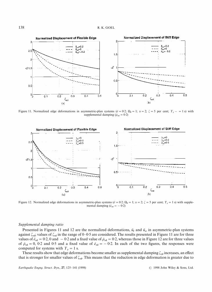
Figure 11. Normalized edge deformations in asymmetric-plan systems (eN"0·2; )h"1; a"2; f"5 per cent; ¹y!"1 s) with
supplemental damping (oN4$"0·2)
Figure 12. Normalized edge deformations in asymmetric-plan systems (eN"0·2; )h"1; a"2; f"5 per cent; ¹y"1 s) with supple-
mental damping (eN4$"!0·2)
Supplemental damping ratio
Presented in Figures 11 and 12 are the normalized deformations, uN&and uN
4, in asymmetric-plan systems
against f4$; values of f
4$in the range of 0—0·5 are considered. The results presented in Figure 11 are for three
values of eN4$"0·2, 0 and !0·2 and a fixed value of oN
4$"0·2, whereas those in Figure 12 are for three values
of oN4$"0, 0·2 and 0·5 and a fixed value of eN
4$"!0·2. In each of the two figures, the responses were
computed for systems with ¹y"1 s.
These results show that edge deformations become smaller as supplemental damping f4$
increases, an effectthat is stronger for smaller values of f
4$. This means that the reduction in edge deformation is greater due to
138 R. K. GOEL
Earthquake Engng. Struct. Dyn., 27, 125—141 (1998) ( 1998 John Wiley & Sons, Ltd.
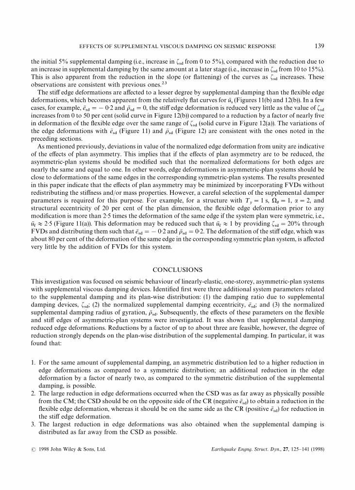
the initial 5% supplemental damping (i.e., increase in f4$
from 0 to 5%), compared with the reduction due toan increase in supplemental damping by the same amount at a later stage (i.e., increase in f
4$from 10 to 15%).
This is also apparent from the reduction in the slope (or flattening) of the curves as f4$
increases. Theseobservations are consistent with previous ones.23
The stiff edge deformations are affected to a lesser degree by supplemental damping than the flexible edgedeformations, which becomes apparent from the relatively flat curves for uN
4(Figures 11(b) and 12(b)). In a few
cases, for example, eN4$"!0·2 and oN
4$"0, the stiff edge deformation is reduced very little as the value of f
4$increases from 0 to 50 per cent (solid curve in Figure 12(b)) compared to a reduction by a factor of nearly fivein deformation of the flexible edge over the same range of f
4$(solid curve in Figure 12(a)). The variations of
the edge deformations with eN4$
(Figure 11) and oN4$
(Figure 12) are consistent with the ones noted in thepreceding sections.
As mentioned previously, deviations in value of the normalized edge deformation from unity are indicativeof the effects of plan asymmetry. This implies that if the effects of plan asymmetry are to be reduced, theasymmetric-plan systems should be modified such that the normalized deformations for both edges arenearly the same and equal to one. In other words, edge deformations in asymmetric-plan systems should beclose to deformations of the same edges in the corresponding symmetric-plan systems. The results presentedin this paper indicate that the effects of plan asymmetry may be minimized by incorporating FVDs withoutredistributing the stiffness and/or mass properties. However, a careful selection of the supplemental damperparameters is required for this purpose. For example, for a structure with ¹
y"1 s, )h"1, a"2, and
structural eccentricity of 20 per cent of the plan dimension, the flexible edge deformation prior to anymodification is more than 2·5 times the deformation of the same edge if the system plan were symmetric, i.e.,uN&+2·5 (Figure 11(a)). This deformation may be reduced such that uN
&+1 by providing f
4$"20% through
FVDs and distributing them such that eN4$"!0·2 and oN
4$"0·2. The deformation of the stiff edge, which was
about 80 per cent of the deformation of the same edge in the corresponding symmetric plan system, is affectedvery little by the addition of FVDs for this system.
CONCLUSIONS
This investigation was focused on seismic behaviour of linearly-elastic, one-storey, asymmetric-plan systemswith supplemental viscous damping devices. Identified first were three additional system parameters relatedto the supplemental damping and its plan-wise distribution: (1) the damping ratio due to supplementaldamping devices, f
4$; (2) the normalized supplemental damping eccentricity, eN
4$; and (3) the normalized
supplemental damping radius of gyration, oN4$. Subsequently, the effects of these parameters on the flexible
and stiff edges of asymmetric-plan systems were investigated. It was shown that supplemental dampingreduced edge deformations. Reductions by a factor of up to about three are feasible, however, the degree ofreduction strongly depends on the plan-wise distribution of the supplemental damping. In particular, it wasfound that:
1. For the same amount of supplemental damping, an asymmetric distribution led to a higher reduction inedge deformations as compared to a symmetric distribution; an additional reduction in the edgedeformation by a factor of nearly two, as compared to the symmetric distribution of the supplementaldamping, is possible.
2. The large reduction in edge deformations occurred when the CSD was as far away as physically possiblefrom the CM; the CSD should be on the opposite side of the CR (negative eN
4$) to obtain a reduction in the
flexible edge deformation, whereas it should be on the same side as the CR (positive eN4$) for reduction in
the stiff edge deformation.3. The largest reduction in edge deformations was also obtained when the supplemental damping is
distributed as far away from the CSD as possible.
EFFECTS OF SUPPLEMENTAL VISCOUS DAMPING ON SEISMIC RESPONSE 139
( 1998 John Wiley & Sons, Ltd. Earthquake Engng. Struct. Dyn., 27, 125—141 (1998)

4. Since eN4$
and oN4$
cannot physically take on the largest possible values simultaneously, a near optimalreduction may be obtained by using (a) as few dampers as possible in the direction under considerationand locating the outermost dampers at the two edges, and (b) dampers in the perpendicular direction.
5. The effects of the plan-wise distribution of supplemental damping were much more significant for stronglycoupled ()h"1) and torsionally-very-flexible ()h"0·5) asymmetric-plan systems. Furthermore, theseeffects were more pronounced for the flexible edge. Although edge deformations of torsionally-very-stiff()h"2) asymmetric-plan systems were reduced due to supplemental damping, they were essentiallyunaffected by its plan-wise distribution.
It has also been shown that edge deformations in asymmetric-plan systems can be reduced to levels equalto or smaller than those of the same edges in the corresponding symmetric-plan system by proper selection ofthe supplemental damping parameters alone, without redistributing the stiffness and/or mass properties ofthe system.
The findings in this paper are based on the responses of simple, one-storey systems computed for singleearthquake excitation. It would be useful to investigate the response behaviour of more complex systems,such as multi-storey buildings, and consider an ensemble of earthquakes in order to gain further confidencein these findings.
ACKNOWLEDGEMENTS
The author would like to thank Professors Anil Chopra and Andrei Reinhorn for their useful discussion onthe subject matter of this paper.
REFERENCES
1. R. Hejal and A. K. Chopra, ‘Earthquake response of torsionally-coupled buildings’, Report ºCB/EERC-87/20, EarthquakeEngineering Research Center, University of California, Berkeley, CA, 1987.
2. R. K. Goel and A. K. Chopra, ‘Inelastic seismic response of one-story, asymmetric-plan systems’, Report ºBC/EERC-90/14,Earthquake Engineering Research Center, University of California, Berkeley, CA, 1990.
3. A. Rutenberg, ‘Nonlinear response of asymmetric building structures and seismic codes: A state of the art review’, EuropeanEarthquake Engng. VI(2), 3—19 (1992).
4. International Association for Earthquake Engineering, Earthquake Resistant Regulations, A ¼orld ¸ist, 1992, Tokyo, 1992.5. I. D. Aiken and J. M. Kelly, ‘Earthquake simulator testing and analytical studies of two energy-absorbing systems for multistory
structures’, Report ºBC/EERC-90/03, Earthquake Engineering Research Center, University of California, Berkeley, CA, 1990.6. K. C. Chang, ‘Seismic behavior of steel frame with added viscoelastic dampers’, J. Struct. Engng. 121 (10), 1418—1426 (1995).7. K. C. Chang, T. T. Soong, M. L. Lai, E. J. Nielsen, ‘Viscoelastic dampers as energy dissipation devices for seismic applications’,
Earthquake Spectra 9 (3), 371—388 (1993).8. M. C. Constantinou and M. D. Symans, ‘Experimental and analytical investigation of seismic response of structures with
supplemental fluid viscous dampers’, Report No. NCEER-92-0032, National Center for Earthquake Engineering Research, Buffalo,NY, 1992.
9. Y. Fu, ‘Frame retrofit by using viscous and viscoelastic dampers’, CD-ROM Proc. 11th ¼orld Conf. on Earthquake Engineering,Paper No. 428, Elsevier Science Ltd., NY, 1996.
10. N. Gluck, A. M. Reinhorn, J. Gluck and R. Levy, ‘Design of supplemental dampers for control of structures’, J. Struct. Engng.122(12), 1394—1399 (1996).
11. R. D. Hanson, ‘Supplemental damping for improved seismic performance’, Earthquake Spectra 9(3), 319—334 (1993).12. R. D. Hanson, I. D. Aiken, D. K. Nims, P. J. Richter, and R. E. Bachman, ‘State-of-the-art and state-of-the-practice in seismic energy
dissipation’, Proc. Seminar and ¼orkshop on Base Isolation, Passive Energy Dissipation and Active Control, ATC 17-1, Vol. 2, AppliedTechnology Council, Palo Alto, CA, 1993, 449—472.
13. K. Kasai and J. A. Munsi, ‘Seismic response of viscoelastic frame with yielding members’, Proc. 5th National Conference onEarthquake Engineering, Vol. I, Earthquake Engineering Research Institute, Oakland, CA, 1994, 839—848.
14. N. Makris and M. C. Constantinou, ‘Spring-viscous damper systems for combined seismic and vibration isolation’, EarthquakeEngng. Struct. Dyn. 21(8), 649—664 (1992).
15. A. S. Pall, ‘Energy dissipation devices for aseismic design of buildings’, Proc. Seminar and ¼orkshop on Base Isolation and PassiveEnergy Dissipation, ATC-17, Applied Technology Council, Palo Alto, California, 1986, 223—232.
16. A. M. Reinhorn, C. Li and M. C. Constantinou, ‘Experimental and analytical investigation of seismic retrofit of structures withsupplemental damping: Part 1 — Fluid viscous damping devices’, Report No. NCEER-95-0001, National Center for EarthquakeEngineering Research, Buffalo, NY, 1995.
140 R. K. GOEL
Earthquake Engng. Struct. Dyn., 27, 125—141 (1998) ( 1998 John Wiley & Sons, Ltd.
17. P. Tsopelas, S. Okamoto, M. C. Constantinou, D. Ozaki and S. Fuji, ‘Experimental and analytical study of systems consisting ofsliding bearing, rubber restoring force devices, and fluid dampers’, Report No. NCEER-94-0002, National Center for EarthquakeEngineering Research, Buffalo, NY, 1994.
18. Rasmussen, E. ‘Dampers hold sway’, Civil Engng. 67(3), 40—43 (1997).19. A. Arista and R. Gomez, ‘Influence of energy dissipation devices on the torsional response of single-story structures’, Proc. Seminar
and ¼orkshop on Base Isolation and Passive Energy Dissipation, ACT-17-1, Applied Technology Council, Vol. 2, 1993, 651—662.20. L. Martin and O. A. Pekau, ‘Improved performance of friction damped asymmetric structures’, Proc. 5th Canadian Conf. on
Earthquake Engineering, Montreal, 1995, 927—934.21. O. A. Pekau and R. Guimond, ‘Controlling seismic response of eccentric structures by friction dampers’, Earthquake Engng. and
Struct. Dyn. 20(6), 505—521 (1991).22. Z. X. Li and Y. A. He, ‘Optimal damper control for 3-dimensional tall buildings under earthquake’, Proc. 10th ¼orld Conf. on
Earthquake Engineering, Vol. 7, 1992, 4159—4164.23. A. K. Chopra, Dynamics of Structures: ¹heory and Applications to Earthquake Engineering, Prentice-Hall, Upper Saddle River, NJ,
1995.
EFFECTS OF SUPPLEMENTAL VISCOUS DAMPING ON SEISMIC RESPONSE 141
( 1998 John Wiley & Sons, Ltd. Earthquake Engng. Struct. Dyn., 27, 125—141 (1998)