Effects of storm direction and duration on infiltrating planar flow with partial coverage
24
HYDROLOGICAL PROCESSES Hydrol. Process. 19, 969–992 (2005) Published online 16 September 2004 in Wiley InterScience (www.interscience.wiley.com). DOI: 10.1002/hyp.5554 Effects of storm direction and duration on infiltrating planar flow with partial coverage V. P. Singh* Department of Civil and Environmental Engineering, Louisiana State University, Baton Rouge, LA 70803-6405, USA Abstract: Using kinematic wave equations analytical solutions are derived for flow resulting from a storm moving either up or down an infiltrating plane but not fully covering it. By comparing the flow resulting from this storm with that from a stationary storm of the same duration the influence of storm duration, direction and velocity is investigated. It is found that the direction of storm movement, duration and velocity of storms, as well as basin infiltration, have a pronounced effect on the discharge hydrograph. Copyright 2004 John Wiley & Sons, Ltd. KEY WORDS Rainfall-runoff; discharge hydrograph; infiltrating plane; peak discharge; moving storm; overland flow; storm direction; time to peak INTRODUCTION Spatial and temporal distribution of rainfall is one of the main factors affecting watershed runoff, and this distribution is significantly affected by the direction and duration of storm movement. The direction of storm movement can be distinguished as upstream, downstream, across stream and angular to the stream. Maksimov (1964) recognized the importance of storm movement on surface runoff and showed that the rainstorm movement altered peak discharge. In a laboratory study Marcus (1964) showed the importance of the rainstorm movement to the time distribution of surface runoff. There have since been a number of investigations dealing with the influence of storm movement on watershed runoff. Singh (1997) has given a survey of such investigations. Roberts and Klingman (1970) found that the direction of storm movement might augment or reduce flood peaks and modify the hydrograph recession. Surkan (1974) observed that peak flow rates and average flow rates were most sensitive to changes in the direction and speed of the rainstorms. Niemczynowicz (1984a,b) determined the influence of storm direction, intensity, velocity and duration on the runoff hydrograph and peak discharge on a conceptual watershed and a real watershed in the City of Lund in Sweden. Yen and Chow (1968) undertook a laboratory investigation of surface runoff resulting from moving rainstorms. Sargent (1981, 1982) determined the effects of storm direction and speed on peak runoff, flood volume and hydrograph shape. Stephenson (1984) simulated runoff hydrographs from a storm travelling down a watershed. Jensen (1984) determined the influence of storm movement and its direction on the shape, peak, time to peak and other characteristics of the runoff hydrograph. Foroud et al. (1984) used a 50-year hypothetical moving rainstorm to quantify the effect of its speed and direction on the runoff hydrograph. Ngirane-Katashaya and Wheater (1985) analysed the effect of storm velocity on runoff hydrograph. Ogden et al. (1985) investigated the influence of storm movement on runoff. Singh (1998) examined the effect of the direction of storm movement on planar flow. Singh (2002) also examined the effect of storm movement on infiltrating planar flow with full area coverage. * Correspondence to: V. P. Singh, Department of Civil and Environmental Engineering, Louisiana State University, Baton Rouge, LA 70803-6405, USA. E-mail: [email protected] Received 1 July 2003 Copyright 2004 John Wiley & Sons, Ltd. Accepted 4 February 2004
Transcript of Effects of storm direction and duration on infiltrating planar flow with partial coverage
HYDROLOGICAL PROCESSESHydrol. Process. 19, 969–992 (2005)Published online 16 September 2004 in Wiley InterScience (www.interscience.wiley.com). DOI: 10.1002/hyp.5554
Effects of storm direction and duration on infiltratingplanar flow with partial coverage
V. P. Singh*Department of Civil and Environmental Engineering, Louisiana State University, Baton Rouge, LA 70803-6405, USA
Abstract:
Using kinematic wave equations analytical solutions are derived for flow resulting from a storm moving either up ordown an infiltrating plane but not fully covering it. By comparing the flow resulting from this storm with that from astationary storm of the same duration the influence of storm duration, direction and velocity is investigated. It is foundthat the direction of storm movement, duration and velocity of storms, as well as basin infiltration, have a pronouncedeffect on the discharge hydrograph. Copyright 2004 John Wiley & Sons, Ltd.
KEY WORDS Rainfall-runoff; discharge hydrograph; infiltrating plane; peak discharge; moving storm; overland flow;storm direction; time to peak
INTRODUCTION
Spatial and temporal distribution of rainfall is one of the main factors affecting watershed runoff, and thisdistribution is significantly affected by the direction and duration of storm movement. The direction ofstorm movement can be distinguished as upstream, downstream, across stream and angular to the stream.Maksimov (1964) recognized the importance of storm movement on surface runoff and showed that therainstorm movement altered peak discharge. In a laboratory study Marcus (1964) showed the importanceof the rainstorm movement to the time distribution of surface runoff. There have since been a number ofinvestigations dealing with the influence of storm movement on watershed runoff. Singh (1997) has givena survey of such investigations. Roberts and Klingman (1970) found that the direction of storm movementmight augment or reduce flood peaks and modify the hydrograph recession. Surkan (1974) observed that peakflow rates and average flow rates were most sensitive to changes in the direction and speed of the rainstorms.Niemczynowicz (1984a,b) determined the influence of storm direction, intensity, velocity and duration on therunoff hydrograph and peak discharge on a conceptual watershed and a real watershed in the City of Lundin Sweden.
Yen and Chow (1968) undertook a laboratory investigation of surface runoff resulting from movingrainstorms. Sargent (1981, 1982) determined the effects of storm direction and speed on peak runoff, floodvolume and hydrograph shape. Stephenson (1984) simulated runoff hydrographs from a storm travellingdown a watershed. Jensen (1984) determined the influence of storm movement and its direction on the shape,peak, time to peak and other characteristics of the runoff hydrograph. Foroud et al. (1984) used a 50-yearhypothetical moving rainstorm to quantify the effect of its speed and direction on the runoff hydrograph.Ngirane-Katashaya and Wheater (1985) analysed the effect of storm velocity on runoff hydrograph. Ogdenet al. (1985) investigated the influence of storm movement on runoff. Singh (1998) examined the effect ofthe direction of storm movement on planar flow. Singh (2002) also examined the effect of storm movementon infiltrating planar flow with full area coverage.
* Correspondence to: V. P. Singh, Department of Civil and Environmental Engineering, Louisiana State University, Baton Rouge, LA70803-6405, USA. E-mail: [email protected]
Received 1 July 2003Copyright 2004 John Wiley & Sons, Ltd. Accepted 4 February 2004
970 V. P. SINGH
Using kinematic wave theory this paper examines the influence on infiltrating planar flow of storms thatmay move up or down a plane but may not fully cover it. Partial coverage of the plane by the storm meansthat the storm duration is limited and not large enough to cover the entire plane. It is well known that when arainstorm occurs, it may occur only over a portion of the watershed. This is true whether the storm is movingor stationary. Furthermore, it is also true that watersheds are infiltrating. An analytical treatment of the effectof storm movement occurring over only a portion of the infiltrating watershed does not appear to have beenreported in the literature. Most of the studies cited above have either been numerical or empirical. Analyticalsolutions provide considerable insight into the relationship between storm dynamics and flow dynamics. Bycomparing the flow resulting from a moving storm with that from a stationary storm of the same duration itinvestigates the influence of storm direction on flow hydrograph. It is recognized that a plan is not an adequaterepresentation of a natural watershed but it is a basic geometric element of a network used for representingthe watershed (Singh, 1996). Thus it is desirable to understand the effect on the discharge hydrograph ofstorms covering only a portion of infiltrating watersheds. It is hoped that the results of this investigation canbe incorporated into a complete watershed model.
FLOW OVER AN INFILTRATING PLANE: DOWNSTREAM STORM DIRECTION
We consider a plane of length L and width unity. The plane infiltrates at the rate of f, which is assumedconstant in space and time. The storm does not occur for sufficiently long duration and hence does not coverthe entire plane. Let the storm cover the plane length of aL where a, 0 � a � 1, is a fraction, Thus, there isa region �I � a� L not covered by the storm. In other words, the region 0 � x � aL is covered by the stormand the region aL � x � L is not covered by the storm. We first examine the case when the storm directionis downstream.
The governing equations for flow over an infiltrating plane can be expressed as
∂h
∂tC ∂Q
∂xD q�x, �� � f�x, �� �1�
Q D ˛hn �2�
where� D t � x
VS�3�
defines the time for which the storm has occurred at the position x and time t, and Vs is the storm velocity. Thestorm travel path is defined as t D x/Vs. For a storm duration T, the duration of storm rainfall at any positionx is T � x/Vs, indicating the varying duration throughout the plane length. For purposes of simplicity andderiving analytical solutions, both q and f are assumed constant in space and time, i.e. q�x, t� D q D constant,and f�x, t� D f D constant.
The initial and boundary conditions can be expressed as
h�x, t D x
VS� D 0 �4�
h�0, t� D 0 �5�
Equations (1) and (2) can be coupled to yield
∂h
∂tC n˛hn�1 ∂h
∂xD q � f �6�
Copyright 2004 John Wiley & Sons, Ltd. Hydrol. Process. 19, 969–992 (2005)
EFFECT OF STORM DIRECTION AND DURATION ON INFILTRATING FLOW 971
Equation (6) can be solved, subject to Equations (4) and (5), using the method of characteristics (see Singh(1996) for a complete treatment). Accordingly, the characteristic form of this equation is
dh
dtD q � f �7�
dx
dtD n˛hn�1 �8�
To solve Equations (7) and (8) it is more convenient to take x as the characteristic parameter instead of t.These equations therefore become
dh
dxD q � f
n˛hn�1 �9�
dt
dxD 1
n˛hn�1 �10�
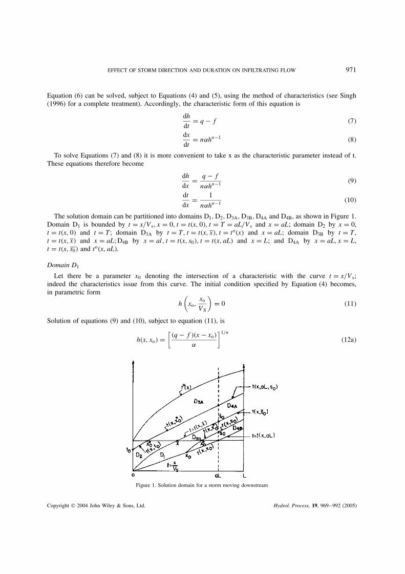
The solution domain can be partitioned into domains D1, D2, D3A, D3B, D4A and D4B, as shown in Figure 1.Domain D1 is bounded by t D x/Vs, x D 0, t D t�x, 0�, t D T D aL/Vs and x D aL; domain D2 by x D 0,t D t�x, 0� and t D T; domain D3A by t D T, t D t�x, x�, t D to�x� and x D aL; domain D3B by t D T,t D t�x, x� and x D aL; D4B by x D al, t D t�x, s0�, t D t�x, aL� and x D L; and D4A by x D aL, x D L,t D t�x, s0� and to�x, aL�.
Domain D1
Let there be a parameter x0 denoting the intersection of a characteristic with the curve t D x/Vs;indeed the characteristics issue from this curve. The initial condition specified by Equation (4) becomes,in parametric form
h
(xo,
xo
VS
)D 0 �11�
Solution of equations (9) and (10), subject to equation (11), is
h�x, xo� D[
�q � f��x � xo�
˛
]1/n
�12a�
Figure 1. Solution domain for a storm moving downstream
Copyright 2004 John Wiley & Sons, Ltd. Hydrol. Process. 19, 969–992 (2005)
972 V. P. SINGH
t�x, xo� D xo
VSC �q � f�� �n�1�
n
(x � xo
˛
)1/n
�12b�
Equations (12a) and (12b) constitute the parametric solution in domain D1. Eliminating x0 between equations(12a) and (12b), the flow depth, as a function of x and t, can be expressed as
t D x
Vs� ˛hn
�q � f�VsC h
q � f�13a�
and flow discharge asQ D ˛hn D �q � f�Vs[hVs C �q � f�x � t] �13b�
Domain D2
Let there be a parameter t0 denoting the intersection of a characteristic with the t axis �x D 0�, 0 � t0 � T.The initial condition given by Equation (5) takes the parametric form of
h�0, t0� D 0 �14�
Solution of Equations (9) and (10), subject to Equation (14), follows
h D(
q � f
˛x
)1/n
�15a�
t D to C �q � f�� �n�1�n
( x
˛
)1/n�15b�
Equations (15a) and (15b) constitute the parametric solution in domain D2. The flow depth, as a function ofx and t, can be expressed as
h�x, t� D[
�q � f�x
˛
]1/n
�16a�
and flow discharge asQ�x, t� D �q � f�x �16b�
Domain D3A
Let there be a parameter xŁo, 0 � xŁ
o � x, denoting the intersection of a characteristic with t D T. Thecharacteristics issuing from 0 � xŁ
o � x are elongations of the characteristics of domain D2. The initialcondition therefore is
h�xŁo, T� D ho �17�
where ho is given by the solution of domain D2
ho D(
q � f
˛xŁo
)1/n
�18�
Equation (9), with q D 0, becomesdh
dxD � f
n˛hn�1 �19�
Solution of Equations (19) and (10) follows
h D[(
q � f
˛xŁo
)� f
˛�x � xŁ
o�
]1/n
�20�
Copyright 2004 John Wiley & Sons, Ltd. Hydrol. Process. 19, 969–992 (2005)
EFFECT OF STORM DIRECTION AND DURATION ON INFILTRATING FLOW 973
Equations (20) and (21) constitute the parametric solution in domain D3A. By eliminating xŁ0 between them
the flow depth as well as discharge as functions of x and t can be expressed
t D aL
VSC 1
f
[q � f
˛xŁo
]1/n
� 1
f
[q � f
˛xŁo � f
˛�x � xŁ
o�
]1/n
�21�
Domain D3B
In this domain x � xŁo � aL. The characteristics issuing from this line are elongations of the characteristics
of domain D1. The initial condition therefore is given by Equation (17), where h0 is obtained from the solutionof domain D1 as
ho D(
�q � f��xŁo � xo�
˛
)1/n
�22�
where the parameter x0 and xŁ0 are related by Equation (12b), with x replaced by xŁ
0 , as
xŁo D xo C ˛�q � f��n�1�
(aL � xo
VS
)n
�23�
or
T D aL
VsD x0
VsC �q � f���n�1�/n
(xŁ0 � x0
˛
)1/n
�24�
Solution of Equations (19) and (10), subject to Equation (22), follows
h�x, xoŁ� D
[q � f
˛�xo
Ł � xo� � f
˛�x � xo
Ł�
]1/n
�25a�
t�x, xoŁ� D aL
VSC 1
f
[q � f
˛�xo
Ł � xo�
]1/n
� 1
f
[q � f
˛�xo
Ł � xo� � f
˛�x � xo
Ł�
]1/n
�25b�
Determination of free boundary
Along the free boundary, (to�x�, h D 0). Therefore from Equation (20), one obtains
xoŁ D f
qx �26�
Substitution of Equation (26) in Equation (21) yields
to�x� D aL
VSC f� �n�1�
n
(1
˛
)n (q � f
qx
)1/n
�27�
Equation (27) expresses the time history of the drying edge or of zero depth. This is the boundary of zerodepth that was not known in advance.
Domain D4B
Let there be a characteristic parameter s0 denoting the intersection of a characteristic with the line x D aL.The characteristics issue from the time segment T � s0 � s0. Parameter s0 is the intersection of the linex D aL and t D t�x, x�. The characteristics issuing in this domain are elongations of the characteristics ofdomain D3B. Therefore the boundary condition in this domain is defined from Equation (25a) as
h�s0, x0Ł� D h0 D
[q � f
˛�x0
Ł � x0� � f
˛�aL � x0
Ł�
]1/n
�28�
Copyright 2004 John Wiley & Sons, Ltd. Hydrol. Process. 19, 969–992 (2005)
974 V. P. SINGH
where s0 and x0Ł are connected through Equation (25b) as
s0 D aL
VsC 1
f
[q � f
˛�x0
Ł � x0�
]1/n
� 1
f
[�q � f�
˛�x0
Ł � x0� � f
˛�aL � x0�
]1/n
�29�
in which x0 and x0Ł are related by Equation (23).
The solution of Equations (19) and (10), subject to Equation (28), is
h�x, s0� D[h0
n � f
˛�x � aL�
]1/n
�30�
t�x, s0� D s0 C 1
f
{h0 �
[h0
n � f
˛�x � aL�
]1/n}
�31�
Equations (30) and (31) constitute the parametric solution in domain D4B. These equations can be combinedto yield
h�x, t� D h0 � f�t � s0� �32a�
Equation (32a) shows that the flow depth is a linear function of time and decreases in time as a result ofcontinuing infiltration. Likewise, the flow discharge is
Q�x, t� D ˛[h0 � f�t � s0�]n �32b�
Domain D4A
Let there be a characteristic parameter s0 denoting the intersection of a characteristic with the line x D aL.The characteristics issue from the time segment s0 ½ s0. Parameter S0 is the intersection of the line x D aLand t D t�x, x�. The characteristics issuing in this domain are elongations of the characteristics of domainD3A. Therefore the boundary condition in this domain is defined from Equation (20) as
h�xŁ0, s0� D h0 D
[q � f
˛xŁ0 � f
˛�aL � xŁ
0�
]1/n
�33a�
where xŁ0 and s0 are related by Equation (21) as
s0 D aL
VsC 1
f
[q � f
˛xŁ0
]1/n
� 1
f
[q � f
˛xŁ0 � f
˛�aL � xŁ
0�
]1/n
�33b�
The solution of Equations (19) and (10), subject to Equation (33a), is
h�x, s0� D[h0
n � f
˛�x � aL�
]1/n
�34a�
t�x, s0� D s0 C 1
f
{h0 �
[h0
n � f
˛�x � aL�
]1/n}
�34b�
Equations (34a) and (34b) constitute the parametric solution in domain D4A. These equations can be combinedto yield flow depth as
h�x, t� D h0 � f�t � s0� �35a�
and flow discharge asQ�x, t� D [h0 � f�t � s0�]
n �35b�
Copyright 2004 John Wiley & Sons, Ltd. Hydrol. Process. 19, 969–992 (2005)
EFFECT OF STORM DIRECTION AND DURATION ON INFILTRATING FLOW 975
This shows that the flow depth is a linear function of time and decreases in time as a result of continuinginfiltration.
FLOW OVER AN INFILTRATING PLANE: UPSTREAM STORM DIRECTION
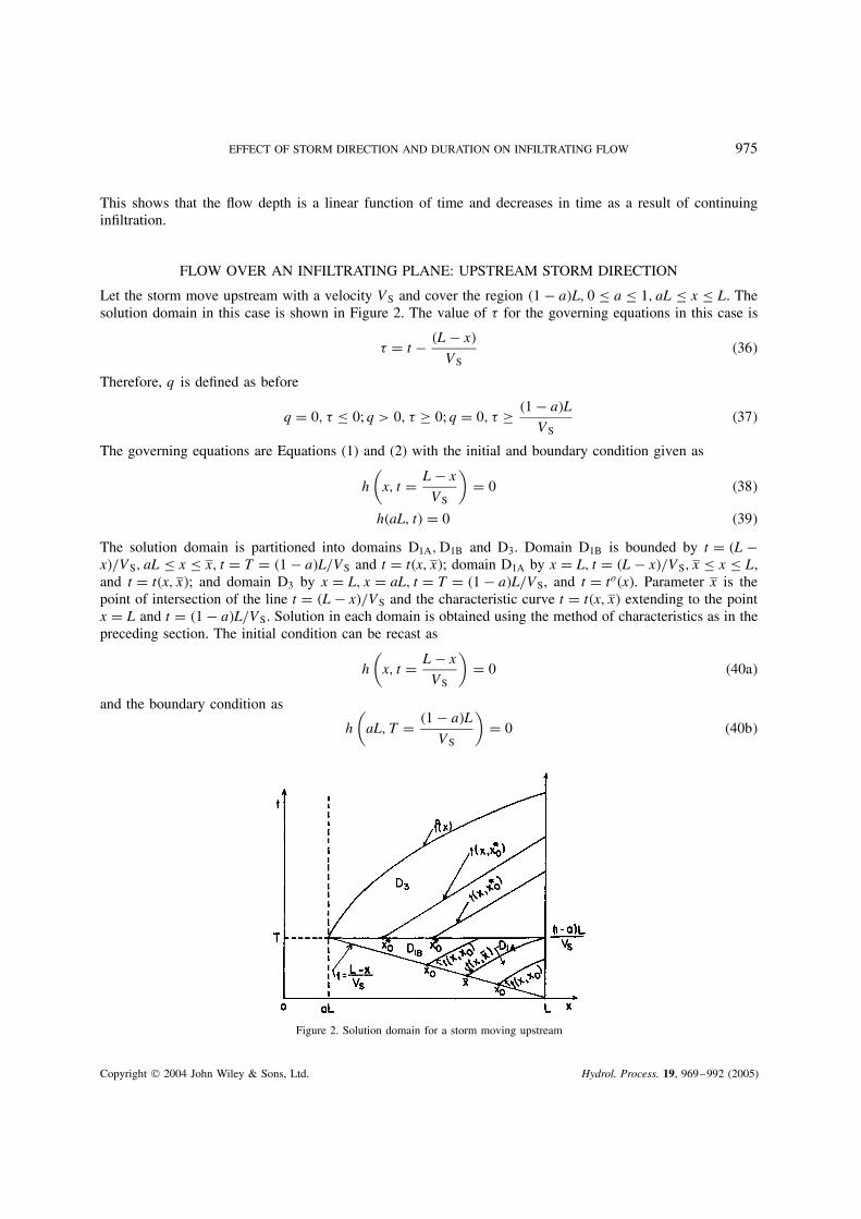
Let the storm move upstream with a velocity VS and cover the region �1 � a�L, 0 � a � 1, aL � x � L. Thesolution domain in this case is shown in Figure 2. The value of � for the governing equations in this case is
� D t � �L � x�
VS�36�
Therefore, q is defined as before
q D 0, � � 0; q > 0, � ½ 0; q D 0, � ½ �1 � a�L
VS�37�
The governing equations are Equations (1) and (2) with the initial and boundary condition given as
h
(x, t D L � x
VS
)D 0 �38�
h�aL, t� D 0 �39�
The solution domain is partitioned into domains D1A, D1B and D3. Domain D1B is bounded by t D �L �x�/VS, aL � x � x, t D T D �1 � a�L/VS and t D t�x, x�; domain D1A by x D L, t D �L � x�/VS, x � x � L,and t D t�x, x�; and domain D3 by x D L, x D aL, t D T D �1 � a�L/VS, and t D to�x�. Parameter x is thepoint of intersection of the line t D �L � x�/VS and the characteristic curve t D t�x, x� extending to the pointx D L and t D �1 � a�L/VS. Solution in each domain is obtained using the method of characteristics as in thepreceding section. The initial condition can be recast as
h
(x, t D L � x
VS
)D 0 �40a�
and the boundary condition as
h
(aL, T D �1 � a�L
VS
)D 0 �40b�
Figure 2. Solution domain for a storm moving upstream
Copyright 2004 John Wiley & Sons, Ltd. Hydrol. Process. 19, 969–992 (2005)
976 V. P. SINGH
The governing equations are Equations (9) and (10), which have to be solved in each domain subject toEquations (40a) and (40b).
Domain D1A
Let there be a characteristic parameter x0, x � x0 � L, denoting the intersection of a characteristic with theline t D �L � x�/Vs. Indeed the characteristics issue from this line and are denoted as t�x, x0�. The initialcondition given by Equation (40a) is expressed in parametric form as
h
(x0,
L � x0
VS
)D 0 �41�
The solution of Equations (9) and (10), subject to Equation (41), follows
h�x, xo� D(
q � f
˛�x � xo�
)1/n
�42a�
t�x, xo� D L � xo
VSC
(q � f
˛
)� �n�1�n
(x � xo
˛
)1/n
�42b�
The value of x is obtained by Equation (42b) as
aL
VS� x
VSC �q � f�� �n�1�
n
(L � x
˛
)1/n
D �1 � a�L
Vs�42c�
Equations (42a) and (42b) constitute the parametric solution in domain D1A. By eliminating parameter x0
between them the flow depth can be expressed as a function of x and t.
Domain D1B
The solution is the same as in D1 for aL � xo � x.
Domain D3
Let there be a parameter xŁ0, aL � xŁ
0 � L, denoting the intersection of a characteristic with the linet D T D �1 � a�L/Vs. The characteristics issue from the line t D T. In this case rainfall has ceased to occur.Therefore, Equation (9) takes the form
dh
dxD �f
˛
1
nhn�1 �43�
The initial condition is given by Equation (42a) with x replaced by xŁ0
ho D(
q � f
˛�xŁ
o � xo�
)1/n
�44�
The solution of Equations (10) and (43), subject to Equation (44), follows
h�x, xŁo� D
[q � f
˛�xŁ
o � xo� � f
˛�x � xŁ
o�
]1/n
�45�
t�x, xŁo� D �1 � a�L
VSC 1
f
[q � f
˛�xŁ
o � xo�
]1/n
� 1
f
[q � f
˛�xŁ
o � xo� � f
˛�x � xŁ
o�
]1/n
�46�
Copyright 2004 John Wiley & Sons, Ltd. Hydrol. Process. 19, 969–992 (2005)

EFFECT OF STORM DIRECTION AND DURATION ON INFILTRATING FLOW 977
Equations (45) and (46) constitute the parametric solution in domain D3. The connection between x0 and xŁ0
is given by Equation (42b) with x replaced by xŁ0 and t by T or �1 � a�L/Vs as
T D �1 � a�L
VSD L � x0
VSC �q � f�
˛
� n�1n
(xŁo � x0
˛
) 1n
�47�
Determination of Free boundary
From Equation (45)
xŁo D f
qx C q � f
qxo �48�
Substitution of Equation (48) in Equation (46) produces an expression of the free boundary
to�x� D �1 � a�L
VSC f� �n�1�
n
(q � f
˛q
)1/n
�x � xo�1/n �49�
APPLICATION
The effect of the direction and duration of storm movement on infiltrating planar flow was analysed byconsidering both moving and stationary storms. The storm velocities were taken as 1Ð5, 3, 5 and 10 times thenormalizing velocity of flow. The planar area covered by a storm was varied as 25, 50 and 75 of the totalarea. For each velocity, the duration of the storm would be fixed for a fixed areal coverage. In each case thehydrograph at the downstream end of the plane would be a partially equilibrium one.
For purposes of comparison and ease of graphical portrayal it is more convenient to use dimensionlesssolutions. To that end the following normalizing quantities were defined:
U D normalizing flow velocity D ˛Hn�10 �50�
H0 D normalizing flow depth
L D normalizing distance D plane length
D D normalizing time D time to equilibrium D time of concentration �tc� D L/U �51�
Q0 D normalizing discharge D ˛Hn0 D H0U D qmaxL �52�
qmax D maximum excess rainfall intensity D H0/D D UH0
LD Q0
L�53�
The normalizing quantities were in accord with a stationary storm. Thus, the dimensionless quantities can bedefined as
xŁ D x
L, tŁ D t
DD tU
L, hŁ D h
H0, QŁ D Q
Q0D Q
Lqmax, qŁ D q
qmax,
�Ł D t
D� xU
VsL, VŁ
s D Vs
U, TŁ D T
D, fŁ D f
qmax�54�
Using these quantities dimensional solutions were rendered dimensionless. Appendix A contains dimension-less solutions.
Stationary storms covering upstream portion
Stationary storms were allowed to cover only a portion �a > 0� of the infiltrating planar watershed beginningwith the upstream side. The value of a was taken as a D 0Ð25, 0Ð5 and 0Ð75. For each storm covering a fixed
Copyright 2004 John Wiley & Sons, Ltd. Hydrol. Process. 19, 969–992 (2005)
978 V. P. SINGH
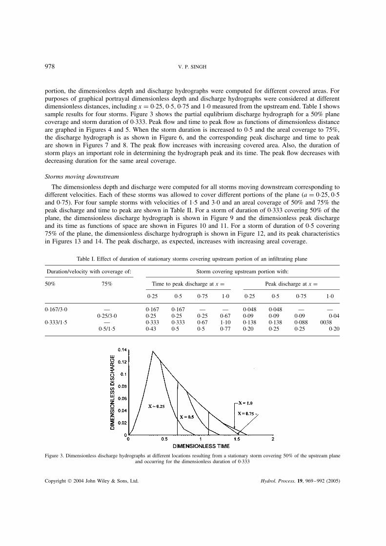
portion, the dimensionless depth and discharge hydrographs were computed for different covered areas. Forpurposes of graphical portrayal dimensionless depth and discharge hydrographs were considered at differentdimensionless distances, including x D 0Ð25, 0Ð5, 0Ð75 and 1Ð0 measured from the upstream end. Table I showssample results for four storms. Figure 3 shows the partial equlibrium discharge hydrograph for a 50% planecoverage and storm duration of 0Ð333. Peak flow and time to peak flow as functions of dimensionless distanceare graphed in Figures 4 and 5. When the storm duration is increased to 0Ð5 and the areal coverage to 75%,the discharge hydrograph is as shown in Figure 6, and the corresponding peak discharge and time to peakare shown in Figures 7 and 8. The peak flow increases with increasing covered area. Also, the duration ofstorm plays an important role in determining the hydrograph peak and its time. The peak flow decreases withdecreasing duration for the same areal coverage.
Storms moving downstream
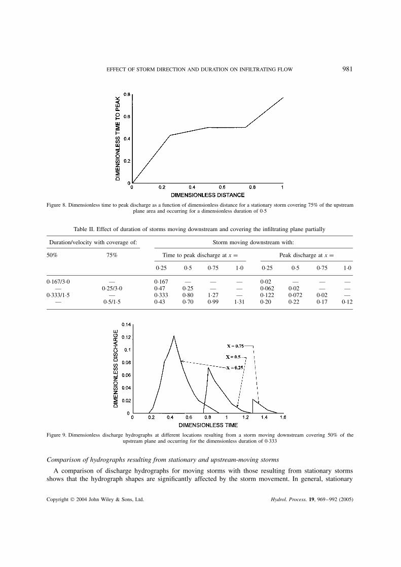
The dimensionless depth and discharge were computed for all storms moving downstream corresponding todifferent velocities. Each of these storms was allowed to cover different portions of the plane (a D 0Ð25, 0Ð5and 0Ð75). For four sample storms with velocities of 1Ð5 and 3Ð0 and an areal coverage of 50% and 75% thepeak discharge and time to peak are shown in Table II. For a storm of duration of 0Ð333 covering 50% of theplane, the dimensionless discharge hydrograph is shown in Figure 9 and the dimensionless peak dischargeand its time as functions of space are shown in Figures 10 and 11. For a storm of duration of 0Ð5 covering75% of the plane, the dimensionless discharge hydrograph is shown in Figure 12, and its peak characteristicsin Figures 13 and 14. The peak discharge, as expected, increases with increasing areal coverage.
Table I. Effect of duration of stationary storms covering upstream portion of an infiltrating plane
Duration/velocity with coverage of: Storm covering upstream portion with:
50% 75% Time to peak discharge at x D Peak discharge at x D0Ð25 0Ð5 0Ð75 1Ð0 0Ð25 0Ð5 0Ð75 1Ð0
0Ð167/3Ð0 — 0Ð167 0Ð167 — — 0Ð048 0Ð048 — —0Ð25/3Ð0 0Ð25 0Ð25 0Ð25 0Ð67 0Ð09 0Ð09 0Ð09 0Ð04
0Ð333/1Ð5 — 0Ð333 0Ð333 0Ð67 1Ð10 0Ð138 0Ð138 0Ð088 00380Ð5/1Ð5 0Ð43 0Ð5 0Ð5 0Ð77 0Ð20 0Ð25 0Ð25 0Ð20
Figure 3. Dimensionless discharge hydrographs at different locations resulting from a stationary storm covering 50% of the upstream planeand occurring for the dimensionless duration of 0Ð333
Copyright 2004 John Wiley & Sons, Ltd. Hydrol. Process. 19, 969–992 (2005)

EFFECT OF STORM DIRECTION AND DURATION ON INFILTRATING FLOW 979
Figure 4. Dimensionless peak discharge as a function of dimensionless distance for a stationary storm of dimensionless duration of 0Ð333and upstream areal coverage of 50%
Figure 5. Dimensionless peak time as a function of space for a stationary storm of dimensionless duration of 0Ð333 and upstream arealcoverage of 50%
Comparison of hydrographs resulting from stationary and downstream-moving storms
A comparison of hydrographs corresponding to moving storms of different velocities with those resultingfrom stationary storms covering the same areas shows that the hydrograph shape changes significantly formoving storms. This is especially true with the rising part and the peak portion. Also the timings are changed.As storm velocity rises, the hydrograph tends to approach the one resulting from stationary storms. In general,for the same areal coverage the stationary storms produce higher peak discharge than do storms movingdownstream, but the reverse is true for the time to peak.
Stationary storms covering downstream portion
Stationary storms were allowed to cover only a portion of the planar area beginning with the downstreamside. The values of �1 � a� were taken as 0Ð25, 0Ð5 and 0Ð75. For each storm covering different plane areas,dimensionless depth and discharge hydrographs were computed. For a storm duration of 0Ð333 and 50% of thearea covered, Figure 15 shows dimensionless discharge and peak flow and time to peak flow as functions ofdimensionless distance are graphed in Figure 16 and 17, respectively. When the covered area was increasedto 75% and the storm duration to 0Ð25, the resulting discharge hydrograph is shown in Figure 18, and the
Copyright 2004 John Wiley & Sons, Ltd. Hydrol. Process. 19, 969–992 (2005)

980 V. P. SINGH
Figure 6. Dimensionless discharge hydrograph resulting from a stationary storm covering 75% of the upstream plane and occurring for adimensionless duration of 0Ð5
Figure 7. Dimensionless peak discharge as a function of dimensionless distance for a stationary storm covering 75% of the upstream planearea and occurring for a dimensionless duration of 0Ð5
peak and its time in Figures 19 and 20. For four sample storms the peak discharge and its time are shownin Table III. It is observed that the peak discharge increases with increasing areal coverage as well as withincreasing storm duration. This also applies to the time to peak discharge.
Storms moving upstream
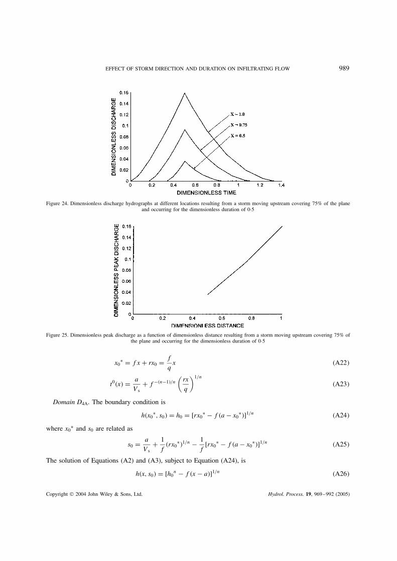
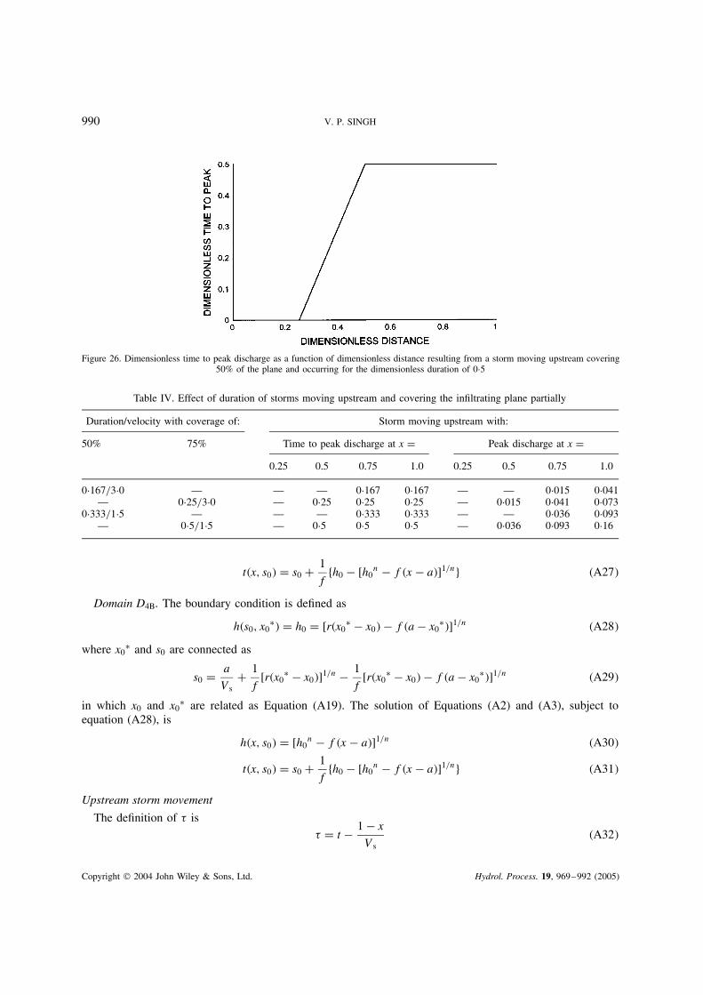
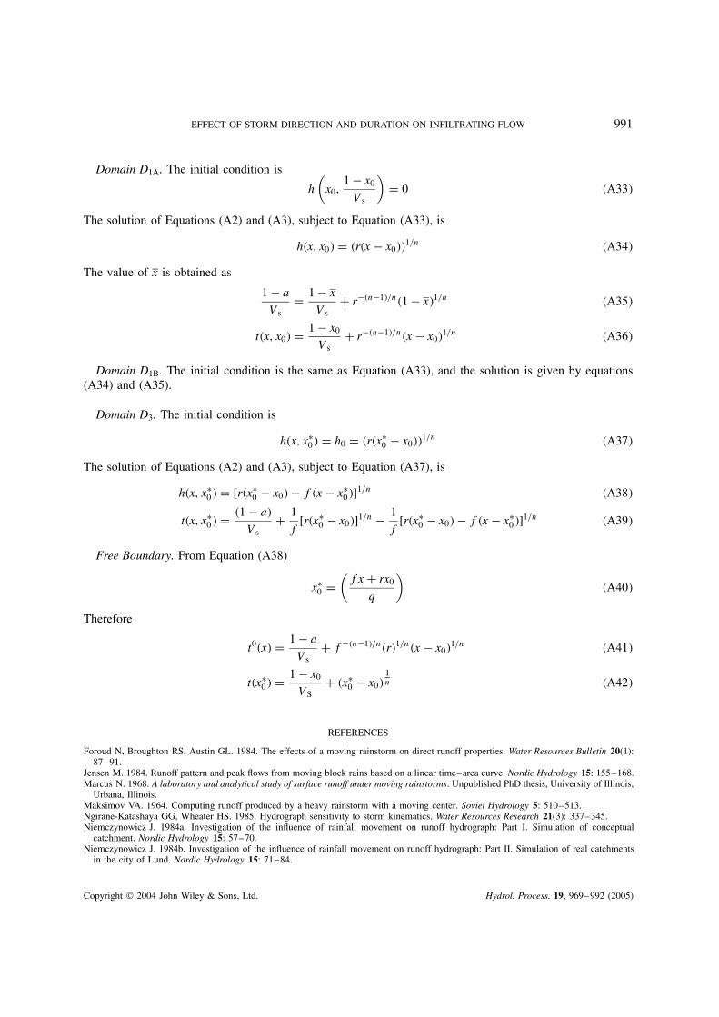
The dimensionless depth and discharge hydrographs were computed for all storms moving upstreamcorresponding to different velocities and different covered areas. For a storm of duration 0Ð333 covering50% of the plane, the discharge hydrograph is shown in Figure 21 and the corresponding peak characteristicsare shown in Figures 22 and 23. For another storm of duration 0Ð5 covering 75% of the plane, the dischargehydrograph is shown in Figure 24 and the dimensionless peak discharge and its time as functions of space aredepicted in Figures 25 and 26. The peak characteristics for four sample storms are shown in Table IV. It isfound that the peak discharge increases with increasing areal coverage and storm duration. This also appliesto the time to peak discharge.
Copyright 2004 John Wiley & Sons, Ltd. Hydrol. Process. 19, 969–992 (2005)
EFFECT OF STORM DIRECTION AND DURATION ON INFILTRATING FLOW 981
Figure 8. Dimensionless time to peak discharge as a function of dimensionless distance for a stationary storm covering 75% of the upstreamplane area and occurring for a dimensionless duration of 0Ð5
Table II. Effect of duration of storms moving downstream and covering the infiltrating plane partially
Duration/velocity with coverage of: Storm moving downstream with:
50% 75% Time to peak discharge at x D Peak discharge at x D0Ð25 0Ð5 0Ð75 1Ð0 0Ð25 0Ð5 0Ð75 1Ð0
0Ð167/3Ð0 — 0Ð167 — — — 0Ð02 — — —— 0Ð25/3Ð0 0Ð47 0Ð25 — — 0Ð062 0Ð02 — —
0Ð333/1Ð5 — 0Ð333 0Ð80 1Ð27 — 0Ð122 0Ð072 0Ð02 —— 0Ð5/1Ð5 0Ð43 0Ð70 0Ð99 1Ð31 0Ð20 0Ð22 0Ð17 0Ð12
Figure 9. Dimensionless discharge hydrographs at different locations resulting from a storm moving downstream covering 50% of theupstream plane and occurring for the dimensionless duration of 0Ð333
Comparison of hydrographs resulting from stationary and upstream-moving storms
A comparison of discharge hydrographs for moving storms with those resulting from stationary stormsshows that the hydrograph shapes are significantly affected by the storm movement. In general, stationary
Copyright 2004 John Wiley & Sons, Ltd. Hydrol. Process. 19, 969–992 (2005)

982 V. P. SINGH
Figure 10. Dimensionless peak discharge as a function of dimensionless distance resulting from a storm moving downstream covering 50%of the upstream plane and occurring for the dimensionless duration of 0Ð333
Figure 11. Dimensionless time to peak discharge as a function of dimensionless distance resulting from a storm moving downstream covering50% of the upstream plane and occurring for the dimensionless duration of 0Ð333
storms produce a higher peak and lower or equal time to peak than do storms moving upstream.
Comparison of hydrographs resulting from downstream-moving and upstream-moving storms
A comparison of hydrographs shows that for the same areal coverage and storm duration, the storms movingupstream produce higher peak discharge than do storms moving downstream. The reverse is true for the timeto peak flow. This is because infiltration has higher opportunity time to occur for storms moving downstreamthan for storms moving upstream.
CONCLUSIONS
The following conclusions can be drawn from this study.
1. The hydrograph shape is significantly affected by the storm movement.2. The timing of the discharge delivery at the outlet is influenced by the direction of storm movement.
Copyright 2004 John Wiley & Sons, Ltd. Hydrol. Process. 19, 969–992 (2005)
EFFECT OF STORM DIRECTION AND DURATION ON INFILTRATING FLOW 983
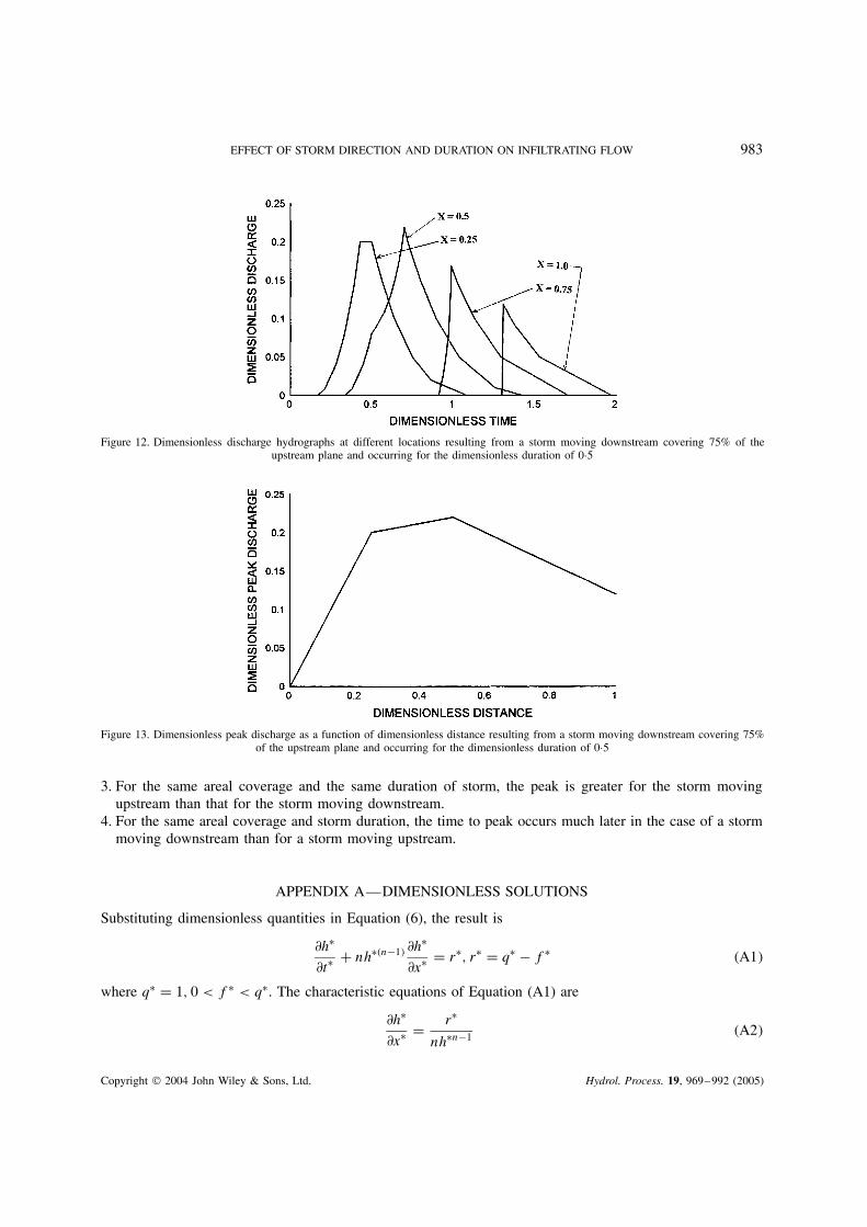
Figure 12. Dimensionless discharge hydrographs at different locations resulting from a storm moving downstream covering 75% of theupstream plane and occurring for the dimensionless duration of 0Ð5
Figure 13. Dimensionless peak discharge as a function of dimensionless distance resulting from a storm moving downstream covering 75%of the upstream plane and occurring for the dimensionless duration of 0Ð5
3. For the same areal coverage and the same duration of storm, the peak is greater for the storm movingupstream than that for the storm moving downstream.
4. For the same areal coverage and storm duration, the time to peak occurs much later in the case of a stormmoving downstream than for a storm moving upstream.
APPENDIX A—DIMENSIONLESS SOLUTIONS
Substituting dimensionless quantities in Equation (6), the result is
∂hŁ
∂tŁ C nhŁ�n�1� ∂hŁ
∂xŁ D rŁ, rŁ D qŁ � fŁ �A1�
where qŁ D 1, 0 < fŁ < qŁ. The characteristic equations of Equation (A1) are
∂hŁ
∂xŁ D rŁ
nhŁn�1 �A2�
Copyright 2004 John Wiley & Sons, Ltd. Hydrol. Process. 19, 969–992 (2005)
984 V. P. SINGH
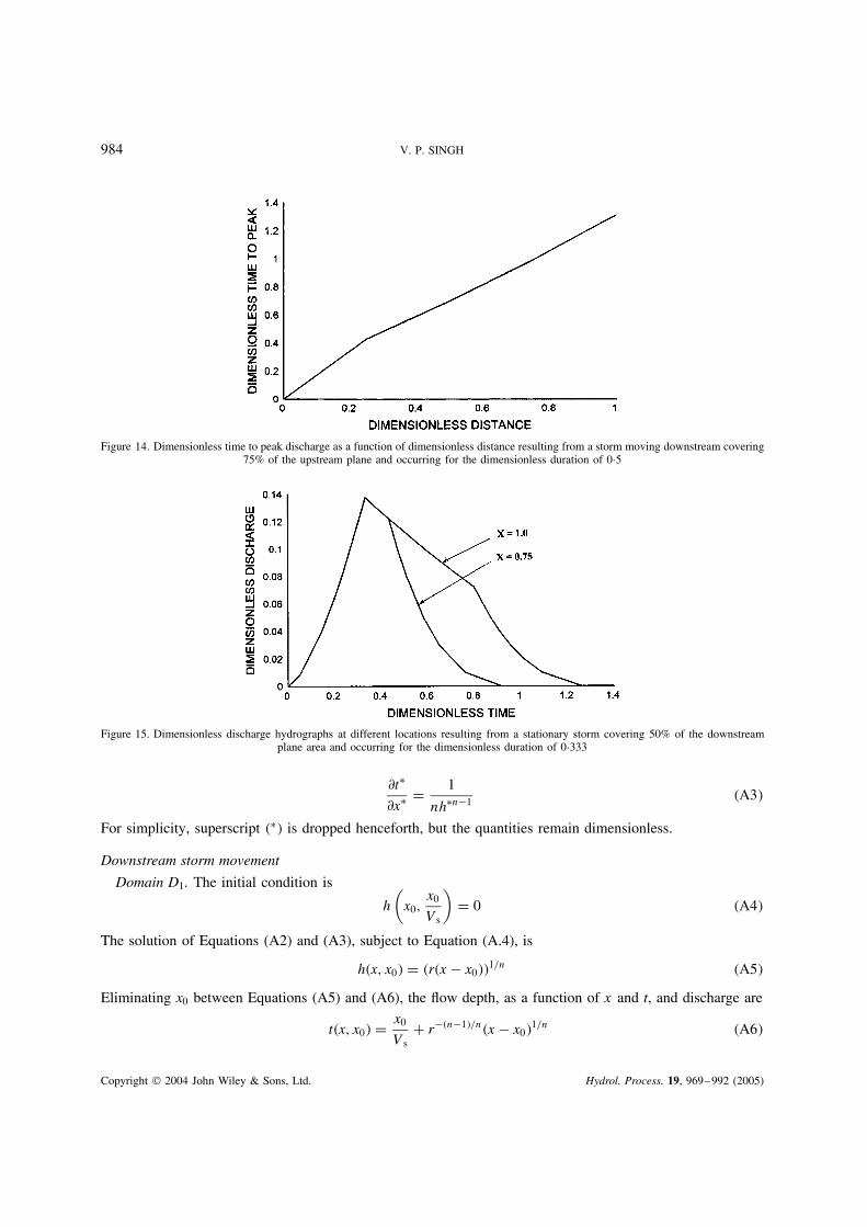
Figure 14. Dimensionless time to peak discharge as a function of dimensionless distance resulting from a storm moving downstream covering75% of the upstream plane and occurring for the dimensionless duration of 0Ð5
Figure 15. Dimensionless discharge hydrographs at different locations resulting from a stationary storm covering 50% of the downstreamplane area and occurring for the dimensionless duration of 0Ð333
∂tŁ
∂xŁ D 1
nhŁn�1 �A3�
For simplicity, superscript �Ł� is dropped henceforth, but the quantities remain dimensionless.
Downstream storm movement
Domain D1. The initial condition is
h
(x0,
x0
Vs
)D 0 �A4�
The solution of Equations (A2) and (A3), subject to Equation (A.4), is
h�x, x0� D �r�x � x0��1/n �A5�
Eliminating x0 between Equations (A5) and (A6), the flow depth, as a function of x and t, and discharge are
t�x, x0� D x0
VsC r��n�1�/n�x � x0�
1/n �A6�
Copyright 2004 John Wiley & Sons, Ltd. Hydrol. Process. 19, 969–992 (2005)
EFFECT OF STORM DIRECTION AND DURATION ON INFILTRATING FLOW 985
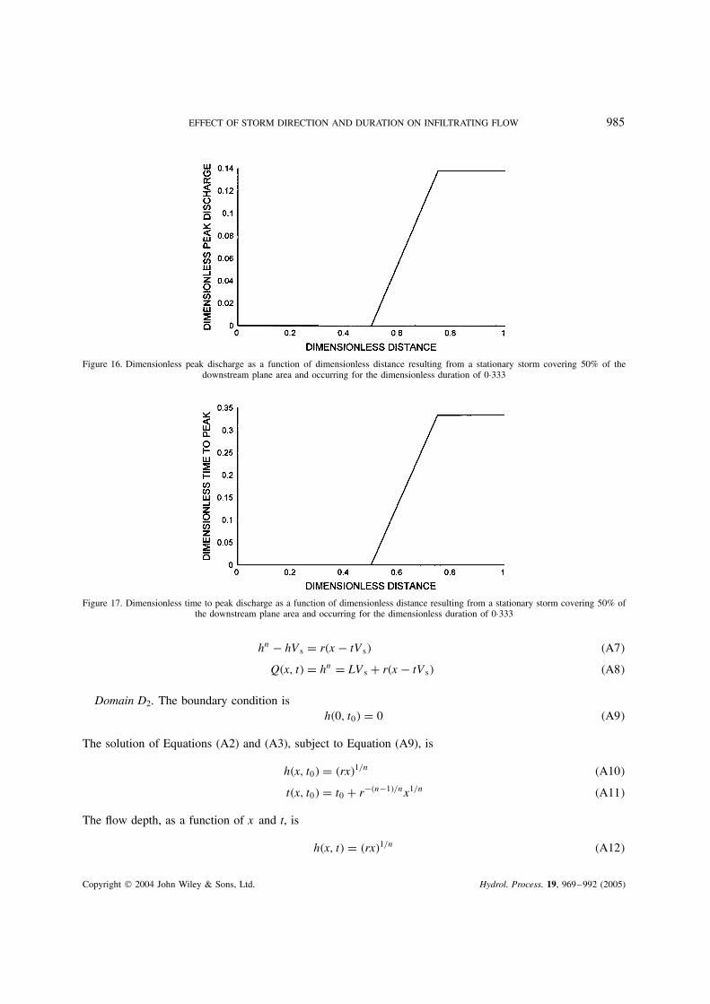
Figure 16. Dimensionless peak discharge as a function of dimensionless distance resulting from a stationary storm covering 50% of thedownstream plane area and occurring for the dimensionless duration of 0Ð333
Figure 17. Dimensionless time to peak discharge as a function of dimensionless distance resulting from a stationary storm covering 50% ofthe downstream plane area and occurring for the dimensionless duration of 0Ð333
hn � hVs D r�x � tVs� �A7�
Q�x, t� D hn D LVs C r�x � tVs� �A8�
Domain D2. The boundary condition ish�0, t0� D 0 �A9�
The solution of Equations (A2) and (A3), subject to Equation (A9), is
h�x, t0� D �rx�1/n �A10�
t�x, t0� D t0 C r��n�1�/nx1/n �A11�
The flow depth, as a function of x and t, is
h�x, t� D �rx�1/n �A12�
Copyright 2004 John Wiley & Sons, Ltd. Hydrol. Process. 19, 969–992 (2005)

986 V. P. SINGH
Figure 18. Dimensionless discharge hydrographs at different locations resulting from a stationary storm covering 75% of the downstreamplane area and occurring for the dimensionless duration of 0Ð25
Figure 19. Dimensionless peak discharge as a function of dimensionless distance resulting from a stationary storm covering 75% of thedownstream plane area and occurring for the dimensionless duration of 0Ð25
and flow discharge, as a function of x and t, is
Q D rx �A13�
Domain D3A. The initial condition is given by the solution of domain D2
h�x0Ł, T� D h0 �A14�
where h0 ish0 D �rx0
Ł�1/n �A15�
Solutions of Equations (A2) and (A3), subject to Equation (A14), is
h�x, x0Ł� D [rx0
Ł � f�x � x0Ł�]1/n �A16�
Copyright 2004 John Wiley & Sons, Ltd. Hydrol. Process. 19, 969–992 (2005)
EFFECT OF STORM DIRECTION AND DURATION ON INFILTRATING FLOW 987
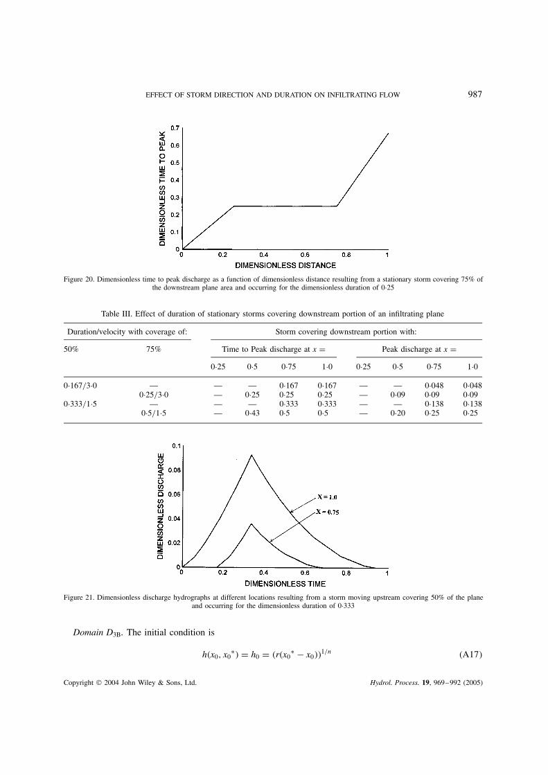
Figure 20. Dimensionless time to peak discharge as a function of dimensionless distance resulting from a stationary storm covering 75% ofthe downstream plane area and occurring for the dimensionless duration of 0Ð25
Table III. Effect of duration of stationary storms covering downstream portion of an infiltrating plane
Duration/velocity with coverage of: Storm covering downstream portion with:
50% 75% Time to Peak discharge at x D Peak discharge at x D0Ð25 0Ð5 0Ð75 1Ð0 0Ð25 0Ð5 0Ð75 1Ð0
0Ð167/3Ð0 — — — 0Ð167 0Ð167 — — 0Ð048 0Ð0480Ð25/3Ð0 — 0Ð25 0Ð25 0Ð25 — 0Ð09 0Ð09 0Ð09
0Ð333/1Ð5 — — — 0Ð333 0Ð333 — — 0Ð138 0Ð1380Ð5/1Ð5 — 0Ð43 0Ð5 0Ð5 — 0Ð20 0Ð25 0Ð25
Figure 21. Dimensionless discharge hydrographs at different locations resulting from a storm moving upstream covering 50% of the planeand occurring for the dimensionless duration of 0Ð333
Domain D3B. The initial condition is
h�x0, x0Ł� D h0 D �r�x0
Ł � x0��1/n �A17�
Copyright 2004 John Wiley & Sons, Ltd. Hydrol. Process. 19, 969–992 (2005)
988 V. P. SINGH
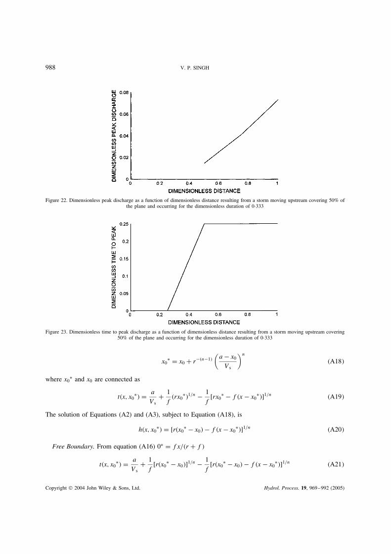
Figure 22. Dimensionless peak discharge as a function of dimensionless distance resulting from a storm moving upstream covering 50% ofthe plane and occurring for the dimensionless duration of 0Ð333
Figure 23. Dimensionless time to peak discharge as a function of dimensionless distance resulting from a storm moving upstream covering50% of the plane and occurring for the dimensionless duration of 0Ð333
x0Ł D x0 C r��n�1�
(a � x0
Vs
)n
�A18�
where x0Ł and x0 are connected as
t�x, x0Ł� D a
VsC 1
f�rx0
Ł�1/n � 1
f[rx0
Ł � f�x � x0Ł�]1/n �A19�
The solution of Equations (A2) and (A3), subject to Equation (A18), is
h�x, x0Ł� D [r�x0
Ł � x0� � f�x � x0Ł�]1/n �A20�
Free Boundary. From equation (A16) 0Ł D fx/�r C f�
t�x, x0Ł� D a
VsC 1
f[r�x0
Ł � x0�]1/n � 1
f[r�x0
Ł � x0� � f�x � x0Ł�]1/n �A21�
Copyright 2004 John Wiley & Sons, Ltd. Hydrol. Process. 19, 969–992 (2005)
EFFECT OF STORM DIRECTION AND DURATION ON INFILTRATING FLOW 989
Figure 24. Dimensionless discharge hydrographs at different locations resulting from a storm moving upstream covering 75% of the planeand occurring for the dimensionless duration of 0Ð5
Figure 25. Dimensionless peak discharge as a function of dimensionless distance resulting from a storm moving upstream covering 75% ofthe plane and occurring for the dimensionless duration of 0Ð5
x0Ł D fx C rx0 D f
qx �A22�
t0�x� D a
VsC f��n�1�/n
(rx
q
)1/n
�A23�
Domain D4A. The boundary condition is
h�x0Ł, s0� D h0 D [rx0
Ł � f�a � x0Ł�]1/n �A24�
where x0Ł and s0 are related as
s0 D a
VsC 1
f�rx0
Ł�1/n � 1
f[rx0
Ł � f�a � x0Ł�]1/n �A25�
The solution of Equations (A2) and (A3), subject to Equation (A24), is
h�x, s0� D [h0n � f�x � a�]1/n �A26�
Copyright 2004 John Wiley & Sons, Ltd. Hydrol. Process. 19, 969–992 (2005)
990 V. P. SINGH
Figure 26. Dimensionless time to peak discharge as a function of dimensionless distance resulting from a storm moving upstream covering50% of the plane and occurring for the dimensionless duration of 0Ð5
Table IV. Effect of duration of storms moving upstream and covering the infiltrating plane partially
Duration/velocity with coverage of: Storm moving upstream with:
50% 75% Time to peak discharge at x D Peak discharge at x D0.25 0.5 0.75 1.0 0.25 0.5 0.75 1.0
0Ð167/3Ð0 — — — 0Ð167 0Ð167 — — 0Ð015 0Ð041— 0Ð25/3Ð0 — 0Ð25 0Ð25 0Ð25 — 0Ð015 0Ð041 0Ð073
0Ð333/1Ð5 — — — 0Ð333 0Ð333 — — 0Ð036 0Ð093— 0Ð5/1Ð5 — 0Ð5 0Ð5 0Ð5 — 0Ð036 0Ð093 0Ð16
t�x, s0� D s0 C 1
ffh0 � [h0
n � f�x � a�]1/ng �A27�
Domain D4B. The boundary condition is defined as
h�s0, x0Ł� D h0 D [r�x0
Ł � x0� � f�a � x0Ł�]1/n �A28�
where x0Ł and s0 are connected as
s0 D a
VsC 1
f[r�x0
Ł � x0�]1/n � 1
f[r�x0
Ł � x0� � f�a � x0Ł�]1/n �A29�
in which x0 and x0Ł are related as Equation (A19). The solution of Equations (A2) and (A3), subject to
equation (A28), is
h�x, s0� D [h0n � f�x � a�]1/n �A30�
t�x, s0� D s0 C 1
ffh0 � [h0
n � f�x � a�]1/ng �A31�
Upstream storm movement
The definition of � is� D t � 1 � x
Vs�A32�
Copyright 2004 John Wiley & Sons, Ltd. Hydrol. Process. 19, 969–992 (2005)
EFFECT OF STORM DIRECTION AND DURATION ON INFILTRATING FLOW 991
Domain D1A. The initial condition is
h
(x0,
1 � x0
Vs
)D 0 �A33�
The solution of Equations (A2) and (A3), subject to Equation (A33), is
h�x, x0� D �r�x � x0��1/n �A34�
The value of x is obtained as
1 � a
VsD 1 � x
VsC r��n�1�/n�1 � x�1/n �A35�
t�x, x0� D 1 � x0
VsC r��n�1�/n�x � x0�
1/n �A36�
Domain D1B. The initial condition is the same as Equation (A33), and the solution is given by equations(A34) and (A35).
Domain D3. The initial condition is
h�x, xŁ0� D h0 D �r�xŁ
0 � x0��1/n �A37�
The solution of Equations (A2) and (A3), subject to Equation (A37), is
h�x, xŁ0� D [r�xŁ
0 � x0� � f�x � xŁ0�]1/n �A38�
t�x, xŁ0� D �1 � a�
VsC 1
f[r�xŁ
0 � x0�]1/n � 1
f[r�xŁ
0 � x0� � f�x � xŁ0�]1/n �A39�
Free Boundary. From Equation (A38)
xŁ0 D
(fx C rx0
q
)�A40�
Therefore
t0�x� D 1 � a
VsC f��n�1�/n�r�1/n�x � x0�
1/n �A41�
t�xŁ0� D 1 � x0
VSC �xŁ
0 � x0�1n �A42�
REFERENCES
Foroud N, Broughton RS, Austin GL. 1984. The effects of a moving rainstorm on direct runoff properties. Water Resources Bulletin 20(1):87–91.
Jensen M. 1984. Runoff pattern and peak flows from moving block rains based on a linear time–area curve. Nordic Hydrology 15: 155–168.Marcus N. 1968. A laboratory and analytical study of surface runoff under moving rainstorms. Unpublished PhD thesis, University of Illinois,
Urbana, Illinois.Maksimov VA. 1964. Computing runoff produced by a heavy rainstorm with a moving center. Soviet Hydrology 5: 510–513.Ngirane-Katashaya GG, Wheater HS. 1985. Hydrograph sensitivity to storm kinematics. Water Resources Research 21(3): 337–345.Niemczynowicz J. 1984a. Investigation of the influence of rainfall movement on runoff hydrograph: Part I. Simulation of conceptual
catchment. Nordic Hydrology 15: 57–70.Niemczynowicz J. 1984b. Investigation of the influence of rainfall movement on runoff hydrograph: Part II. Simulation of real catchments
in the city of Lund. Nordic Hydrology 15: 71–84.
Copyright 2004 John Wiley & Sons, Ltd. Hydrol. Process. 19, 969–992 (2005)
992 V. P. SINGH
Ogden FL, Richardson JR, Julien PY. 1995. Similarity in catchment response: 2. Moving rainstorms. Water Resources Research 31(6):1543–1547.
Roberts MC, and Klingman PC. 1970. The influence of landform and precipitation parameters on flood hydrographs. Journal of Hydrology11: 393–411.
Sargent DM. 1981. An investigation into the effects of storm movement on the design of urban drainage systems: Part 1. The Public HealthEngineer 9: 201–207.
Sargent DM. 1982. An investigation into the effects of storm movement on the design of urban drainage systems: Part 2. Probability analysis.The Public Health Engineer 10(2): 111–117.
Singh VP. 1996. Kinematic Wave Modeling in Water Resources: Surface Water Hydrology . Wiley: New York; 1399 pp.Singh VP. 1997. Effect of spatial and temporal variability in rainfall and watershed characteristics on streamflow hydrograph. Hydrological
Processes 11: 1649–1669.Singh VP. 1998. Effect of the direction of storm movement on planar flow. Hydrological Processes 12: 147–170.Singh VP. 2002. Effect of the duration of storm movement on infiltrating planar flow with full areal coverage. Hydrological Processes 16:
1479–1511.Stephenson D. 1984. Kinematic study of effects of storm dynamics on runoff hydrographs. Water SA 10(4): 189–196.Surkan AJ. 1974. Simulation of storm velocity effects of flow from distributed channel network. Water Resources Research 10(6): 1149–1160.Yen BC, Chow VT. 1968. A Study of Surface Runoff due to Moving Rainstorms . Hydraulic Engineering Series No. 17, Department of Civil
Engineering, University of Illinois: Urbana, IL; 112 pp.
Copyright 2004 John Wiley & Sons, Ltd. Hydrol. Process. 19, 969–992 (2005)