Effects of orthodontic mini-implant position in the dragon ...
9
ORIGINAL ARTICLE 191 a Assistant Professor, g Professor, Division of Orthodontics, Department of Dentistry, School of Medicine, Ewha Womans University. b Visiting Scholar, Division of Orthodontics, Department of Dentis- try, University of Nebraska Medical Center. c Former Student, Department of Orthodontics, Graduate School of Clinical Dentistry, Ewha Womans University. d Associate Professor, Division of Orthodontics, Department of Dentistry, College of Medicine, The Catholic University of Korea, St. Mary’s Hospital. e Associate Professor, Department of Orthodontics, University of Ulsan College of Medicine, Asan Medical Center. f Associate Professor, School of Mechanical and Automobile Engineering, Kunsan National University. Corresponding author: Youn-Sic Chun. Division of Orthodontics, Department of Dentistry, School of Medicine, Ewha Womans University, 911-1 Mok-dong, Yang- cheon-gu, Seoul 158-710, Korea. +82 2 2650 5114; e-mail, [email protected]. Received August 27, 2010; Last Revision October 22, 2010; Accepted October 25, 2010. DOI:10.4041/kjod.2011.41.3.191 Effects of orthodontic mini-implant position in the dragon helix appliance on tooth displacement and stress distribution: a three-dimensional finite element analysis Min-Ji Kim, DDS, MSD, PhD, a Sun-Hyung Park, DDS, MSD, PhD, b Hyeon-Seong Kim, DDS, MSD, c Sung-Seo Mo, DDS, MSD, PhD, d Sang-Jin Sung, DDS, MSD, PhD, e Gang-Won Jang, MSD, PhD, f Youn-Sic Chun, DDS, MSD, PhD g Objective: The purpose of this study was to investigate the stress distribution on the orthodontic mini-im- plant (OMI) surface and periodontal ligament of the maxillary first and second molars as well as the tooth displacement according to the OMI position in the dragon helix appliance during scissors-bite correction. Methods: OMIs were placed at two maxillary positions, between the first and the second premolars (group 1) and between the second premolar and the first molar (group 2). The stress distribution area (SDA) was analyzed by three-dimensional finite element analysis. Results: The maximal SDA of the OMI did not differ between the groups. It was located at the cervical area and palatal root apex of the maxillary first molar in groups 1 and 2, respectively, indicating less tipping in group 2. The minimal SDA was located at the root and furcation area of the maxillary second molar in groups 1 and 2, respectively, indicating greater palatal crown displacement in group 2. Conclusions: Placement of the OMI between the maxillary second premolar and the maxillary first molar to serve as an indirect anchor in the dragon helix appliance mini- mizes anchorage loss while maximizing the effect on scissors-bite correction. (Korean J Orthod 2011; 41(3):191-199) Key words: Orthodontic mini-implant, FEM INTRODUCTION Scissors-bite is a condition in which the maxillary teeth are abnormally positioned in the buccal direction (or lingual direction for the mandibular teeth) to result in total crossbite. 1,2 Correcting this condition is a prob- lematic issue because the treatment methods used so far have limitations. For example, a sound third molar is required for use after extracting the maxillary second molar, 3 and the application of a magnetic force with corticotomy requires a surgical procedure and its result depends on the patient's condition. 4 Further, the modi- fied transpalatal arch causes loss of anchorage and can be used only in mild cases because of limited space for lingual attachment on the affected second molar. 5
Transcript of Effects of orthodontic mini-implant position in the dragon ...

ORIGINAL ARTICLE
191
aAssistant Professor, gProfessor, Division of Orthodontics,
Department of Dentistry, School of Medicine, Ewha Womans
University.bVisiting Scholar, Division of Orthodontics, Department of Dentis-
try, University of Nebraska Medical Center.cFormer Student, Department of Orthodontics, Graduate School of
Clinical Dentistry, Ewha Womans University.dAssociate Professor, Division of Orthodontics, Department of
Dentistry, College of Medicine, The Catholic University of Korea,
St. Mary’s Hospital.eAssociate Professor, Department of Orthodontics, University of
Ulsan College of Medicine, Asan Medical Center.fAssociate Professor, School of Mechanical and Automobile
Engineering, Kunsan National University.
Corresponding author: Youn-Sic Chun.
Division of Orthodontics, Department of Dentistry, School of
Medicine, Ewha Womans University, 911-1 Mok-dong, Yang-
cheon-gu, Seoul 158-710, Korea.
+82 2 2650 5114; e-mail, [email protected].
Received August 27, 2010; Last Revision October 22, 2010;
Accepted October 25, 2010.
DOI:10.4041/kjod.2011.41.3.191
Effects of orthodontic mini-implant position in the dragon helix
appliance on tooth displacement and stress distribution:
a three-dimensional finite element analysis
Min-Ji Kim, DDS, MSD, PhD,a Sun-Hyung Park, DDS, MSD, PhD,
b Hyeon-Seong Kim, DDS, MSD,
c
Sung-Seo Mo, DDS, MSD, PhD,d Sang-Jin Sung, DDS, MSD, PhD,e Gang-Won Jang, MSD, PhD,f
Youn-Sic Chun, DDS, MSD, PhDg
Objective: The purpose of this study was to investigate the stress distribution on the orthodontic mini-im-plant (OMI) surface and periodontal ligament of the maxillary first and second molars as well as the tooth displacement according to the OMI position in the dragon helix appliance during scissors-bite correction. Methods: OMIs were placed at two maxillary positions, between the first and the second premolars (group 1) and between the second premolar and the first molar (group 2). The stress distribution area (SDA) was analyzed by three-dimensional finite element analysis. Results: The maximal SDA of the OMI did not differ between the groups. It was located at the cervical area and palatal root apex of the maxillary first molar in groups 1 and 2, respectively, indicating less tipping in group 2. The minimal SDA was located at the root and furcation area of the maxillary second molar in groups 1 and 2, respectively, indicating greater palatal crown displacement in group 2. Conclusions: Placement of the OMI between the maxillary second premolar and the maxillary first molar to serve as an indirect anchor in the dragon helix appliance mini-mizes anchorage loss while maximizing the effect on scissors-bite correction. (Korean J Orthod 2011; 41(3):191-199)
Key words: Orthodontic mini-implant, FEM
INTRODUCTION
Scissors-bite is a condition in which the maxillary
teeth are abnormally positioned in the buccal direction
(or lingual direction for the mandibular teeth) to result
in total crossbite.1,2
Correcting this condition is a prob-
lematic issue because the treatment methods used so
far have limitations. For example, a sound third molar
is required for use after extracting the maxillary second
molar,3 and the application of a magnetic force with
corticotomy requires a surgical procedure and its result
depends on the patient's condition.4 Further, the modi-
fied transpalatal arch causes loss of anchorage and can
be used only in mild cases because of limited space
for lingual attachment on the affected second molar.5

Kim MJ, Park SH, Kim HS, Mo SS, Sung SJ, Jang GW, Chun YS 대치교정지 41권 3호, 2011년
192
Node numbers of
the OMI
Element numbers of
the OMI
Total node
numbers
Total element
numbers
OMI 2,392 8,571 87,476 404,560
Maxillary first molar 6,494 28,196
PDL of maxillary first molar 4,616 4,540
Maxillary second molar 4,722 20,195
PDL of maxillary second molar 3,288 3,255
OMI, Orthodontic mini-implant; PDL, periodontal ligament.
Table 2. Elements and number of nodes in the finite element analysis
Element type Young’s modulus (g/mm2) Poisson’s ratio
Teeth Solid 45 2E6 0.3
Periodontal ligament Solid 45 5.0 0.3
Alveolar bone Solid 45 2E5 0.3
Splinting wire (0.018" × 0.025") Beam 4 2E7 0.3
Dragon helix (0.016" × 0.025") Beam 4 1.1E7 0.3
Table 1. Element type, Young’s modulus, and Poisson’s ratio of the material compounds of the finite element models
Fig 1. Clinical application of the dragon helix appliancefor tipping and intruding the maxillary second molar.
The molar intrusion arch and cross-arch elastic also
have disadvantages such as altered occlusion.6,7 Recent-
ly, the orthodontic mini-implant (OMI) was introduced
for intrusion and correction of the maxillary second
molar, but more than one implant is needed for direct
bony anchorage and it is yet difficult to control torque
and rotation.8,9
The dragon helix appliance combined with OMI-
based indirect skeletal anchorage has been introduced
recently to correct scissors-bite.1 This system consists
of a helix with two arms, about 5 mm in length, made
by 0.016" × 0.022" stainless steel wire set at an angle
of 110o (Fig 1). One arm is attached to the occlusal
surface of the maxillary second molar, while the other
is attached to the buccal side of the maxillary first
molar. This device produces about 200 - 250 g of or-
thodontic force without causing occlusal interference.
The anchor tooth is connected to the OMI by a rigid
wire such as 0.019" × 0.025" stainless steel, which
provides strong indirect skeletal anchorage during the
treatment of scissors-bite.10-13
However, considering that the OMI is the most im-
portant part of the appliance for anchorage, its position
might have some effect on the efficiency of anchorage.
The purpose of this study was to investigate the stress
distribution on the OMI surface and periodontal liga-
ment (PDL) of the maxillary first and second molars
as well as the tooth displacement according to the
Vol. 41, No. 3, 2011. Korean J Orthod Effects of the position of mini-implant
193
OMI position in the dragon helix appliance during
scissors-bite correction.
MATERIAL AND METHODS
A typodont model of the maxillary left quadrant
with scissors-bite at the second molar, which was ex-
truded and buccally inclined, was fabricated. The mod-
el was three-dimensionally (3D) scanned and 3D com-
puter-aided design (CAD) data were acquired by using
Computer-Aided Three-Dimensional Interactive Appli-
cation Version 5 (CATIA V5; Dassault Systèmes,
Vélizy-Villacoublay, France). The PDL attached to the
root surfaces was fabricated from Hyper Mesh 8.0
(Altair Engineering, Troy, MI, USA). The Young’s
modulus and Poisson’s ratio values of the PDL, alveo-
lar bone, connecting wire, and dragon helix were as-
sumed from an isotropic homogeneous linear elastic
model (Table 1).
CATIA V5 was also used to create a finite element
model of an OMI. Table 2 shows the elements and
number of nodes. The dimensions of the OMI were 9
mm length, 5.7 mm spiral part, 0.6 mm pitch, and 5.7o
taper angle. The dragon helix appliance was shaped in-
to a spring of 2 mm diameter and 11 turns with 0.016"
× 0.022" stainless steel wire. It was placed at the
crown of the maxillary first molar and intrusively over-
corrected second molar. Activation of the dragon helix
appliance was simulated by fixing the distal arm to the
affected second molar using the Constraint Equation of
Ansys (ANSYS, Canonsburg, PA, USA). The appli-
ance was assumed to produce about 200 - 250 g of
force.1
The OMI and first molar were connected with
0.018" × 0.025" stainless steel wire for indirect anchor-
age, and the first and second molars were connected
with the dragon helix appliance. Two groups were ana-
lyzed on the basis of the OMI position. In group 1, the
OMI was positioned between the first and the second
premolars, and in group 2, it was placed between the
second premolar and the first molar. The stress dis-
tribution of the OMI and PDL of the first and second
molars as well as the tooth displacement were ana-
lyzed by finite element analysis with Ansys version 11
and HP workstation XW 6400 (Zeon 1.6 Ghz, *2
CPU, RAM 4G).
The von Mises stress on the first and second molars,
and the OMI was determined to evaluate the stress
distribution. Displacement graphs of the axes of the
OMI (from the center of the head to the screw end tip)
and thefirst and second molars (from the palatal cusp
tip to the palatal root apex) were used to observe the
amount and pattern of displacement.
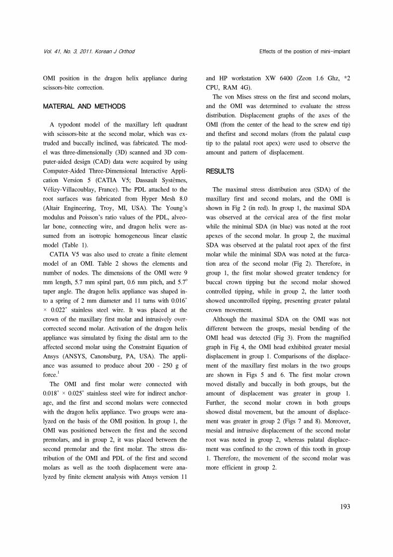
RESULTS
The maximal stress distribution area (SDA) of the
maxillary first and second molars, and the OMI is
shown in Fig 2 (in red). In group 1, the maximal SDA
was observed at the cervical area of the first molar
while the minimal SDA (in blue) was noted at the root
apexes of the second molar. In group 2, the maximal
SDA was observed at the palatal root apex of the first
molar while the minimal SDA was noted at the furca-
tion area of the second molar (Fig 2). Therefore, in
group 1, the first molar showed greater tendency for
buccal crown tipping but the second molar showed
controlled tipping, while in group 2, the latter tooth
showed uncontrolled tipping, presenting greater palatal
crown movement.
Although the maximal SDA on the OMI was not
different between the groups, mesial bending of the
OMI head was detected (Fig 3). From the magnified
graph in Fig 4, the OMI head exhibited greater mesial
displacement in group 1. Comparisons of the displace-
ment of the maxillary first molars in the two groups
are shown in Figs 5 and 6. The first molar crown
moved distally and buccally in both groups, but the
amount of displacement was greater in group 1.
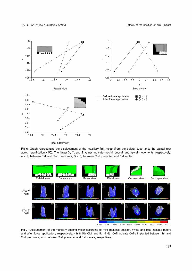
Further, the second molar crown in both groups
showed distal movement, but the amount of displace-
ment was greater in group 2 (Figs 7 and 8). Moreover,
mesial and intrusive displacement of the second molar
root was noted in group 2, whereas palatal displace-
ment was confined to the crown of this tooth in group
1. Therefore, the movement of the second molar was
more efficient in group 2.

Kim MJ, Park SH, Kim HS, Mo SS, Sung SJ, Jang GW, Chun YS 대치교정지 41권 3호, 2011년
194
Fig 2. The stress distribution on the periodontal ligament of the maxillary first and second molars as well as the orthodonticmini-implant (OMI) according to the OMI position. The color change from blue to red indicates increase in force. 4th &5th OMI and 5th & 6th OMI indicate OMIs implanted between 1st and 2nd premolars, and between 2nd premolar and1st molars, respectively.

Vol. 41, No. 3, 2011. Korean J Orthod Effects of the position of mini-implant
195
Fig 3. Displacement of the orthodontic mini-implant according to its position (magnification, × 500). White and blueindicate before and after the force application, respectively. 4th & 5th OMI and 5th & 6th OMI indicate OMIs implantedbetween 1st and 2nd premolars, and between 2nd premolar and 1st molars, respectively.
DISCUSSION
OMIs have been widely used in orthodontics since
their introduction as an effective anchor.9,14,15 Their
easy application, in expensiveness, and possibility of
immediate loading are well-recognized advantages.
When an orthodontic force is applied directly to the
OMI, it enables direct anchorage. This method of di-
rect anchorage is more popular than indirect anchorage,
which is considered to cause interference in osseo-
intergration.16 However, direct anchorage with the OMI
has disadvantages such as difficulty in placing it be-
tween anatomical structures, difficulty in controlling
torque and rotation, and often requiring more than one
implant, all of which could be overcome by an indirect
method.10,11,13
The dragon helix appliance combined with OMI-
based indirect anchorage has exhibited efficient treat-
ment of scissors-bite by applying palatal and intrusive
forces to the affected molar.1 This appliance was in-
troduced to enable better comfort to patients, due to its
small volume, and minimal or no loss of anchorage,
due to the OMI as an indirect anchor.1 The insertion
position or angle of the OMI can influence its stability
and efficiency, which have been studied in the direct
anchorage system.17,18 Placement of the OMI between
the maxillary second premolar and the maxillary first
molar, which was the recommended OMI position in-
many studies,1,19,20 is often difficult because of anatom-
ical limitations or root proximity.9,14

Kim MJ, Park SH, Kim HS, Mo SS, Sung SJ, Jang GW, Chun YS 대치교정지 41권 3호, 2011년
196
Fig 5. Displacement of the maxillary first molar according to mini-implant's position. White and blue indicate beforeand after the force application, respectively. 4th & 5th OMI and 5th & 6th OMI indicate OMIs implanted between 1stand 2nd premolars, and between 2nd premolar and 1st molars, respectively.
Fig 4. Graph representing the displacement of the OMI (from the center of the head to the screw end tip, magnificationx 1,000). The larger X, Y, and Z values indicate mesial, buccal, and apical movements, respectively. OMI, Orthodonticmini-implant; 4 - 5, between 1st and 2nd premolars; 5 - 6, between 2nd premolar and 1st molar.
Vol. 41, No. 3, 2011. Korean J Orthod Effects of the position of mini-implant
197
Fig 7. Displacement of the maxillary second molar according to mini-implant's position. White and blue indicate beforeand after force application, respectively. 4th & 5th OMI and 5th & 6th OMI indicate OMIs implanted between 1st and2nd premolars, and between 2nd premolar and 1st molars, respectively.
Fig 6. Graph representing the displacement of the maxillary first molar (from the palatal cusp tip to the palatal rootapex, magnification x 50). The larger X, Y, and Z values indicate mesial, buccal, and apical movements, respectively.4 - 5, between 1st and 2nd premolars; 5 - 6, between 2nd premolar and 1st molar.
Kim MJ, Park SH, Kim HS, Mo SS, Sung SJ, Jang GW, Chun YS 대치교정지 41권 3호, 2011년
198
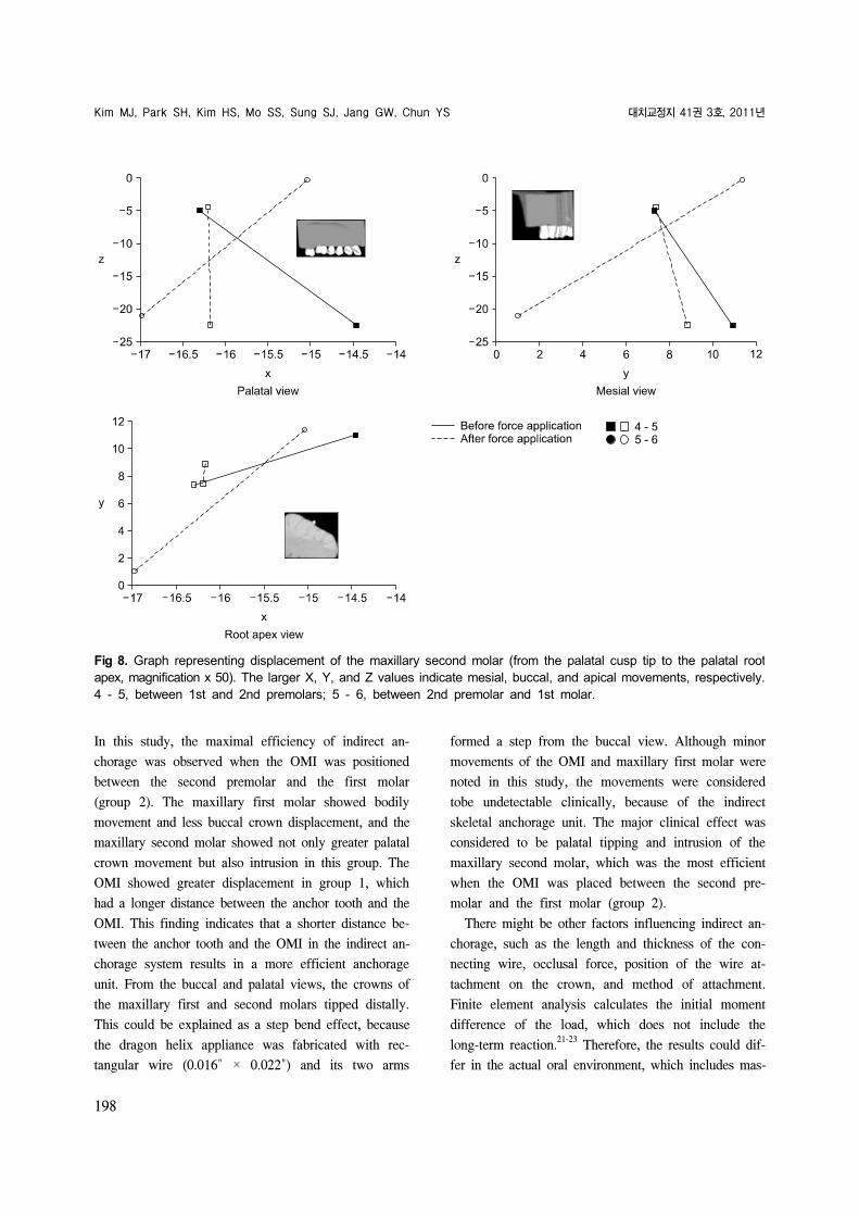
Fig 8. Graph representing displacement of the maxillary second molar (from the palatal cusp tip to the palatal rootapex, magnification x 50). The larger X, Y, and Z values indicate mesial, buccal, and apical movements, respectively.4 - 5, between 1st and 2nd premolars; 5 - 6, between 2nd premolar and 1st molar.
In this study, the maximal efficiency of indirect an-
chorage was observed when the OMI was positioned
between the second premolar and the first molar
(group 2). The maxillary first molar showed bodily
movement and less buccal crown displacement, and the
maxillary second molar showed not only greater palatal
crown movement but also intrusion in this group. The
OMI showed greater displacement in group 1, which
had a longer distance between the anchor tooth and the
OMI. This finding indicates that a shorter distance be-
tween the anchor tooth and the OMI in the indirect an-
chorage system results in a more efficient anchorage
unit. From the buccal and palatal views, the crowns of
the maxillary first and second molars tipped distally.
This could be explained as a step bend effect, because
the dragon helix appliance was fabricated with rec-
tangular wire (0.016" × 0.022") and its two arms
formed a step from the buccal view. Although minor
movements of the OMI and maxillary first molar were
noted in this study, the movements were considered
tobe undetectable clinically, because of the indirect
skeletal anchorage unit. The major clinical effect was
considered to be palatal tipping and intrusion of the
maxillary second molar, which was the most efficient
when the OMI was placed between the second pre-
molar and the first molar (group 2).
There might be other factors influencing indirect an-
chorage, such as the length and thickness of the con-
necting wire, occlusal force, position of the wire at-
tachment on the crown, and method of attachment.
Finite element analysis calculates the initial moment
difference of the load, which does not include the
long-term reaction.21-23
Therefore, the results could dif-
fer in the actual oral environment, which includes mas-
Vol. 41, No. 3, 2011. Korean J Orthod Effects of the position of mini-implant
199
ticatory force, complex anatomical structures, other bi-
ological features, and the combination of these factors.
Further studies should focus on the effects of these
factors on indirect anchorage with this system.
CONCLUSION
Three-dimensional FEA of the dragon helix appli-
ance combined with the OMI-based indirect skeletal
anchorage indicated that placement of the OMI be-
tween the maxillary second premolar and the maxillary
first molar enables more efficient anchorage and great-
er movement for scissors-bite correction than place-
ment of the OMI between the maxillary first and the
maxillary second premolars.
REFERENCES
1. Yun SW, Lim WH, Chong DR, Chun YS. Scissors-bite correc-tion on second molar with a dragon helix appliance. Am J Orthod Dentofacial Orthop 2007;132:842-7.
2. Harper DL. A case report of a Brodie bite. Am J Orthod Dentofacial Orthop 1995;108:201-6.
3. Orton-Gibbs S, Orton S, Orton H. Eruption of third permanent molars after the extraction of second permanent molars. Part 2: Functional occlusion and periodontal status. Am J Orthod Dentofacial Orthop 2001;119:239-44.
4. Ramsay DS, Wallen TR, Bloomquist DS. Case report MM. Surgical-orthodontic correction of bilateral buccal crossbite (Brodie syndrome). Angle Orthod 1990;60:305-11.
5. Kucher G, Weiland FJ. Goal-oriented positioning of upper sec-ond molars using the palatal intrusion technique. Am J Orthod Dentofacial Orthop 1996;110:466-8.
6. Chun YS, Woo YJ, Row J, Jung EJ. Maxillary molar intrusion with the molar intrusion arch. J Clin Orthod 2000;34:90-3.
7. Legan HL. Orthodontic planning and biomechanics for trans-verse distraction osteogenesis. Semin Orthod 2001;7:160-8.
8. Park YC, Lee SY, Kim DH, Jee SH. Intrusion of posterior
teeth using mini-screw implants. Am J Orthod Dentofacial Orthop 2003;123:690-4.
9. Kanomi R. Mini-implant for orthodontic anchorage. J Clin Orthod 1997;31:763-7.
10. Cope JB. Temporary anchorage devices in orthodontics: a paradigm shift. Semin Orthod 2005;11:3-9.
11. Celenza F, Hochman MN. Absolute anchorage in orthodontics: direct and indirect implant-assisted modalities. J Clin Orthod 2000;34:397-402.
12. Kyung SH, Choi HW, Kim KH, Park YC. Bonding ortho-dontic attachments to miniscrew heads. J Clin Orthod 2005; 39:348-53.
13. Kyung SH, Lim JK, Park YC. The use of miniscrew as an an-chorage for the orthodontic tooth movement. Korean J Orthod 2001;31:415-24.
14. Bae SM, Park HS, Kyung HM, Kwon OW, Sung JH. Clinical application of micro-implant anchorage. J Clin Orthod 2002; 36:298-302.
15. Park HS, Kwon OW, Sung JH. Uprighting second molars with micro-implant anchorage. J Clin Orthod 2004;38:100-3.
16. Park HS. Orthodontic treatment using micro-implant. 2nd ed. Seoul: Daehan Narae Publishing Inc., 2006. p. 1-414.
17. Wilmes B, Su YY, Drescher D. Insertion angle impact on pri-mary stability of orthodontic mini-implants. Angle Orthod 2008;78:1065-70.
18. Lee KJ, Joo E, Kim KD, Lee JS, Park YC, Yu HS. Computed tomographic analysis of tooth-bearing alveolar bone for ortho-dontic miniscrew placement. Am J Orthod Dentofacial Orthop 2009;135:486-94.
19. Lim JE, Lim WH, Chun YS. Cortical bone thickness and root proximity at mandibular interradicular sites: implications for orthodontic mini-implant placement. Korean J Orthod 2008;38: 397-406.
20. Park HS. An anatomical study using CT images for the im-plantation of micro-implants. Korean J Orthod 2002;32:435-41.
21. Kim CN, Sung JH, Kyung HM. Three-dimensional finite ele-ment analysis of initial tooth displacement according to force application point during maxillary six anterior teeth retraction using skeletal anchorage. Korean J Orthod 2003;33:339-50.
22. Cheon OJ, Kim TW, Suhr CH. Three-dimentional finite ele-ment analysis of the phenomenon produced during retraction of four maxillary incisors. Korean J Orthod 1995;25:525-41.
23. Yoon HJ, Lim YK, Lee DY, Jo YS. Three-dimensional finite element analysis on the effect of maxillary incisor torque. Korean J Orthod 2005;35:137-47.