Effects of Geogrid Layers on Improving Bearing Capacity of ...
16
Journal of New Approaches in Civil Engineering (ISSN PRINT: 2588-6886 ) - ( ISSN ONLINE: 2588-7122)-Vol.2, No.2, Pages: 11-26. 11 Effects of Geogrid Layers on Improving Bearing Capacity of Vibrating Machines Foundation Amir Hossain Khodayari 1, 2 , Rouzbeh Dabiri 3* 1 M.Sc. of Geotechnical Engineering, Department of Civil Engineering, Tabriz Branch, Islamic Azad University, Tabriz, Iran. 2 M.Sc. of Geotechnical Engineering, Department of Civil Engineering, East Azerbaijan Science and Research Branch, Islamic Azad University, Tabriz, Iran. *3 Assistant Professor, Department of Civil Engineering, Tabriz Branch, Islamic Azad University, Tabriz, Iran. ([email protected]) ABSTRACT The main aim of this study is an investigating the effect of using geogrid layers in the reinforcement of soil under the foundation to estimate the reaction of industrial machines’ foundations under periodic loading based on finite element method using ABAQUS software. Also, the effect of the number of geogrid layers, the effect of depth and width of geogrid, different loading frequencies along with the effect of using geogrid layers on the first to the third modes of frequency values of the soil were evaluated. The results showed that as the number of geogrid layers increases, bearing capacity of foundation rises and the optimum depth of geogrid layers for dynamic mode is equal to 0.6 times the width of the foundation strip. Furthermore, increasing frequency of dynamic load does not lead to a significant change in capacity. Keywords: Vibrating machine foundation, Improving, Geogrid, Periodic loading, Bearing capacity.
Transcript of Effects of Geogrid Layers on Improving Bearing Capacity of ...

Journal of New Approaches in Civil Engineering (ISSN PRINT: 2588-6886 )- ( ISSN ONLINE: 2588-7122)-Vol.2, No.2, Pages: 11-26.
11
Effects of Geogrid Layers on Improving Bearing Capacity of
Vibrating Machines Foundation
Amir Hossain Khodayari1, 2, Rouzbeh Dabiri3*
1M.Sc. of Geotechnical Engineering, Department of Civil Engineering, Tabriz Branch, Islamic Azad University,
Tabriz, Iran.
2 M.Sc. of Geotechnical Engineering, Department of Civil Engineering, East Azerbaijan Science and Research
Branch, Islamic Azad University, Tabriz, Iran.
*3 Assistant Professor, Department of Civil Engineering, Tabriz Branch, Islamic Azad University, Tabriz, Iran.
ABSTRACT
The main aim of this study is an investigating the effect of using geogrid layers in the
reinforcement of soil under the foundation to estimate the reaction of industrial machines’
foundations under periodic loading based on finite element method using ABAQUS software. Also,
the effect of the number of geogrid layers, the effect of depth and width of geogrid, different loading
frequencies along with the effect of using geogrid layers on the first to the third modes of frequency
values of the soil were evaluated. The results showed that as the number of geogrid layers increases,
bearing capacity of foundation rises and the optimum depth of geogrid layers for dynamic mode is
equal to 0.6 times the width of the foundation strip. Furthermore, increasing frequency of dynamic
load does not lead to a significant change in capacity.
Keywords: Vibrating machine foundation, Improving, Geogrid, Periodic loading, Bearing capacity.

Journal of New Approaches in Civil Engineering (ISSN PRINT: 2588-6886 )- ( ISSN ONLINE: 2588-7122)-Vol.2, No.2, Pages: 11-26.
12
1. Introduction
Soil, as the most important building material and the main support structure, is of interest to
engineers. However, due to the discontinuous structure and lack of shear strength along with lack
of resistance to tensile forces, the researchers have constantly been looking for the ways to increase
bearing capacity, resistance, and improvement of soil properties through various methods
including mechanical corrections such as density, chemical modification such as stabilization with
lime, and the use of reinforcements such as variety of geosynthetics. Soil reinforcement is known
as an effective and reliable method to reform the soil due to its resistance to environmental
conditions, ease of implementation, cost-effectiveness, and high impact in improving soil
properties. Geosynthetics are actually artificial products made of polymeric compounds and are
used in constructional activities. One important use of geosynthetics in construction projects is
their use as reinforcement in the manufacture of industrial machines’ foundations. Geosynthetics,
according to the type of ingredients and manufacturing methods, have various applications in the
construction processes such as materials separation from each other, reinforcement and
strengthening of soil, water filtration in marine structures, drainage, and sealing. According to the
types of mentioned applications and projects conditions, many researchers have worked on this
subject. Raymound and Comos [1] investigated the behavior of the surface strip foundations under
vertical cyclic loadings and reported that the permanent settlement rises with an increase in the
number of cycles and its time. Poulos [2] investigated foundation types on sandy soils and
conducted some experiments on foundation models on sand with various relative densities of
vertical cyclic loadings. Yeo et al. [3] investigated ultimate bearing capacity and settlement of
rectangular and strip foundations on the network of reinforced sand exposed to synchronized static
and cyclic vertical loads with varying degrees of intensity. Arayee [4] focused on experimental
and numerical studies of sandy trenches reinforced with geosynthetic under a loading foundation.
Sarand et al. [5] conducted a research about the behavior of reinforced and non-reinforced sandy
soils under the strip foundation. This study investigated the failure mechanism of sandy soil
deformation, and reinforcement effect on the process under a strip foundation. Zamani et al. [6]
examined bearing capacity of surface foundation based on sand reinforced with chip worn tires

Journal of New Approaches in Civil Engineering (ISSN PRINT: 2588-6886 )- ( ISSN ONLINE: 2588-7122)-Vol.2, No.2, Pages: 11-26.
13
using static analysis. The results indicated that the usage leads to an increase in bearing capacity
to a large extent and significantly amortizes earthquake vibrations. Gholamhoseinpour and Soltani
[7] conducted a research on bearing capacity of foundations to compare different methods for
determining the bearing capacity. Besides, the effect of parameters such as joint inclination angle
along with cohesion parameters of the rock mass and fractures were examined on the bearing
capacity strip foundation. Nazari and Dabiri [8] studied to explore the effect of geotextile layers
place in various depths of the body of pavement layers located on soft soil. Results showed that in
static loading, the maximum safety factor of stability is that of layers in which the geotextile exists
in the partition between subgrade and embankment layers. Also, between dynamic loading and
increasing number of geotextile layers favorable result is not achieved. Although more studies
need to be carried out in this area.
2. Foundation design and soil reinforced
Based on the literature review and previous work and the results of conducted laboratory
studies, four modes of failure for foundations located on reinforced soil was proposed as presented
in Figure 1. A) Failure above the top layer of reinforcements (Binquet and Lee, [9]) B) Failure
between the two reinforce layers (Wayne et al., [10]) C) Failure similar to foundation failure on
two layers of soil (strong soil layer on the weak soil layer) (Wayne et al., [10]) D) General failure
among the reinforce layers [11]. To avoid the first two types of failures, it suffices to make the top
layer depth (u), and the vertical distance between the layers of reinforcement (h) as small as
possible. Laboratory experiments by Chen [12] and Abu-Farsakh et al. [13] revealed that the top
layer depth (u), and the vertical distance between the layers of reinforcement (h) must be smaller
than 0.5B so that this type of error does not occur (B is foundation width). Compliance with these
considerations is not difficult for engineers, so it is better to examine two other types of failure
modes. Based on the results of experimental studies, geogrids directions in clay or sandy reinforced
soil under ultimate loading would be almost horizontal. Due to its porous and geometric structure,
the soil penetration from one side of geogrid is allowed to the other side. As a result, punching

Journal of New Approaches in Civil Engineering (ISSN PRINT: 2588-6886 )- ( ISSN ONLINE: 2588-7122)-Vol.2, No.2, Pages: 11-26.
14
effect of the reinforcement mechanism powering over clay or sandy soils is reinforced with
geogrid. As mentioned earlier, punching effect could resist the possible lateral deformation or
tensile strain in the soil. This results in an increase in the bearing capacity of the soil under the
foundation and is the prerequisite for their use.
Fig 1. Failure modes of reinforced soil foundation, (a) Failure above top layer reinforcement [9], (b) Failure between
reinforcement layers [10], (c) Failure similar to footings on a two-layer soil system [10], (d) Failure within
reinforced zone.
3. Numerical modelling
In the present investigation, the created area had a width and height of 10×10 m, respectively.
This is suitable for foundation strip with a width of 2=B m. However, for accuracy in modeling,
we used unlimited elements for modeling boundary conditions. Besides, foundation behavior is
assumed to be rigid and its rigidity effect is only considered in modeling using boundary
conditions. Generally, small meshing is used in the whole model and based on the model analysis
done to test sensitivity of the results to the size of mesh. Size of the elements was considered to be
0.5 meter. Sharma [11] proposed the dimensions of the area of foundation failure spread with a

Journal of New Approaches in Civil Engineering (ISSN PRINT: 2588-6886 )- ( ISSN ONLINE: 2588-7122)-Vol.2, No.2, Pages: 11-26.
15
width of B5 and depth of B3 for the central foundations points for foundation-based granular
soils. In the current research, the width and depth of the critical section was considered 3B with
respect to foundation central point. In the critical area, smaller mesh was used compared to the
general state due to the importance of the deformation and stress concentration. Geometrically, the
distance of the first geogrid layer under the foundation (u) is assumed as the distance between
geogrid layers towards each other (h). The Width of the geogrid layers (b) varied and its optimum
amount is calculated using numerical analysis during the following stages of the research. In
addition, in the expression of boundary conditions, assuming placement of model bottom on the
rigid bed, all degrees of freedom of the bottom edge were bound. Regarding the outer side of the
edges, unlimited elements were used and in the symmetry border, the degrees of freedom were
bound perpendicular to the border.
Fig 2. Numerical model made based on Abaqus software.
The behavior of the soil materials under the foundation is assumed as elastic and in isotropic
stress conditions and its plastic behavior is simulated using Mohr-coulomb model. In the
conducted model, three types of sand soil were used including loose, medium-density, and high-
density. For the geogrid modeling, elastic model was used. Geogrid and soil layers materials’
features are presented in Tables (1) and (2), respectively.

Journal of New Approaches in Civil Engineering (ISSN PRINT: 2588-6886 )- ( ISSN ONLINE: 2588-7122)-Vol.2, No.2, Pages: 11-26.
16
Table 1: Properties of geogrid [11].
Geogrid Unit Parameter
1000 3Kg/m Density
472 MPa Young Modulus (E)
0.3 - Poison ratio
Table 2: Soil layers properties below vibrating machine foundation.
Dense Medium Loose Unit Parameters
1900 1700 1500 3Kg/m Density
300 200 100 mPa Young modulus
0.3 0.3 0.3 - Poison ratio
30 25 20 - Internal friction (φº)
1 1 1 kPa Cohesion
4. Dynamic loading
Loading of foundation strip in this model consists of two stages. In the first stage, the ultimate
bearing capacity of soil (qult) is extracted from the software output. Then, the maximum amount
of bearing capacity of foundation strip, emanating from equation 1, is entered to the foundation as
a linear load to create permanent static settlements in the foundation.
𝑞𝑎𝑙𝑙 =𝑞𝑢𝑙𝑡
𝐹.𝑆 (1)
In the above equation, F.S is the reliability that is usually considered between 3 and 4 which
was chosen to be 3 in the present study. In the second stage of the loading, a percentage of the
ultimate static load (qult) is added to the foundation as a dynamic load in a linear fashion. In this
kind of modeling, dynamic load values for different analyses is assumed as a quarter-final static
load (0.25qult). The load caused by vibration machines entered on the foundation is usually similar
to periodic cycle load presented in Figure 3. In the present study, applied frequency alternating
load was 1, 3, and 6 Hertz (Hz).
Journal of New Approaches in Civil Engineering (ISSN PRINT: 2588-6886 )- ( ISSN ONLINE: 2588-7122)-Vol.2, No.2, Pages: 11-26.
17
Fig 3. Properties of dynamic loading due to vibrating machine.
Finally, to calculate the ultimate bearing capacity of foundation, the loading was modeled as a
displacement control and the one-meter modeled section of the foundation was uniformly
displaced in the vertical direction to enter nonlinear area and reach failure at the end.
5. Results
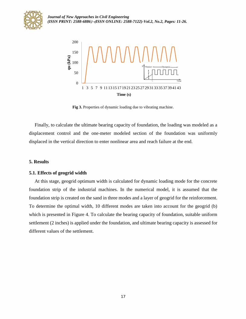
5.1. Effects of geogrid width
At this stage, geogrid optimum width is calculated for dynamic loading mode for the concrete
foundation strip of the industrial machines. In the numerical model, it is assumed that the
foundation strip is created on the sand in three modes and a layer of geogrid for the reinforcement.
To determine the optimal width, 10 different modes are taken into account for the geogrid (b)
which is presented in Figure 4. To calculate the bearing capacity of foundation, suitable uniform
settlement (2 inches) is applied under the foundation, and ultimate bearing capacity is assessed for
different values of the settlement.
0
50
100
150
200
1 3 5 7 9 11 13 15 17 19 21 23 25 27 29 31 33 35 37 39 41 43
qu
(k
Pa
)
Time (s)
Journal of New Approaches in Civil Engineering (ISSN PRINT: 2588-6886 )- ( ISSN ONLINE: 2588-7122)-Vol.2, No.2, Pages: 11-26.
18
Fig 4. Changes of ultimate bearing capacity of foundation versus vertical displacement for values of geogrid layers
width in dense sand.
According to Figure 4, it could be concluded that assuming the width of the geogrid as 2.5 of
foundation strip width, changes in vertical settlement and ultimate bearing capacity in a dynamic
loading conditions reach to an equal amount. As evident in Figure 5, the optimum width for the
geogrid layers changes based on soil density. The optimum width for geogrid increases in line with
the degree of looseness in sandy oil structures. In high-density sandy soil, optimum geogrid width
was b=2.5B, while this was b=3B and b=4B for medium-density and loose soil, respectively.
0
100
200
300
400
500
600
0 1 2 3 4 5 6
qu
(K
Pa
)
Vertical dispalcement(cm)
Without
0.5B
0.75B
0.1.0B
1.25B
1.5B
1.75B
2.0B
2.5B
3.0B
4.0B

Journal of New Approaches in Civil Engineering (ISSN PRINT: 2588-6886 )- ( ISSN ONLINE: 2588-7122)-Vol.2, No.2, Pages: 11-26.
19
Fig 5. Effects of geogrid layers width on bearing capacity of in sandy soil in several density.
5.2. Determining optimum depth of geogrid
The optimum depth placement of geogrid layer was done for dynamic loading of concrete
foundation strip. For modeling, it was assumed that foundation strip is assessed for three different
modes of sand depending on their density. One layer of geogrid was used for the reinforcement.
To determine the optimum amount, five different values are taken into account for the depth of
geogrid (u). These values are presented in Figure 6, and suitable uniform settlement (2 inches) is
applied under the foundation. Ultimate bearing capacity is assessed in high-density soil for
different values of the settlement. As indicated in Figure 7, increasing the depth of reinforcement
elements (u) of 0.2 equal to the width of foundation up 0.6 of foundation of the width leads to a
vertical settlement decline under the foundation affected by the dynamic load.
300
350
400
450
500
550
0 1 2 3 4 5
qu
(k
Pa
)
b/B
dense sand
medium dense sand
loose sand

Journal of New Approaches in Civil Engineering (ISSN PRINT: 2588-6886 )- ( ISSN ONLINE: 2588-7122)-Vol.2, No.2, Pages: 11-26.
20
Fig 6. Effects of geogrid layer locating depth on bearing capacity and vertical displacement.
Fig 7. Effects of geogrid layer locating depth on vertical displacement under dynamic loading.
0
50
100
150
200
250
300
350
400
450
500
0 2 4 6
qu
(K
Pa
)
Vertical displacement (cm)
Without
0.2B
0.4B
0.6B
0.8B
1.0B
0
1
2
3
4
5
6
0 5 10 15
Ver
tica
l d
isp
lace
men
t (c
m)
Time (s)
Without
0.2B
0.4B
0.6B
0.8B
1.0B

Journal of New Approaches in Civil Engineering (ISSN PRINT: 2588-6886 )- ( ISSN ONLINE: 2588-7122)-Vol.2, No.2, Pages: 11-26.
21
As it can be observed in Figure 8, in all types of sand soil with differing density levels, with an
increase of 0.2 in reinforcement element depth (u) equal to the width of foundation up 0.6, the
bearing capacity of the foundation rises. However, increasing b=0.6B up to b-1B results in a
bearing capacity reduction. That is why the optimal geogrid width is considered b=0.6B for the
dynamic mode.
Fig 8. Effects of geogrid layers locating depth on bearing capacity of in sandy soil at several density.
5.3. Number of geogrid layer
To investigate the effect of the deformations of geogrid layers, the created model consisted of
one to five geogrid layers with a vertical distance of 0.6B. A sample of the research on sandy soil
with high density is presented in Figure 9. As it is indicated in Figures 9 and 10, increasing the
geogrid layers leads to a rise in foundation bearing capacity, and under foundation deformations
continue to a deeper level. This mechanism results in more of the nearby soil to be engaged in the
applied loading and accordingly, the soil could bear more loading.
300
350
400
450
500
550
0 0.2 0.4 0.6 0.8 1 1.2
qu
(k
Pa
)
u/B
dense sand
medium dense sand
loose sand

Journal of New Approaches in Civil Engineering (ISSN PRINT: 2588-6886 )- ( ISSN ONLINE: 2588-7122)-Vol.2, No.2, Pages: 11-26.
22
Fig 9. Effects of number of geogrid layers on bearing capacity of in dense sand.
Fig 10. Effects of number of geogrid layers on bearing capacity in sandy soil at several density.
0
100
200
300
400
500
600
700
0 1 2 3 4 5 6
qu
(K
Pa
)
Vertical displacement (cm)
I layer
II layer
III layer
IV layer
V layer
400
450
500
550
600
650
0 1 2 3 4 5 6
qu
(k
Pa
)
Number of Layer
dense sand
medium dense sand
loose sand

Journal of New Approaches in Civil Engineering (ISSN PRINT: 2588-6886 )- ( ISSN ONLINE: 2588-7122)-Vol.2, No.2, Pages: 11-26.
23
5.4. Effects of loading frequency
To study the effect of dynamic load frequency on foundation settlements, a dynamic load
equivalent to 25% of the ultimate static load with frequencies of 1Hz, 3Hz, and 6Hz were applied
to the foundation. Geogrid used in this analysis was modeled with an optimal length of 2.5 times
the width of foundation and optimal depth of 0.6 of foundation width. Figure 11 presents the
frequency of the possible loading against settlement percentage. As it is illustrated, increasing the
loading frequency from 1Hz to 6Hz, no significant change occurs in the level of vertical settlement
in all different densities of sandy soil.
Fig 11. Effects of dynamic frequency loading on vertical displacement in sandy soil at several density.
6. Conclusion
Due to periodic type of loading in industrial machines and also given the high sensitivity of the
foundations of these machines to displacement and deformation (settlement) of the soil under
foundation, it seems vital to use improved foundations by reinforcements. Thus, it is essential to
3.8
3.85
3.9
3.95
4
4.05
4.1
4.15
4.2
4.25
0 1 2 3 4 5 6 7
Ver
tica
l d
isp
lace
men
t (c
m)
Frequency (Hz)
dense sand
medium dense sand
loose sand

Journal of New Approaches in Civil Engineering (ISSN PRINT: 2588-6886 )- ( ISSN ONLINE: 2588-7122)-Vol.2, No.2, Pages: 11-26.
24
study the usage of reinforcements in increasing the bearing capacity of the foundations and
lowering the amount of possible settlements. As it was mentioned, the objective of the present
article was to investigate the usage possibility of geogrid layers in soil reinforcement under
foundation to fathom the behavior of the periodic loading foundation caused by vibrating
machinery. The results could be summarized as follows:
1. Ultimate bearing capacity of the foundation for different values of the geogrid is an optimal
value and does not change significantly after increasing geogrid width of the bearing capacity. In
this study, the optimum width of the geogrid in the dynamic mode was determined in three
different densities for the foundation strip based on the sand. The results showed that bearing
capacity in the dynamic mode rises by increasing the width of the geogrid. Thus, geogrid optimum
width for dynamic load was evaluated to be b=2.5B, b=3B and b=4B for high-, medium-density,
and loose soil, respectively.
2. The results of the study also revealed that with an increase of 0.2 in reinforcement element
width (u) equal to the width of foundation up 0.6, the bearing capacity of the foundation rises.
However, increasing b=0.6B up to b-1B results in bearing capacity reduction. That is why the
optimal geogrid width is considered b=0.6B for the dynamic mode. This condition holds true for
all sand soil density modes.
3. The findings, in addition, proved that increasing the geogrid layers leads to foundation
bearing capacity growth, and under foundation deformations continues to a deeper level. This
mechanism results in more of the nearby soil to be engaged in the applied loading, and
consequently, the soil could bear more loading. The more the layers get, the more the gradient of
the changes declines.
4. Then, dynamic load equivalent to 25% of the ultimate static load with frequencies of 1Hz,
3Hz, and 6Hz were applied to the foundation. Geogrid used in this analysis was modeled with an
optimal length of 2.5 times the width of foundation and optimal depth of 0.6 of foundation width.
It could be deduced that reinforcements affect resistance more than frequency.
Based on the results of the present study, it could be stated that the use of geosynthetic materials
is very effective in soil improvement under foundations in vibrating machines. However, it is also

Journal of New Approaches in Civil Engineering (ISSN PRINT: 2588-6886 )- ( ISSN ONLINE: 2588-7122)-Vol.2, No.2, Pages: 11-26.
25
suggested that further research need to be conducted on the use of other geosynthetic materials
in soil improvement under the foundations of industrial machines. Furthermore, seismic behavior
of the soil and dynamic responses of the foundation in these machines are important and warrant
further investigation.
References
[1]- Raymound, G. P. and Comos, F. E. (1978). Repeat load testing of a model plane strain footing,
Canadian Geotechnical Journal, 15, 90-101.
[2]- Poulos, H., Aust, F. and Chua, E. (1986). Bearing capacity on calcareous sand, Research
report, University of Sydney.
[3]- Yeo, S. C. Yen, Puri, V. K., Das, B. M. and Wright M. A. (1993). A laboratory investigation
into the settlement of a foundation on geogrid-reinforced sand due to cyclic load, Geotechnical
and Geological Engineering, 11,1-14.
[4]- Arayee, A. A. (2001). Laboratory and numerical study of sandy cut reinforced by geosynthetic
under foundation loading, 1st Conference of Soil Improvement, Tehran, Iran (In Persian)
[5]- Sarand B.,F., Hajialilue, M. and Katebi, H. (2010). Study of reinforced and unreinforced sandy
soil under strip foundation with using P.I.V. method, 4th Conference of Geotechnique and Soil
Mechanic, Tehran, Iran. (In Persian).
[6]- Zamani, M., Amelsakhi, M. and Hjiyan Nia, A. (2012). Study of bearing capacity of shallow
foundation locating on reinforced sandy soil with tyre chips under quasi static loading, 9th
International Conference of Civil Engineering, Tehran, Iran. (In Persian)
[7]- Gholamhoseinpour, A. and Soltani, F. (2011). Comparison of methods of determining bearing
capacity of foundation under rock, 1st International Conference and 3rd National Conference of
Dam and planets, Tehran, Iran. (In Persian).
[8]- Nazari, R. and Dabiri, R. (2016). Comparison of geotextile layers effects on static and dynamic
behavior of pavement, Journal of Structural Engineering and Geotechnique, 6(1), 15-22.
[9]- Binquet, J., Lee, K. L. (1975). Bearing capacity of analysis on reinforced earth slabs, Journal
of Geotechnical Division, ASCE, 101, 1257-1276.
[10]- Wayne, M. H., Han, J. and Akins, K. (1998). The design of geosynthetic reinforced
foundation”, In: Proceedings of ASCE’s 1998 Annual Convention & Exposition, ASCE
Geotechnical Special Publication, 76, 1-18.
[11]- Sharma, R., Chen, Q., Abu-Farsakh, M. and Yoon, S. (2009). Analytical modelling of
geogrid reinforced soil foundation, Geotextile and Geomembranes, 27, 63-72.

Journal of New Approaches in Civil Engineering (ISSN PRINT: 2588-6886 )- ( ISSN ONLINE: 2588-7122)-Vol.2, No.2, Pages: 11-26.
26
[12]- Chen, Q., Abu-Farsakh, M., Sharma, R. and Zhang, X. (2007). Laboratory investigation of
behavior of foundation on geosynthetic-reinforced clayey soil, Transportation Research Record:
Journal of the Transportation Board 2004, 28-38.
[13]- Abu-Farsakh, M., Chen, Q., Yoon, S. (2008), Use of Reinforced Soil Foundation (RSF) to
Support Shallow Foundation, Final Report. Louisiana Transportation Research, Center (LTRC),
Louisiana Department of Transportation and Development, (LADOTD), Baton Rouge, LA, Report
No. FHWA/LA.07/424, 195.