
Effects of Electromagnetic Field Intensity on Gas Metal ... · Effects of Electromagnetic Field...
4
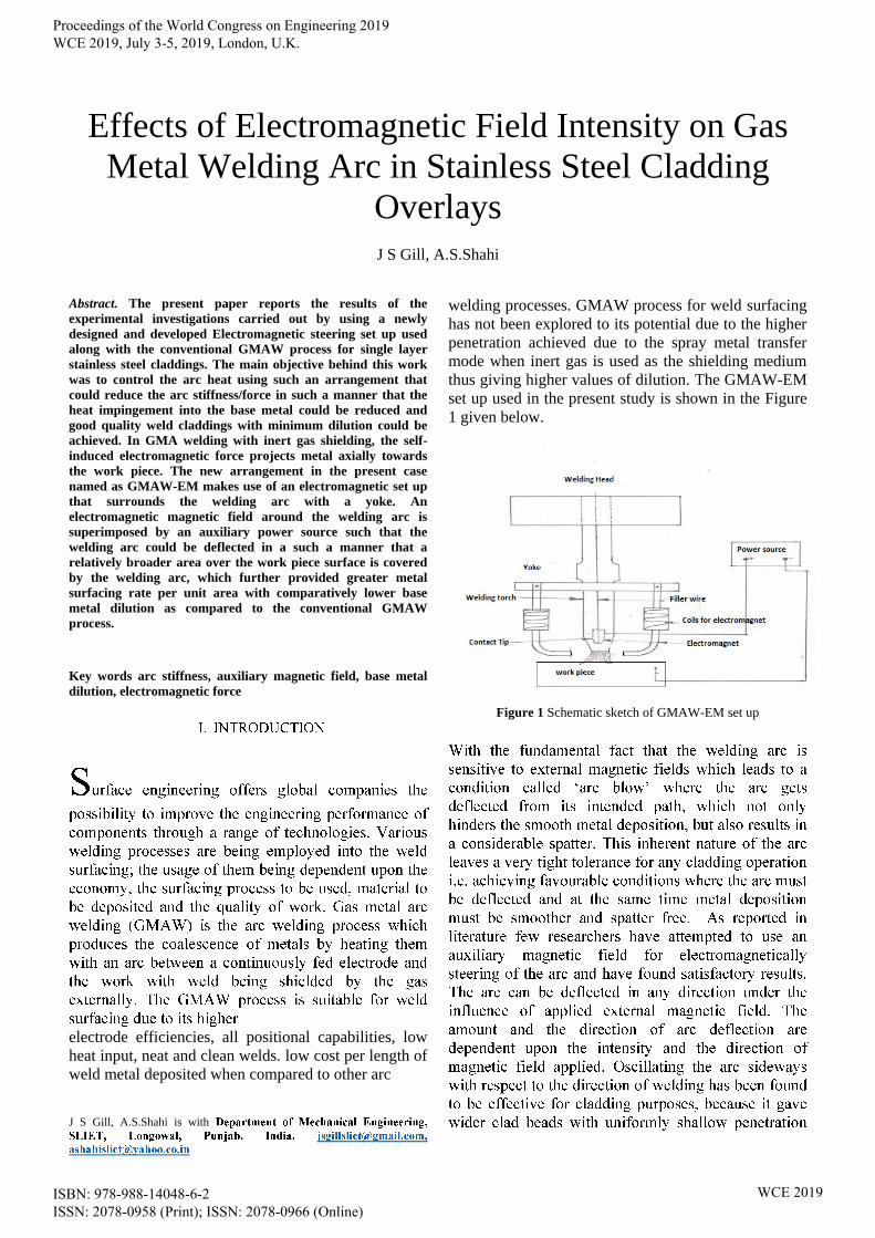
Effects of Electromagnetic Field Intensity on Gas Metal Welding Arc in Stainless Steel Cladding Overlays J S Gill, A.S.Shahi Abstract. The present paper reports the results of the experimental investigations carried out by using a newly designed and developed Electromagnetic steering set up used along with the conventional GMAW process for single layer stainless steel claddings. The main objective behind this work was to control the arc heat using such an arrangement that could reduce the arc stiffness/force in such a manner that the heat impingement into the base metal could be reduced and good quality weld claddings with minimum dilution could be achieved. In GMA welding with inert gas shielding, the self- induced electromagnetic force projects metal axially towards the work piece. The new arrangement in the present case named as GMAW-EM makes use of an electromagnetic set up that surrounds the welding arc with a yoke. An electromagnetic magnetic field around the welding arc is superimposed by an auxiliary power source such that the welding arc could be deflected in a such a manner that a relatively broader area over the work piece surface is covered by the welding arc, which further provided greater metal surfacing rate per unit area with comparatively lower base metal dilution as compared to the conventional GMAW process. Key words arc stiffness, auxiliary magnetic field, base metal dilution, electromagnetic force electrode efficiencies, all positional capabilities, low heat input, neat and clean welds. low cost per length of weld metal deposited when compared to other arc J S Gill, A.S.Shahi is with welding processes. GMAW process for weld surfacing has not been explored to its potential due to the higher penetration achieved due to the spray metal transfer mode when inert gas is used as the shielding medium thus giving higher values of dilution. The GMAW-EM set up used in the present study is shown in the Figure 1 given below. Figure 1 Schematic sketch of GMAW-EM set up Proceedings of the World Congress on Engineering 2019 WCE 2019, July 3-5, 2019, London, U.K. ISBN: 978-988-14048-6-2 ISSN: 2078-0958 (Print); ISSN: 2078-0966 (Online) WCE 2019
Transcript of Effects of Electromagnetic Field Intensity on Gas Metal ... · Effects of Electromagnetic Field...
Effects of Electromagnetic Field Intensity on Gas
Metal Welding Arc in Stainless Steel Cladding
Overlays
J S Gill, A.S.Shahi
Abstract. The present paper reports the results of the
experimental investigations carried out by using a newly
designed and developed Electromagnetic steering set up used
along with the conventional GMAW process for single layer
stainless steel claddings. The main objective behind this work
was to control the arc heat using such an arrangement that
could reduce the arc stiffness/force in such a manner that the
heat impingement into the base metal could be reduced and
good quality weld claddings with minimum dilution could be
achieved. In GMA welding with inert gas shielding, the self-
induced electromagnetic force projects metal axially towards
the work piece. The new arrangement in the present case
named as GMAW-EM makes use of an electromagnetic set up
that surrounds the welding arc with a yoke. An
electromagnetic magnetic field around the welding arc is
superimposed by an auxiliary power source such that the
welding arc could be deflected in a such a manner that a
relatively broader area over the work piece surface is covered
by the welding arc, which further provided greater metal
surfacing rate per unit area with comparatively lower base
metal dilution as compared to the conventional GMAW
process.
Key words arc stiffness, auxiliary magnetic field, base metal
dilution, electromagnetic force
electrode efficiencies, all positional capabilities, low
heat input, neat and clean welds. low cost per length of
weld metal deposited when compared to other arc
J S Gill, A.S.Shahi is with
welding processes. GMAW process for weld surfacing
has not been explored to its potential due to the higher
penetration achieved due to the spray metal transfer
mode when inert gas is used as the shielding medium
thus giving higher values of dilution. The GMAW-EM
set up used in the present study is shown in the Figure
1 given below.
Figure 1 Schematic sketch of GMAW-EM set up
Proceedings of the World Congress on Engineering 2019 WCE 2019, July 3-5, 2019, London, U.K.
ISBN: 978-988-14048-6-2 ISSN: 2078-0958 (Print); ISSN: 2078-0966 (Online)
WCE 2019

Feasibility studies through screening experiments
were carried out by using the Electromagnetic steering
set up used with the conventional GMAW process for
single layer ‘Bead on plate experimentation of
stainless steel claddings. The main motive behind this
work was to control the arc heat by deflecting the arc
so as to reduce the arc stiffness/force such that good
quality and consistent weld claddings with minimum
dilution could be achieved. The outcome of these
preliminary investigations was found to be
encouraging in terms of achieving higher productivity
of the conventional GMAW process when EM set up
as shown in Figure 1 was used for the same set of
input welding conditions.
The experimental details and the findings obtained are
briefly summarized as below: -
Wire feed rate = 5 m/min, Arc voltage = 24.8 V,
Welding speed = 22 cm/min, Nozzle-to-plate distance
= 15 mm, Electrode to work angle = 90º, Gas flow rate
(Industrially pure argon) = 18L/min, Welding
position= Flat, Level of automation = Fully automatic,
Auxiliary magnetic field intensity used at the axis of
the arc = 150 Gauss (corresponding to a voltage of
16V supplied to the electromagnet using DC power
source), Base material and thickness used = Low
carbon structural steel AISI 1020 thickness =,12 mm,
Filler wire used = Austenitic stainless steel solid wire
(E309L of 1.2 mm diameter)
For revealing the weld profiles, the specimens were cut
from the centre of the plates (since equilibrium
conditions are achieved here) and prepared using
standard metallographic procedures of grinding,
polishing, lapping and etching. The weld bead
comparison is shown in Figure 2 given below of (1)
GMAW-EM and (2) conventional GMAW techniques.
Figure 2 Bead on plate comparisons between (1) GMAW-EM
and (2) conventional GMAW processes
As seen from Figure 2 (1and 2), distinct differences
were observed i.e. GMAW-EM bead has more width
and reinforcement with significantly low penetration,
and consequently negligible dilution (although for
ensuring bond integrity with the base metal there has
to be a minimum dilution of around 5 %)
Table 2: Bead geometry comparisons (GMAW v/s GMAW-
EM)
Bead geometry
parameters
Weld bead -1
(GMAW-EM)
Weld bead- 2
(GMAW)
Bead width (mm) 13.70 8.80
Bead height (mm) 5.82 4.60
Penetration depth
(mm)
Negligible 2.00
Further these welding conditions were used to
fabricate the clad overlays with SS filler wires E316L
for clad overlays and E309L for buttering layers.
Figure 3 shows the fabricated clad overlay by GMAW-
EM setup
Figure 3 Multi-layer and multi-pass clad overlays
The metallographic examination and corrosion rate
was examined from the samples cut from these
specimens, the results of which are discussed ahead.
III. RESULTS AND DISCUSSION
The welding arc responded instantly to the
externally applied magnetic field. The arc deflected at
right angle to the axis of the weld bead when the
electromagnetic field was applied in the longitudinal
direction. A subsequent increase in the width of the
weld bead about 33 % increase as compared to
conventional GMAW process was obtained under
these conditions.
Besides this, since the volume of the metal melted
remains the same for each parametric combination
(which is decided by the wire feed rate) decrease in
weld penetration results in increased reinforcement of
the weld bead. These are the conditions which are
most favourable for any cladding operation i.e. less
penetration depth and consequently low dilution,
accompanied by wide and peaked weld beads.
1 2
Proceedings of the World Congress on Engineering 2019 WCE 2019, July 3-5, 2019, London, U.K.
ISBN: 978-988-14048-6-2 ISSN: 2078-0958 (Print); ISSN: 2078-0966 (Online)
WCE 2019

Since the weld metal ferrite content can influence a
wide range of properties which include corrosion
resistance and resistance to hot cracking or micro
fissuring. Small amount of BCC ferrite commonly
known as delta ferrite, in the austenite which is
predominantly FCC structure is observed in the
austenitic stainless steels. The amount of delta ferrite
present in the claddings was measured across different
locations of the clad to check the tendency of
microfissuring/solidification cracking. Ferrite
measurements were carried out in accordance to the
standard test procedures for steel casting austenitic
alloy, estimating ferrite content (ASTM A800 M-14).
Delta ferrite measurements were found to be lying
within the range of 5.5% to 8% which is assumed to be
beneficial for the austenitic stainless steels to resist the
tendency of hot cracking.
To study the microstructure of the specimens of a
suitable size 25 25 square mm were fabricated using
a wire cut EDM machine with a thickness of 4 mm
from the weld pads or fully cladded plates as shown in
Figure 4. Standard polishing methods were adopted for
general microstructure observations as per ASTM E
407-07 (ASTM, 2007). The specimens were polished
on a twin disc polishing machine with emery papers of
grit size starting from 60, 100, 200, 400, 600, 800,
1000, 1200 and 1400 followed by velvet cloth
polishing with diamond paste. Figure 5 shows a
comparative look of the microstructures obtained of
clad overlays by conventional GMAW process and by
using GMAW-EM set up.
The boiling nitric acid or Huey’s test was used for
testing the susceptibility of stainless steel cladding
towards inter-granular corrosion attack and to calculate
the corrosion rate in terms of material loss per unit
time, which was conducted as per ASTM A-262-
Practice-C. The entire lateral surfaces of the prepared
test specimens were finely grounded and polished to
facilitate better surface exposure to the corrosive test
solution. A 65 % by weight nitric acid solution was
prepared by adding distilled water to concentrated
nitric acid (HNO3) of reagent grade with specific
gravity 1.42 at the rate of 108 ml of distilled water per
litre of concentrated nitric acid. The specimens were
polished with 120 grit abrasive paper and weighed
initially. The specimens were placed in a glass cradle
and kept inside the round bottom boiling flask fitted
with condenser to dissipate the heat developed during
boiling of the acid. The corrosion rate was calculated
by the following formula recommended for stainless
steels according to ASTM A262 G1:
Corrosion rate (mm/month) =
Where, ‘t’ is the time of exposure in hours, ‘A’ is the
total surface area in cm2; ‘W’ is the weight loss in
grams and ‘d’ is the density, where for chromium–
nickel–molybdenum stainless steels it is taken as 8
g/cm3. Average corrosion rate was found to be 0.062
inch per month and 0.047 inch per month for the
specimens by GMAW and GMAW-EM techniques
which show a significant improvement in the corrosion
rate by the specimens fabricated by GMAW-EM
process.
Figure 5 (A) Photomicrograph showing the ferrite morphology in
stainless steel weld metal with conventional GMAW process
Figure 5 (B) Photomicrograph showing more distinct ferrite
morphology in stainless steel weld metal in austenitic matrix of
stainless steel weld metal produced with GMAW-EM set up
Proceedings of the World Congress on Engineering 2019 WCE 2019, July 3-5, 2019, London, U.K.
ISBN: 978-988-14048-6-2 ISSN: 2078-0958 (Print); ISSN: 2078-0966 (Online)
WCE 2019
IV. CONCLUSIONS
The following conclusions can be drawn from the
study:
1. The arc of the GMAW process could be
controlled by controlling the direction and
magnetic field intensity for controlling dilution
to a minimum value for stainless steel
claddings.
2. The GMAW-EM process resulted in weld
beads with significantly higher width, larger
reinforcement and low depth of penetrations
compared to the conventional GMAW weld
beads.
3. EM-GMAW weld beads had narrower HAZ
besides weld metal grains possessing planar
growth.
4. The EM-GMAW process showed the
capability of enhancing the productivity of the
conventional GMA process for stainless steel
cladding, both in terms of economy as well as
quality as resulted from the corrosion rate
measurements.
REFERENCES
[1] Modeling of the Effects of Welding Conditions on Dilution of
Stainless Steel Claddings Produced by Gas Metal Arc Welding
Procedures, by A S Shahi and Sunil Pandey. Journal of material
process technology 196(2008), 339-344.
[2] Magnetic Steering of Arc and Bead Characteristics in Submerged Arc
Strip Cladding, by Mallya U D and Sriniwas H, Welding Journal 72
(11) pp 517s-522s, 1993.
[3] Effect of Magnetic Steering of the Arc on Clad Quality in Submerged
Arc Strip Cladding, by Mallya U D and Sriniwas H, Welding Journal
72 (11) pp 289s-293s, 1993.
[4] A Study on the Modeling of Magnetic Arc Deflection and Dynamic
Analysis of Arc Sensor by YH Kang and S J NA, pp 8s-13s AWS
Welding Research Supplement January 2002.
[5] A. Chakrabarti, H. Das, S. Das, and T. K. Pal, 2013, Effect of process
parameters on clad quality of duplex stainless steel using GMAW
process. Transactions of Indian Institute of Metals, 66(3): 221–230.
[6] G.H. Aydog˘du, and M.K. Aydinol, ‘Determination of susceptibility
to intergranular corrosion and electrochemical reactivation behaviour
of AISI 316L type stainless steel’, Corrosion Science 48, (2006), p
3565–3583.
[7] Bachelis, I. A., ‘Calculation of deflection of welding arc in a constant
transverse magnetic field’, Welding Production, 10 (7), (1963), p15-
18.
[8] Bonifaz, ‘Finite Element Analysis of Heat Flow in Single-Pass Arc
Welds’, Welding Journal, (2000) p 121s-125s.
[9] C.T. Kwok, S.L. Fong, F.T. Cheng, and H.C. Man, ‘Pitting and
galvanic corrosion behavior of laser-welded stainless steels’, Journal
of Materials Processing Technology 176, (2006), p 168–178.
[10] Carlos Eduardo Iconomos Baixo and Jair Carlos Dutra, ‘Effect of
shielding gas and transfer mode on the application of 625 alloy in
carbon steel’, Welding International (25) (12), (2011), p 903–909.
[11] Chen Guoqing, Fu Xuesong, Wei Yanhui, Li Shan, and Zhou
Wenlong, ‘Microstructure and wear properties of Nickel-based
surfacing deposited by plasma transferred arc welding’, Surface &
Coatings Technology 228, (2013), p S276–S282.
[12] Deacon, R. M., Dupont, J. N., and Marder, A. R., ‘High temperature
corrosion resistance of candidate nickel-based weld overlay alloys in
a low NOx environment’, Material Science and Engineering, AA460-
A461, (2007), p 392–402.
[13] Deminskii, Y. A., and Dyatlov, V. I. Magnetic control during gas
shielded arc welding with a consumable electrode. Automatic
Welding (4) (1963), p 67–68.
Proceedings of the World Congress on Engineering 2019 WCE 2019, July 3-5, 2019, London, U.K.
ISBN: 978-988-14048-6-2 ISSN: 2078-0958 (Print); ISSN: 2078-0966 (Online)
WCE 2019


![Universal intensity statistics in a chaotic …...Electromagnetic (EM) reverberation chambers are com-monly used for electromagnetic compatibility (EMC) tests [1]. Due to mechanical](https://static.fdocuments.us/doc/165x107/5ea0bb77246a9309cc1deed0/universal-intensity-statistics-in-a-chaotic-electromagnetic-em-reverberation.jpg)

