
Effects of Boundary Conditions on Postbuckling Strengths ...Effects of Boundary Conditions on...
13
Open Journal of Composite Materials, 2013, 3, 38-50 http://dx.doi.org/10.4236/ojcm.2013.32006 Published Online April 2013 (http://www.scirp.org/journal/ojcm) Effects of Boundary Conditions on Postbuckling Strengths of Composite Laminate with Various Shaped Cutouts under In-Plane Shear Dinesh Kumar 1 , Shamsher Bahadur Singh 2* 1 Department of Mechanical Engineering, Malaviya National Institute of Technology (MNIT), Jaipur, India; 2 Department of Civil Engineering, Birla Institute of Technology and Science (BITS), Pilani, India. Email: * [email protected] Received January 16 th , 2013; revised February 10 th , 2013; accepted March 10 th , 2013 Copyright © 2013 Dinesh Kumar, Shamsher Bahadur Singh. This is an open access article distributed under the Creative Commons Attribution License, which permits unrestricted use, distribution, and reproduction in any medium, provided the original work is properly cited. ABSTRACT Cutouts are often provided in composite structural components for practical reasons. For instance, aircraft components such as wingspar, fuselage and ribs are provided with cutouts for access, inspection, fuel lines and electric lines or to reduce the overall weight. This paper addresses the effect of boundary condition on buckling and postbuckling re- sponses, failure loads, and failure characteristics of composite laminate with various shaped cutouts (i.e., circular, square, diamond, elliptical-vertical and elliptical-horizontal) and having different lay-ups under in-plane shear (positive and negative) load, using finite-element method. The FEM formulation is based on the first order shear deformation theory in conjunction with geometric nonlinearity using von Karman’s assumptions. The 3-D Tsai-Hill criterion is used to predict the failure of a lamina while the onset of delamination is predicted by the interlaminar failure criterion. It is observed that the effect of boundary condition on buckling, first-ply failure and ultimate failure loads of a quasi-iso- tropic laminate with cutout is more for positive shear load than that for the negative shear load for almost all cutout shapes. It is also noted that under in-plane shear loads postbuckling stiffness of (0/90) 4s laminate with circular cutout is maximum, while it is minimum for (45/−45) 4s laminate with circular cutout, irrespective of boundary conditions. Keywords: Boundary Conditions; Buckling; Postbuckling; Cutouts; Composite Laminate; FEM 1. Introduction Currently, thin composite laminated panels are used in almost all modern advanced engineering applications such as spacecraft, high speed aircrafts, naval vessels and au- tomobiles because of their superior specific properties (i.e., stiffness-to-weight and strength-to-weight ratios) as compared to their metallic counterparts. Further, cutouts are often provided in these panels for practical considera- tions. For instance, cutouts in wing spars and cover pan- els of commercial transport wings and military fighter wings are provided to form ports for mechanical and ele- ctrical systems, damage inspection, fuel lines, and also to reduce the overall weight of the composite structure. The presence of these cutouts forms free edges in the com- posite laminates under various loading and boundary con- ditions, which in turn cause high interlaminar stresses [1] leading to loss of stiffness and premature failure of la- minate owing to delamination. These composite structu- ral laminates with cutouts are required primarily to resist buckling, and they must carry a load well into the post- buckling range to yield weight savings by utilizing its reserve strength beyond buckling. Further, boundary con- ditions affect the buckling and postbuckling behavior of laminated panels under various loading conditions such as in-plane compression, shear, and combined inplane shear and compression [2-6]. In addition, the shear directions also affect the postbuckling behavior of composite plates [7,8]. Thus, it is imperative to have thorough knowledge of buckling, postbuckling, failure characteristics and streng- th of thin composite panels with cutouts under various edge boundary conditions subjected to in-plane shear (po- sitive and negative) loads, for their cost effective and ef- ficient design. A comprehensive review on buckling and postbuck- ling behavior of laminated composite plates with a cutout by Nemeth [9] has shown that only limited works [10-13] * Corresponding author. Copyright © 2013 SciRes. OJCM
Transcript of Effects of Boundary Conditions on Postbuckling Strengths ...Effects of Boundary Conditions on...

Open Journal of Composite Materials, 2013, 3, 38-50 http://dx.doi.org/10.4236/ojcm.2013.32006 Published Online April 2013 (http://www.scirp.org/journal/ojcm)
Effects of Boundary Conditions on Postbuckling Strengths of Composite Laminate with Various Shaped Cutouts under In-Plane Shear
Dinesh Kumar1, Shamsher Bahadur Singh2*
1Department of Mechanical Engineering, Malaviya National Institute of Technology (MNIT), Jaipur, India; 2Department of Civil Engineering, Birla Institute of Technology and Science (BITS), Pilani, India. Email: *[email protected] Received January 16th, 2013; revised February 10th, 2013; accepted March 10th, 2013 Copyright © 2013 Dinesh Kumar, Shamsher Bahadur Singh. This is an open access article distributed under the Creative Commons Attribution License, which permits unrestricted use, distribution, and reproduction in any medium, provided the original work is properly cited.
ABSTRACT
Cutouts are often provided in composite structural components for practical reasons. For instance, aircraft components such as wingspar, fuselage and ribs are provided with cutouts for access, inspection, fuel lines and electric lines or to reduce the overall weight. This paper addresses the effect of boundary condition on buckling and postbuckling re- sponses, failure loads, and failure characteristics of composite laminate with various shaped cutouts (i.e., circular, square, diamond, elliptical-vertical and elliptical-horizontal) and having different lay-ups under in-plane shear (positive and negative) load, using finite-element method. The FEM formulation is based on the first order shear deformation theory in conjunction with geometric nonlinearity using von Karman’s assumptions. The 3-D Tsai-Hill criterion is used to predict the failure of a lamina while the onset of delamination is predicted by the interlaminar failure criterion. It is observed that the effect of boundary condition on buckling, first-ply failure and ultimate failure loads of a quasi-iso- tropic laminate with cutout is more for positive shear load than that for the negative shear load for almost all cutout shapes. It is also noted that under in-plane shear loads postbuckling stiffness of (0/90)4s laminate with circular cutout is maximum, while it is minimum for (45/−45)4s laminate with circular cutout, irrespective of boundary conditions. Keywords: Boundary Conditions; Buckling; Postbuckling; Cutouts; Composite Laminate; FEM
1. Introduction
Currently, thin composite laminated panels are used in almost all modern advanced engineering applications such as spacecraft, high speed aircrafts, naval vessels and au- tomobiles because of their superior specific properties (i.e., stiffness-to-weight and strength-to-weight ratios) as compared to their metallic counterparts. Further, cutouts are often provided in these panels for practical considera- tions. For instance, cutouts in wing spars and cover pan- els of commercial transport wings and military fighter wings are provided to form ports for mechanical and ele- ctrical systems, damage inspection, fuel lines, and also to reduce the overall weight of the composite structure. The presence of these cutouts forms free edges in the com- posite laminates under various loading and boundary con- ditions, which in turn cause high interlaminar stresses [1] leading to loss of stiffness and premature failure of la-
minate owing to delamination. These composite structu- ral laminates with cutouts are required primarily to resist buckling, and they must carry a load well into the post- buckling range to yield weight savings by utilizing its reserve strength beyond buckling. Further, boundary con- ditions affect the buckling and postbuckling behavior of laminated panels under various loading conditions such as in-plane compression, shear, and combined inplane shear and compression [2-6]. In addition, the shear directions also affect the postbuckling behavior of composite plates [7,8]. Thus, it is imperative to have thorough knowledge of buckling, postbuckling, failure characteristics and streng- th of thin composite panels with cutouts under various edge boundary conditions subjected to in-plane shear (po- sitive and negative) loads, for their cost effective and ef- ficient design.
A comprehensive review on buckling and postbuck- ling behavior of laminated composite plates with a cutout by Nemeth [9] has shown that only limited works [10-13] *Corresponding author.
Copyright © 2013 SciRes. OJCM

Effects of Boundary Conditions on Postbuckling Strengths of Composite Laminate with Various Shaped Cutouts under In-Plane Shear
39
are available on buckling and postbuckling behavior of laminated composite panels with cutouts under shear loads for different boundary conditions. Moreover, these studies are primarily for laminates with central circular cutouts. Thereafter, Jha and Kumar [14] studied the first- ply failure of symmetric square laminates (without cut- outs) under the combined effect of in-plane and trans- verse loads using FEM. Jain and Kumar [15] examined the effect of cutout shape, size and the alignment of the elliptical cutout on the buckling and the first-ply failure loads of laminates under uni-axial compression. Guo [16] conducted numerical and experimental studies to inves- tigate the effect of reinforcements around cutouts on the stress concentration and buckling behaviour of a carbon/ epoxy composite panel with simply-supported and clamp- ed boundary conditions under in-plane shear load. Guo et al. [17] examined the effect of cutout and various edge reinforcements in a composite C-section beam under sta- tic shear load and demonstrated that the cutout induced stress concentration can be reduced significantly by ap- propriate cutout shape and edge reinforcements. Very late- ly, Kumar and Singh [18] studied the buckling and post- buckling response and strengths of simply-supported com- posite laminate with various shaped cutouts under in- plane shear.
From the above literature review, it is manifested that there are no investigations on the effects of boundary con- ditions on buckling and postbuckling behavior of com- posite laminates with non-circular cutouts under in-plane shear loading conditions. Furthermore, most of the avai- lable studies on shear buckling and postbuckling of la- minates with cutouts under given boundary conditions are mainly concerned with the study of load versus out-of- plane displacement relationship at loads beyond buckling without commenting on their actual reserve strength in the postbuckling range. The aim of the present investiga- tion is to explore the effect of boundary condition on buckling and postbuckling responses, failure loads and failure characteristics of a quasi-isotropic [i.e., (+45/− 45/0/90)2s] laminate with central circular as well as non- circular (i.e., square, diamond, elliptical) cutouts under in-plane positive and negative shear loads. In addition, for various boundary conditions, the effect of the com- posite lay-up on buckling and postbuckling characteris- tics of the laminate with a circular cutout is also studied by taking three most practical laminate configurations, namely, quasi-isotropic [i.e., (+45/−45/0/90)2s], angle-ply [i.e., (45/−45)4s], and cross-ply [i.e., (0/90)4s].
2 Present Study
2.1. Finite Element Formulation
A special-purpose computer program is developed to
carry out the study which is based on the finite-element formulation using the first-order shear deformation the- ory with a nine-noded Lagrangian element having five degrees of freedom per node. Geometric non-linearity based on von Karman’s assumptions has been incorpo- rated. The formulation is based on the virtual work equa- tion for a continuum in the total Lagrangian coordinate system under the assumption of small strains.
The displacement within an element is interpolated by an expression of the form
T
51, , , ,
n
x y iiU u v w N I a
i ;
where U is the value of displacement components at a point within an element; n the number of nodes in an element; Ni the shape functions of a nine noded Lagran- gian element, for i = 1, n; I5 the 5 × 5 unit matrix;
T
0 0 0, , , ,i i i i xi yia u v w is the nodal displacement
vector for ith node. From the principle of virtual work and the total La-
grangian formulation, the element nonlinear equilibrium equation is derived as:
T T T
0 d 0b sA
a
B N B M B Q A F
where a is the residual force which is a function of displacement vector a ; 0 , andbB B B
s the strain- displacement matrices corresponding to in-plane axial, bending and shear strains, respectively; N the stress re- sultants per unit length; M the moment resultants per unit length; Q the transverse shear stress resultants per unit length; F the external applied loads (includes in-plane loads as well as transverse forces).
The Newton-Raphson method is used to solve these nonlinear algebraic equations using a combined incre- mental and iterative procedure. If for an initial estimate of ja (i.e., for jth iteration), the residual forces a 0,
j then an improved solution 1ja is ob-
tained by equating to zero the linearized Taylor’s series expansion of 1j
a
in the neighborhood of ja as
10T jj j
a a K a
where ja is the incremental displacement vector and KT is the tangent stiffness matrix evaluated at ja and is given by:
jT
aK
a
The improved solution is then found as:
1j j ja a a .
To improve on the numerical stability and conver-
Copyright © 2013 SciRes. OJCM

Effects of Boundary Conditions on Postbuckling Strengths of Composite Laminate with Various Shaped Cutouts under In-Plane Shear
40
gence of the solution, the load is applied in small incre- ments. The iterative solution is checked for convergence using the following criterion:
1 2T
T 100F F
where is sufficiently small number, i.e., 0.001%. The integration of expressions for and KT is
carried out using the Gaussian quadrature. A selective in- tegration scheme is adopted with integration rule to evaluate integrals of the functions of the membrane and the bending behavior and integration rule is used for the transverse shear component.
a
33
22
2.2. Failure Model and Definition of Failure
Failure of a lamina is predicted by tensor polynomial form of the 3-D Tsai-Hill criterion [19], [see Appendix (1)], wherein five stress components in material direc- tions (three in-plane stresses and two transverse shear stresses) were calculated at mid thickness of each layer of individual element using the constitutive equations and by applying proper transformation. In addition, an attempt has been made in the present study to predict the onset of delamination at interface of two adjacent layers using interlaminar failure criterion [20], [see Appendix (2)]. Three transverse stresses at each gauss point on the corresponding interface are calculated in material direc- tions using integration of equilibrium equations and by applying proper transformation. The in-plane stress va- riations used in each equilibrium equation are derived from nodal values of in-plane stresses. To predict the ul- timate failure of laminate, a progressive failure procedure as used by Singh and Kumar [8] has been implemented. In this progressive failure procedure, at each load step, gauss point stresses are used in tensor polynomial form of the Tsai-Hill failure criterion. If failure occurs at a gauss point in a layer of an element, a reduction in the appropriate lamina stiffness is introduced in accordance with the mode of failure. The laminate stiffness is recom- puted and failure is checked again at the same load step. If no failure occurs, the process is repeated at next load step. Ultimate failure is said to have occurred when the onset of delamination occurs at interface of any two lay- ers of any element or when the plate is no longer able to carry any further increase in load due to large transverse deflection.
2.3. Material Properties and Geometric Model
Properties of the material (T300/5208 graphite epoxy) of each lamina are presented in Table 1. A full square laminate of size 279 mm 279 mm × 2.16 mm with ply thickness 0.135 mm is considered. A quasi-isotropic
laminate, having stacking sequence (+45/−45/0/90)2s (i.e., total 16 layers, bottom layer being the first layer), with and without a central cutout of various shapes (i.e., square, circular, diamond, elliptical-vertical and ellipti- cal-horizontal) has been investigated. As reported by Kumar and Singh [18], that the effect of cutout shapes on buckling and postbuckling responses of the quasi-iso- tropic laminate is significant for large cutout sizes. Keep- ing this in view, a laminate having cutout of area A3 (as designated by Kumar and Singh [18]) are considered in the present study. The area A3 is equal to the area of the square cutout having aspect ratio (i.e., c/b, where c is the size of square cutout and b is width of square laminate) equal to 0.42. Details of the cutout shapes and their di- mensions are given in Table 2. In addition, for various boun-dary conditions, the effects of composite lay-ups [i.e., (+45/−45/0/90)2s, (45/−45)4s and (0/90)4s] on buck- ling and postbuckling responses of the laminate with a typical circular cutout of size A3 are also investigated.
2.4. Boundary and Loading Conditions
Three different types of flexural edge boundary condi- tions, namely BC1, BC2 and BC3 (as shown in Figure 1) are considered; BC1 refers to a plate with all edges sim- ply supported, BC2 refers to a plate with two longitudi- nal edges (y = 0 and y = b) simply supported and the Table 1. Material Properties of T300/5208 (pre-peg) graph- ite-epoxy.
Mechanical properties Values Strength properties Values
E1 132.58 GPa Xt 1.52 GPa
E2 = E3 10.80 GPa Xc 1.70 GPa
G12 = G13 5.70 GPa Yt = Zt 43.80 MPa
G23 3.4 GPa Yc = Zc 43.80 MPa
12 = 13 0.24 R 67.60 MPa
23 0.49 S = T 86.90 MPa
Table 2. Details of cutout shapes and their dimensions.
Cutout shape Ratio* Cutout size for cutout area A3
Square c/b 0.420
Circular d/b 0.474
Diamond c/b 0.420
e/b 0.335 Elliptical-vertical
f/b 0.670
e/b 0.670 Elliptical-horizontal
f/b 0.335
*Refer to Figures 3 and 4 for various notations.
Copyright © 2013 SciRes. OJCM

Effects of Boundary Conditions on Postbuckling Strengths of Composite Laminate with Various Shaped Cutouts under In-Plane Shear
41
BC1
(a)
BC2
(b)
BC3
(c)
Figure 1. Details of various boundary conditions: (a) BC1, (b) BC2, and (c) BC3; with the shear load directions.
other two edges clamped (i.e., x = 0 and x = b) and BC3 refers to a plate with all edges clamped. In all three cases, the in-plane boundary conditions on edges x = 0, x = b, y = 0 and y = b related to in-plane displacements in x- and y-direction (i.e., u and v, respectively) are identical. In-plane uniformly distributed shear loads (positive and negative) are applied on all four edges of the laminate by taking equivalent nodal forces at boundary edge of each boundary element. The notations for positive and nega- tive shear loads are also depicted in Figure 1.
Results for failure loads and the corresponding deflec- tions are presented in the following non-dimensionalized forms:
In-plane shear load: 2 32xyN b E h
Maximum transverse deflection: wmax/h Here, E2 is the transverse elastic modulus of a lamina;
h is the thickness of the laminate; b is the width of the square plate; Nxy is the in-plane shear loads per unit width of the plate; and, wmax is the maximum transverse deflect tion.
2.5. Convergence Study
To fix the number of elements in the finite element mesh, a convergence study was conducted for a simply-sup- ported quasi-isotropic laminate with a central square cutout of area A3 using 72, 96, 120, 144 and 168 ele- ments. The convergence of buckling and first-ply failure loads was checked under positive shear load. Results of convergence study are shown in Table 3. From Table 3 it can be observed that buckling and first-ply failure loads do not show any variation after 144 numbers of elements and hence convergence is achieved for 144 elements. For the sake of uniformity, finite element mesh of 144 ele- ments has been considered for the laminate with all shaped cutouts. In the case of laminate without cutout, the convergence of results has been obtained for finite ele- ment mesh of 5 × 5 and corroborate with the results ob- tained by Singh [20]. Schematic of finite element meshes along with element- and node-numbering schemes for a typical square laminate without cutout and with a circular
Table 3. Convergence study.
Nos. of elements
Nos. of nodes
Non-dimensionalized buckling load
(i.e., Nxyb2/E2h
3)
Non-dimensionalized first-ply
failure load (i.e., Nxyb
2/E2h3)
72 336 19.5248 32.7201
96 432 19.4175 37.5476
120 528 19.4175 37.6549
144 624 19.4175 37.7622
168 720 19.4175 37.7622
Copyright © 2013 SciRes. OJCM

Effects of Boundary Conditions on Postbuckling Strengths of Composite Laminate with Various Shaped Cutouts under In-Plane Shear
Copyright © 2013 SciRes. OJCM
42
cutout are illustrated in Figures 2 and 3, respectively. Schematics of finite element mesh for square laminates with other cutout shapes are shown in Figure 4.
(i.e., circular, square, diamond, elliptical-vertical and elliptical-horizontal, respectively) for both directions of shear load. Points corresponding to first-ply failure and ultimate failure are also highlighted in Figures 6 and 7(a)-(e). Details of failure characteristics for the laminate without and with various shaped cutouts subjected to dif- ferent boundary conditions are tabulated in Tables 5 and 6 for positive and negative shear loads, respectively. The buckling load of the laminate with a cutout of various shapes is less than that of the laminate without cutout, ir- respective of edge boundary conditions and directions of
3. Verification of Results
The accuracy of the developed program under in-plane shear is checked by comparing results (buckling loads, postbuckling response and first-ply failure loads) with the numerical and/or experimental results published by Jha and Kumar [14], Guo [16] and Kosteletos [21]. Ta- ble 4 contains the details of comparison along with the validated results. The material properties used were the same as given in the respective references. From Table 4, a good agreement of the results from the developed pro- gram can be observed with the results presented by Jha and Kumar [14], Guo [16] and Kosteletos [21]. Further, the load-deflection response of (45/−45)2s laminate with- out cutout obtained in the present study matches with that of Kosteletos [21], as shown in Figure 5.
1 765432 19 108
12 181716151413 2220 2119
23 292827262524 3331 3230
34 403938373635 4442 4341
45 515049484746 5553 5452
67 737271706968 7775 7674
56 626160595857 6664 6563
78 848382818079 8886 8785
89 959493929190 9997 9896
100 106105104103102101 110108 109107
111 117116115114113112 121119 120118
1
1
6
5432
10987
Node Number
Element Number
131211 1514
1716 1918
21
20
252422 23
4. Results and Discussions
4.1. Effects of Cutout Shapes for Various Boundary Conditions
The effects of edge boundary conditions (BC1, BC2 and BC3) on load-deflection responses of the symmetric quasi-isotropic laminate, (+45/−45/0/90)2s
without cutout are shown in Figure 6, for positive and negative shear loads. Figures 7(a)-(e) depict the load-deflection re- sponses of the laminate with a cutout of various shapes
Figure 2. Meshing of a square laminate without cutout showing element- and node-numbering scheme.
Figure 3. Finite element mesh showing element- and node-numbering scheme for a typical square laminate with circular cut- out.
Effects of Boundary Conditions on Postbuckling Strengths of Composite Laminate with Various Shaped Cutouts under In-Plane Shear
43
(a) (b)
(c) (d)
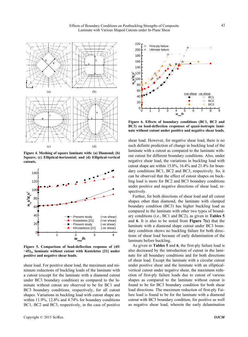
Figure 4. Meshing of square laminate with: (a) Diamond; (b) Square; (c) Elliptical-horizontal; and (d) Elliptical-vertical cutouts.
0 1 2 30
20
40
60
80
100
120
140
4
Nxy
b2 /E
2h3
wmax
/h
Present study (+ve shear) Kosteletos [21] (+ve shear) Present study (-ve shear) KKosteletos [21] (-ve shear)
Figure 5. Comparison of load-deflection response of (45/ −45)2s laminate without cutout with Kosteletos [21] under positive and negative shear loads. shear load. For positive shear load, the maximum and mi- nimum reductions of buckling loads of the laminate with a cutout (except for the laminate with a diamond cutout under BC3 boundary condition) as compared to the la- minate without cutout are observed to be for BC1 and BC3 boundary conditions, respectively, for all cutout shapes. Variations in buckling load with cutout shape are within 11.9%, 12.8% and 4.74% for boundary conditions BC1, BC2 and BC3, respectively, in the case of positive
0 1 2 3 4 5 6 7 8 90
20
40
60
80
100
120
140
160
180
200
220 First-ply failure Ultimate failure
+ve shear -ve shear BC1 BC2 BC3
Nxy
b2 /E
2h3
wmax
/h
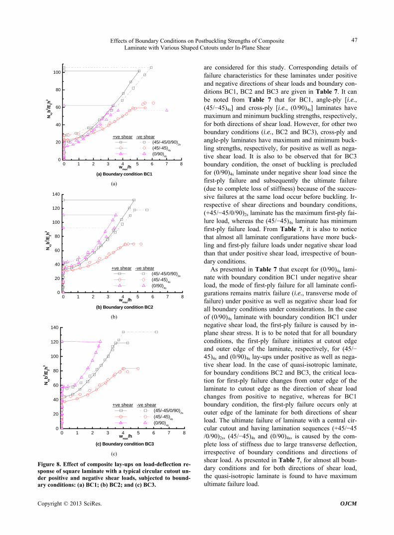
Figure 6. Effects of boundary conditions (BC1, BC2 and BC3) on load-deflection responses of quasi-isotropic lami- nate without cutout under positive and negative shear loads. shear load. However, for negative shear load, there is no such definite prediction of change in buckling load of the laminate with a cutout as compared to the laminate with- out cutout for different boundary conditions. Also, under negative shear load, the variations in buckling load with cutout shape are within 15.8%, 16.4% and 21.4% for boun- dary conditions BC1, BC2 and BC3, respectively. So, it can be observed that the effect of cutout shapes on buck- ling load is more for BC2 and BC3 boundary conditions under positive and negative directions of shear load, re- spectively.
Further, for both directions of shear load and all cutout shapes other than diamond, the laminate with clamped boundary condition (BC3) has higher buckling load as compared to the laminate with other two types of bound- ary conditions (i.e., BC1 and BC2), as given in Tables 5 and 6. It is also to be noted from Figure 7(c) that the laminate with a diamond shape cutout under BC3 boun- dary condition shows no buckling failure for both direc- tions of shear load because of early delamination of the laminate before buckling.
As given in Tables 5 and 6, the first-ply failure load is also decreased by the introduction of cutout in the lami- nate for all boundary conditions and for both directions of shear load. Except the laminate with a circular cutout under positive shear and the laminate with an elliptical- vertical cutout under negative shear, the maximum redu- ction of first-ply failure loads due to cutout of various shapes as compared to the laminate without cutout is found to be for BC3 boundary condition for both shear load directions. The maximum reduction of first-ply Fai- lure load is found to be for the laminate with a diamond cutout with BC3 boundary condition, for positive as well as negative shear load, wher in the early delamination e
Copyright © 2013 SciRes. OJCM

Effects of Boundary Conditions on Postbuckling Strengths of Composite Laminate with Various Shaped Cutouts under In-Plane Shear
44
Table 4. Verification of results.
S. No. Reference Laminate/stacking
sequence Boundary conditions
Loading conditions
Result validated In present
study In reference
Non-dimensionalized first-ply failure load i.e., Nxyb
2/E2h3
61.3 58.9 +ve shear
wmax/h at first-ply failure load 1.40 1.27
Non-dimensionalized first-ply failure load i.e., Nxyb
2/E2h3
81.9 82.6
1 Jha and
Kumara (2002)
479.88 mm × 479.88 mm × 3.72 mm plate without
cutout/(±45/0/90)2s
Simply supported on all
edges
−ve shear
wmax/h at first-ply failure load 2.39 2.42
Simply supported
on all edges+ve shear Buckling load (kN) 8.54 8.40 (8.50)b
2 Guo (2007)
320.0 mm × 320.0 mm × 2.0 mm plate with
central circular cutout of diameter 44 mm
(i.e., d/b = 0.137)/(±45)4s Clamped
on all edges+ve shear Buckling load (kN) 11.6 11.4
Non-dimensionalized buckling load i.e., Nxyb
2/E2h3
63.0 63.3 +ve shear
wmax/h at Nxyb2/E2h
3 = 70.0 1.66 1.98
Non-dimensionalized buckling load i.e., Nxb
2/E2h3
107.7 106.7
3 Kosteletosc
(1992)
279.0 mm × 279.0 mm × 2.16 mm plate without
cutout/(±45)2s
Clamped on all edges
−ve shear
wmax/h at Nxyb2/E2h
3 = 110.0 1.10 1.25
aFirst-ply failure results are based on Tsai-Hill failure criterion. bThe quantities inside and outside parentheses represent the critical buckling load (kN) from the FE analysis and experimental investigation, respectively. cKosteletos’s results presented here are extracted from the figure given in the paper.
Table 5. Details of failure characteristics of quasi-isotropic laminate with and without various shaped cutouts for boundary conditions BC1, BC2 and BC3 under positive shear load.
Boundary condition
BC1 BC2 BC3 Cutout shape
BLa/FPFb load/(wmax/h)c
FEd/FLe/ mode of
FPF
UFf load/mode
of UF
BLa/FPFb load/
(wmax/h)c
FEd/FLe/ mode of FPF
UFf load/mode of UF
BLa/FPFb load/
(wmax/h)c
FEd/FLe/mode of FPF
UFf load/mode of
UF
Without cutout
43.7/61.4/1.41 1/1/ transverseg
151.4/loss of stiffness
65.4/87.0/1.401/1/
transverseg 150.4/loss of
stiffness 83.7/102.7/1.24 1/1/transverseg
159.7/loss of stiffness
Circular 20.7/39.3/2.07 139/1/
transverse 101.9/loss of stiffness
32.7/56.5/2.031/16/
transverse 132.1/loss of
stiffness 43.9/69.2/1.85 133/1/transverse
119.0/loss of stiffness
Square 19.3/37.8/2.02 139/16/
transverse 64.5/
delamination 31.2/49.5/1.80
144/1/ transverse
73.2/ delamination
42.2/52.1/1.15 144/1/transverse 78.9/
delamination
Diamond 21.9/39.7/2.14 139/1/
transverse 40.3/
delamination 34.4/36.4/0.56
90/interface of layers 15 &
16/delamination
36.4/ delamination
-/37.3/- 90/interface of
layers 15 & 16/delamination
37.3/ delamination
Elliptical vertical
19.3/37.9/2.12 139/1/
transverse 44.5/
delamination 30.0/50.1/1.84
48/ interface of layers 15 &
16/delamination
50.1/ delamination
43.0/54.4/1.25 48/interface of
layers 15 & 16/delamination
54.4/ delamination
Elliptical horizontal
19.7/38.2/2.11 139/1/
transverse 43.1/
delamination 32.9/52.8/1.91
96/interface of layers 15 &
16/delamination
52.8/ delamination
44.3/57.1/1.34 96/interface of
layers 15 & 16/delamination
57.1/ delamination
aBuckling load; bFirst-ply failure; cNon-dimensionalized maximum transverse deflection at the first-ply failure; dFirst failed element number; eFirst failed layer number/interface of the first failed element; fUltimate failure; gTransverse mode of failure refers to the failure of lamina in a direction perpendicular to the fiber
irection due to in-plane stresses transverse to fiber direction. d
Copyright © 2013 SciRes. OJCM

Effects of Boundary Conditions on Postbuckling Strengths of Composite Laminate with Various Shaped Cutouts under In-Plane Shear
45
0 1 2 3 4 5 60
20
40
60
80
100
120
140
(a) Circular cutout
First-ply failure Ultimate failure
+ve shear -ve shear BC1 BC2 BC3
Nxy
b2 /E
2h3
wmax
/h
0.0 0.5 1.0 1.5 2.0 2.5 3.0 3.5 4.00
15
30
45
60
75
(b) Square cutout
First-ply failure Ultimate failure
+ve shear -ve shear BC1 BC2 BC3
Nxy
b2 /E
2h3
wmax
/h
0.0 0.5 1.0 1.5 2.0 2.50
10
20
30
40
50
60
(c) Diamond cutout
First-ply failure Ultimate failure
+ve shear -ve shear BC1 BC2 BC3
Nxy
b2 /E
2h3
wmax
/h
0.0 0.5 1.0 1.5 2.0 2.5 3.00
15
30
45
60
75
(d) Elliptical-vertical cutout
First-ply failure Ultimate failure
+ve shear -ve shear BC1 BC2 BC3
Nxy
b2 /E
2h3
wmax
/h
0.0 0.5 1.0 1.5 2.0 2.5 3.00
15
30
45
60
75
(e) Elliptical-horizontal cutout
First-ply failure Ultimate failure
+ve shear -ve shear BC1 BC2 BC3
Nxy
b2 /E
2h3
wmax
/h
Figure 7. Effects of boundary conditions (BC1, BC2 and BC3) on load-deflection response of quasi-isotropic laminate with: (a) Circular; (b) Square; (c) Diamond; (d) Elliptical-vertical; and (e) Elliptical-horizontal cutouts, under positive and negative shear loads. Table 6. Details of failure characteristics of quasi-isotropic laminate with and without various shaped cutouts for boundary conditions BC1, BC2 and BC3 under negative shear load.
Boundary condition
BC1 BC2 BC3 Cutout shape
BLa/FPFb load/(wmax/h)c
FEd/FLe/ mode of FPF
UFfload/ mode of UF
BLa/FPFb load/(wmax/h)c
FEd/FLe/mode of FPF
UFf load/mode of
UF
BLa/FPFb load/(wmax/h)c
FEd/FLe/ mode of FPF
UFf load/mode of
UF Without cutout
51.2/82.0/2.40 21/2/ transverseg
207.5/loss of stiffness
77.0/101.4/1.8421/2/
transverseg 149.8/loss of
stiffness 94.2/119.0/1.5
5 21/2/
transverseg 183.9/loss of
stiffness
Circular 28.3/54.8/3.10 37/2/transverse 105.8/loss of
stiffness 42.2/62.2/2.20
42/2/ transverse
117.9/loss of stiffness
54.9/65.9/1.38 108/2/
transverse 134.0/loss of
stiffness
Square 27.7/44.5/2.32 42/2/transverse 66.8/
delamination 41.7/50.7/1.39 108/2/transverse
75.2/ delamination
55.5/57.4/0.56 108/2/
transverse 78.0/
delamination
Diamond 28.5/42.3/2..29 126/interface of
layers 15 & 16/delamination
42.3/ delamination
41.9/51.1/1.54126/interfaceof layers 15 &
16/delamination
51.1/ delamination
-/49.0/- 126/interface of layers 15 &
16/delamination
49/ delamination
Elliptical vertical
24.0/46.9/2.90 54/2/transverse 47.0/
delamination 37.7/48.1/1.51 54/ 2/transverse
56.3/ delamination
43.6/61.1/1.68 54/2/
transverse 62.3/
delamination
Elliptical horizontal
24.7/46.9/2.84 84/interface of
layers 14 & 15/delamination
46.9/ delamination
35.3/47.7/1.6184/interface
of layers 14 & 15/delamination
47.7/ delamination
45.2/51.1/0.98 84/interface
of layers 13 & 14/delamination
51.1/ delamination
aBuckling load; bFirst-ply failure; cNon-dimensionalized maximum transverse deflection at the first-ply failure; dFirst failed element number; eFirst failed layer number/interface of the first failed element; fUltimate failure; gTransverse mode of failure refers to the failure of lamina in a direction perpendicular to the fiber direction due to in-plane stresses transverse to fiber direction.
takes place to cause ultimate failure before buckling. It is important to note from Table 5 that under positive shear load, the effect of cutout shape on first-ply failure load is
the least for the laminate with BC1 boundary condition (maximum variation within 4.79%) and it becomes most (maximum variation within 46.1%) for BC3 boundary
Copyright © 2013 SciRes. OJCM

Effects of Boundary Conditions on Postbuckling Strengths of Composite Laminate with Various Shaped Cutouts under In-Plane Shear
46
condition. For negative shear load, the effect of cutout shape on first-ply failure load is almost uniform for all boundary conditions (maximum variation within 25.6%).
As shown in Tables 5 and 6, irrespective of boundary conditions and loading directions, the modes of first-ply failure for the laminate with and without square and cir- cular cutouts remain the transverse mode (i.e., matrix fai- lure due to stress transverse to fiber direction). However, the first-ply failure is caused by delamination in the case of laminate with diamond and elliptical-horizontal cut-outs with boundary conditions BC2 and BC3, for both directions of shear load. Variation in first-ply failure mode with the change in shear load direction (from positive to negative) can also be observed from matrix failure to de- lamination and vice-versa, respectively, for the laminate with diamond and elliptical-horizontal cutouts under BC1 boundary condition, and for the laminate with an el- liptical-vertical cutout under BC2 and BC3 boundary con- ditions. The first-ply failure occurs at the outer edge of the laminate in the case of the laminate without cutout for all boundary conditions and for both directions of shear load. Under positive shear load, the location of the first-ply failure remains at outer edge of the laminate for all shaped cutouts for boundary condition BC1, whereas for other boundary conditions (i.e., BC2 and BC3), the first-ply failure takes place near the cutout edge for the laminate with a non-circular cutout. However, in the case of the laminate with circular cutout, it remains at outer edge of the laminate. It is important to note from Table 6 that under negative shear load, the critical location for the first-ply failure is at cutout edge only for almost all boundary conditions and all shaped cutouts.
From Tables 5 and 6, it can be noted that ultimate fail- ure load also gets reduced with the introduction of a cen- tral cutout in the laminate. Maximum reduction in ulti- mate failure load, as compared to the laminate without cutout, is observed for the laminate with a diamond shap- ed cutout and minimum reduction is found to be for the laminate with a circular cutout. This observation is true for almost all boundary conditions and for both direc- tions of shear load. It is also important to note that for positive as well as negative shear load, the effect of cut- out shape on ultimate failure load is significant for all boundary conditions. This is based on the fact that the laminate with a circular cutout bears maximum ultimate failure load, because the complete loss of stiffness is the cause of ultimate failure in this laminate; whereas in the case of laminate with other shaped cutouts, the ultimate failure load goes to minimum due to early delamination. It is to be pointed out that the material strength is utilized efficiently in the case of laminate with a circular cutout because delamination in the laminate with a circular cut- out occurs when the laminate has virtually no reserve strength due to complete loss of stiffness. It is to be noted
that for boundary condition BC1, the effect of cutout shape on ultimate failure load is same (maximum within 60.1%) for positive and negative directions of shear load, whereas for boundary conditions BC2 and BC3, this ef- fect is more (maximum within 72.2% for BC2) for posi- tive shear load than negative shear load (maximum with- in 63.4% for BC3).
It may be noted from Figures 7(a)-(e) that except the values of failure loads (i.e., first-ply failure and ultimate failure loads), the postbuckling response of the laminate with a cutout in terms of stiffness (given by the slope at a point in postbuckling range) at a particular value of ma- ximum deflection is almost the same for boundary condi- tions BC1, BC2 and BC3 irrespective of cutout shapes and directions of shear load. So, it can be concluded that there is no much effect of boundary conditions on post- buckling stiffness of the laminate with a cutout. It can also be observed from Figures 7(a)-(e) that except in the case of laminate with an elliptical (vertical and horizontal) cutout under BC3 boundary condition, although the qua- si-isotropic laminate with a cutout has more postbuckling strengths under negative shear load than that under posi- tive shear load in the early range of postbuckling for va- rious boundary conditions, but in the advance stage of postbuckling response, strengths of the laminate become larger under positive shear load than that under negative shear load and hence, it can be argued that the laminate has more postbuckling stiffness under positive shear load than that under negative shear load. In the case of lami- nate with an elliptical (vertical and horizontal) cutout un- der BC3 boundary condition, the load-deflection curves for positive and negative shear loads (i.e., postbuckling responses) almost overlap each other and hence, there is no effect of shear load directions on postbuckling stiff- ness. In addition, it is also important to mention that the effects of boundary condition on buckling, first-ply fail- ure and ultimate failure loads (given by maximum per- centage change in buckling, first-ply failure and ultimate failure loads with change in boundary condition) of the quasi-isotropic laminate with a cutout is more for posi- tive shear load than that for the negative shear load for almost all cutout shapes.
4.2. Effects of Composite Lay-Ups for Various Boundary Conditions
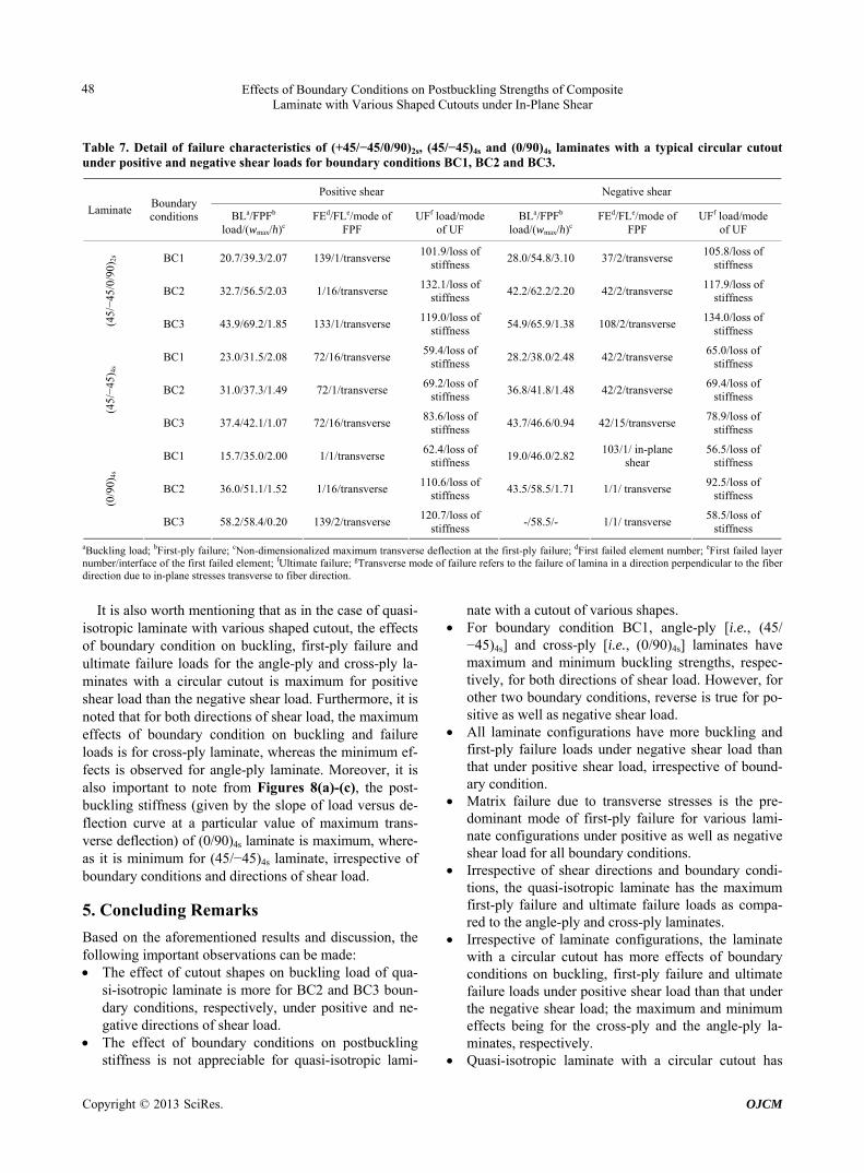
The effects of composite lay-ups on load-deflection re- sponses of square laminate with a typical central circular cutout under positive and negative shear loads is shown in Figures 8(a)-(c), respectively, for boundary conditions BC1, BC2 and BC3. Three most practical laminate con- figurations (i.e., quasi-isotropic [i.e., (+45/−45/0/90)2s], angle-ply [i.e., (45/−45)4s], and cross-ply [i.e., (0/90)4s])
Copyright © 2013 SciRes. OJCM
Effects of Boundary Conditions on Postbuckling Strengths of Composite Laminate with Various Shaped Cutouts under In-Plane Shear
47
0 1 2 3 4 5 6 70
20
40
60
80
100
8
(a) Boundary condition BC1
+ve shear -ve shear (45/-45/0/90)
2s
(45/-45)4s
(0/90)
4s
Nxy
b2 /E
2h3
wmax
/h
(a)
0 1 2 3 4 5 6 70
20
40
60
80
100
120
140
8
(b) Boundary condition BC2
+ve shear -ve shear (45/-45/0/90)
2s
(45/-45)4s
(0/90)
4s
Nxy
b2 /E
2h3
wmax
/h
(b)
0 1 2 3 4 5 6 7 80
20
40
60
80
100
120
140
(c) Boundary condition BC3
+ve shear -ve shear (45/-45/0/90)
2s
(45/-45)4s
(0/90)
4s
Nxy
b2 /E
2h3
wmax
/h
(c)
Figure 8. Effect of composite lay-ups on load-deflection re- sponse of square laminate with a typical circular cutout un- der positive and negative shear loads, subjected to bound- ary conditions: (a) BC1; (b) BC2; and (c) BC3.
are considered for this study. Corresponding details of failure characteristics for these laminates under positive and negative directions of shear loads and boundary con- ditions BC1, BC2 and BC3 are given in Table 7. It can be noted from Table 7 that for BC1, angle-ply [i.e., (45/−45)4s] and cross-ply [i.e., (0/90)4s] laminates have maximum and minimum buckling strengths, respectively, for both directions of shear load. However, for other two boundary conditions (i.e., BC2 and BC3), cross-ply and angle-ply laminates have maximum and minimum buck- ling strengths, respectively, for positive as well as nega- tive shear load. It is also to be observed that for BC3 boundary condition, the onset of buckling is precluded for (0/90)4s laminate under negative shear load since the first-ply failure and subsequently the ultimate failure (due to complete loss of stiffness) because of the succes- sive failures at the same load occur before buckling. Ir- respective of shear directions and boundary conditions, (+45/−45/0/90)2s laminate has the maximum first-ply fai- lure load, whereas the (45/−45)4s laminate has minimum first-ply failure load. From Table 7, it is also to notice that almost all laminate configurations have more buck- ling and first-ply failure loads under negative shear load than that under positive shear load, irrespective of boun- dary conditions.
As presented in Table 7 that except for (0/90)4s lami- nate with boundary condition BC1 under negative shear load, the mode of first-ply failure for all laminate confi- gurations remains matrix failure (i.e., transverse mode of failure) under positive as well as negative shear load for all boundary conditions under considerations. In the case of (0/90)4s laminate with boundary condition BC1 under negative shear load, the first-ply failure is caused by in- plane shear stress. It is to be noted that for all boundary conditions, the first-ply failure initiates at cutout edge and outer edge of the laminate, respectively, for (45/− 45)4s and (0/90)4s lay-ups under positive as well as nega- tive shear load. In the case of quasi-isotropic laminate, for boundary conditions BC2 and BC3, the critical loca- tion for first-ply failure changes from outer edge of the laminate to cutout edge as the direction of shear load changes from positive to negative, whereas for BC1 boundary condition, the first-ply failure occurs only at outer edge of the laminate for both directions of shear load. The ultimate failure of laminate with a central cir- cular cutout and having lamination sequences (+45/−45 /0/90)2s, (45/−45)4s and (0/90)4s, is caused by the com- plete loss of stiffness due to large transverse deflection, irrespective of boundary conditions and directions of shear load. As presented in Table 7, for almost all boun- dary conditions and for both directions of shear load, the quasi-isotropic laminate is found to have maximum ultimate failure load.
Copyright © 2013 SciRes. OJCM
Effects of Boundary Conditions on Postbuckling Strengths of Composite Laminate with Various Shaped Cutouts under In-Plane Shear
Copyright © 2013 SciRes. OJCM
48
Table 7. Detail of failure characteristics of (+45/−45/0/90)2s, (45/−45)4s and (0/90)4s laminates with a typical circular cutout under positive and negative shear loads for boundary conditions BC1, BC2 and BC3.
Positive shear Negative shear
Laminate Boundary conditions BLa/FPFb
load/(wmax/h)c FEd/FLe/mode of
FPF UFf load/mode
of UF BLa/FPFb
load/(wmax/h)c FEd/FLe/mode of
FPF UFf load/mode
of UF
BC1 20.7/39.3/2.07 139/1/transverse 101.9/loss of
stiffness 28.0/54.8/3.10 37/2/transverse
105.8/loss of stiffness
BC2 32.7/56.5/2.03 1/16/transverse 132.1/loss of
stiffness 42.2/62.2/2.20 42/2/transverse
117.9/loss of stiffness
(45/−
45/0
/90)
2s
BC3 43.9/69.2/1.85 133/1/transverse 119.0/loss of
stiffness 54.9/65.9/1.38 108/2/transverse
134.0/loss of stiffness
BC1 23.0/31.5/2.08 72/16/transverse 59.4/loss of
stiffness 28.2/38.0/2.48 42/2/transverse
65.0/loss of stiffness
BC2 31.0/37.3/1.49 72/1/transverse 69.2/loss of
stiffness 36.8/41.8/1.48 42/2/transverse
69.4/loss of stiffness
(45/−
45) 4
s
BC3 37.4/42.1/1.07 72/16/transverse 83.6/loss of
stiffness 43.7/46.6/0.94 42/15/transverse
78.9/loss of stiffness
BC1 15.7/35.0/2.00 1/1/transverse 62.4/loss of
stiffness 19.0/46.0/2.82
103/1/ in-plane shear
56.5/loss of stiffness
BC2 36.0/51.1/1.52 1/16/transverse 110.6/loss of
stiffness 43.5/58.5/1.71 1/1/ transverse
92.5/loss of stiffness
(0/9
0)4s
BC3 58.2/58.4/0.20 139/2/transverse 120.7/loss of
stiffness -/58.5/- 1/1/ transverse
58.5/loss of stiffness
aBuckling load; bFirst-ply failure; cNon-dimensionalized maximum transverse deflection at the first-ply failure; dFirst failed element number; eFirst failed layer number/interface of the first failed element; fUltimate failure; gTransverse mode of failure refers to the failure of lamina in a direction perpendicular to the fiber direction due to in-plane stresses transverse to fiber direction.
It is also worth mentioning that as in the case of quasi-
isotropic laminate with various shaped cutout, the effects of boundary condition on buckling, first-ply failure and ultimate failure loads for the angle-ply and cross-ply la- minates with a circular cutout is maximum for positive shear load than the negative shear load. Furthermore, it is noted that for both directions of shear load, the maximum effects of boundary condition on buckling and failure loads is for cross-ply laminate, whereas the minimum ef- fects is observed for angle-ply laminate. Moreover, it is also important to note from Figures 8(a)-(c), the post- buckling stiffness (given by the slope of load versus de- flection curve at a particular value of maximum trans- verse deflection) of (0/90)4s laminate is maximum, where- as it is minimum for (45/−45)4s laminate, irrespective of boundary conditions and directions of shear load.
5. Concluding Remarks
Based on the aforementioned results and discussion, the following important observations can be made: The effect of cutout shapes on buckling load of qua-
si-isotropic laminate is more for BC2 and BC3 boun- dary conditions, respectively, under positive and ne- gative directions of shear load.
The effect of boundary conditions on postbuckling stiffness is not appreciable for quasi-isotropic lami-
nate with a cutout of various shapes. For boundary condition BC1, angle-ply [i.e., (45/
−45)4s] and cross-ply [i.e., (0/90)4s] laminates have maximum and minimum buckling strengths, respec- tively, for both directions of shear load. However, for other two boundary conditions, reverse is true for po- sitive as well as negative shear load.
All laminate configurations have more buckling and first-ply failure loads under negative shear load than that under positive shear load, irrespective of bound- ary condition.
Matrix failure due to transverse stresses is the pre- dominant mode of first-ply failure for various lami- nate configurations under positive as well as negative shear load for all boundary conditions.
Irrespective of shear directions and boundary condi- tions, the quasi-isotropic laminate has the maximum first-ply failure and ultimate failure loads as compa- red to the angle-ply and cross-ply laminates.
Irrespective of laminate configurations, the laminate with a circular cutout has more effects of boundary conditions on buckling, first-ply failure and ultimate failure loads under positive shear load than that under the negative shear load; the maximum and minimum effects being for the cross-ply and the angle-ply la- minates, respectively.
Quasi-isotropic laminate with a circular cutout has

Effects of Boundary Conditions on Postbuckling Strengths of Composite Laminate with Various Shaped Cutouts under In-Plane Shear
49
more postbuckling stiffness under positive shear load than the laminate under negative shear load, irrespec- tive of boundary condition; and the cross-ply and an- gle-ply laminates have maximum and minimum post- buckling stiffness, respectively.
REFERENCES [1] R. M. Jones, “Mechanics of Composite Materials,” McGraw-
Hill, Kogakusha Ltd., Tokyo, 1975.
[2] S. B. Singh and D. Kumar, “Postbuckling Response and Failure of Symmetric Laminated Plates with Rectangular Cutouts under Uniaxial Compression,” Structural Engi- neering and Mechanics, Vol. 29, No. 4, 2008, pp. 455- 467.
[3] T. Özden, “Analysis of Critical Buckling Load of Lami- nated Composites Plate with Different Boundary Condi- tions Using FEM and Analytical Methods,” Computa- tional Materials Science, Vol. 45, No. 4, 2009, pp. 1006- 1015. doi:10.1016/j.commatsci.2009.01.003
[4] S. K. Panda and L. S. Ramachandra, “Buckling of Rec- tangular Plates with Various Boundary Conditions Load- ed by Non-Uniform In-Plane Loads,” International Jour- nal of Mechanical Sciences, Vol. 52, No. 6, 2010, pp. 819-828. doi:10.1016/j.ijmecsci.2010.01.009
[5] D. Kumar and S. B. Singh, “Effects of Boundary Condi- tions on Buckling and Postbuckling Responses of Com- posite Laminate with Various Shaped Cutouts,” Compos- ite Structures, Vol. 92, No. 3, 2010, pp. 769-779. doi:10.1016/j.compstruct.2009.08.049
[6] S. B. Singh and D. Kumar, “Postbuckling Response and Failure of Symmetric Laminated Plates with Rectangular Cutouts under In-Plane Shear,” Structural Engineering and Mechanics, Vol. 34, No. 2, 2010, pp. 175-188.
[7] Y. Zhang and F. L. Matthews, “Postbuckling Behaviour of Anisotropic Laminated Plates under Pure Shear and Shear Combined with Compressive Loading,” Journal of American Institute of Aeronautics and Astronautics, Vol. 22, No. 2, 1984, pp. 281-286.
[8] S. B. Singh and A. Kumar, “Postbuckling Response and Failure of Symmetric Laminates under In-Plane Shear,” Composite Science and Technology, Vol. 58, No. 12, 1998, pp. 1949-1960. doi:10.1016/S0266-3538(98)00032-3
[9] M. P. Nemeth, “Buckling and Postbuckling Behavior of Laminated Composite Plates with a Cutout,” 1996.
[10] V. O. Britt, “Shear and Compression Buckling Analysis for Anisotropic Panels with Elliptical Cutouts,” Journal of American Institute of Aeronautics and Astronautics, Vol. 32, No. 11, 1994, pp. 2293-2299.
[11] R. J. Herman, “Postbuckling Behavior of Graphite/Epoxy Cloth Shear Panels with 45˚-Flanged Lightening Holes,” M.S. Thesis, Naval Postgraduate School, Monterey, 1982.
[12] G. J. Turvey and K. Sadeghipour, “Shear Buckling of Ani- sotropic Fibre-Reinforced Rectangular Plates with Central Circular Cutouts,” Proceedings of the International Con- ference Computer Aided Design in Composite Material Technology, Southampton, 1988, pp. 459-473.
[13] S. Vellaichamy, B. G. Prakash and S. Brun, “Optimum De- sign of Cutouts in Laminated Composite Structures,” Computers & Structures, Vol. 37, No. 3, 1990, pp. 241- 246. doi:10.1016/0045-7949(90)90315-S
[14] P. N. Jha and A. Kumar, “Response and Failure of Square Laminates under Combined Loads,” Composite Structures, Vol. 55, No. 3, 2002, pp. 337-345. doi:10.1016/S0263-8223(01)00141-6
[15] P. Jain and A. Kumar, “Postbuckling Response of Square Laminates with a Central Circular/Elliptical Cutout,” Com- posite Structures, Vol. 65, No. 2, 2004, pp. 179-185. doi:10.1016/j.compstruct.2003.10.014
[16] S. J. Guo, “Stress Concentration and Buckling Behaviour of Shear Loaded Composite Panels with Reinforced Cut- outs,” Composite Structures, Vol. 80, No. 1, 2007, pp. 1-9. doi:10.1016/j.compstruct.2006.02.034
[17] S. Guo, R. Morishima, X. Zhang and A. Mills, “Cutout Shape and Reinforcement Design for Composite C-Sec- tion Beams under Shear Load,” Composite Structures, Vol. 88, No. 2, 2009, pp. 179-187. doi:10.1016/j.compstruct.2008.03.001
[18] D. Kumar and S. B. Singh, “Postbuckling Strengths of Com- posite Laminate with Various Shaped Cutouts under In- Plane Shear,” Composite Structures, Vol. 92, No. 12, 2010, pp. 2966-2978. doi:10.1016/j.compstruct.2010.05.008
[19] O. O. Ochoa and J. N. Reddy, “Finite Elements Analysis of Composite Laminates,” Kluwer Academic Publishers, Dordrecht, 1992.
[20] S. B. Singh, “Postbuckling Response, Strength and Fail- ure of Symmetric Laminates,” Ph.D. Dissertation, Indian Institute of Technology, Kanpur, 1996.
[21] S. Kosteletos, “Postbuckling Response of Laminated Plates under Shear Loads,” Composite Structures, Vol. 20, No. 3, 1992, pp. 137-145. doi:10.1016/0263-8223(92)90020-D
[22] Z. Hashin, “Failure Criteria for Unidirectional Fiber Com- posites,” Journal of Applied Mechanics, Vol. 47, No. 3, 1980, pp. 329-334. doi:10.1115/1.3153664
[23] S. W. Tsai, “A Survey of Macroscopic Failure Criteria for Composite Materials,” Journal of Reinforced Plastics and Composites, Vol. 3, No. 1, 1984, pp. 40-62. doi:10.1177/073168448400300102
Copyright © 2013 SciRes. OJCM

Effects of Boundary Conditions on Postbuckling Strengths of Composite Laminate with Various Shaped Cutouts under In-Plane Shear
50
Appendix
(1) Tsai-Hill Criterion
In this criterion a considerable interaction exists among failure strengths of the lamina as against the other non- interactive criteria such as Hashin [22] and Tsai’s [23] tensor polynomial criteria. Tensor polynomial form of the Tsai-Hill criterion can be obtained from the following most general polynomial failure criterion of Tsai [23] at failure state.
1 1 2 2 3 3 12 1 2 13 1 3 23 2 3
2 2 2 2 2 211 1 22 2 33 3 44 23 55 13 66 12
2 2 2
1
F F F F F F
F F F F F F
wherein, Fi, Fij are the strength tensors of the second and fourth rank; 1 2 3, , are the normal stress components in principal material directions 1, 2 and 3, respectively (the subscript 1 referring to the fiber direction);
12 13 23, , are the shear stress components in the planes 1 - 2, 1 - 3 and 2 - 3, respectively. In Tsai-Hill criterion the following strength tensors are used in the above ex- pression.
1 2 3 0;F F F 11 22 332 2
1 1; ;F F F 2
1;
X Y Z
44 55 662 2 2
1 1 1; ; ;F F F
R S T
12 2 2 2
1 1 1 1;
2F
X Y Z
13 2 2 2
1 1 1 1;
2F
Z X Y
23 2 2 2
1 1 1 1;
2F
Y Z X
In the above expressions X, Y and Z are the normal strengths (tensile or compressive, depending upon the sign of 1 2 3, , ) along principal material directions 1, 2 and 3, respectively; R, S and T are the shear strengths of lamina in planes 2 - 3, 1 - 3 and 1 - 2, respectively
(2) Interlaminar Failure Friterion
As per the interlaminar failure criterion, the onset of de- lamination takes place when the interlaminar transverse stress (calculated by integration of equilibrium equations) components satisfy the following expression:
2 2 23 13 23
2 1DN DS
where, 3 is the transverse normal stress component;
13 23, are the transverse shear stress components in principal material planes 1 - 3 and 2 - 3, respectively;
DN is the peel strength and DS is the interlaminar shear strength; these are taken equal to the tensile normal transverse strength and transverse shear strength (corre- sponding to the plane 1 - 3) of lamina, respectively.
Copyright © 2013 SciRes. OJCM


![STABILITY AND POSTBUCKLING BEHAVIOR OF …oden/Dr._Oden_Reprints/1973-018.stability_and.pdfstability and postbuckling behavior of space frames and shells of revolution. Gallagher [17]](https://static.fdocuments.us/doc/165x107/5e279cdacab01659037bd7a2/stability-and-postbuckling-behavior-of-odendrodenreprints1973-018stabilityandpdf.jpg)
