
Organic Bedding, Organic Bamboo Comforters, Bamboo Bedding, Silk Pillow

Journal of Engineering Volume 23 January 2017 Number 1
136
Effects of Bedding Types on the Behavior of Large Diameter GRP Flexible
Sewer Pipes
ABSTRACT
Flexible pipes, such as GRP pipes, serve as effective underground infrastructure especially as
sewer pipeline. This study is an attempt for understanding the effects of bedding types on the
behavior of large diameter GRP flexible sewer pipes using three dimensional finite element
approaches. Theoretical and numerical analyses were performed using both BS EN 1295-1
approach and finite element method (ABAQUS software). The effects of different parameters are
studied such as, depth of backfill, bedding compaction, and backfill compaction. Due to
compaction, an increase in the bedding compaction modulus (E’1) results in a reduction of both
stresses and displacements of the pipe, especially, for well compacted backfill. An increase of
(E’1) from 14MPa to 30MPa results in a reduction in stresses 40% and about 25% in
displacements. Maximum reductions in stresses were found to be about 25% only while the
reduction in displacement was found to be less than 10%. As backfill material compaction
modulus (E’2) is increased from 14MPa to 40MPa, a maximum reduction in stresses within the
pipe was found to be not less than 60% while the displacement reduces up to 65%. Key words: Flexible Pipes; GRP Pipes, Bedding Compaction, Backfill Compaction, ABAQUS
GRP تاثيراث أوواع طبقت الفرش على تصرف أوابيب المجاري المروت راث الأقطار الكبيرة مه ووع
الخلاصت
انطسج ي خطط ااتة انثى انرحرح انفعانح خصصا" ف خطط أاتة GRPذعرثشالأاتة انشح كأاتة
أاتة انجاسي انشح راخ الأقطاس انكثشج ي ع أاع انفشش عهى سهك ذأثشاخفى ن يحانح انذساسحز .انجاسي
GRP ي أجشد انرحهلاخ انظشح انعذدح تاسرخذاو كمحث . ظشح انعاصش انحذدج ثلاثح الأتعادتاسرخذاو(BS EN
ذى دساسح ذأثشعذج يرغشاخ يثلا":عق .(ABAQUSيجا)تش تأسرخذاو ثلاثحالأتعاد طشقحانعاصشانحذدج (1-1295
رج اخفاض فا ’E)1(تسثة انضادج ف حذل يادج انفشش يادج انذف. سصيادج انفشش ذحد الأثب سصيادج انذف ,
14MPaي ’E)1(ف كم ي الأجاداخ انرشاخ ف الاثب, خصصا" عذيا ذك ذشتح انذف يحذنح جذا". صادج
ف انرشاخ. اكثش اخفاض ف الاجاداخ حان %25حان %40رج اكثش اخفاض ف الاجاداخ ب 30MPaانى
فا 40MPaانى 14MPaضداد ي ’E)2(عذيا سص يادج انذف .%10فقط تا الاخفاض ف انرشاخ اقم ي 25%
.%65تا انرشاخ ذقم تاكثش ي %60اكثش اخفاض ف الاجاداخ خلال الاثب ك اكثش ي
ABAQUS , سص يادج انفشش, سص يادج انذف , تشايجGRPانشح,ااتة الااتةالكلماث الرئيسيت:
Dr. Adnan Falih Ali Professor
College of Engineering, University of Baghdad
Email: [email protected]
Raad Abdulkhudhur Sehaib
Assistant Lecturer
Engineering of Building and Construction,
University of Technology
Email: [email protected]
د. عذوان فالح عل اسرار
سح/جايعح تغذادكهح انذ قسى انذسح انذح
رعذ عبذالخضر سحيب
يذسط يساعذ
انجايعح انركنجح-قسى ذسح انثاء الاشاءاخ

Journal of Engineering Volume 23 January 2017 Number 1
137
1. INTRODUCTION
Buried pipes for sewer systems are usually subjected to external forces caused by backfill and
additional surcharge due to traffic loading. Accordingly, stresses within the pipe walls will be
developed, those stresses are assumed to be depending on the type of backfill, depth of backfill
and the bedding type in additional to pipe diameter. The present paper presents a theoretical
investigation of the behavior of large diameter sewer pipes made of (GRP) when buried at
different depths, moreover, the study presents the effect of bedding type on the developed
stresses, strains and displacements of the pipe walls using finite elements analysis implemented
in the ready software ABAQUS.
2. OBJECTIVES
The main objectives of the current work are:
(a) To provide a comparative analysis of flexible sewer pipes taking into account variation of
the following factors,
Depths of the pipes variation relative to the pipe diameter.
Properties of the soil used to backfill above the pipe.
(b) To study the effect of bedding type on the behavior of flexible sewer pipes
(c) To present numerical case studies by implementing the finite element procedure so as to
provide a more accurate behavior of the flexible pipe and to compare the results with the
available procedure currently in use to assess the pipe behavior.
3. ANALYTICAL APPROACH of (BS EN 1295-1)
An analytical method is recommended in UK by [BS EN 1295-1], and is summarized in the
following steps:
3.1 Soil Modulus
Soil modulus is the parameter of the most influence on the structural calculation, as soil stiffness
will generally be significantly greater than the pipe stiffness. Spangler modulus values have been
determined from empirical measurements and are indicated in Tables 1 for the native soil. The
soil modulus adjustment factor (CL), is used to take into account the influence of native soil
properties on the overall soil modulus (E’), and can be calculated by using Eq.(1) as shown
below: [“Design and Installation Manual of Ridgidrain, Ridgisewer and Polysewer”].
⁄
[ ⁄ ](
⁄ ) [ ⁄ ] (1)
E’= E
’2 CL (2)
3.2 Vertical Soil Pressure (Pe)
The vertical dead load applied to the pipe system is typically restricted to the soil pressure
generated by the pipe backfill material. The load is taken as the pressure imposed by the prism of
soil directly overlying the pipe. No allowance is made within the available standards for the
effect of shear between the backfill material and the trench walls. Where the density of the
backfill material is not available, (value of 19.6kN/m3) may be assumed for design purposes.
Pe= (3)

Journal of Engineering Volume 23 January 2017 Number 1
138
3.3 Surcharge Pressure (Ps)
The imposed pressure from vehicle traffic is largely dependent on the depth of cover above the
pipe. Surcharge loads are calculated using Boussinesq’s theory which is plotted in Fig.1
3.4 Deflection Lag Factor (DL)
An empirical factor is used to account for relaxation, or creep, of the pipe/soil system and other
general long-term settlement effects. A conservative design approach is taken by assuming no
beneficial effect is derived from frictional forces between the trench walls and backfill material,
in addition to the use of a long-term pipe stiffness parameter. Values generally range from 1.0 to
1.5, dependant on the type of pipe surround used and its level of compaction. A well installed
gravity flow pipe, utilising a single sized granular bed and surround, a value of 1.0 is typically
taken for the deflection lag factor.
3.5 Deflection Coefficient (KX)
A bedding factor is used to represent the extent of lateral support provided by the pipe bedding.
For pipes receiving support over the full 180° lower half of the pipe a value of 0.083 should be
used, whereas bedding providing only a line load support, a value of 0.100 would be more
appropriate.
3.6 Pipe Deformation
The deformation of flexible pipes under load results in the ovalization of the pipe (a reduction in
the vertical diameter and an increase in the horizontal diameter). As the horizontal diameter of
the pipe increases, it derives support from the sidefill and trench wall. This passive earth pressure
increases as the pipe deforms further until the pipe-soil system comes into equilibrium.
Ovalization can be calculated using Eq. (4) as shown below:
[ ]
(4)
3.7 Buckling Resistance of Buried Pipeline
The buckling resistance of buried, flexible non-pressurized pipelines is a combination of the
pipes inherent buckling resistance and support afforded by the pipe surround. The critical
buckling pressure of a buried pipe is substantially greater than that for unrestrained pipes subject
to external loading. Bending stress can be calculated by using Eq. (5) as shown below:
bs =E Df (
) (
) (5)
4. FINITE ELEMENT MODEL Numerical applications using Finite Element Analyses are carried out to assess the behavior of
buried pipes in trench installations. In the numerical analyses, effects of pipe material, height of
fill above the pipe, soil properties are investigated. In the current study, effects of bedding types
on the behavior of large diameter GRP flexible sewer pipes are studied by using FE. The FE
analyses were carried out using ABAQUS, [Hibbitt, Abaqus Manual,( 2009)], program in
addition to the analysis based on the traditional procedure used for structural design of buried
pipelines which is used under various conditions of loading [BSI. 1295-1] ,British
Standard,1998.

Journal of Engineering Volume 23 January 2017 Number 1
139
Each of the above mentioned parameters was varied within an acceptable practical range and the
corresponding results of stresses and deformations have been calculated numerically to explain
the global response, as follows:
o Pipe diameter is equal to (3 m).
o Trench width is equal to (4 m).
o Depths of the pipes are varied such that the soil depth above the pipe equals to:
Pipe outside diameter (m).
Pipe outside diameter +1.5 m.
Pipe outside diameter +3 m.
o Properties of the soil surrounding the pipe and the bedding material were varied such
that:
Bedding Soil Modulus, E’1, of bedding material to have values of 14, 20 and 30MN/m2.
Embedment Soil Modulus, E’2, of backfill material to have values of 14, 30 and 40
MN/m2.
Native Soil Modulus, E’3, to have values of 14, 20 and 30MN/m2.
The three-dimensional finite element models of pipe-soil interaction were performed by using,
ABAQUS, version 6.10-1, computer program. The finite element method is one of the most
popular numerical methods used for obtaining an approximate solution for complex problems in
various fields of engineering.
The flexible sewer pipeline model including five steps following:
4.1 Types of Loads on a Pipeline
The design and analysis of buried flexible pipelines are carried out for the total loads, comprising
the effects of the dead load exerted by soil and the live load caused by traffic.
Both, dead and live loads acting directly on the pipeline are assumed vertical and of static nature
acting on the pipeline.
4.1.1 Dead Load
The weight of soil, which is generally called dead load, is calculated using ABAQUS program.
ABAQUS calculates the loading using the acceleration magnitude that one may enter in the
gravity load definition and the density is specified in the material definition.
Unit weight (kN/m3) = Mass density (kg/m
3) Gravity load (9.81m/sec
2) (6)
The dead load on the buried pipeline is normally substantially greater than the live load because
the effects of live load, usually due to traffic, diminish rapidly with depth of soil above the pipe.
4.1.2 Live Load
The pressure exerted on pipelines by concentrated surface surcharges, such as vehicle wheels,
construction vehicles, or track railway, are generally called live load.
HS Loadings
The HS loadings are illustrated in Fig.2. They consist of a tractor truck with semi-trailer or of the
corresponding lane loading. The HS loadings are designated by the letters HS followed by a
number indicating the gross weight in tons of the tractor truck. The variable axle spacing has
been introduced in order that the spacing of axles may approximate more closely the tractor
trailers now in use. The variable spacing also provides a more satisfactory loading for continuous

Journal of Engineering Volume 23 January 2017 Number 1
140
spans, in that heavy axle loads may be so placed on adjoining spans as to produce maximum
negative moment, [The American Association of State Highway and Transportation
Officials, (2002)].
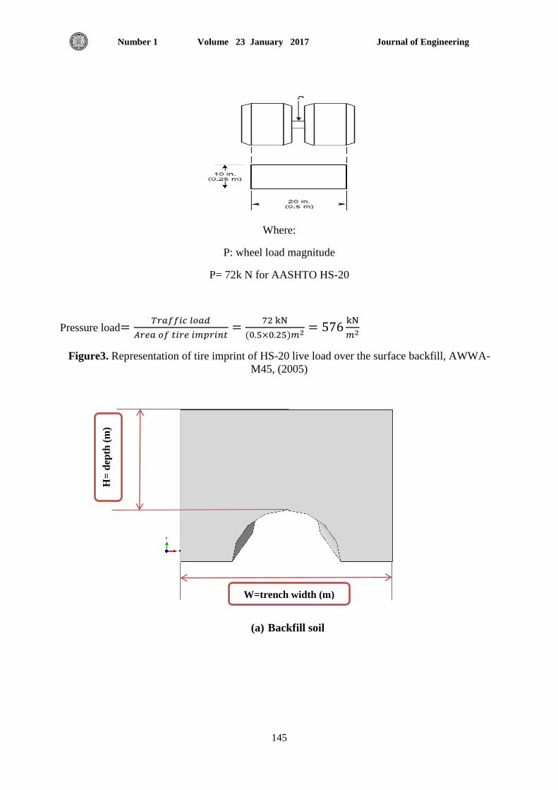
Traffic load is represented as a rectangle area over the surface backfill as shown in Fig.3 in
ABAQUS program.
4.2 Material Properties
4.2.1 Soil Properties
There exist several types of soils: clay, sand, rock, undistributed granular soils, placed granular
soils and compacted backfill ground around buried pipelines placed in an excavated trench.
In this study, the soil is divided into two types: bedding and backfill soils. The types of soil and
their mechanical properties are shown in Table 2
4.2.2 Pipeline Properties Large diameter fiberglass reinforced plastic (GRP) pipelines which are used for trunk sewer
construction or sewer networks are assumed to possess the properties shown in Table 3.
4.3 Models of the Soil and the Pipeline
In this study, the finite element models of the pipeline and the soils are established using the
package ABAQUS to carry out the analysis of flexible buried pipelines. In the ABAQUS
program, the soil model is defined as a three-dimensional (3D) deformable solid body and elastic
characterised, which is divided into two types: bedding and backfill soils as shown in Fig.4.
On the other hand the pipeline is simulated as a three-dimensional (3D) deformable shell model
as shown in Fig.5.
4.4 Surfaces of the Soil and the Pipeline
Definition surfaces of the soil and pipeline to generate contact interaction between the parts of
the model. The limits of each type are shown in Fig.6 and Fig.7.
4.5 Assembly of Pipeline and Soil A physical model is typically created by assembling various components. The assembly interface
in ABAQUS allows analysts to create a finite element mesh using an organizational scheme that
parallels the physical assembly. In ABAQUS, the components that are assembled together are
called part instances. An assembly is a collection of positioned part instances of soil and pipeline
as shown in Fig.8. An analysis is conducted by defining boundary conditions, constraints,
interactions, and a loading history for the assembly.
4.6 Interaction between the Soil and a Pipeline
In ABAQUS, the types of constraints include tie, rigid body, display body, coupling, MPC
(Multi- Point Constraint), shell-to-solid coupling, embedded region and equation. A tie
constraint ties two separate surfaces together so that there is no relative motion between them.
One constraint (called tie) is adopted for simplicity to connect bedding top surface and backfill
bottom surface, backfill surface and pipeline top surface as well as bedding surface and pipeline
bottom surface, which are fully bonded to each other as shown Fig.9.
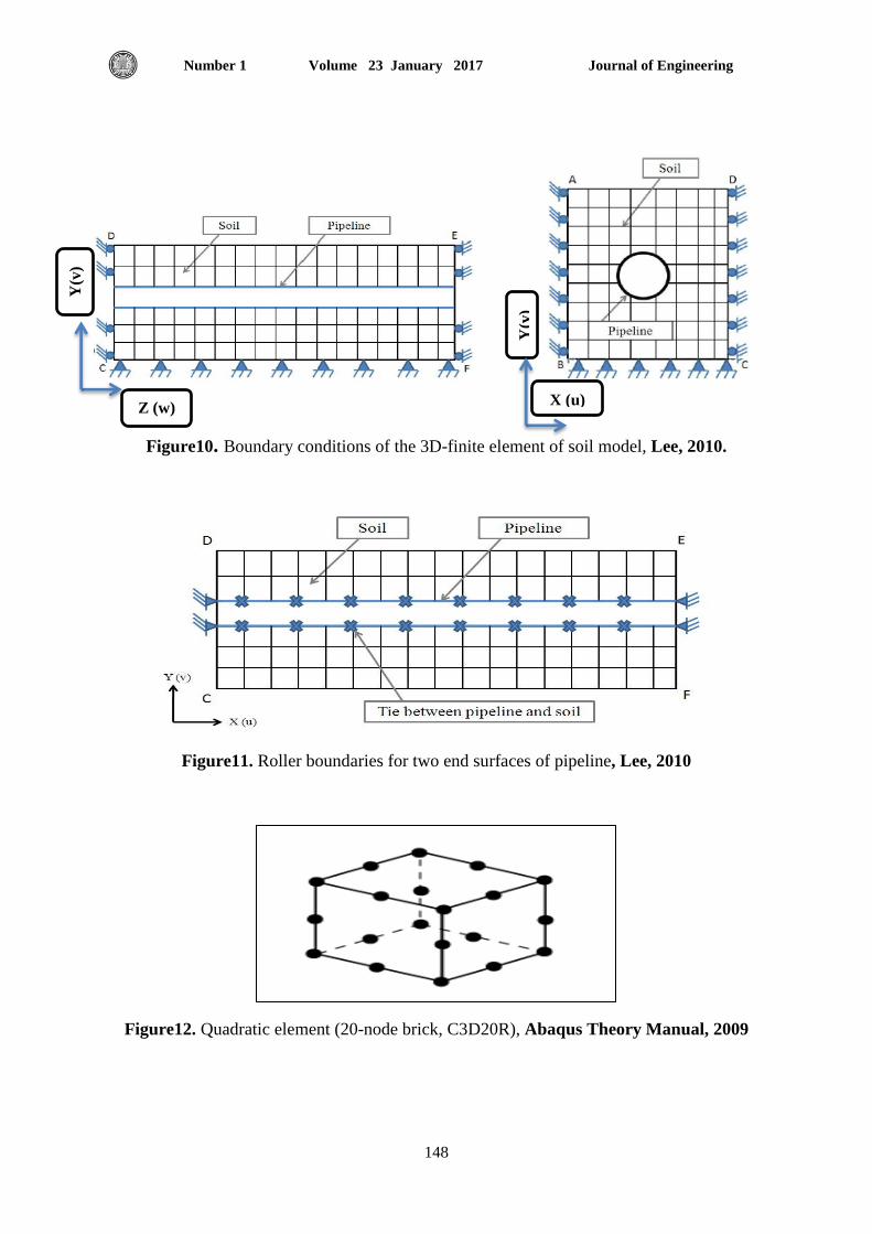
4.7 Boundary Conditions In a 3D-finite element model related to soil and pipeline, two boundary conditions of 3D- finite
element soil model need to be considered; bottom surface and four side surfaces of 3D-finite
Journal of Engineering Volume 23 January 2017 Number 1
141
element soil model whereas 3D-finite element pipeline model, boundary conditions need to be
considered at two end surfaces of a pipeline and circumferential pipeline surface which comes
into contact with soil.
4.7.1 Boundary Condition of Soil’s 3D-Finite Element Model First, the four side surfaces (left, right, front, and back) of the 3D-finite element soil model are
supposed to be on rollers as shown in Fig.10 since these surfaces for left, right, front, and back
restrain only the horizontal movement (i.e. u = w = 0).. Additionally, the bottom surface of the
3D-FE soil model is proposed to be completely fixed (i.e. u = v = w = 0) in order to restrain
horizontal (i.e. u = w = 0) and vertical movement (i.e. v= 0). This is because the bottom
boundary is selected at the known location of a bedrock surface, Rao, (1999).
4.7.2 Boundary Condition of Pipeline’s 3D-Finite Element Model Boundary condition of proposed of 3D-finite element pipeline model is shown in Fig.11; Two
end surfaces of the pipeline and surrounding the pipeline surface come into contact with soil.
4.8 Element Types Under the comprehensive consideration of buried pipelines, the 3D reduced integration
continuum brick element with twenty nodes with a second-order (or quadratic) interpolation,
C3D20R was selected for the (bedding and backfill) soils as shown in Fig.12.
The (3D) reduced shell continuum element with eight nodes with a second-order (or quadratic)
interpolation, S8R was selected for the pipeline as shown in Fig.13.
The second-order elements are more effective than the first-order elements because the second-
order elements can deal with bending dominant problems which cannot be solved by the first-
order elements, Lee, (2010).
4.9 Defining Loads In ABAQUS, self-weights of both soil and pipelines are represented as gravity loads, while the
traffic load is represented as a pressure load over the surface backfill as shown in Fig.14.
4.10 Meshing both Soil and Pipeline Model The mesh module contains tools that allow ABAQUS/CAE to generate a finite element mesh on
created models. Various levels of automation and control are available so that a mesh is
produced. The mesh is the step related to dividing the models into lots of small parts. These
divided 3D small meshed elements in models play an important role to offer suitable results in
accordance with the chosen number of elements and the type of element as shown in Fig.15.
4.11 Creating an Analysis Job
Once all of the tasks involved in defining the model are finished, it is necessary to use job
module for analysing the created model. The job module allows ABAQUS/CAE to interactively
submit a job for analysis and monitor its progress.
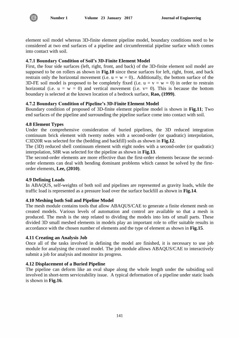
4.12 Displacement of a Buried Pipeline
The pipeline can deform like an oval shape along the whole length under the subsiding soil
involved in short-term serviceability issue. A typical deformation of a pipeline under static loads
is shown in Fig.16.

Journal of Engineering Volume 23 January 2017 Number 1
142
4.13 Stresses in GRP Pipelines
The maximum longitudinal stress has been computed from the general elastic static analysis. The
static loads, which are simulated vertically, caused the pipeline to be deformed into an oval
shape and allowed the maximum longitudinal stress of a buried pipeline to occur at both the crest
and the invert of a pipeline as shown in Fig.17.
It is possible to conclude that the generated maximum stress of a pipeline at both crest and invert
of the pipeline makes the flexible pipeline to buckle at these positions of the pipeline. This
means that if there is not enough strength of a pipeline for resisting static loads, the buckling will
be generated at both the crest and the invert of a pipeline and the flexible pipeline will totally
collapse when stresses reaches a critical buckling level.
5. NUMERICAL RESULTS AND DISCUSSIONS OF CASE STUDIES
Using the procedure adopted in the previous section, parametric studies are carried out and
presented in the current section, and these parametric studies take into consideration variation of
several parameters as follows:
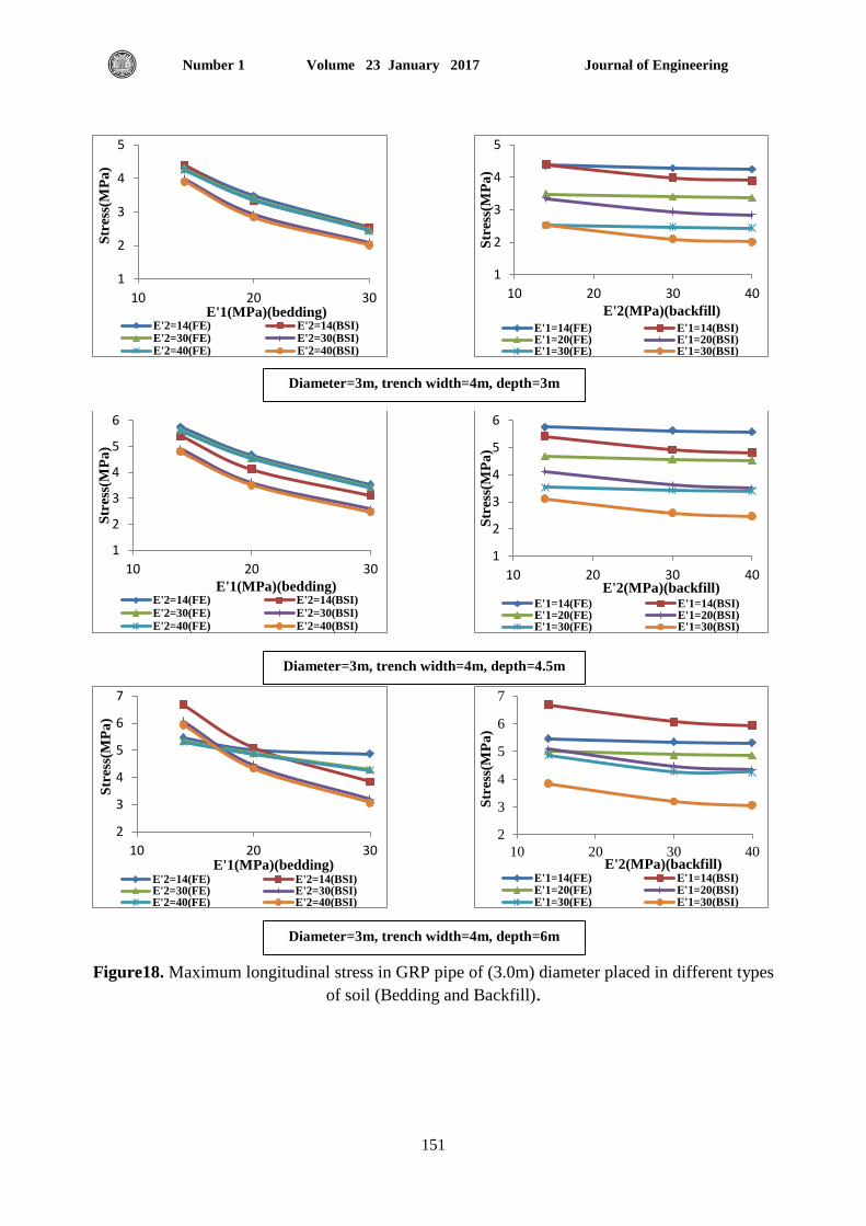
5.1 Effect of Bedding and Backfill
Under various bedding and backfill conditions, when examining the analysis results given in Fig.
18 to 19 it can be noted that:
1. Bedding compaction was found to be of important influence on both stresses and
displacements of the pipe irrespective of pipe diameter as predicted by the (FE) approach.
It was also found that increasing bedding compaction (E’1) results in a reduction of both
stresses and displacements of the pipe, especially, for well compacted backfill. This
behavior is attributed to the tendency of rigid behavior of the pipe, the underneath, and
surrounding materials. An increase of (E’1) from 14MPa to 30MPa results in a maximum
reduction in stresses by 40% and to about 25% in displacements.
2. If the backfill material (E’2) is loose, bedding compaction was found to be effective
mainly in cases of shallow pipes where the stresses still reduce with compaction but the
displacements were found to be less affected. Maximum reductions in stresses were
found to be about 25% only while the reduction in displacement was found to be less
than 10%.
3. The procedure suggested by the (BSI) were found to lead to results which are close to
those predicted by the (FE) in the following cases
Well and very well compacted bedding (E’1 20 MPa)
Relatively narrow trenches as compared to the pipe diameters
Well compacted backfill surrounding pipes of relatively small diameters
However, displacements of the pipes as predicted by the FE approach were found
to be close to those predicted by the BSI approach in cases of well compacted
bedding and backfill for pipes of medium and small diameters.
This behavior is related to the increase in angle of repose of the backfill materials which results
almost in a solid medium behavior which is assumed by both the FE and the BSI procedure.
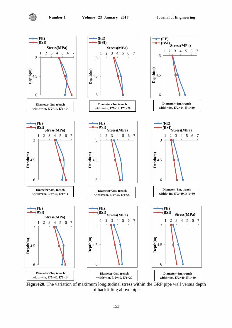
5.2 Effect of Depth of Backfill
From Fig.20 and Fig.21,the maximum longitudinal stress of GRP pipe increases with depth
increasing for bedding soil modulus (E’1) 14, 20 and 30MPa and for backfill soil modulus (E’2)
14, 30 and 40MPa. Also The maximum vertical displacement of GRP pipe increases with depth

Journal of Engineering Volume 23 January 2017 Number 1
143
increasing for bedding soil modulus (E’1) 14, 20 and 30MPa and for backfill soil modulus (E’2)
14, 30 and 40MPa.
6. CONCLUSIONS AND RECOMMENDATIONS
6.1 Conclusions
1. The stresses and deformations within the pipe walls increase with pipe depth below the ground
surface, however, the rate of increase in stresses and deformations becomes less as the depth
exceeds 2 times the diameter due to the increase in the arch action.
2. The stresses within the pipe were found to maintain constant values or slightly decrease with
the increase of trench width.
3. In cases of loose bedding materials, displacements within the pipe were found to reduce with
the increase of trench width, especially in cases of deep pipes.
6.2 Recommendations
1. A study on the flexible sewer pipes in underground water should be made.
2. Effects of seismic load on buried pipeline are another topic for future study.
REFERENCES
Hibbitt, Karlsson and Sorenson, 2009, Abaqus Theory Manual, Version, Inc., INC
Design and Installation Manual of Ridgidrain, Ridgisewer and Polysewer. Available
at,(www. Polypipe Civils.co.uk.).
The American Association of State Highway and Transportation Officials, (2002).
AWWA (American Water Works Association), 2005,”Fiberglass Pipe Design”, M45,
Second Edition
British Standard, 1998,” Structural design of buried pipelines under various conditions of
loading”, BS EN 1295-1
Lee, H., 2010," Finite element analysis of a buried pipeline", M.Sc. Thesis, University of
Manchester, School of Mechanical, Aerospace, and Civil Engineering
RAO, S. S., 1999, “The Finite Element Method in Engineering”, Boston, Butterworth-
Heinemann.
NOMENCLATURE
CL: Soil Modulus Adjustment Factor
D: Mean Diameter of Pipe
Df : Strain Factor
DL: Deflection Lag Factor
E’: Average Values of Modulus of Soil Reaction
E’1: Bedding Soil Modulus
E’2: Embedment Soil Modulus (Backfill)
E’3: Native Soil Modulus
KX: Deflection Coefficient (Bedding Constant)
Pe: Vertical Soil Pressure, kN/m2
PS: Surcharge Pressure, kN/m2
S22: Maximum Longitudinal Stress, N/m2
t: Thickness of the Pipe Wall, mm
U: Vertical Displacement

Journal of Engineering Volume 23 January 2017 Number 1
144
Pipe Deflection
: Unit Weight of Soil, kN/m3.
bs : Bending Stress in Pipe Wall
ABAQUS/CAE: Complete Abaqus Environment
AWWA: American Water Works Association
Figure1. Surcharge pressure Ps due to vehicle wheels, British standard, (1998).
Figure2. Standard HS trucks, the American Association of State Highway and Transportation
Officials, (2002).
Journal of Engineering Volume 23 January 2017 Number 1
145
Where:
P: wheel load magnitude
P= 72k N for AASHTO HS-20
Pressure load
Figure3. Representation of tire imprint of HS-20 live load over the surface backfill, AWWA-
M45, (2005)
(a) Backfill soil
H=
dep
th (
m)
W=trench width (m)

Journal of Engineering Volume 23 January 2017 Number 1
146
(b)Bedding soil
Figure4. Soil model in ABAQUS program
Figure5. Pipeline model in ABAQUS program
Figure6. Limits of bedding and backfill soils
D/4
W=trench width (m)
Bedding top surfaces
Bedding surface
Backfill bottom surfaces
Backfill surface

Journal of Engineering Volume 23 January 2017 Number 1
147
Figure7. Surfaces of a pipeline
Figure8. Assembly of pipeline and soil
Figure9. Interaction between the soil and a pipeline
Pipeline top surface
Pipeline bottom surface
Backfill
Bedding
Pipeline
Tie between bedding
top and backfill bottom
surfaces
Tie between bedding surface
and pipeline bottom surface
Tie between backfill surface
and pipeline top surface
Journal of Engineering Volume 23 January 2017 Number 1
148
Figure10. Boundary conditions of the 3D-finite element of soil model, Lee, 2010.
Figure11. Roller boundaries for two end surfaces of pipeline, Lee, 2010
Figure12. Quadratic element (20-node brick, C3D20R), Abaqus Theory Manual, 2009
Y(v
)
Z (w)
Y(v
)
X (u)

Journal of Engineering Volume 23 January 2017 Number 1
149
Figure13. Shell element (8-node shell, S8R), Abaqus Theory Manual, 2009
Figure14. Representation of loads on assembly of soil and pipeline models
(a) Bedding Model (b) Backfill Model
Pressure load
Gravity load

Journal of Engineering Volume 23 January 2017 Number 1
150
(c) Pipeline Model (d) Assembly Model
Figure15. Meshing of soil and pipeline
Figure16. Deformations of GRP pipelines
Figure17. Stresses in GRP pipelines
Journal of Engineering Volume 23 January 2017 Number 1
151
Figure18. Maximum longitudinal stress in GRP pipe of (3.0m) diameter placed in different types
of soil (Bedding and Backfill).
1
2
3
4
5
10 20 30
Str
ess(
MP
a)
E'1(MPa)(bedding) E'2=14(FE) E'2=14(BSI)E'2=30(FE) E'2=30(BSI)E'2=40(FE) E'2=40(BSI)
1
2
3
4
5
10 20 30 40
Str
ess(
MP
a)
E'2(MPa)(backfill)
E'1=14(FE) E'1=14(BSI)E'1=20(FE) E'1=20(BSI)E'1=30(FE) E'1=30(BSI)
1
2
3
4
5
6
10 20 30
Str
ess(
MP
a)
E'1(MPa)(bedding) E'2=14(FE) E'2=14(BSI)E'2=30(FE) E'2=30(BSI)E'2=40(FE) E'2=40(BSI)
1
2
3
4
5
6
10 20 30 40
Str
ess(
MP
a)
E'2(MPa)(backfill) E'1=14(FE) E'1=14(BSI)E'1=20(FE) E'1=20(BSI)E'1=30(FE) E'1=30(BSI)
2
3
4
5
6
7
10 20 30
Str
ess(
MP
a)
E'1(MPa)(bedding) E'2=14(FE) E'2=14(BSI)E'2=30(FE) E'2=30(BSI)E'2=40(FE) E'2=40(BSI)
2
3
4
5
6
7
10 20 30 40
Str
ess(
MP
a)
E'2(MPa)(backfill) E'1=14(FE) E'1=14(BSI)E'1=20(FE) E'1=20(BSI)E'1=30(FE) E'1=30(BSI)
Diameter=3m, trench width=4m, depth=3m
Diameter=3m, trench width=4m, depth=4.5m
Diameter=3m, trench width=4m, depth=6m

Journal of Engineering Volume 23 January 2017 Number 1
152
Figure19. Maximum vertical displacement in GRP pipe of (3.0m) diameter placed in different
types of soil (Bedding and Backfill).
6
9
12
15
18
21
24
10 20 30
dis
pla
cem
ent(
mm
)
E'1(MPa)(bedding) E'2=14(FE) E'2=14(BSI)E'2=30(FE) E'2=30(BSI)E'2=40(FE) E'2=40(BSI)
6
9
12
15
18
21
24
10 20 30 40
dis
pla
cem
ent(
mm
)
E'2(MPa)(backfill E'1=14(FE) E'1=14(BSI)E'1=20(FE) E'1=20(BSI)E'1=30(FE) E'1=30(BSI)
5
10
15
20
25
30
10 20 30
dis
pla
cem
ent(
mm
)
E'1(MPa)(bedding) E'2=14(FE) E'2=14(BSI)E'2=30(FE) E'2=30(BSI)E'2=40(FE) E'2=40(BSI)
5
10
15
20
25
30
10 20 30 40
dis
pla
cem
ent(
mm
)
E'2(MPa)(backfill)
E'1=14(FE) E'1=14(BSI)E'1=20(FE) E'1=20(BSI)E'1=30(FE) E'1=30(BSI)
15
20
25
30
35
40
10 20 30
dis
pla
cem
ent(
mm
)
E'1(MPa)(bedding) E'2=14(FE) E'2=14(BSI)E'2=30(FE) E'2=30(BSI)E'2=40(FE) E'2=40(BSI)
15
20
25
30
35
40
10 20 30 40
dis
pla
cem
ent(
mm
)
E'2(MPa)(backfill) E'1=14(FE) E'1=14(BSI)E'1=20(FE) E'1=20(BSI)E'1=30(FE) E'1=30(BSI)
Diameter=3m, trench width=4m, depth=3m
Diameter=3m, trench width=4m, depth=4.5m
Diameter=3m, trench width=4m, depth=6m
Journal of Engineering Volume 23 January 2017 Number 1
153
Figure20. The variation of maximum longitudinal stress within the GRP pipe wall versus depth
of backfilling above pipe
3
4.5
6
1 2 3 4 5 6 7
Dep
th(m
)
Stress(MPa)
(FE)(BSI)
3
4.5
6
1 2 3 4 5 6 7
Dep
th(m
)
Stress(MPa)
(FE)(BSI)
3
4.5
6
1 2 3 4 5 6 7
Dep
th(m
)
Stress(MPa)
(FE)(BSI)
3
4.5
6
1 2 3 4 5 6 7
Dep
th(m
)
Stress(MPa)
(FE)(BSI)
3
4.5
6
1 2 3 4 5 6 7
Dep
th(m
)
Stress(MPa)
(FE)(BSI)
3
4.5
6
1 2 3 4 5 6 7
Dep
th(m
)
Stress(MPa)
(FE)(BSI)
3
4.5
6
1 2 3 4 5 6 7
Dep
th(m
)
Stress(MPa)
(FE)(BSI)
3
4.5
6
1 2 3 4 5 6 7
Dep
th(m
)
Stress(MPa)
(FE)(BSI)
3
4.5
6
1 2 3 4 5 6 7
Dep
th(m
)
Stress(MPa)
(FE)(BSI)
Diameter=3m, trench
width=4m, E’2=14, E’1=14
Diameter=3m, trench
width=4m, E’2=14, E’1=20
Diameter=3m, trench
width=4m, E’2=14, E’1=30
Diameter=3m, trench
width=4m, E’2=30, E’1=14 Diameter=3m, trench
width=4m, E’2=30, E’1=20
Diameter=3m, trench
width=4m, E’2=30, E’1=30
Diameter=3m, trench
width=4m, E’2=40, E’1=14
Diameter=3m, trench
width=4m, E’2=40, E’1=20
Diameter=3m, trench
width=4m, E’2=40, E’1=30

Journal of Engineering Volume 23 January 2017 Number 1
154
Figure21. The variation of maximum vertical displacement (deformation) within the GRP pipe
wall versus depth of backfilling above pipe
3
4.5
6
10 15 20 25 30 35 40
Dep
th(m
)
displacement(mm)
(FE)(BSI)
3
4.5
6
10 15 20 25 30 35 40
Dep
th(m
)
displacement(mm)
(FE)(BSI)
3
4.5
6
10 15 20 25 30 35 40
Dep
th(m
)
displacement(mm)
(FE)(BSI)
3
4.5
6
10 15 20 25 30 35 40
Dep
th(m
)
displacement(mm)
(FE)(BSI)
3
4.5
6
10 15 20 25 30 35 40
Dep
th(m
)
displacement(mm)
(FE)(BSI)
3
4.5
6
10 15 20 25 30 35 40
Dep
th(m
)
displacement(mm)
(FE)(BSI)
3
4.5
6
10 15 20 25 30 35 40
Dep
th(m
)
displacement(mm)
(FE)(BSI)
3
4.5
6
5 10 15 20 25 30 35 40
Dep
th(m
)
displacement(mm)
(FE)(BSI)
Diameter=3m, trench
width=4m, E’2=14, E’1=14
Diameter=3m, trench
width=4m, E’2=14, E’1=20
Diameter=3m, trench
width=4m, E’2=14, E’1=30
Diameter=3m, trench
width=4m, E’2=30, E’1=14 Diameter=3m, trench
width=4m, E’2=30, E’1=20
Diameter=3m, trench
width=4m, E’2=30, E’1=30
3
4.5
6
10 15 20 25 30 35 40
Dep
th(m
)
displacement(mm)
(FE)(BSI)
Diameter=3m, trench
width=4m, E’2=40, E’1=14
Diameter=3m, trench
width=4m, E’2=40, E’1=20
Diameter=3m, trench
width=4m, E’2=40, E’1=30

Journal of Engineering Volume 23 January 2017 Number 1
155
Table1. Guide values of Spangler modulus for native soils (E’3), (BS EN 1295-1), 1998
Table2. Properties of bedding and backfill soils used in the study
Table3. Material properties of GRP pipeline, BS 5480, (1977)
Soil type
Spangler modulus for soils in various conditions (MN/m
2)
Very dense Dense medium
dense
Loose Very loose
Gravel
Sand
Clayey, silty sand
Over 40
15 to 20
10 to15
15to 40
9 to 15
6 to 10
9 to 15
4 to 9
2.5 to 6
5 to 9
2 to 4
1.5 to 2.5
3 to 5
1 to 2
0.5 to 1.5
Clay Very hard
Hard
Very stiff
Stiff
Firm
Soft
Very soft
11 to 14
10 to 11
6 to 10
4 to 6
3 to 4
1.5 to 3
0 to 1.5
Backfill Bedding Term
1950 1950 Density (kg/m3)
14 14
Young’s modulus (MPa)
30 14
40 14
14 20
30 20
40 20
14 30
30 30
40 30
0.3 0.3 Poisson’s ratio
Term value
Mass density (kg/m3) 1850
Stiffness (N/m2) 5000
Young’s modulus (MPa) (stiffness*D3)/I
Poisson’s ratio 0.3