Effective October 2010 Instruction Booklet IM04302004E ...
32
Contents Part Description Page 1 General Information 2 2 Receiving, Handling, and Storage 4 3 Installing Control Center Sections 5 4 Installing Conduit and Wiring 9 5 Incoming Line Connections 11 6 Overcurrent Protection Devices 15 7 Overload Relay Heater Selection 16 8 Inspection Prior to Energizing 20 9 Unit Installation and Adjustment 22 10 Maintenance 24 11 Plan Views 29 12 Related Instruction Leaflets 31 This electrical control equipment is designed to be installed, operated, and maintained by adequately trained workmen These instructions do not cover all details, variations, or combinations of the equip- ment, its storage, delivery, installation, check-out, safe operation,or maintenance Care must be exercised to comply with local, state, and national regulations, as well as safety practices, for this class of equipment The maximum short circuit capability of the equipment should not be exceed- ed by connection to a source with higher capacity If maintenance or troubleshooting assistance is required,contact your nearest Eaton sales office Effective October 2010 Supersedes June 2010 Instruction Booklet IM04302004E Freedom 2100 Motor Control Center Installation and Maintenance Manual
Transcript of Effective October 2010 Instruction Booklet IM04302004E ...

ContentsPart Description Page
1 GeneralInformation . . . . . . . . . . . . . . . . . 22 Receiving,Handling,andStorage . . . . . . . 43 InstallingControlCenterSections . . . . . . . 54 InstallingConduitandWiring . . . . . . . . . . 95 IncomingLineConnections . . . . . . . . . . 116 OvercurrentProtectionDevices . . . . . . . 157 OverloadRelayHeaterSelection . . . . . . 168 InspectionPriortoEnergizing . . . . . . . . . 209 UnitInstallationandAdjustment . . . . . . . 2210 Maintenance . . . . . . . . . . . . . . . . . . . . . . 2411 PlanViews . . . . . . . . . . . . . . . . . . . . . . . . 2912 RelatedInstructionLeaflets . . . . . . . . . . 31
Thiselectricalcontrolequipmentisdesignedtobeinstalled,operated,andmaintainedbyadequatelytrainedworkmen .Theseinstructionsdonotcoveralldetails,variations,orcombinationsoftheequip-ment,itsstorage,delivery,installation,check-out,safeoperation,ormaintenance .Caremustbeexercisedtocomplywithlocal,state,andnationalregulations,aswellassafetypractices,forthisclassofequipment .Themaximumshortcircuitcapabilityoftheequipmentshouldnotbeexceed-edbyconnectiontoasourcewithhighercapacity .Ifmaintenanceortroubleshootingassistanceisrequired,contactyournearestEatonsalesoffice .
Effective October 2010Supersedes June 2010Instruction Booklet IM04302004E
Freedom 2100 Motor Control CenterInstallation and Maintenance Manual

2
InstructionBookletIM04302004EEffective October 2010
Freedom 2100 Motor Control CenterInstallation and Maintenance Manual
eaton Corporation www.eaton.com
part 1. General informationTheMotorControlCenter
TheEatonFreedom2100MotorControlCentermaybejoinedtoexistingFiveStar,Series2100,andAdvantageinstallationsusingthesplicebarkitscommontoboth .UnitsdesignedfortheFreedom2100canbemountedinFiveStarSeriesandSeries2100sections,buttheoppositeisnotrecommended,becauseFiveStarandSeries2100unitsmaylackterminalblocksandsufficientinterruptingcapaci-ty .TheFreedom2100MCCmaybejoinedtoexistingEatonFreedomUnitrolandF10UnitrolMCC’swithaspecialsplicebarkit,butunitsarenotinterchangable
ControlCenterNomenclature
ThenumbersshowninparenthesesinthefollowingtextrefertotheballoonlegendsinFigure2 .
TheEatonFreedom2100MotorControlCenterconsistsofoneormoretotallyenclosed,deadfront,freestandingstructuralassem-blies90incheshighwhicharecompartmentalizedtohouseindividu-alcontrolunits .(2)Withcontrolunitsmountedinthefrontsideonly,thestructuremaybe16or21inchesdeep .Formountingunitsback-to-back,thestructureis21inchesdeep .Steelcovers(7)enclosethestructureatthetop,sidesandattherearoffront-mounted-onlystructures .
Averticalbussysteminstalledineachverticalsectionisconnectedtothehorizontalbustofeedtheindividualcontrolunits .Theverticalbusisisolatedbyafullheightbarrier .(6)Anoptionallabyrinthbar-rierprovidesbothisolationandinsulation .Anautomaticshutterisincludedwiththelabyrinthbarriersystemtocoverthestabopeningsforeachcontrolunit .
Atthetopofeachsection,adoorprovidesreadyaccesstothetophorizontalwireway(11)andgroundbus .Thehorizontalwirewayisisolatedfromthebussystemsbysteelbarrierswhichcanberemovedforinstallationandmaintenanceoperations .Adequatespaceisprovidedforcontrolwiringandtopcableentry .
Atthebottomofeachsection,adoor(18)providesreadyaccesstothebottomhorizontalwireway,andneutralbus(ifprovided) .Thebottomofeachsectioniscompletelyopentoprovideunrestrictedbottomentryofcableandconduit .Channelsillsmaybeinstalledacrossthebottomofthecontrolcenterifspecified,andanoptionalbottomplatemayalsobespecified .
Averticalwireway8inchesdeep,extendingthefull90inchheightofthecontrolcenterislocatedtotherightofeachunitcompartment .Thiswirewayiscoveredbytwohingeddoors(15)andcontainscablesupportstosecurewirebundlesandcables .Theverticalwirewayjoinsthehorizontalwirewayatthetopandbottomtoprovideunob-structedspaceforinterwiring .
Eachverticalsectionprovidesspacetomountuptosixcontrollerunits(2)withaminimumheightof12inches,inincrementsofsixinches,foratotalof72inchesofusablespace .ControllersthroughNEMASize5aredrawouttype(exceptreduced-voltagestarters) .Thesedrawoutunitassembliesareacompletelyself-containedpack-ageconsistingofasteelenclosure,operatinghandleandelectricalcomponents .Thedrawoutassemblyslidesintothiscompartmentonguiderails(11)toprovideeasywithdrawalandreinsertionandtoensureprecisealignmentoftheunitstabswiththeverticalbus .Eachdrawoutunitisheldinplacebyasinglequarter-turnlatch(4)whichcanonlybeengagedwhentheunitstabsarefullymatedwiththeverticalbus .Eachunithasaseparatedoor,(1)heldclosedbyaminimumoftwoquarter-turnfasteners .
Theoperatinghandleonthecontrollerunit(3)movesvertically .IntheONorTRIPPEDpositions,thehandleinterlockswiththeunitdoortopreventitsopening .Inthisposition,authorizedpersonnelcanopenthedoorbyturningthedefeatermechanismscrew .(21)WiththeunitdooropenandtheoperatinghandleintheONposition,anotherinterlocktothedividerpanpreventsremovaloftheunit .ThissameinterlockpreventsinsertionoftheunitunlessthehandlemechanismisintheOFFposition .Toensurethatunitsarenotener-gizedaccidentallyorbyunauthorizedpersonnel,thehandlemecha-nismcanbepadlockedintheOFFposition .Spaceforaminimumofthreepadlocksisprovidedoneachhandle .Thedevicepanel(5)ismountedonthedrawoutunit .Itwillaccommodateuptosixpilotdevices .Theoverloadresetbuttonismountedontheunitdoor .
Figure1.Nameplate
Ratings
EachFreedom2100MotorControlCenterhasaratingnameplateattachedtothedoorofthetophorizontalwirewayoftheprimarysection .SeeFigure1andFigure2 .Thisnameplateshowsthegen-eralordernumberunderwhichthemotorcontrolcenterwasbuiltanditscontinuouselectricalratings,intermsofincominglinevolt-age,phases,andfrequency,andampereratingsofthehorizontalbusandtheverticalbusforeachsection .Inaddition,thisnameplateshowsthepassiveshort-circuit(withstand)ratingofthehorizontalandverticalbussystem .Theactiveshort-circuit(interrupting)ratingsofthemainandunitshort-circuitprotectivedevicesareshownonlabelsattachedtotheinsideofeachunit .Beforeinstallingamotorcontrolcenter,calculateandrecordthefaultcurrentavailableattheincominglineterminals .Verifythattheshort-circuitwithstandardshort-circuitinterruptingratingsoftheunitsinthemotorcontrolcen-terareappropriateforthefaultcurrentavailable .
QualifiedPersonnel
Individualswhoinstall,operate,ormaintainMCCsmustbetrainedandauthorizedtooperatetheequipmentassociatedwiththeinstallationandmaintenanceofanMCC,aswellastheoperationoftheequipmentthatreceivesitspowerfromcontrollerunitsintheMCC .SuchindividualsmustbetrainedintheproperprocedureswithrespecttodisconnectingandlockingOFFpowertotheMCCandwearingpersonalprotectiveequipment,whichincludesarcflash,insulating,andshieldingmaterials,andalsouseinsulatedtoolsandtestequipment,followingestablishedsafetyproceduresasoutlinedintheNationalElectricalSafetyCode(ANSIC2)andElectricalEquipmentMaintenance(NFPA70E) .

3
InstructionBookletIM04302004EEffective October 2010
Freedom 2100 Motor Control CenterInstallation and Maintenance Manual
eaton Corporation www.eaton.com
Figure2.MotorControlCenterNomenclature
(1)Unit Door
(2)DrawoutUnit
(4)
Turn Latch
(3)OperatingHandle
(7)Top & SideCovers
(15)VerticalWireway
Door
(18)BottomWireway Door
(21
)
DefeaterMechanism Screw
(6Vertical Bus arrie
Labyrint(Optional
)B
)h
r (5)Device Paneland Devices
)
Quarter

4
InstructionBookletIM04302004EEffective October 2010
Freedom 2100 Motor Control CenterInstallation and Maintenance Manual
eaton Corporation www.eaton.com
part 2. receiving, Handling, and Storage
warningMCC - Heavy equipMent StateMent tHiS MCC Can weigH in exCeSS of 2,000 poundS. refer to SHipping ManifeStS for exaCt weigHt of equipMent. to prevent Seri-ouS injury or deatH, or equipMent daMage, froM unintended MoveMent of equipMent during tranSport, inStallation or any otHer operationS, enSure tHat (1) only Material Handling equip-Ment of adequate CapaCity and rating for tHe load involved iS uSed; (2) only qualified perSonnel are involved; and (3) all lifting/braCing SHipping labelS and MarkingS inStruCtionS SHipped witH tHe MCC MuSt be followed.
Receiving
Beforeandafterunloadingthemotorcontrolcenter,inspecteachsectionandunitexteriorforevidenceofdamagethatmayhavebeenincurredduringshipment .Ifthereisanyindicationthatthecontrolcenterhasbeenmishandledorshippedonitsbackorside,removethedrawoutunitsandmakeacompleteinspectionoftheinternalstructure,busbars,insulators,andunitcomponentsforpossiblehid-dendamage .Reportanydamagefoundtothecarrieratonce .
Handling
Thefollowingguidelinesareprovidedtohelpavoidpersonalinjuryandequipmentdamageduringhandling,andtofacilitatemovingthemotorcontrolcenteratthejobsite .
GeneralHints
1. Handlethemotorcontrolcenterwithcaretoavoiddamagetocomponentsandtotheenclosureoritspaintfinish .
2. Keepthemotorcontrolcenterinanuprightposition .
3. Ensurethatthemovingmeanshasthecapacitytohandletheweightofthemotorcontrolcenter .
4. Thecontrolcentershouldremainsecuredtotheshippingskiduntilthemotorcontrolcenterisinitsfinallocation .
5. Exercisecareduringanymovementandplacementoperationstopreventfallingorunintentionalrollingortipping .
6. Liftinganglesforhandlingbyoverheadcraneareboltedtothetopofeachshippingsection .Handlingbyoverheadcraneispreferable,butwhencranefacilitiesarenotavailable,themotorcontrolcentercanbepositionedwithafork-lifttruckorbyusingrollersundertheshippingskid .
OverheadCrane
1. SeeFigure3forrecommendedliftingconfiguration .
2. Selectoradjusttherigginglengthstocompensateforanyunequalweightdistribution,andtomaintainthemotorcontrolcenterinanuprightposition .
3. Toreducetensionontheriggingandthecompressiveloadontheliftingangles,donotallowtheanglebetweentheliftingcablesandverticaltoexceed45degrees .Useslingswithsafetyhooksorshackles .Donotpassropesorcablesthroughliftingangleholes.
Figure3.CorrectUseofLiftingAngle
4. Afterremovingtheliftingangles,replacethemountinghardwaretopreventtheentranceofdirt,etc .
Fork-lifttruck
Motorcontrolcentersarenormallytopandfrontheavy .Balancetheloadcarefully,andsteady,asnecessary,whilemoving .Alwaysuseasafetystrapwhenhandlingwithafork-lift.
Rollers
Rodorpiperollers,withtheaidofpinchbars,provideasimplemethodofmovingthemotorcontrolcenterononefloorlevel,ifthereisnosignificantincline .Rollthemotorcontrolcenterslowly,andsteadytheloadtopreventtipping .
Storage
Whenanmotorcontrolcentercannotbeinstalledandplacedintooperationimmediatelyuponreceipt,takestepstopreventdamagebycondensationorharshenvironmentalconditions .Ifthemotorcon-trolcentercannotbeinstalledinitsfinallocation,storeitinaclean,dry,ventilatedbuilding,heatedtopreventcondensation,andpro-tectedfromdirt,dust,water,andmechanicaldamage .Whenstorageconditionsarelessthanideal,installtemporaryelectricalheating,typicallyintheformoflightbulbs,totaling150wattspersection,hungintheverticalwireway,orbyapplyingpowertoself-containedspaceheatersthatthemotorcontrolcentermaybeequippedwith .Removeallloosepackingandflammablematerialsbeforeenergizinganyoftheheatingelements .
MOTOR CONTROL CENTER
Lift Point
Don’t pass ropes or cablesthrough lift holes. Use slings with safety hooks or shackles.
Lift Hole
Lift Angle
A
Max.45º
The height of the lift point above the spreader should be at least 1/2 of “A”(the distance between eye bolts). Thisensures a maximum angle of 45º as shown.

5
InstructionBookletIM04302004EEffective October 2010
Freedom 2100 Motor Control CenterInstallation and Maintenance Manual
eaton Corporation www.eaton.com
part 3. installing Control Center SectionsGeneral
Freedom FlashGardmotorcontrolcenters(MCCs)aredesignedforinstallationinaccordancewithboththeNationalElectricalCodeT(NECT),NFPA70,andtheNationalElectricalSafetyCode(NESC),ANSIC2 .
Cautionif work iS involved in ConneCting tHe Control Center witH exiSting equipMent, enSure tHat inCoMing power iS diSConneCted before work beginS. diSConneCting MeanS SHould be loCked out and/or tagged out of ServiCe. wHere it iS not feaSible to de-energize tHe SySteM, tHe following preCautionS SHould be taken:
A. Personsworkingnearexposedpartsthatareormaybeener-gizedshouldbeinstructedandshouldusepractices(includingappropriatepersonalprotectiveequipment,whichincludesarcflash,insulating,andshieldingmaterials,andinsulatedtoolsandtestequipmentinaccordancewiththeNFPA70E) .
B. Personsworkingonexposedpartsthatareormaybeenergizedshould,inaddition,bequalifiedpersonswhohavebeentrainedtoworkonenergizedcircuits .
Installation
1. Beforeanyinstallationworkbegins,consultalldrawingsfurnishedbyEaton,aswellasallapplicablecontractdrawingsfortheinstallation .Giveparticularattentiontothephysicalloca-tionofunitsinthecontrolcenterandtheirrelationtoexistingorplannedconduit,busways,etc .Provideforfutureconduitentrancepriortocontrolcenterinstallation .
2. Locatethecontrolcenterintheareashownonthebuildingfloorplans .Ifinawetlocationoroutsideofthebuilding,protectthecontrolcenterfromwaterenteringoraccumulationwithintheenclosure .Recommendedclearancesorworkingspacesareasfollows:
a. Clearancefromwalls(wherenotrearaccessible)—aminimumof1/2inchforindoorand6inchesforoutdoororwetlocations .
b. ClearancefromfrontofMCC(workingspace)—minimumof3feetforcontrolcenterswithoutexposedliveparts .SeeNEC110-13 .
otee:N Thisworkingspaceshouldnotbeusedforstorageandshouldhaveadequatelighting .
3. SinceMCCsareassembledatthefactoryonsmoothandlevelsurfacestoensurecorrectalignmentofallparts,MCCsshouldbesecurelymountedonalevelsurface .Thefoundationfurnishedbythepurchasermustbetrueandlevel,orthebottomframesmustbeshimmedtosupporttheentirebaseinatrueplane .Itisrecommendedthatleveledchannelsillsunderboththefrontandrearofthecontrolcenterbeusedtoprovidethislevelbase .DrillandtapthechannelsillsformountingboltsinaccordancewiththeapplicablefloorplandrawingandtheneitherinstalltheMCClevelwith,orontopof,thefinishedfloor .Ifsillsaregroutedinconcrete,themountingboltsshouldbescrewedinplaceandremainuntiltheconcretehashardened .
4. Forbottomentry,positiontheMCCsothattheconduitstubsorflooropeningsarelocatedintheshadedareasshownontheMCCfloorplandrawings(refertopage29andpage30forfloorplandimensions) .Theshadedareasrepresenttheopenspaceavailableforconduitentrythroughthebottomofeachsection .Ashadedareamayberestrictediflargecontrollersorauto-transformersaremountedinthebottomofthesections .Ifoptionalbottomplatesaresupplied,theplatesmayberemovedanddrilledforconduitentry .
5. InstalltheMCCinitsfinalposition,progressivelylevelingeachsectionandboltingtheframestogetheriftheyareseparated .Ifnecessary,securetheMCCtowallsorothersupportingsurfaces .Donotdependonwoodenplugsdrivenintoholesinmasonry,concrete,plaster,orsimilarmaterials .SeeNEC110-13 .
6. Iftwoormoreshippingsectionsaretobejoinedintoanintegralassemblyorashippingsectionistobejoinedtoanexistingsection,refertoparagraphsbelowbeforeproceedingwiththeinstallation .
7. GroundandbondtheMCCasfollows:
a. MCCsusedasserviceequipmentforagroundedsystemorasanincominglinesectionforaseparatelyderived,previ-ouslygroundedsystem:
1. Runagroundingelectrodeconductor(groundwire)havingasizeinaccordancewithNEC250-94fromthegroundingelectrodetotheMCCgroundbusorgroundterminalprovided .SeealsoNEC250-92(A)and92(B) .
2. IfthesystemisgroundedatanypointaheadoftheMCC,thegroundedconductormustberuntotheMCCinaccordancewithNEC250,andconnectedtothegroundbusterminal .
3. Donotmakeanyconnectionstogroundontheloadsideofanyneutraldisconnectinglineoranysensorusedforground-faultprotection .Donotconnectoutgoingground-ingconductorstotheneutral .
b. MCCsusedasserviceequipmentforanungroundedsystemorasanincominglinesectionforaseparatelyderived,previouslyungroundedsystem:
1. Runagroundingelectrodeconductor(groundwire)havingasizeinaccordancewithNEC250-94fromthegroundingelectrodetotheMCCgroundbusterminal .SeeNEC250-92(A)and92(B) .
c. MCCsnotusedasserviceequipmentnorasanincominglinesectionforaseparatelyderivedsystem,andusedoneitheragroundedorungroundedsystem:
1. GroundtheMCCgroundbusbymeansofequipmentgroundingconductorshavingasizeinaccordancewithNEC250-95orbybondingtotheracewayenclosingthemainsupplyconductorsinaccordancewithNEC250-92(B) .
8. Whenallwiringandadjustmentsarecomplete,closeallunitandwirewaydoors .
9. Indampindoorlocations,shieldtheMCCtopreventmoistureandwaterfromenteringandaccumulating .
10. UnlesstheMCChasbeendesignedforunusualserviceconditions,itshouldnotbelocatedwhereitwillbeexposedtoambienttemperaturesabove40°C(104°F),corrosiveorexplosivefumes,dust,vapors,drippingorstandingwater,abnormalvibration,shock,ortilting .

6
InstructionBookletIM04302004EEffective October 2010
Freedom 2100 Motor Control CenterInstallation and Maintenance Manual
eaton Corporation www.eaton.com
JoiningCompatibleSections
Iftwomoreshippingsectionsaretobejoinedintoanintegralassembly,orasectionaddedtoanexistinginstallation,splicingofhorizontalbus,groundbus,neutralbus,andjoiningoftheadjacentverticalsectionsmustbeplannedwiththeinstallation .
1. Removethesidesheetsfromadjacentverticalsectionstobejoined .(Thesesheetswillhavebeenremovedfromfactory-assembledsections .)
2. ThehorizontalbusspliceplatesandconnectionhardwarewillbeshippedwiththeMCCattachedtooneendofshippingsection .RefertoFigure4 .
3. Thismethodprovidesthemostconvenientaccesstothebolts,andeliminatestheneedtoremovethehorizontalbusbarriersinthatstructure .Shouldtheexistingbusbeoxidized,sandlightlywithafinealuminumoxidepaper .
Cautiondo not uSe eMery ClotH or any abraSive Containing Metal.
4. Removetheupperhorizontalwirewaydoorfromthestructureontherightsideoftheleft-hand(LH)section,andremovethetwo-piecewirewaybarriertoprovideaccesstotheendsofthebusinthatsection .
5. Movethesectionintoplace,aligningtheuprightstructuralchan-nelsandbottomchannels .Alignmentofthesectionwithfloorsillsandfoundationprovisionswillbefacilitatedbyremovingthebottomhorizontalwirewaydoors .Usingthe“U”typeframeclampsprovided,clampadjacentfrontuprightchannelstogetheratthetop,bottom,andapproximatecenteroftheverticalstructure .“U”clampplacementsmustbeplaced4inches(101 .6mm)aboveorbelowthedrawoutunit—1/4turnlatchandunitinterlockfeatureonthecovercontrolmodule;seedetailsonpage30bottomleft-handcorner .Thisoperationwillbefacilitatedbyremovingtheverticalwirewaydoorsfromtheleft-handstructureandoneormoredrawoutunitsfromtheright-handstructure .SeePart9,page22 .
6. Ifrearaccessisavailable,“U”clampsshouldalsobeusedtoclamptherearuprightchannelstogether .Infront-mounted-onlystructures,thiswillrequireremovaloftheadjacentbacksheets .Inaback-to-back-mountedstructure,removetheverticalwire-waydoorsandoneormoredrawoutunitsasabove .
7. Securethesectionstothefloorsillsormountingboltsasprovidedfortheinstallation .
8. Boltthehorizontalbusspliceplatestothebusintheleft-handstructure,torquingallbusspliceboltsto360pound-inches(30pound-feet) .SeeFigure5 .
9. Replaceallunits,busbarriers,anddoors .
JoiningIncompatibleSections
JoiningaFreedom MCCtootherequipment,suchasTypeWand11-300controlcenters,willusuallyinvolveatransitionsectioninstalledbetweenthetwovarietiesofequipment .ThistransitionsectionwillbedetailedondrawingsprovidedbyEatonandtheapplicablecontractdrawings .Ifprovidedseparately,itshouldbeinstalledfirst .ReviewtheoverallinstallationtasktodeterminewhetherthetransitionsectionshouldbeattachedtotheexistingequipmentortotheFreedomFlashGardsection,beforeitismovedintoplace,andselectthesequencethatwillprovidebestaccesstobussplicingandjoiningofthestructures .
Figure4.SplicePlatesAttachedtoRight-HandSection
Figure5.AccesstoLeft-HandSplicePlateConnections
SplicePlates
EachspliceplatekitconsistsofshortpiecesofbusbarthesamewidthasthemainhorizontalbusoftheMCCthekitisshippedwith,fourboltsperphase,andappropriatequantitiesofrelatedhardware .Forasinglebusbarperphase,thehardwareisusedasshowninFigure6foreither16-or21-inchdeepenclosures .Eachspliceplateispunchedwithrectangularholestoacceptasquareshankcarriageboltthatwillnotrotateasthenutistightened .
WheretheMCCisbuiltwithtwohorizontalbusbarsperphase,thespliceplatesareinstalledasshowninFigure7 .ThetopedgeofFigure7throughFigure10representsthebacksideoftheMCC .Thetopportionofeachofthesefiguresappliesto21-inchdeepenclosuresandthelowerportionto16-inchdeepenclosures .Notethatforallbutthesingle-barperphase(Figure6)installation,the16-inchdeepenclosuresrequiretheuseofanutplatethatismountedwiththesamecarriageboltusedtoattachthehorizontalbusbarstothechannel-shapedinsulators .Installthesenutplatesbeforemountingthespliceplates .Tightenthespliceplateboltswithadrivingtorqueof360pound-inches(30pound-feet) .

7
InstructionBookletIM04302004EEffective October 2010
Freedom 2100 Motor Control CenterInstallation and Maintenance Manual
eaton Corporation www.eaton.com
Type 3R Enclosures
WheretheMCCissuppliedinaType3Renclosureforanoutdoorapplication,applyroofsplicecapsateachshippingblockjunctiontomaintaintheenclosureintegrity .
Figure6.Single-BarSpliceKit
Figure7.Double-BarSpliceKit
Figure8.Triple-BarSpliceKit
SplicePlate
CarriageBolt
3/8" -16Nut
FlatWasher
LockWasher
FrontFace
21" Deep
16" Deep
NutPlate
FlatWasher
LockWasherHex–Head Bolt
21" Deep
16" Deep
Figure9.Quadruple-BarSpliceKits
Figure10.Six-andEight-BarSpliceKits
21" Deep
21" Deep
16" Deep
Six Bars per Phase—21" Deep
Front FaceEight Bars per Phase—21" Deep

8
InstructionBookletIM04302004EEffective October 2010
Freedom 2100 Motor Control CenterInstallation and Maintenance Manual
eaton Corporation www.eaton.com
Joining to a Freedom FlashGard, Freedom Unitrol,orF10Unitrol
ConsulttheassemblyinstructionsuppliedwitheveryFreedomMCCsetupforsplicetoFreedomFlashGard,FreedomUnitrol,orF10Unitrol .
warningSpeCifiC Safety note for inStalling and reMoving MCC unitS—reCoMMend tHe uSe of new aCCeSSory.
Figure11.SplicePlatesAttachedtoFreedom2100HorizontalBusandGroundBusatTop
Figure12.HorizontalBusSpliceFreedomUnitrolonLeft,Freedom2100onRight
Figure13.SplicePlateAttachedtoFreedomFlashGardGroundBusatBottom
Figure14.SplicePlateAttachedtoFreedomFlashGardNeutralBus

9
InstructionBookletIM04302004EEffective October 2010
Freedom 2100 Motor Control Center Installation and Maintenance Manual
eaton Corporation www.eaton.com
part 4. installing Conduit and WiringConduit
Installconduitinsuchamannerastopreventwaterfromenteringandaccumulatingintheconduitortheenclosure .Eliminatesagsinconduit .Havetheconduitenterthemotorcontrolcenter(MCC)intheareasdesignatedforconduitentryontheplanviews .Seepage29andpage30ofthisbookletandoutlinedrawingsshippedwiththeMCC .Keepingconduitwithintheshadedareasshownintheplanviewswillavoidcableinterferencewithstructuralmembersandlivebus .SeePart12 .
Wiring
InstallthelineandloadconductorssizedinaccordancewiththeNEC .Usecopperwireonlyforcontrolterminations.Usecopperwireonlyforpowerterminationsunlesstheyaremarked“CU/AL.”Useconductorswithatemperatureratingof167ºF(75°C)orhigher,butregardlessoftheinsulationtemperaturerating,selectthewiresizeonthebasisof167ºF(75°C)wireampacity .Usingahighertemperaturewireampacitytableoftenresultsinasmallercross-sectionofcopperavailableforcarryingheatawayfromterminals .
Installinsulatedwireandcableatatemperaturesufficientlywarmtopreventtheinsulationfromcrackingorsplitting .
Whenmorethanoneconduitisrunfromacommonsourceortoacommonload,besuretohaveeachconduitcarryconductorsfromeachphaseandthesamenumberofconductorsperphase .Ifthephaseconductorsarenotdistributeduniformly,eddycurrentswillbegeneratedinthesteelbetweentheconduits .
LocateconductorswithintheMCCtoavoidphysicaldamageandtoavoidoverheating .Secureincomingpowerlinesinamanneradequatetowithstandtheforcesthatwillacttoseparatetheconductorsundershort-circuitconditions .Usethecabletiesfurnishedinbothhorizontalandverticalwirewaystosupporttheloadandinterconnectionwire .Useashieldedcommunicationscableinsideofflexiblemetalconduittoprotectverylowvoltagesignalstransmittedtoorfromacomputerorprogrammablecontroller .
LugsfurnishedwiththeMCCanditscomponentsareforClassBandClassCstranding .Verifythecompatibilityofwiresize,type,andstrandingwiththelugsfurnished .Wheretheyarenotcompatible,changethewireorlugsaccordingly .Ifcrimplugsareused,crimpwiththetoolsrecommendedbythemanufacturer .
Usecareinstrippinginsulationtoavoidnickingorringingthemetal .Allfieldwiringtocontrolunitsshouldbemadeinaccordancewiththewiringdrawingsthatarefurnishedwiththecontrolcenter .Loadandcontrolwiringcanbebroughtinthroughtheupperand/orlowerhorizontalwireways .Determinethetypeofwiringinstalledinthecontrolcenter(NEMATypeBorC)andproceedperthefollowingappropriateparagraph .
Thephasesequenceofthepowercircuitloadterminals(top-to-bottom:T1,T2,T3)inunitsmountedontherearsideoftheMCCisoppositetothatoftheloadterminalsinunitsmountedonthefrontsideofaback-to-backMCC .Toobtainthesamedirectionofrotationforamotorconnectedtoarear-mountedunitasforoneconnectedtoafront-mountedunit,re-labeltheterminalsintherear-mountedunit:T3,T2,T1,andwireaccordingly .Refertothewarningstickersuppliedwithrear-sideunits .Whenmakingpowerconnectionstothestarterterminals,besuretoleavesufficientslackinthewiressothattheunitcanbewithdrawntothedetentpositionformaintenance .SeeTable8 .
NEMATypeBWiring
Eachcontrolunitisfactoryassembledwithdevicesinter-wiredwithintheunit .Inaddition,allcontrolwiringiscarriedtounitterminalblocksmountedontheright-handsideoftheunit .SeeFigure15 .Bringthefieldwiringofcontrolwiresfromahorizontalwirewayintotheverticalwirewayontheright-handsideoftheapplicablecontrolunitandterminatethemattheunitterminalblocks .
Bringloadwiringfromtheverticalwireway,underthebottomright-handsideoftheunit,toterminationswithintheunit .Ifoptionalloadterminalsareprovided,terminateloadwirestoloadterminalslocatedadjacenttotheverticalwireway .Togainaccesstotheseterminals,placetoolbetweenright-handwrappersideandwirewaypostasshowninFigure15a .
Figure15.UnitTerminalBlocks
Figure15a.Pull-ApartTerminalBlocks
EngagingPull-apartTerminalBlocks
Themaleportionofthepull-apartterminalblockislocatedinaplasticbagtiedtothepivotrodinsidetheunit .Thisterminalblockcanbewiredoutsideoftheverticalwireway .Toengagetheterminalblock,alignthefingersofthemaleconnectorwiththeslotatthebackofthefemaleportionoftheterminalblock .Thenrotatethemaleportionforwardandtotheleftintothefemaleportionoftheterminalblock .Eachmaleportionofthepull-apartterminalblockhastwocavitiesadjacenttothecenterterminalscrewtoacceptthebladeofanelectrician’sscrewdriverusedtocamtheblockintoandoutofengagement .Eachmaleportionalsohasarearslotthatcanengagetheedgeoftheunitframewhereitcanbemountedforeaseintroubleshooting .

10
InstructionBookletIM04302004EEffective October 2010
Freedom 2100 Motor Control CenterInstallation and Maintenance Manual
eaton Corporation www.eaton.com
NEMA Type C Wiring
Eachcontrolunitisfactoryassembledwithdevicesinter-wiredwithintheunit .Inaddition,allcontrolwiringiscarriedtounitterminalblocksonthesideoftheunitandfromtheseunitblocks,alongwithloadwiringthroughSize3,tomasterterminalblockslocatedatthetoporbottomofthestructure .SeeFigure16 .Masterterminalblockscanbeeitherfixedordrawoutmounted .Inthedrawoutdesign,theterminalblocksarerackmountedtopermitwithdrawaloftheentireassemblyforeaseofwiringduringinstallationandmaintenance .BringfieldwiringfromthehorizontalwirewaytothemasterterminalblocksexceptforloadwiringlargerthanSize3 .Theselatterloadwiresshouldbecarriedintotheverticalwirewayandunderthebottomright-handsideoftheunittoterminationswithintheunit .
Figure16.MasterTerminalBlock

11
InstructionBookletIM04302004EEffective October 2010
Freedom 2100 Motor Control CenterInstallation and Maintenance Manual
eaton Corporation www.eaton.com
part 5. incoming Line Connections OvercurrentProtection
Allungroundedconductorsinamotorcontrolcenter(MCC)installationrequiresomeformofovercurrentprotectioninordertocomplywithSection240-20oftheNEC .SuchovercurrentprotectionfortheincominglinestotheMCCisintheformoffusesoracircuitbreakerlocatedatthetransformersecondarythatsuppliestheMCC .TheconductorsfromthetransformersecondaryconstitutethefeedertotheMCC,andthe“10-footrule”andthe“25-footrule”ofNEC,240-21apply .TheselatterexceptionstothegeneralruleallowthedisconnectmeansandovercurrentprotectiontobelocatedintheMCC,providedthefeedertapsfromthetransformeraresufficientlyshortandotherrequirementsaremet .
AcircuitbreakeroracircuitinterruptercombinedwithfusescontrollingthepowertotheentireMCCmayprovidetheovercurrentprotectionrequiredasdescribedaboveormaybeasupplementarydisconnect(isolation)means .SeeFigure17,Figure18,andFigure19 .
WhentheMCChasamaindisconnect,bringtheincominglines(thefeeders)tothelineterminalsofthecircuitbreakerorcircuitinterrupter .TheloadsideofthecircuitbreakerortheloadsideofthefusesassociatedwiththecircuitinterrupterhasalreadybeenconnectedtotheMCCbusbardistributionsystem .Inthecaseofmaindisconnectsrated400Aorless,thisloadconnectionismadebystabconnectionstoverticalbusbarsthatconnecttothehorizontalbusdistributionsystem .SeeFigure17 .
Figure17.MainDisconnectwithStabLoadConnectionsOvercurrentProtectiontobeLocatedintheMCC,ProvidedtheFeederTapsfromtheTransformerareSufficientlyShortandOtherRequirementsareMet
VerticalWireway
StabConnections
Figure18.MainCircuitBreakerwithReverseFeed
Figure19.MainCircuitBreaker
Note thatwith reverse feed, the bottom terminals of the circuit breaker are still energized when the circuit breaker is turned off!

12
InstructionBookletIM04302004EEffective October 2010
Freedom 2100 Motor Control CenterInstallation and Maintenance Manual
eaton Corporation www.eaton.com
Incoming Line Lugs
WheretheovercurrentprotectionfortheMCCisataremotelocation,theMCCfeederlinesareconnectedtoincominglinelugsattachedtothebusbardistributionsystem .SeeFigure20 .Forhigh-ampereratedhorizontalbusbarsystems,theincominglinelugsaremountedonverticalrisersthatconnecttothehorizontalbusbars .SeeFigure21 .
Figure20.IncomingLineLugConnections
Figure21.IncomingLineCompartment,2000A

13
InstructionBookletIM04302004EEffective October 2010
Freedom 2100 Motor Control CenterInstallation and Maintenance Manual
eaton Corporation www.eaton.com
Short-circuit Bracing
Allincominglinestoeitherincominglinelugsortomaindisconnectsmustbebracedtowithstandthemechanicalforcescreatedbyahighfaultcurrent .WiththeremainderofaFreedom2100MCCratedfornotlessthan65,000A(rmssymmetrical),theinstallingelectricianneedstoanchorthecablesattheincominglineconnectionssuffi-cientlyandtightenthelugscorrectly .
Eachincominglinecompartmentisequippedwithtwo-piecesheetsteelbracketsthatformacablebracingsupportbracketthatisapproximately9inchesfromtheconduitentrypoint,forbothtop-andbottom-feedapplications .Usethebracketandappropriatelashingmaterialtotiethecablessecurelytogetherifbundledortoholdapartwhentheyarerequiredtobeseparated .SeeFigure22,whichshowsthetwo-partmounting/bracingbracket,inatopentryincominglugconfiguration .
Figure22.IncomingLineCompartmentShowingTwo-PieceSupportBracket,withOpeningforCables
MakingConnection
Cautionall inCoMing line CoMpartMentS preSent an obviouS Hazard wHen tHe door iS opened or CoverS are reMoved witH power on. wHen working in tHiS area, tHe inCoMing feeder SHould be de-energized.
Beforebeginningworkonincominglineconnections,refertoalldrawingsfurnishedbyEaton,aswellasallapplicablecontractdrawingsfortheparticularinstallation .
Dependingonthelocation,size,andtypeoftheincomingarrange-ment,removeoneormorehorizontalandverticalwirewaydoors,andselectedunitstoprovidecompleteaccess .SeePart9,page22forunitremovalinstructions .
Fortopentry,thetopcoverplatesareeasilyremovedfordrillingorpunchingoperations .

14
InstructionBookletIM04302004EEffective October 2010
Freedom 2100 Motor Control CenterInstallation and Maintenance Manual
eaton Corporation www.eaton.com
MCC with a Magnum or a main lug only incoming line(Figure21)section—cablebracing/lashingfortop-andbottom-feedarrangements
1. Allcablemustbeterminatedwithtwo-holemountedcompres-sionormechanicalset-screwtypelugs .
2. Allnon-current-limitingcircuitbreakersratedabove42kAandwithcircuitsratedfor800AandbelowrequirecablelashingperFigure23 .
3. Circuitbreakerrated42kAand belowrequirenocablelashing .
4. Nocablelashingisrequiredforcurrent-limitingcircuitbreakers .
5. Nocablelashingisrequiredforcircuitsusingmorethanfour(4)cablesof500kcmilorlargersizewireperphase,regardlessofshortcircuitrating .
Figure23.CableLashingInstallationInstructions
Cable Lugs(Note 2)
RopeCable
Instructions:1. Route cable as close together as possible.2. Wrap rope around the cable 6 in (152.4 mm) from lugs (see Note 1).3. The second wrap is to be applied 6 in (152.4 mm) from the first wrap.4. After the second wrap, the cables should be wrapped at 12 in (304.8 mm) increments to the entry or exit point of the switchgear.5. Verify that each set contains 5 loops and that all ropes are pulled as tight as possible.
Note 1: The goal is to bundle all cables together in one bundle, but near the lug landings, so the bundles may need to separate. In this case, the rope between cables should be wrapped to provide support.
Note 2: The center pole cable lugs are shown in-line with outer poles; Figure 21 shows lugs with center pole offset either leading or lagging outer poles, depending on top or bottom feed cables. The six-inch dimension shown in these arrangements is from the closed lug, which is the center pole for top entry and outer poles for bottom entry as shown in Figure 21.
Note 1
Note 1
6.00(152.4)
6.00(152.4)
12.00(304.8)
3/8" diameter
Nylon, twisted
Size = #12
3 strand
Tensile strength = 3340 lbs (1515 kg)
Working load = 278 lbs (126 kg)
Rope Requirements:

15
InstructionBookletIM04302004EEffective October 2010
Freedom 2100 Motor Control Center Installation and Maintenance Manual
eaton Corporation www.eaton.com
part 6. overcurrent protection devicesDeviceSelection
Articles240and430oftheNECcontaintherulesforselectingfuses,circuitbreakers,andoverloadrelaysbytypeandbyvoltageandampererating .Followtheserulesforfeedercircuits,andtheinstructionsattachedtotheinsideoftheleft-mostverticalwirewaydoor,formotorbranchcircuits .Selectandinstalloverloadrelaycurrentelements(heaters)basedonthemotorservicefactorandfull-loadcurrent .Ambient-compensatedoverloadrelaysareusedinmotorcontrolcenters(MCCs)tooffsetthetemperaturegradientthatoccursfromtoptobottominaloadedverticalsection .
Heatersmustbeinstalledinthestarteroverloadrelayassembliesbeforethestarterisenergized.
C306ThermalOverloadRelays(Figure24)
C306overloadrelaysareprovidedonFreedomstarters .Foursizesareavailableforoverloadprotectionupto114A .Featuresinclude:• Selectablemanualorautomaticresetoperation• Interchangeableheaterpacksadjustable±24%tomatchmotor
FLAandcalibratedforusewith1 .0and1 .15servicefactormotors .Heaterpacksfor32Aoverloadrelaywillmountin75Aoverloadrelay—usefulinderatingapplicationssuchasjogging
• Class10or20heaterpacks(Figure24) .UseClass10heaterswithfusibleorthermal-magneticbreakerdisconnectsonly
• Bimetallic,ambient-compensatedoperated .Trip-freemechanism• ElectricallyisolatedNOandNCcontacts(pullRESETbutton
totest)• Overloadtripindication• Single-phaseprotection• ULlisted,CSAcertified,andNEMAcompliant
Figure24.C306ThermalOverloadRelayandHeaterPack
C306OverloadRelaySetting
FLADialAdjustment—Formotorshavinga1 .15servicefactor,rotatetheFLAadjustmentdialtocorrespondtothemotor’sFLArating .EstimatethedialpositionwhenthemotorFLAfallsbetweentwolettervaluesasshowninFigure25 .
Formotorshavinga1 .0servicefactor,rotatetheFLAdialone-halfpositioncounterclockwise(CCW) .
Manual/AutomaticReset—Theoverloadrelayisfactoryset“M”formanualresetoperationasshowninFigure25 .Forautomaticresetoperation,turntheresetadjustmentdialtothe“A”position .Automaticresetisnotintendedfortwo-wiredevices .
TestForTripIndication—Totestoverloadrelayfortripindicationwheninmanualreset,pullouttheblueresetbutton .Anorangeflagwillappearindicatingthatthedevicehastripped .Pushresetbuttontoreset .
warningto provide Continued proteCtion againSt fire or SHoCk Hazard, tHe CoMplete overload relay MuSt be replaCed if burnout of tHe Heater eleMent oCCurS.
Figure25.OverloadRelaySettings
CurrentTransformers
Whencurrenttransformersareusedwithoverloadrelays,thecurrentthroughtheoverloadrelayheaterisrelatedtothemotorfull-loadbytheinverseofthecurrenttransformerratio .
warningdo not ever reMove HeaterS froM Size 5 and larger StarterS to CHeCk unit operation. tHeSe StarterS uSe Current tranSforMerS to drop tHe Current to tHe range of tHe Size 1 overload relay. operation witH HeaterS reMoved will not interrupt voltage to tHe Motor and will generate dangerouS voltageS in tHe open SeCondary of tHe Current tranSforMer.
ExampleofSettingforManualReset
FLADialAdjustment ResetAdjustmentDial
1 .0ServiceFactor
1 .15ServiceFactor
A
M
Exampleof12 .0FLASettingforHeaterPackNumberH2011BShowingPosition
for1 .0or1 .15ServiceFactorMotors

16
InstructionBookletIM04302004EEffective October 2010
Freedom 2100 Motor Control CenterInstallation and Maintenance Manual
eaton Corporation www.eaton.com
Motor Circuit Protector (HMCP)
Afterinstallationofthecontrolcenter,eachMCPmustbeadjustedtoactualmotorfull-loadamperes(FLA)sothatitwilltripatanycurrentthatexceedsstartinginrush.Thissettingprovideslow-levelfaultprotection .Thefirsthalf-cycleinrushwillvarywiththemotorcharacteristics .Motorswithlocked-rotorcurrentsof6timesmotorfull-loadampereswillusuallyrequireaninstantaneousmagneticsettingof7to11timesmotorfull-loadamperestopreventtrippingwhenstarting .
Figure26.HMCPMagneticAdjustment
Acamtoacceptasmallnarrow-bladeelectrician’sscrewdriverisnearthelowerleftcornerandaroundthatareeightletteredadjustmentpoints,calibratedintripamperes .SeeFigure26 .Adjustmentshouldneverexceed13timesFLA,whichisinaccordancewithNECrequirementsformagnetic-trip-onlybreakers .Adjustmentshouldbemadeasfollowse:
1. ObtainFLAfrommotornameplate .
2. MultiplyFLAby13 .
3. SetthecamtothehighesttripsettingthatdoesnotexceedthecalculatedfigureofItem2 .Thisisthemaximumsettingthatshouldbeused .
4. Depressandturnthescrewdriveradjustmentcounterclockwiseonesettingatatime,untilthebreakertripsinstartingandthenadjustupwardonesettingposition .Thiswillensurethatthecir-cuitwillopeninstantlyonanycurrentabovethemotorinrush,usually7to11timesFLA .
ThePUSH-TO-TRIPbuttonchecksthetrippingfunctionandisusedtoperiodicallyexercisethebreakeroperatingmechanism .Thebuttonisdesignedtobeoperatedbyusingasmallscrewdriver .
Oncethebreakerhastripped,applyforcewhenmovingtheunitoperatinghandlefromtheTRIPPEDtotheRESETposition,whichisslightlypassedtheOFFposition
Freedom2100MCCsaresuppliedwithTypeHMCPmotorcircuitprotectorshavinganinterruptingratingtomatchtheshort-circuitwithstandratingofthebusbarsystem .ForHMCPsin225,400,and600Aframesizes,themagnetic-tripadjustmentissetforeachpole .Athree-poleHMCPhasthreetripsettingstoadjust .Placeallthreepolesatthesamesetting .
CurrentLimitersforUsewithTypeHMCPandFDBreakers
TheadditionofthecurrentlimiterprovidesinterruptingcapacityabovetherangehandledbytheHMCPinmotorstartersorbyFDthermal-magneticfeederbreakers .
EachHMCPorFDbreakerratedupto150Ahasitsowncurrentlimitertoprovidecoordinatedprotectionagainstfaultsupto100,000A,rmssymmetrical .
Built-intripindicatorsineachphaseimmediatelyshowwhenafaulthasblownthecurrentlimiterandtrippedthecircuitbreaker .Thispro-videsprotectionagainstsinglephasing .Afterinterruptingafault,thecurrentlimiterwillrequirereplacement.Afterthefaulthasbeencleared,thecurrentlimiterisreplacedbytheremovalofthreescrews .Thebreakercanthenberesettoprovideforsubsequenthighovercurrentprotection .
TypeHMCPandFDCircuitBreakerswithTerminalEndCovers
Circuitbreakersinstalledinunitsconnectedto600Vdistributionsystemsrequireaterminalendcaptobeinstalledonthelineside .Replacetheterminalendcapwhenreplacingcircuitbreakersinsuchunits .

17
InstructionBookletIM04302004EEffective October 2010
Freedom 2100 Motor Control Center Installation and Maintenance Manual
eaton Corporation www.eaton.com
part 7. overload relay Heater SelectionHeaterSelectionandInstallation
Heatersshouldbeselectedonthebasisoftheactualfullloadcurrentandservicefactorasshownonthemotornameplateorinthemotormanufacturer’spublishedliterature .
Whenmotorandoverloadrelayareinthesameambientandtheservicefactorofthemotoris1 .15to1 .25,selectheatersandsetFLAadjustmentdialfromtheheaterapplicationtable .Iftheservicefactorofthemotoris1.0,orthereisnoservicefactorshown,rotatetheFLAadjustmentdialcounterclockwiseone-half(1/2)position.
Theconductorsattachedtotheterminalsofanoverloadrelayactasaheatsinkandareaconsiderationinestablishingthecurrentratingofeachheaterelement .Topreventnuisancetripping,whichwilloccurifundersizedconductorsareused,selectthewiresizeasiftheconductorshadaninsulationtemperatureratingof167ºF(75°C),eveniftheconductorsactuallyusedhaveatemperatureratinghigherthan167ºF(75°C) .
ProtectheaterandstarteragainstshortcircuitsbyprovidingbranchcircuitprotectioninaccordancewiththeNationalElectricalCode .
otee:N Beforeinstallingheaterpacks,refertothemotornameplateforFLA(fullloadamps)andservicefactor(1 .5or1 .0) .Selecttheheaterpackfromthepropertableonthispage .
Toinstalle:
Figure27.HeaterPack
A. Insertthree(3)identicallynumberedheaterpacksintotheover-loadrelaywithanFLAratingthatincludesthemotornameplateFLA(fullloadamps) .
B. Tightentheheaterpackmountingscrewssecurelyperrecom-mendedtorquevalueslistedbelow .
Heater pack numbers recommended torque
H2001B thru H2017BH2018 thru H2024
9 lb-in (1 Nm)24-30 lb-in (2.7–3.4 Nm)
C. Adjust the FLA adjustment dial to the motor nameplate FLA (full load amps).
Theoverloadisnowsetfor1.15servicefactor.
D. If the motor nameplate is 1.0 service factor, rotate the FLA adjustment dial counterclockwise one-half (1/2) position.
E. The overload is factory set for M(MANUAL) reset operation. If automatic reset is required, turn the reset adjustment dial to A(AUTO). Automatic reset is not intended for two-wire control devices.
ToRemoveHeaterPacks
Loosentwo(2)heaterpackmountingscrewsandremoveheaterpackfromoverloadrelay .
OverloadRelaySetting
Thisbimetallicambient-compensatedoverloadrelayisadjustablewithintheFLArangeoftheheaterpack .EachheaterpackismarkedwithitsFLAratings .Withproperheaterselection,theoverloadrelaywillultimatelytripat125%FLAfora1 .15servicefactormotorandat115%FLAfora1 .0servicefactormotor .
HeaterSelection/installation
SelecttheappropriateheaterpacknumberthatcorrespondstothemotorFLAratingforyourapplication .Inserteachheaterintotheoverloadrelayandtightenheatermountingscrewssecurelypertablebelow .
otee:N Atotalofthreeindividualheatersmustbeinstalledinorderfortheoverloadrelaytoworkproperly .
Heater pack numbers torque
H2001B thru H2017BH2018 thru H2024
9 lb-in24–30 lb-in
FLADialAdjustment
Formotorshavinga1 .15servicefactor,rotatetheFLAadjustmentdialtocorrespondtothemotor’sFLArating .Estimatethedialposi-tionwhenthemotorFLAfallsbetweentwolettervaluesasshownintheexample .Formotorshaving1 .0servicefactor,rotatetheFLAdialone-half(1/2)positioncounterclockwise(CCW) .
FLA 1 .0ADJUSTMENT SERVICEDIAL FACTOR
Exampleofa12 .0FLAsettingforaheaterpacknumberH2011Bshowingpositionfor1 .0or1 .15servicefactormotor .
A D
B C
1.15 ServiceFactor
A D
B C
1.0 ServiceFactor
A
M
HeaterPackMountingScrew
18
InstructionBookletIM04302004EEffective October 2010
Freedom 2100 Motor Control CenterInstallation and Maintenance Manual
eaton Corporation www.eaton.com
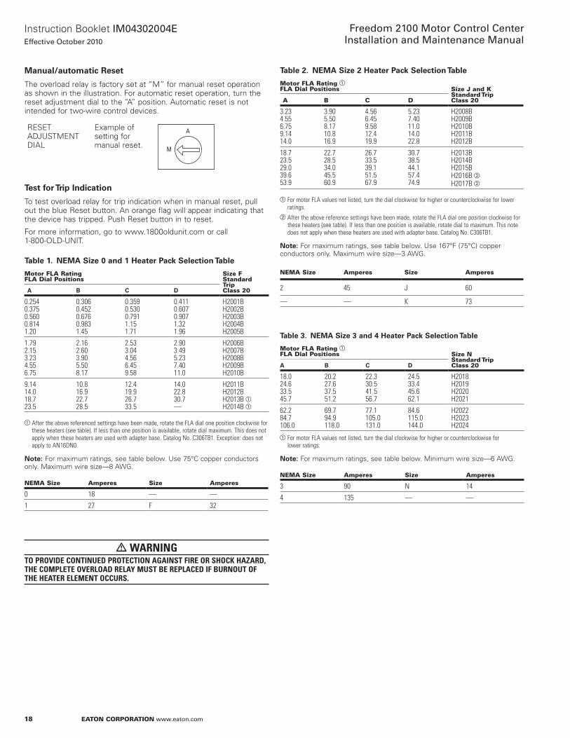
Manual/automatic Reset
Theoverloadrelayisfactorysetat“M”formanualresetoperationasshownintheillustration .Forautomaticresetoperation,turntheresetadjustmentdialtothe“A”position .Automaticresetisnotintendedfortwo-wirecontroldevices .
RESETADJUSTMENTDIAL
Exampleofsettingformanualreset .
TestforTripIndication
Totestoverloadrelayfortripindicationwheninmanualreset,pullouttheblueResetbutton .Anorangeflagwillappearindicatingthatthedevicehastripped .PushResetbuttonintoreset .
Formoreinformation,gotowww .1800oldunit .comorcall1-800-OLD-UNIT .
Table1. NEMASize0and1HeaterPackSelectionTable
Motor FLa rating FLa Dial positions
Size FStandard tripClass 20A B C D
0.254 0.375 0.560 0.814 1.20
0.306 0.452 0.676 0.983 1.45
0.359 0.530 0.7911.15 1.71
0.411 0.607 0.907 1.321.96
H2001BH2002BH2003BH2004BH2005B
1.79 2.15 3.23 4.55 6.75
2.16 2.603.90 5.50 8.17
2.53 3.04 4.56 6.45 9.58
2.90 3.49 5.23 7.4011.0
H2006BH2007BH2008BH2009BH2010B
9.14 14.0 18.723.5
10.8 16.9 22.7 28.5
12.4 19.9 26.7 33.5
14.0 22.8 30.7—
H2011BH2012BH2013B aH2014B a
aAfter the above referenced settings have been made, rotate the FLA dial one position clockwise for these heaters (see table). If less than one position is available, rotate dial maximum. This does not apply when these heaters are used with adapter base. Catalog No. C306TB1. Exception: does not apply to AN16DN0.
otee:N Formaximumratings,seetablebelow .Use75°Ccopperconductorsonly .Maximumwiresize—8AWG .
neMa Size amperes Size amperes
0 18 — —
1 27 F 32
warningto provide Continued proteCtion againSt fire or SHoCk Hazard, tHe CoMplete overload relay MuSt be replaCed if burnout of tHe Heater eleMent oCCurS.
A
M
Table2. NEMASize2HeaterPackSelectionTable
Motor FLa rating aFLa Dial positions Size J and K
Standard tripClass 20a B C D
3.23 4.55 6.75 9.14 14.0
3.90 5.50 8.17 10.8 16.9
4.56 6.45 9.58 12.4 19.9
5.23 7.40 11.0 14.0 22.8
H2008BH2009BH2010BH2011BH2012B
18.7 23.5 29.0 39.6 53.9
22.7 28.5 34.0 45.5 60.9
26.7 33.5 39.1 51.5 67.9
30.7 38.5 44.1 57.474.9
H2013BH2014BH2015BH2016B bH2017B b
aFor motor FLA values not listed, turn the dial clockwise for higher or counterclockwise for lower ratings.
bAfter the above reference settings have been made, rotate the FLA dial one position clockwise for these heaters (see table). If less than one position is available, rotate dial to maximum. This note does not apply when these heaters are used with adapter base. Catalog No. C306TB1.
otee:N Formaximumratings,seetablebelow .Use167ºF(75°C)copperconductorsonly .Maximumwiresize—3AWG .
neMa Size amperes Size amperes
2 45 J 60
— — K 73
Table3. NEMASize3and4HeaterPackSelectionTable
Motor FLa rating aFLa Dial positions Size n
Standard tripClass 20A B C D
18.0 24.6 33.5 45.7
20.2 27.6 37.5 51.2
22.3 30.5 41.5 56.7
24.5 33.4 45.6 62.1
H2018H2019H2020H2021
62.2 84.7 106.0
69.7 94.9 118.0
77.1 105.0 131.0
84.6 115.0 144.0
H2022H2023H2024
aFor motor FLA values not listed, turn the dial clockwise for higher or counterclockwise for lower ratings.
otee:N Formaximumratings,seetablebelow .Minimumwiresize—6AWG .
neMa Size amperes Size amperes
3 90 N 14
4 135 — —

19
InstructionBookletIM04302004EEffective October 2010
Freedom 2100 Motor Control CenterInstallation and Maintenance Manual
eaton Corporation www.eaton.com
Table4. NEMASize5HeaterPackSelectionTable
Motor FLa rating aFLa Dial positions
Standard tripClass 20a B C D
34 49 72
41 59 87
48 69 103
54 79 118
H2003BH2004BH2005B
107 129 194
130 156 234
152 182 274
174 209 —
H2006BH2007BH2008B
aFLA rating marked on heater pack multiplied by a transformation ratio. For motor FLA values not listed, turn the dial clockwise for higher or counterclockwise for lower ratings.
otee:N Formaximumratings,seetablebelow .Minimumwiresize—2AWG .
neMa Size amperes
5 270
Table5. NEMASize6HeaterPackSelectionTable
Motor FLa rating aFLa Dial positions
Standard tripClass 20a B C D
144 215
174 259
205 304
235 348
H2005BH2006B
258 388
312 468
365 547
419 —
H2007BH2008B
aFLA rating marked on heater pack multiplied by a transformation ratio. For motor FLA values not listed, turn the dial clockwise for higher or counterclockwise for lower ratings.
otee:N Formaximumratings,seetablebelow .
neMa Size amperes
6 540
Table6. MagneticReduced-VoltageStarterClassesF600,F700,F890withC306ThermalOverloadRelay
Starter type Class
Multiply actual Motor Full Load Current by Factor Below and refer to adjusted Full Load Current Column in tables
Quantity of Heaters required per Starter
Autotransformer F600 1 3
Part-winding F700 0.5 6
Star-delta F800 0.575 3

20
InstructionBookletIM04302004EEffective October 2010
Freedom 2100 Motor Control CenterInstallation and Maintenance Manual
eaton Corporation www.eaton.com
part 8. inspection prior to energizing
1. Beforeenergizingthemotorcontrolcenter(MCC),conductathoroughinspectiontomakecertainthatallforeignmaterials,suchastools,scrapsofwire,andotherdebris,areremovedfromallunitsandthestructure .Removeanyaccumulationofdustanddirtwithavacuumcleaner .
2. Allcircuitconnectionsaretightenedattimeofassemblybypower-driventoolswithcontrolledtorque .However,thevibrationsexperiencedintransitmayloosensomeoftheseconnections .Checkatleast10%ofthetotalconnectionsforatightconnection .Shouldthisspot-checkrevealsomelooseconnections,itwillbenecessarytocheckallconnectionpoints.Theconnectionstobecheckedincludebushardware,circuitbreakerandswitchterminals,contactorandrelayterminals,andterminalblocks .Alwayschecktheincominglineconnections .TightentothetorquevaluesshowninTable7 .
3. RemoveallblocksorothertemporaryholdingmeansusedforshipmentfromallcomponentdevicesintheMCCinterior .
4. Checktheenclosuretoseethatithasnotbeendamagedsoastoreduceelectricalspacings .
5. CompareallcircuitsforagreementwiththewiringdiagramsthataccompanytheMCC .Besurethateachmotorisconnectedtoitsintendedstarter .
6. Makecertainthatfieldwiringisclearoflivebussesandphysicallysecuredtowithstandtheeffectsoffaultcurrent .
7. Checktodeterminethatallgroundingconnectionsaremadeproperly .
8. Checkalldevicesfordamage .Makeallnecessaryrepairsorreplacements,priortoenergizing .
9. Manuallyexerciseallswitches,circuitbreakers,andotheroperatingmechanismstomakecertainthattheyareproperlyalignedandoperatefreely .
10. Testanyground-faultprotectionsystemsthatwerefurnished .
11. Setanyadjustablecurrentandvoltagetripmechanismstothepropervalues .
12. Ensurethatoverloadrelayheaterelementsareinstalledandselectedtothefull-loadcurrentshownonthenameplateofeachmotor .
13. InstallpowercircuitfusesinthefusibleswitchesinaccordancewithNECapplicationrequirements .Makesurethatfusesarecompletelyinsertedintheclipsprovided .Donotattempttodefeattherejectionfeatureonthefuseclip,whenprovided .
14. Donotoperateacurrenttransformerwithitssecondarycircuitopen .Ensurecurrenttransformerisconnectedtoaload,orasecondaryshortingbarisinstalled .
15. Topreventpossibledamagetoequipmentorinjurytopersonnel,checktoensurethatallpartsandbarriersthatmayhavebeenremovedduringwiringandinstallationhavebeenproperlyreinstalled .
16. ConductanelectricalinsulationresistancetesttomakesurethattheMCCandfieldwiringarefreefromshortcircuitsandgrounds .Dothistestphase-to-phase,phase-to-ground,andphase-to-neutral,withtheswitchesorcircuitbreakersopened .
17. IftheMCCcontainsalabyrinthverticalbusbarriersystem,verifytheoperationoftheautomaticshutters .SeePart9foradjustmentsofthismechanism .
18. Installcovers,closedoors,andmakecertainthatnowiresarepinchedandthatallenclosurepartsareproperlyalignedandtightened .
19. TurnallcircuitbreakersandfusibleswitchestotheOFFpositionbeforeenergizingthebus .
Table7. DrivingTorque
Description lb-in
Control wiring
Coil leadsRelaysPushbuttonsControl fuse blocksAuxiliary contacts
8 lb-in8 lb-in8 lb-in8 lb-in8 lb-in
Control wiring terminal blocks
Side-mounted lug/compressionRail-mounted lug typeRail-mounted compression type
9 lb-in12 lb-in18 lb-in

21
InstructionBookletIM04302004EEffective October 2010
Freedom 2100 Motor Control CenterInstallation and Maintenance Manual
eaton Corporation www.eaton.com
Table8. PowerWiringe:Starters
For Freedom Starters with C306 overload & Freedom Contactors tightening torque Conductors
Size 1 Contactor 20 lb-in Use 75°C copper conductorsSize 2 Contactor Wire size (AWG) Torque (lb-in)
14–10 35
8 40
6–4 45
3–2 50
Size 3 and Freedom Compact Size 4 (CN15MN)
Wire size (AWG) Torque (lb-in)
Slotted head screw
8 40
6–4 45
3–1/0 50
Socket head screw
Socket size (in) Torque (lb-in)
3/16 120
1/4 200
5/16 250
Size 4 275 lb-in
Size 5 500 lb-in
Starter with C440 Solid State overload
Wire size (AWG) Torque (lb-in)
NEMA 1 & 2 12-10 23
8-6 28
NEMA 3 6-1 28
Table9. FusedSwitches
Description lb-in
30A fuse assembly60A fuse assembly100A fuse assembly
25 lb-in50 lb-in50 lb-in
200A fuse assembly400A fuse assembly600A fuse assembly
300 lb-in300 lb-in300 lb-in
Breakers—Refertotorquevaluesonbreakercase .
Table10. IncomingLineLugs
Description lb-in
#2/0–350 MCM#2/0–650 MCM
360 lb-in360 lb-in
#2/0–750 MCM500–1000 MCM
500 lb-in600 lb-in
Table11. BusBolts
Description lb-in
All 276 lb-in (23 lb-ft)

22
InstructionBookletIM04302004EEffective October 2010
Freedom 2100 Motor Control Center Installation and Maintenance Manual
eaton Corporation www.eaton.com
part 9. Unit installation and adjustment DoorRemovalandInstallation
All doors on the control center are mounted on pin hinges to facilitate removal for installation and maintenance opera-tions. With the operating handle on the OFF position, rotate the quarter-turn latches, open the door, remove the hinge pins as shown in Figure 28, partially close the door and lift it from the structure. Reverse this procedure for installation.
UnitRemovalandInstallation
Afteropeningand/orremovingtheunitdoor,thecontrolunitisexposed .Withascrewdriver,pushinonthelatchatthetopcenteroftheunitandrotate¼turncounterclockwise .
CautionunitS 18” or More HigH Have a retaining braCe at tHe lower edge of eaCH Side of tHe unit fraMe to add Stability in SHipping. tHe SHipping braCeS May be retained or reMoved after inStallation; unSCrew prior to unit witHdrawal.
Pull-apartterminalblocksintheverticalwirewaymustbedisengaged(seeFigure29andpage9)andwiringfromtheunittootherunits,tomasterterminalblocksortoloaddevicesmustbedisconnectedbeforetheunitisremoved .GrasptheunitasshowninFigure30andpullitoutward .Thefirstinchoftravelpullsthestabsfreefromtheverticalbus,andthegroundingcliponthesideoftheunitframeisalsodisengaged .
Toreplaceacontrolunit,positionthemountingpointsontheunitframewiththematingguiderails .Slidetheunitinwarduntilallfourmountingpointsareengaged,thenmoveitinwardwithaquickpush .Thismovementeasilyovercomesthecompressionofthestabsastheyengagetheverticalbus .Withtheunitinitscorrectposition,thequarter-turnlatchiseasilyengagedbypushinginwardandrotating¼turnclockwise .
Figure28.HingePInRemoval
Figure29.DisengagingPull-ApartTerminalBlocks
Figure30.WithdrawingaUnit

23
InstructionBookletIM04302004EEffective October 2010
Freedom 2100 Motor Control CenterInstallation and Maintenance Manual
eaton Corporation www.eaton.com
Detent Position
Formaintenanceandtestpurposes,theunitcanbepartiallywith-drawn(approximately1½inches)untilthestabsarefreeofthebus .Inthisposition,thequarter-turnlatchcanberotatedclockwisetoengagethedetentpositionslot;thiswillsecuretheunittoensurethestabsremaindisengagedduringmaintenance .SeeFigure31 .Thelatchcanbepadlockedinthisposition .
Operating Handle Linkage Adjustment
Movementoftheoperatinghandleintheverticalplaneshouldnotberestrictedbythehandlecavityateitherthetoporbottomtoitstravel .Shouldrestrictionoccur,eliminateitadjustingthelengthoftheoperatinglinkageasshowninFigure32 .Dependingonthetypeofprimarydisconnectdevicecontainedinthecontrolunit,itmaybenecessarytolengthenorshortenthelinkage .
Automatic Shutter Travel Adjustment
Whentheoptionallabyrinthverticalbusbarrierisinstalledinthecontrolcenter,ashutterisprovidedtoautomaticallycoverthestabopeningswhenacontrolunitiswithdrawn .Theshutterisopenedbyengagementoftheleft-handsideofthecontrolunitwiththeshutterarmlinkageattachedtotheleft-handverticalstructuralmembers .Whentheunitiswithdrawnfreeofthelinkage,aspringautomati-callymovestheshuttertoitsclosedposition .SeeFigure33andFigure4 .
Withthecontrolunitremoved,theshuttershouldcompletelycomerthestabopenings .Ifitdoesnotcovertheopenings,useanadjust-ablewrenchtobendthelinkarmtotherightuntiltheshuttercoversthestabopenings .
If,onre-insertionofthecontrolunit,interferenceisfeltbetweenthestabassemblyattherearoftheunitandtheshutter,theengage-mentofthecontrolunitwiththeshutterarmlinkageisinsufficienttofullyopentheshutter .Useanadjustablewrenchtobendthelink-agearminwardtowardtheunittoincreaseitsengagementwiththeunit .Aninwardbendofapproximately¼inchwillprovidesufficientadditionalshuttertravel
InstallingPilotDevices
The device panel can accommodate up to six pilot devices such asoil-tightpushbuttons,indicatinglights,selectorswitchesandminia-turemeters .Ifunusedspaceisavailableandtheadditionofotherdevicesisdesired,observethefollowingprocedure .
Afteropeningtheunitdoor,loosenthetwoscrewsatthetopofthedevicepanel .Slidethepanel½inchlefttopermitittoswingdownforaccess .SeeFigure34 .Withthepeenendofaball-peenhammerorwithadriftorchisel,removethedesiredknockout .
Figure31.UnitLockedinDetentPosition
Figure32.OperatingHandleLinkageAdjustment
Figure33.ShutterArmLinkage

24
InstructionBookletIM04302004EEffective October 2010
Freedom 2100 Motor Control CenterInstallation and Maintenance Manual
eaton Corporation www.eaton.com
CautionbraCe tHe panel Solidly to avoid breaking tHe Hinge pintS. uSe a knife or SMall file to reMove reMaining plaStid burrS. inStall and wire tHe new deviCe and re-attaCH teH top of tHe deviCe panel to tHe unit.
Figure34.UnitDevicePanel
InstallingaNewUnit
Itisrecommendedthatanewunitbeinstalledinaunitspaceatthetopofaverticalcompartmentordirectlybelowanexistingunit .Materialprovidedwiththenewunitbythefactoryincludes:Adivid-erpanwithintegralguiderails,aunitdoor,hinges,catchesandhard-ware .Observethefollowingsequenceofoperationsforinstallation .
1 . Removetheexistingblankdoor .
2 . Positionthenewunitdoorovertheopenspacetoensurethehingesandlatchesarealigned .Ifthespacesdiffer,thehingesandlatchesonthestructuremustbere-locatedtomatchtheunitdoorhingesandlatches .Mountthedoor,usingthehingepinsprovided .
3 . Installthenewdividerpaninthenotchesprovidedintherearbarriersothatitisalignedwiththebottomofthenewdoor .Attachthepantotheverticalstructurechannelswithonethread-formingscrewoneachside .
4 . Removefromtheverticalbusbarriertheflatplatewhichcoversthestabholesthatwillalignwiththestabsonthenewunit .Ifanoptionallabyrinthverticalbusbarrierisinplace,installanauto-maticshutteroverthestabcutouts .Followtheinstructionsheetprovidedwiththeshutterkit .
part 10. MaintenancePreventiveMaintenance
Preventivemaintenanceshouldbeaprogram,ascheduledperiodicactionthatbeginswiththeinstallationoftheequipment .Atthattime,specificmanufacturer’sinstructionliteratureshouldbeconsulted,thenstoredforfuturereference .Follow-upmaintenanceshouldbeatregularintervals,asfrequentlyastheseverityofdutyjustifies .Timeintervalsofoneweek,oronemonth,oroneyearmaybeappropriate,dependingontheduty .Itisalsodesirabletoestablishspecificchecklistsforeachcontrol,aswellasalogbooktorecordthehistoryofincidents .Asupplyofrenewalpartsshouldbeobtainedandstored .
Thiscontrolequipmentisdesignedtobeinstalled,operated,andmaintainedbyadequatelytrainedworkmen .Theseinstructionsdonotcoveralldetails,variations,orcombinationsoftheequipment,itsstorage,delivery,installation,check-out,safeoperation,ormaintenance .Caremustbeexercisedtocomplywithlocal,state,andnationalregulations,aswellassafetypractices,forthisclassofequipment .
Authorizedpersonnelmayopenaunitdoorofamotorcontrolcenter(MCC)whilethestarterunitisenergized .Thisisaccomplishedbydefeatingthemechanicalinterlockbetweentheoperatingmechanismandtheunitdoor .Aclockwisequarterturnoftheslottedheadscrewlocatedabovetheoperatinghandlewillallowthedoortoopen .SeeFigure355 .
Whenservicingandadjustingtheelectricalequipment,refertotheapplicabledrawingscoveringthespecificmotorcontrolcenterMCCandanyotherrelatedinterconnectiondrawings .Followanyinstruc-tionsthatmaybegivenforeachdevice .Alistofinstructionleafletscoveringstandardcomponentsisshownonpage31ofthismanual .AnyoftheseleafletsmaybeobtainedbycontactingyournearestEatonrepresentative .
GeneralGuidelines—Thewholepurposeofmaintainingelectricalequipmentcanbesummarizedintworules:
1. Keepthoseportionsconductingthatareintendedtobeconducting .
2. Keepthoseportionsinsulatedthatareintendedtobeinsulated .
Goodconductionrequiresclean,tightjoints,freeofcontaminantssuchasdirtandoxides .
Goodinsulationrequirestheabsenceofcarbontrackingandtheabsenceofcontaminants,suchassaltanddustthatbecomehydroscopicandprovideanunintendedcircuitbetweenpointsofoppositepolarity .
Figure35.DefeaterMechanism

25
InstructionBookletIM04302004EEffective October 2010
Freedom 2100 Motor Control CenterInstallation and Maintenance Manual
eaton Corporation www.eaton.com
CautionMaintenanCe of tHe Control CoMponentS requireS tHat all power to tHeSe CoMponentS be turned off by opening tHe branCH CirCuit diSConneCt MeanS and witHdrawing tHe unit to tHe detent poSition (See figure 31) or reMoving tHe unit entirely froM tHe MCC. wHen unitS are fully inSerted into tHe MCC, tHe line Side of eaCH diSConneCt iS energized. do not work on fixed unitS unleSS tHe Main diSConneCt for tHe MCC iS off..
WhenworkingonportionsofabranchcircuitremotefromtheMCC,lockthedisconnectmeansforthatcircuitintheOFFposition .TopositivelylocktheoperatingmechanismintheOFFposition,ametallockingbarrecessedinthehandlemaybeextendedandpadlockedwithfromonetothreepadlocks .SeeFigure36 .
Figure36.LockingOutaDisconnect
WiththedooropenandthedisconnectdeviceOFF,theoperatinghandleismechanicallyinterlockedtopreventinadvertentlybeingpushedON .Todefeatthisinterlock,thebaronthetopofthemecha-nismshouldbepushedinslightly,allowingthehandletomoveupwardtotheONposition .
warningif fully inSerted, tHe power and Control CirCuitS will be energized. padloCking to prevent tHiS Handle MoveMent May be aCCoMpliSHed by tHe SaMe MetHod aS deSCribed above.
Separatecontrolsourcesofpowermustalsobedisconnected .Ifcontrolpowerisusedduringmaintenance,takestepstopreventfeedbackofahazardousvoltagethroughacontroltransformer .Bealerttopowerfactorcorrectioncapacitorsthatmaybecharged .Dischargethembeforeworkingonanypartoftheassociatedpowercircuit .
Cleaning.Soot,smoke,orstainedareas(otherthaninsidearcchutes),orotherunusualdeposits,shouldbeinvestigatedandthesourcedeterminedbeforecleaningisundertaken .Vacuumorwipecleanallexposedsurfacesofthecontrolcomponentandtheinsideofitsenclosure .Equipmentmaybeblowncleanwithcompressedairthatisdryandfreefromoil .(Bealerttobuilt-inoilersinfactorycompressedairlines!)Ifairblowingtechniquesareused,removearccoversfromcontactorsandsealopeningstocontrolcircuitcontacts
thatarepresent .Itisessentialthattheforeigndebrisberemovedfromthecontrolcenter,notmerelyrearranged .Controlequipmentshouldbecleananddry .Removedustanddirtinsideandoutsidethecabinetwithoutusingliquidcleaner .Removeforeignmaterialfromtheoutsidetopandinsidebottomoftheenclosure,includ-inghardwareanddebris,sothatfutureexaminationwillrevealanypartsthathavefallenoffordroppedontotheequipment .Ifthereareliquidsspreadinside,determinethesourceandcorrectbysealingconduit,addingspaceheaters,orotheractionasapplicable .
MechanicalChecks.Tightenallelectricalconnections .Lookforsignsofoverheatedjoints,charredinsulation,discoloredterminals,andthelike .Mechanicallycleantoabrightfinish(don’tuseemerypaper)orreplacethoseterminationsthathavebecomediscolored .Determinethecauseoftheloosejointandcorrect .Beparticularlycarefulwithaluminumwireconnections .Aluminumwireisbestterminatedwithacrimptypelugthatisattachedtothecontrolcomponent .Whenscrewtypelugs(markedCU/AL)areusedwithaluminumwire,thejointshouldbecheckedfortightnessevery200operationsofthedevice .
Wiresandcablesshouldbeexaminedtoeliminateanychafingagainstmetaledgescausedbyvibration,thatcouldprogresstoaninsulationfailure .Anytemporarywiringshouldberemovedorpermanentlysecuredanddiagramsmarkedaccordingly .
Theintendedmovementofmechanicalparts,suchasthearmatureandcontactsofelectromechanicalcontactors,andmechan-icalinterlocksshouldbecheckedforfreedomofmotionandfunctionaloperation .
Wrap-up.Checkallindicatinglamps,mechanicalflags,doors,latches,andsimilarauxiliariesandrepair,ifrequired .
Logchangesandobservationsintorecordbookbeforereturningequipmentintoservice .Donotremoveanylabelsornameplates .Restoreanythataredamaged .
ContactWearandReplacement
Contactorsaresubjecttobothmechanicalandelectricalwearduringtheiroperation .Inmostcases,mechanicalwearisinsignificant .Theerosionofthecontactsisduetoelectricalwear .Duringarcing,materialfromeachcontactis vaporizedandblownawayfromtheusefulcontactingsurface .
Acriticalexaminationoftheappearanceofthecontactsurfacesandameasurementoftheremainingcontactover-travelwillgivetheusertheinformationrequiredtogetthemaximumcontactlife .
Over-travelMeasurement
Contactlifehasendedwhentheover-travelofthecontactshasbeenreducedto0 .02inch .
Over-travelofthecontactassemblyisthatpartofthestrokethatthemovingcontactswouldtravelaftertouchingthefixedcontactsiftheywerenotblockedfrommovementbythefixedcontacts .
Amethodofmeasuringover-travelisasfollows:
A. Placea0 .02-inchfeelergaugebetweenthearmatureandmagnet,withthearmatureheldtightlyagainstthemagnet .
B. Checkcontinuallyineachphase,i .e .,determineifcircuitfromterminal-to-terminalforeachpoleisopenundertheseconditions .
C. Ifthereiscontinuitythroughallphases,theremainingover-travelissufficient .Ifthereisnotcontinuitythroughallphases,replaceallstationaryandmovingcontactsplusmovingcontactover-travelsprings .Afterreplacingparts,manuallyoperatecontactortobesurebindingdoesnotoccur .

26
InstructionBookletIM04302004EEffective October 2010
Freedom 2100 Motor Control CenterInstallation and Maintenance Manual
eaton Corporation www.eaton.com
Table12. ContactorTroubleshootingChart
Defect Cause remedy
Short contact life Low contact force Adjust over-travel, replace contacts, and replace contact springs as required to correct contact force.
Contact bounce on opening or closing
Correct improper voltage applied to coil. Correct any mechanical defects or misalignment.
Abrasive dust on contacts
Do not use emery cloth to dress contacts.
Load current is too high
Reduce load. Use larger contactor.
Jogging cycle is too severe
Reduce jogging cycle. Check factory for more durable contact material. Use larger contactor.
Overheating Load current too high Install arc box.
Loose connections Replace broken or eroded insulating parts, arc horns, and grid plates. Clean or replace insulating parts having a heavy coating of foreign conducting material.
Over-travel and/or contact force too low
Remove contaminating materials that may have accumulated on arc horns and steel-grid plates.
Ambient temperature is too high
Reduce load. Provide better ventilation. Relocate starter. Use larger contactor.
Line and/or load cables are too small
Install terminal block and run larger conductors between contactor and terminal block.
Welding of contacts Over-travel and/or contact force is too low
Adjust over-travel, replace contacts, and replace contact springs as required to correct contact force.
Magnet armature stalls or hesitates at contact touch point
Correct low voltage at coil terminals as coil draws inrush current.
Contactor drops open to contact-touch position because of voltage dip
Maintain voltage at coil terminals. Install low voltage protective device, sometimes called “Brownout Protector.”
Excessive contact bounce on closing
Correct coil overvoltage condition.
MaintenanceofMotorControllersafteraFault
otee:N ReproducedbypermissionoftheNationalElectricalManufacturersAssociationfromNEMAStandardsPublicationNo .ICS2-2000(R2005),IndustrialControlDevices,ControllersandAssemblies,copyright2000byNEMA .
Inamotorbranchcircuitthathasbeenproperlyinstalled,coordinated,andinservicepriortothefault,openingofthebranch-circuitshort-circuitprotectivedevice(fuse,circuitbreaker,motorshort-circuitprotector,andsoon)indicatesafaultconditioninexcessofoperatingoverload .Thisfaultconditionmustbecorrectedandthenecessaryrepairorreplacementsmadebeforere-energizingthebranchcircuit .
Itisrecommendedthatthefollowinggeneralproceduresbeobservedbyqualifiedpersonnelintheinspectionandrepairofthemotorcontrollerinvolvedinthefault .
Procedure
Cautionall inSpeCtionS and teStS are to be Made on ControllerS and equipMent tHat are de-energized, diSConneCted, and iSolated So tHat aCCidental ContaCt Cannot be Made witH live partS and So tHat all plant Safety proCedureS will be obServed.
Enclosure.Substantialdamagetotheunitdoororframe,suchasdeformation,displacementofparts,orburning,requiresreplacementoftheentireunit .
CircuitBreaker.Examinetheunitinteriorandthecircuitbreakerforevidenceofpossibledamage .Ifevidenceofdamageisnotapparent,thebreakermayberesetandturnedON .Ifitissuspectedthatthecircuitbreakerhasopenedseveralshort-circuitfaultsorifsignsofcircuitbreakerdeteriorationappearwithintheenclosure,thecircuitbreakershouldbereplaced .
DisconnectSwitch.Theexternaloperatinghandleofthedisconnectswitchmustbecapableofopeningtheswitch .Ifthehandlefailstoopentheswitchorifvisualinspectionafteropeningindicatesdeteriorationbeyondnormalwearandtear,suchasoverheating,con-tactblade,orjawpitting,insulationbreakageorcharring,theswitchmustbereplaced .
FuseHolders.Deteriorationoffuseholdersortheirinsulatingmountsrequirestheirreplacement .
TerminalsandInternalConductors.Indicationsofarcingdamageand/oroverheating,suchasdiscolorationandmeltingofinsulation,requirethereplacementofdamagedparts .
Contactor.Contactsshowingheatdamage,displacementofmetal,orlossofadequatewearallowancerequirereplacementofthecontactsandthecontactsprings .Ifdeteriorationextendsbeyondthecontacts,suchasbindingintheguidesorevidenceofinsula-tiondamage,thedamagedpartsortheentirecontactormustbereplaced .
OverloadRelays.Ifburnoutofthecurrentelementofanoverloadrelayhasoccurred,thecompleteoverloadrelaymustbereplaced .Anyindicationthatanarchasstruckand/oranyindicationofburningoftheinsulationoftheoverloadrelayalsorequiresreplacementoftheoverloadrelay .
Ifthereisnovisualindicationofdamagethatwouldrequirereplacementoftheoverloadrelay,therelaymustbeelectricallyormechanicallytrippedtoverifytheproperfunctioningoftheoverloadrelaycontact(s) .
ReturntoService.Beforereturningthecontrollertoservice,checksmustbemadeforthetightnessofelectricalconnectionsandfortheabsenceofshortcircuits,grounds,andleakage .
Allequipmentenclosuresmustbeclosedandsecuredbeforethebranchcircuitisenergized .

27
InstructionBookletIM04302004EEffective October 2010
Freedom 2100 Motor Control CenterInstallation and Maintenance Manual
eaton Corporation www.eaton.com
Figure37.NormalServiceWear
Contact Tip
Contact Plate(Brass or Copper)
NewStillServiceable
Figure38.EndofServiceLife
Corner of ContactWorn Away
Replace
Figure39.NEMA3RMCC-AllFiltersRequireCleaningonRegularBasis
CLEAN FILTER ON A REGULAR BASIS.
ACCESS FILTER FROM THE OUTSIDE OF THE ENCLOSURE.
CLEAN FILTER ON A REGULAR BASIS.
ACCESS FILTER FROM THE OUTSIDE OF THE ENCLOSURE.
28
InstructionBookletIM04302004EEffective October 2010
Freedom 2100 Motor Control CenterInstallation and Maintenance Manual
eaton Corporation www.eaton.com
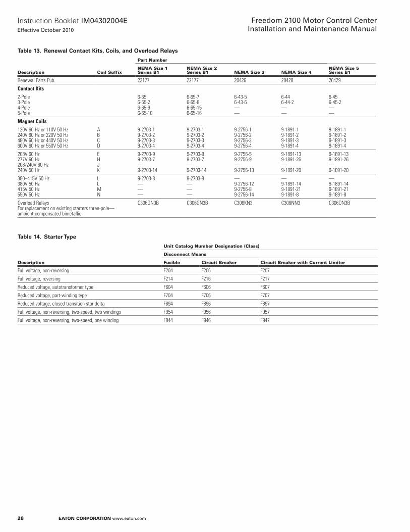
Table13. RenewalContactKits,Coils,andOverloadRelays
Description Coil Suffix
part number
neMa Size 1Series B1
neMa Size 2Series B1 neMa Size 3 neMa Size 4
neMa Size 5Series B1
Renewal Parts Pub. 22177 22177 20426 20428 20429
Contact kits
2-Pole3-Pole4-Pole5-Pole
6-656-65-26-65-96-65-10
6-65-76-65-86-65-156-65-16
6-43-56-43-6——
6-446-44-2——
6-456-45-2——
Magnet Coils
120V 60 Hz or 110V 50 Hz240V 60 Hz or 220V 50 Hz480V 60 Hz or 440V 50 Hz600V 60 Hz or 550V 50 Hz
ABCD
9-2703-19-2703-29-2703-39-2703-4
9-2703-19-2703-29-2703-39-2703-4
9-2756-19-2756-29-2756-39-2756-4
9-1891-19-1891-29-1891-39-1891-4
9-1891-19-1891-29-1891-39-1891-4
208V 60 Hz277V 60 Hz208/240V 60 Hz240V 50 Hz
EHJK
9-2703-99-2703-7—9-2703-14
9-2703-99-2703-7—9-2703-14
9-2756-59-2756-9—9-2756-13
9-1891-139-1891-26—9-1891-20
9-1891-139-1891-26—9-1891-20
380–415V 50 Hz380V 50 Hz415V 50 Hz550V 50 Hz
LLMN
9-2703-8———
9-2703-8———
—9-2756-129-2756-89-2756-14
—9-1891-149-1891-219-1891-8
—9-1891-149-1891-219-1891-8
Overload Relays For replacement on existing starters three-pole— ambient-compensated bimetallic
C306GN3B C306GN3B C306KN3 C306NN3 C306DN3B
Table14. StarterType
Description
Unit Catalog number Designation (Class)
Disconnect Means
Fusible Circuit Breaker Circuit Breaker with Current Limiter
Full voltage, non-reversing F204 F206 F207
Full voltage, reversing F214 F216 F217
Reduced voltage, autotransformer type F604 F606 F607
Reduced voltage, part-winding type F704 F706 F707
Reduced voltage, closed transition star-delta F894 F896 F897
Full voltage, non-reversing, two-speed, two windings F954 F956 F957
Full voltage, non-reversing, two-speed, one winding F944 F946 F947

29
InstructionBookletIM04302004EEffective October 2010
Freedom 2100 Motor Control CenterInstallation and Maintenance Manual
eaton Corporation www.eaton.com
part 11. plan Views
Figure40.20InchesWide,16InchesDeep,FrontMountedOnly(4710A30)
Figure41.24InchesWide,16InchesDeep,FrontMountedOnly(4710A33)
5.41(137.4)
2.20 (55.9)
1.25 (31.7)
Top Conduit Space
17.50(444.5)20.00
(508.0)
Top View
Vertical Wireway Door
16.00(406.4)
1.25 (31.7)
Cross Section
4.81 (122.2)
7.31(185.7)
Wire TieBrackets
VerticalWirewayBottom View
17.50(444.5)
6.81 (172.9)
5.41 (137.4)
See Note 5
1.58 (40.1)16.00
(406.4)
Removable BottomFrame MembersSee Note 413.97
(354.8)
Removable Top Cover
0.70 (17.8)
1.25 (31.7)1.25 (31.7)
Bottom Conduit SpaceSee Notes 2 and 3
0.53 (13.5) Dia. See Notes 1 and 1A0.53 (13.5) Dia.See Notes 1 and 1B
Cross Section
5.41(137.4)
2.20 (55.9)
Top Conduit Space
1.25 (31.7)21.50
(546.1)24.00 (609.6)
1.25 (31.7)
Top View
Vertical Wireway Door
16.00(406.4)
Removable Top Cover
8.81 (233.7)
7.31(185.7)
Vertical Wireway
Wire TieBrackets
1.25(31.7)
1.25(31.7)
21.50(546.1)
0.53 (13.5) Dia.See Notes 1 and 1B
5.41 (137.4)
See Note 5
6.81 (172.9)
1.58 (40.1)
Bottom Conduit SpaceSee Notes 2 and 3
Removable BottomFrame MembersSee Note 5
Bottom View
0.70 (17.8)20.00
(508.0)0.53 (13.5) Dia. See Notes 1 and 1A
2.00 (50.8)
13.97(354.8)
Figure42.20InchesWide,21InchesDeep,FrontMountedOnly(4710A31)
Figure43.24InchesWide,21InchesDeep,FrontMountedOnly(4710A34)
5.41(137.4)
2.20 (55.9)1.25 (31.7)
Top Conduit Space
17.50(444.5)20.00
(508.0)
Top View
Vertical Wireway Door
20.38(517.7)
1.25 (31.7)
Cross Section
4.81 (122.2)
7.31(185.7)
Wire TieBrackets
VerticalWireway
Bottom View17.50
(444.5)
5.78 (146.8)
5.41 (137.4)
5.41 (137.4)
See Note 5
1.58 (40.1)16.00
(406.4)
Removable BottomFrame MembersSee Note 4
18.35(466.1
Removable Top Cover
0.70 (17.8)
1.25(31.7)
1.25(31.7)
Bottom Conduit SpaceSee Notes 2 and 3
0.53 (13.5) Dia. See Notes 1 and 1A
2.00 (50.8)0.53 (13.5) Dia.See Notes 1 and 1B
Removable BottomFrame MembersSee Note 518.35
(466.1)
0.70 (17.8)
Bottom Conduit SpaceSee Notes 2 and 3
5.78 (146.8)
5.41 (137.4)
5.41 (137.4)See Note 5
1.58 (40.1)
Bottom View21.50
(546.1) 1.25 (31.7)1.25 (31.7)
20.00(508.0)
0.53 (13.5) Dia. See Notes 1 and 1A0.53 (13.5) Dia.See Notes 1 and 1B
2.00 (50.8)
5.41(137.4)
2.20 (55.9)
1.25 (31.7)
Top Conduit Space
21.50(546.1)24.00
(609.6)
Top View
Vertical Wireway Door
20.38(517.7)
1.25 (31.7)
Removable Top Cover
Cross Section7.31
(185.7)
Wire TieBrackets
VerticalWireway
8.81 (223.8)
otese:N 1 . Minimumlengthofanchorboltis2 .00(50 .8)(0 .38-16grade5torqued at31lb-ft) . A . Fornon-seismic,mountwithtwocenterboltsperenclosure . B . Forseismic,mountwithminimumfourcornerboltsperenclosure .2 .Recommendedmaximumconduitheightabovefloorlineis3 .50inches (88 .9mm) .3 .Maximumconduitspacewithchannelsillsis17 .50x9 .73inches (444 .5x247 .1mm) .4 .Formultiplestructureassemblies,eitheroneorbothofthesemembers isremovedtoprovidemaximumunrestrictedconduitspaceatthe bottomoftheMCC .5 .Thisconduitspaceisnotrecommendedwhenaneutralbusand/oraspace heaterisrequired .Otherwisethisspaceisavailableforconduit .SeeFigure4646forverticaldimensions .

30
InstructionBookletIM04302004EEffective October 2010
Freedom 2100 Motor Control CenterInstallation and Maintenance Manual
eaton Corporation www.eaton.com
Figure44.20InchesWide,21InchesDeep,FrontandRearMounted(4710A32)
Figure45.10InchesWide,16or21InchesDeep,TransitionStructure(4710A35/6)
otese:N 1 . Minimumlengthofanchorboltis2 .00(50 .8)(0 .38-16grade5torqued at31lb-ft) . A . Fornon-seismic,mountwithtwocenterboltsperenclosure . B . Forseismic,mountwithminimumfourcornerboltsperenclosure .2 .Recommendedmaximumconduitheightabovefloorlineis3 .50inches (88 .9mm) .3 .Maximumconduitspacewithchannelsillsis17 .50x9 .73inches (444 .5x247 .1mm) .4 .Formultiplestructureassemblies,eitheroneorbothofthesemembers isremovedtoprovidemaximumunrestrictedconduitspaceatthe bottomoftheMCC .
2.20 (55.9)
3.22 (81.8)
5.41 (137.4)
2.20 (55.9)1.25 (31.7)
Top Conduit Space 21.00
(533.4)
Removable Top Cover
Top View
Vertical Wireway Door
1.25 (31.7)17.50(444.5)20.00
(508.0)
Cross Section Rear Vertical Wireway
Vertical Wireway
Wire TieBrackets
7.31 (185.7)
7.31 (185.7)
17.50(444.5)
5.78 (146.8)
0.53 (13.5) Dia.See Notes 1 and 1B
5.41 (137.4)
See Note 5
5.41 (137.4)
16.00(406.4)
2.00(50.8)
Bottom Conduit SpaceSee Notes 2 and 3
Removable BottomFrame MembersSee Note 5
Bottom View
1.32 (33.5)
18.35(466.1)
0.53 (13.5) Dia. See Notes 1 and 1A
4.81 (122.2)
4.81 (122.2)
1.25 (31.7) 1.25 (31.7)
5.41(137.4)
2.20(55.9)
1.25(31.7)
10.00(254.0) 7.50
(190.5)
20.38(517.6)
or16.00
(406.4)
RemovableCover
Top ConduitSpace
1.25(31.7)
Top View
Floor Line
Neutral Bus Location When Specified
Ground BusLocation
Horizontal BusLocation
12.12 (307.8)
3.12 (79.2)4.62 (117.3)4.62 (117.3)
Removable BusBarrier
Flat CoverSupplied onRear of FrontMounted OnlyStructure
HorizontalWireway7.16 (181.9)Deep
2.25(57.2)
Vertical View
5.00(127.0)
3.00 (76.2)ChannelSills SuppliedOnly WhenSpecified
3.0(76.2)
10.50(266.7)
1.00 (25.4)
Bottom View
1.25(31.7)
7.50(190.5)
1.25(31.7)
5.41 (137.4)
5.78 (146.8)
5.41 (137.4)
See Note 5
0.53 (13.5)Dia. (2)See Note 1
Bottom Conduit Space See Notes 2 and 3
1.58 (40.1) 0.70 (17.8)
5.00 (127.0)
18.35 (466.1)
9.73 (247.1)
or 14.11 (358.4)
15.73 (399.5) or20.11 (510.8)
Removable Bottom Frame Members See Note 4. (Not to be removed for seismic)
Figure46.SideViewA
Figure47.SideViewB
5 .Thisconduitspaceisnotrecommendedwhenaneutralbusand/oraspace heaterisrequired .Otherwise,thisspaceisavailableforconduit .SeeFigure4747forverticaldimensions .7 . MasterTerminalBlock(MTB)assemblyisfurnishedforTypeCwiring onlywhenlocationnotspecified .MTBsuppliedatthebottom .8 .Rearhorizontalbusbarriernotsuppliedwithfrontmountedonlystructure .9 .Standardstructurearrangement: A . Infront WithoutMTB:AandB=9 .00(228 .6mm) WithMTBatbottom:AandB=9 .00(228 .6mm) WithMTBattop:AandB=3 .00(76 .2mm) B . Inrear WithoutMTB:C=0,D=72(1828 .8mm),E=3 .00(76 .2mm) WithMTBatbottom:C=0,D=66 .00(1676 .4mm), E=9 .00(228 .6mm)" WithMTBattop:C=12,D=60(1524 .0mm),E=3 .00(76 .2mm)
10.50(266.7)
12.12(307.8) Horizontal Bus Location
Vertical Bus Location
3.12 (79.2)
4.62 (117.3)
4.62 (117.3)
Removable Bus BarrierSee Note 8
Flat Cover Supplied on Rear of FrontMounted Only Structure
Minimum Rated VerticalBus Supplied as Standard in Front Mounted Only Structure
Ground Bus Location
2.25(57.2)
A
See Note 9A
Horizontal Wireway7.16 (181.9) Deep
See Note 7
See Note 7
See Note 9A
BFloor Line
1.00(25.4)
3.00 (76.2) ChannelSills Supplied Only When Specified
5.00(127.0)
3.00 (76.2)
9.73 (247.1) or 14.11 (358.4)
15.73 (399.5) or 20.11 (510.8)10.50
(266.7) Neutral Bus Location When Specified
10.50(266.7)
12.12(307.8)
Horizontal Bus Location See Note 9
Vertical Bus Location
3.12 (79.2)
4.62 (117.3)
4.62 (117.3)
Ground Bus Location
2.25(57.2)
A
See Note 9A
Horizontal Wireway7.16 (181.9) Deep
See Note 7
See Note 7
See Note 9A
BFloor Line
1.00(25.4)
3.00 (76.2) ChannelSills Supplied Only When Specified
5.00(127.0)
3.00 (76.2)14.11(358.4)20.11
(510.8)
10.50(266.7)
Neutral Bus Location When Specified
Removable Bus Barrier
15.00(381.0)
Rear Horizontal Wireway4.97 (126.3) Deep
See Note 7
C
D
See Note 7
E

31
InstructionBookletIM04302004EEffective October 2010
Freedom 2100 Motor Control CenterInstallation and Maintenance Manual
eaton Corporation www.eaton.com
part 12. related instructional Leaflets
publication publication no.
Starters
Size 5, Non-Reversing and Reversing, vacuum IL17087
Contactors
Size 5, Non-Reversing and Reversing, vacuum IL16999
Size 5, Non-Reversing and Reversing, vacuum IL17088
Circuit breakers
Magnum DS I.B. 2C12060H08
RotoTract Remote Racking Operating Manual IL04300001E
Series C, F-Frame IL01219018E
Series C, F-Frame IL29C101
Series C, J-Frame IL01204004E
Series C, J-Frame IL29C103
Series C, K-Frame IL29C104C
Series C, L-Frame IL01207002E
Series C, L-Frame IL29C105
Series C, N-Frame IL01209003E
Series C, N-Frame IL29C106
Series C, R-Frame IL29C613B
Series C, R-Frame IL29C107
Series G, EG-Frame IL29C515C
Series G, JG-Frame IL01207009E
Series G, LG-Frame IL01207001E
Transfer Switches IL14477

EatonCorporationElectricalSector1111SuperiorAve .Cleveland,OH44114UnitedStates877-ETN-CARE(877-386-2273)Eaton .com
©2010EatonCorporationAllRightsReservedPrintedinUSAPublicationNo .IM04302004E/TBG000341October2010
PowerChainManagementisaregisteredtrademarkofEatonCorporation .
Allothertrademarksarepropertyoftheirrespectiveowners .
InstructionBookletIM04302004EEffective October 2010
Freedom 2100 Motor Control CenterInstallation and Maintenance Manual