EFFECTIVE LOCATION OF THYRISTOR CONTROLLED...
26
i EFFECTIVE LOCATION OF THYRISTOR CONTROLLED SERIES CAPACITOR BY SENSITIVITY BASED METHOD FOR CONGESTION MANAGEMENT NOORSAKINAH BINTI ABU BAKAR A project report submitted in partial fulfilment of the requirements for the award of the degree of Master of Engineering (Electrical - Power) Faculty of Electrical Engineering Universiti Teknologi Malaysia JANUARY 2015
Transcript of EFFECTIVE LOCATION OF THYRISTOR CONTROLLED...

i
EFFECTIVE LOCATION OF THYRISTOR CONTROLLED SERIES
CAPACITOR BY SENSITIVITY BASED METHOD FOR CONGESTION
MANAGEMENT
NOORSAKINAH BINTI ABU BAKAR
A project report submitted in partial fulfilment of the
requirements for the award of the degree of
Master of Engineering (Electrical - Power)
Faculty of Electrical Engineering
Universiti Teknologi Malaysia
JANUARY 2015

iii
ACKNOWLEDGEMENT
In performing this project, I had to take the help and guideline of some
respected persons, who deserve my greatest gratitude. The completion of this project
gives me very much pleasure and first and foremost, I would like to express my
utmost gratitude to my project supervisor, Prof Ir Dr Mohd Wazir Bin Mustafa for
giving me a good guideline for this project throughout numerous consultations.
Without his continued support and advice, this project report would not have been
the same as presented here.
And not forgotten to my dearest classmates in which have made valuable
assistance and suggestion which had gave me an inspiration to improve this project
to much better. Their views and tips are useful indeed. Last but not list, I would also
like to expand my deepest gratitude to my family members and all those who have
directly and indirectly guided me in writing this project report.
iv
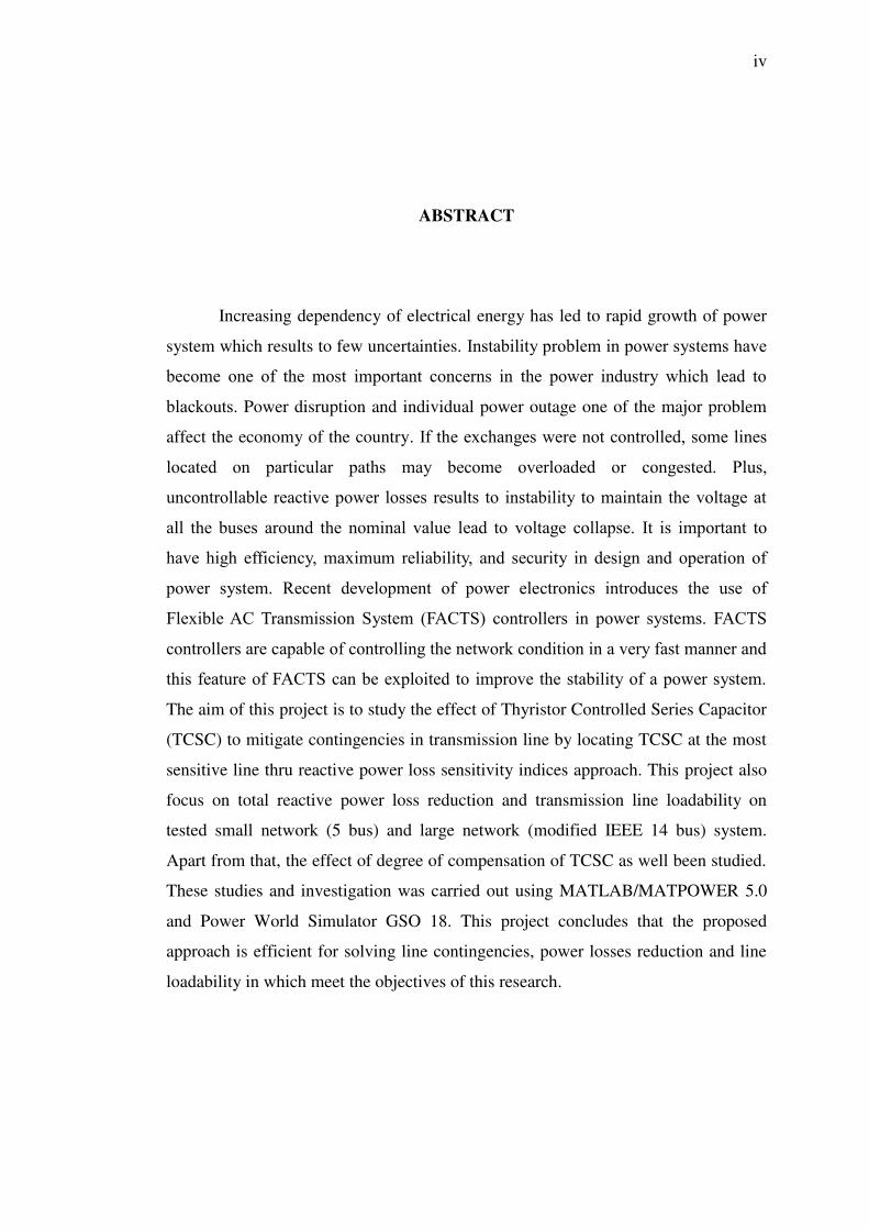
ABSTRACT
Increasing dependency of electrical energy has led to rapid growth of power
system which results to few uncertainties. Instability problem in power systems have
become one of the most important concerns in the power industry which lead to
blackouts. Power disruption and individual power outage one of the major problem
affect the economy of the country. If the exchanges were not controlled, some lines
located on particular paths may become overloaded or congested. Plus,
uncontrollable reactive power losses results to instability to maintain the voltage at
all the buses around the nominal value lead to voltage collapse. It is important to
have high efficiency, maximum reliability, and security in design and operation of
power system. Recent development of power electronics introduces the use of
Flexible AC Transmission System (FACTS) controllers in power systems. FACTS
controllers are capable of controlling the network condition in a very fast manner and
this feature of FACTS can be exploited to improve the stability of a power system.
The aim of this project is to study the effect of Thyristor Controlled Series Capacitor
(TCSC) to mitigate contingencies in transmission line by locating TCSC at the most
sensitive line thru reactive power loss sensitivity indices approach. This project also
focus on total reactive power loss reduction and transmission line loadability on
tested small network (5 bus) and large network (modified IEEE 14 bus) system.
Apart from that, the effect of degree of compensation of TCSC as well been studied.
These studies and investigation was carried out using MATLAB/MATPOWER 5.0
and Power World Simulator GSO 18. This project concludes that the proposed
approach is efficient for solving line contingencies, power losses reduction and line
loadability in which meet the objectives of this research.

v
ABSTRAK
Peningkatan kebergantungan tenaga elektrik telah membawa kepada
pertumbuhan pesat sistem kuasa yang mengakibatkan kepada beberapa
ketidaktentuan. Masalah ketidakstabilan dalam sistem kuasa telah menjadi salah satu
kebimbangan yang paling merisaukan dalam industri tenaga yang membawa kepada
kelumpuhan. Gangguan kuasa dan gangguan kuasa individu salah satu masalah
utama menjejaskan ekonomi negara. Jika bursa tidak terkawal, beberapa baris di
laluan tertentu boleh menjadi terlebih beban atau kesesakan. Tidak terkawal
kehilangan kuasa reaktif yang tidak terkawal telah menjurus keputusan untuk
mengekalkan ketidakstabilan voltan pada semua bas di sekitar plumbum nilai
nominal kepada keruntuhan voltan. Ia adalah penting untuk mencapai kecekapan
tinggi, kebolehpercayaan yang maksimum, dan keselamatan dalam reka bentuk dan
operasi sistem kuasa. Pembangunan baru-baru ini memperkenalkan kuasa elektronik
menggunakan Sistem Penghantaran Fleksibel AC (FACTS) dalam sistem kuasa.
FACTS mampu mengawal keadaan rangkaian dengan cara yang sangat cepat dan ciri
ini boleh digunakan sepenuhnya untuk meningkatkan kestabilan sistem kuasa.
Tujuan projek ini adalah untuk mengkaji kesan Tiristor Kawalan Siri Capacitor
(TCSC) untuk mengurangkan tanggungan luar jangka dalam talian penghantaran
dengan mencari TCSC di barisan paling sensitif melalui indeks sensitiviti kehilangan
kuasa reaktif mendekati. Projek ini juga memberi tumpuan kepada pengurangan
jumlah kehilangan kuasa reaktif dan talian penghantaran keupayaan beban di
rangkaian kecil (5 bas) dan rangkaian besar (IEEE 14 bas) sistem. Selain itu, kesan
tahap pampasan TCSC dan dikaji. Kajian-kajian dan siasatan telah dijalankan dengan
menggunakan MATLAB/MATPOWER 5.0 dan Power World Simulator GSO 18.
Projek ini menyimpulkan bahawa pendekatan yang dicadangkan adalah berkesan
untuk menyelesaikan tanggungan luar jangka talian, kuasa dan kerugian pengurangan
keupayaan beban talian yang memenuhi objektif kajian ini.
vi
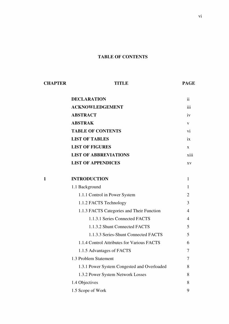
TABLE OF CONTENTS
CHAPTER TITLE PAGE
DECLARATION ii
ACKNOWLEDGEMENT iii
ABSTRACT iv
ABSTRAK v
TABLE OF CONTENTS vi
LIST OF TABLES ix
LIST OF FIGURES x
LIST OF ABBREVIATIONS xiii
LIST OF APPENDICES xv
1 INTRODUCTION 1
1.1 Background 1
1.1.1 Control in Power System 2
1.1.2 FACTS Technology 3
1.1.3 FACTS Categories and Their Function 4
1.1.3.1 Series Connected FACTS 4
1.1.3.2 Shunt Connected FACTS 5
1.1.3.3 Series-Shunt Connected FACTS 5
1.1.4 Control Attributes for Various FACTS 6
1.1.5 Advantages of FACTS 7
1.3 Problem Statement 7
1.3.1 Power System Congested and Overloaded 8
1.3.2 Power System Network Losses 8
1.4 Objectives 8
1.5 Scope of Work 9

vii
1.6 Project Report Organization 9
2 LITERATURE REVIEW 11
2.1 Introduction 11
2.2 Reactive Power Loss Sensitivity Indices Method 11
2.3 Real Power Flow Sensitivity Indices Method 12
2.4 Line Sensitivity Indices Method 13
2.4 Summary 14
3 MODELING AND THEORY 15
3.1 Introduction 16
3.2 Characteristic of TCSC 16
3.3 Static Modeling of TCSC 18
3.4 Optimal Placement of TCSC 20
3.5 Advantages of TCSC 21
3.6 Summary 21
4 METHODOLOGY 23
4.1 Introduction 23
4.2 Software Overview 24
4.2.1 Power World Simulator 18 GSO 25
4.2.2 MATLAB/MATPOWER 5.0 25
4.3 System under Study 26
4.3.1 Test Case 1: 5 Bus System 26
4.3.2 Test Case 2: Modified IEEE 14 Bus System 27
4.4 Project Flow Chart 27
4.5 Summary 30
5 RESULT AND DISCUSSION 31
5.1 Introduction 31
5.2 Congestion Management for 5 Bus System 31
5.2.1 TCSC at Optimal Location, Line 3-5 32
5.2.2 TCSC at Random Location 33

viii
5.3 Transmission Line Loadability for 5 Bus System 39
5.3.1 TCSC at Optimal Location, Line 3-5 39
5.3.2 TCSC at Random Location 40
5.4 Reactive Power Losses Reduction for 5 Bus System 45
5.4.1 TCSC at Optimal Location, Line 3-5 46
5.4.2 TCSC at Random Location 47
5.5 Congestion Management for IEEE 14 Bus System 51
5.5.1 TCSC at Optimal Location, Line 2-5 52
5.5.2 TCSC at Random Location 54
5.6 Transmission Line Loadability for IEEE 14 Bus System 58
5.6.1 TCSC at Optimal Location, Line 2-5 58
5.6.2 TCSC at Random Location 59
5.7 Reactive Power Losses Reduction for IEEE 14 Bus 64
5.7.1 TCSC at Optimal Location, Line 2-5 64
5.7.2 TCSC at Random Location 65
5.8 Discussion 70
5.8.1 5 Bus System 70
5.8.2 Modified IEEE 14 Bus System 72
5.9 Summary 74
6 CONCLUSION 75
6.1 Conclusion 75
6.2 Future Work 75
REFERENCES 76
Appendices A-C 78

ix
LIST OF TABLES
TABLE NO. TITLE PAGE
1.1 Control Attributes for Various FACTS Controller 6
4.1 Sensitivity Index and Line Reactance Parameters
for 5 Bus System 29
4.2 Sensitivity Index and Line Reactance Parameters
for Modified IEEE 14 Bus System 29
5.1 Reactive Power Loss Sensitivity Index for 5 Bus System 70
5.2 Summary of Line Congestion for 5 Bus System 71
5.3 Summary of Line Loadability for 5 Bus System 71
5.4 Overall Summary with TCSC at Line 3-5 72
5.5 Reactive Power Loss Sensitivity Index for
IEEE 14 Bus System 72
5.6 Summary of Line Congestion for IEEE 14 Bus System 73
5.7 Summary of Line Loadability for IEEE 14 Bus System 73
5.8 Overall Summary with TCSC at Line 2-5 73
x
LIST OF FIGURES
FIGURE NO. TITLE PAGE
1.1 Illustration of Controllability Power System 3
1.2 FACTS Categories 4
1.3 Series Connected FACTS 5
1.4 Shunt Connected FACTS 5
1.5 Combined Series-Shunt Connected FACTS 6
3.1 Basic Diagram of TCSC 15
3.2 Characteristic of TCSC 17
3.3 Model of Transmission Line 18
3.4 Model of Transmission Line with TCSC 19
3.5 Injection Model of TCSC 20
4.1 Overall Project Flow 24
4.2 5 Bus System 26
4.3 Modified IEEE 14 Bus System 27
4.4 Optimal Placement of TCSC Flowchart 28
4.5 Sample of M-file for Modified IEEE 14 Bus System 28
4.6 Line Parameter in Power World 30
5.1 Base Case Scenario for 5 Bus System 32
5.2 Congestion Management: 20% TCSC at Line 3-5 33
5.3 Congestion Management: 50% TCSC at Line 3-5 33
5.4 Congestion Management: 20% TCSC at Line 4-5 34
5.5 Congestion Management: 50% TCSC at Line 4-5 34
5.6 Congestion Management: 20% TCSC at Line 2-5 35
5.7 Congestion Management: 50% TCSC at Line 2-5 35
5.8 Congestion Management: 20% TCSC at Line 2-3 36
5.9 Congestion Management: 50% TCSC at Line 2-3 36
xi
5.10 Congestion Management: 20% TCSC at Line 1-2 37
5.11 Congestion Management: 50% TCSC at Line 1-2 37
5.12 Congestion Management: 20% TCSC at Line 1-4 38
5.13 Congestion Management: 50% TCSC at Line 1-4 38
5.14 Line Loadability without TCSC 39
5.15 Loadability with 20% Compensation at Line 3-5 40
5.16 Loadability with 50% Compensation at Line 3-5 40
5.17 Loadability with 20% Compensation at Line 4-5 41
5.18 Loadability with 50% Compensation at Line 4-5 41
5.19 Loadability with 20% Compensation at Line 2-5 42
5.20 Loadability with 50% Compensation at Line 2-5 42
5.21 Loadability with 20% Compensation at Line 2-3 43
5.22 Loadability with 50% Compensation at Line 2-3 43
5.23 Loadability with 20% Compensation at Line 1-2 44
5.24 Loadability with 50% Compensation at Line 1-2 44
5.25 Loadability with 20% Compensation at Line 1-4 45
5.26 Loadability with 50% Compensation at Line 1-4 45
5.27 System Reactive Power, Q Loss without TCSC 46
5.28 Reactive Power, Q Loss with 20%TCSC at Line 3-5 46
5.29 Reactive Power, Q Loss with 50%TCSC at Line 3-5 47
5.30 Reactive Power, Q Loss with 20%TCSC at Line 4-5 47
5.31 Reactive Power, Q Loss with 50%TCSC at Line 4-5 48
5.32 Reactive Power, Q Loss with 20%TCSC at Line 2-5 48
5.33 Reactive Power, Q Loss with 50%TCSC at Line 2-5 48
5.34 Reactive Power, Q Loss with 20%TCSC at Line 2-3 49
5.35 Reactive Power, Q Loss with 50%TCSC at Line 2-3 49
5.36 Reactive Power, Q Loss with 20%TCSC at Line 1-2 50
5.37 Reactive Power, Q Loss with 50%TCSC at Line 1-2 50
5.38 Reactive Power, Q Loss with 20%TCSC at Line 1-4 50
5.39 Reactive Power, Q Loss with 50%TCSC at Line 1-4 51
5.40 Transmission Line with Severe Power Losses 51
5.41 Modified IEEE 14 Bus Base Case Scenario 52
5.42 IEEE 14 Bus with 20% TCSC at Line 2-5 53
5.43 IEEE 14 Bus with 50% TCSC at Line 2-5 53

xii
5.44 IEEE 14 Bus with 20% TCSC at Line 2-4 54
5.45 IEEE 14 Bus with 50% TCSC at Line 2-4 54
5.46 IEEE 14 Bus with 20% TCSC at Line 1-5 55
5.47 IEEE 14 Bus with 50% TCSC at Line 1-5 55
5.48 IEEE 14 Bus with 20% TCSC at Line 1-2 56
5.49 IEEE 14 Bus with 50% TCSC at Line 1-2 56
5.50 IEEE 14 Bus with 20% TCSC at Line 2-3 57
5.51 IEEE 14 Bus with 50% TCSC at Line 2-3 57
5.52 Line Loadabilty without TCSC 58
5.53 Loadability with 20% Compensation at Line 2-5 59
5.54 Loadability with 50% Compensation at Line 2-5 59
5.55 Loadability with 20% Compensation at Line 2-3 60
5.56 Loadability with 50% Compensation at Line 2-3 60
5.57 Loadability with 20% Compensation at Line 2-4 61
5.58 Loadability with 50% Compensation at Line 2-4 61
5.59 Loadability with 20% Compensation at Line 1-5 62
5.60 Loadability with 50% Compensation at Line 1-5 62
5.61 Loadability with 20% Compensation at Line 1-2 63
5.62 Loadability with 50% Compensation at Line 1-2 63
5.63 System Reactive Power, Q Loss for Base Case Scenario 64
5.64 Reactive Power, Q Loss at Line 2-5 with 20%TCSC 65
5.65 Reactive Power, Q Loss at Line 2-5 with 50%TCSC 65
5.66 Reactive Power, Q Loss at Line 2-4 with 20%TCSC 66
5.67 Reactive Power, Q Loss at Line 2-4 with 50%TCSC 66
5.68 Reactive Power, Q Loss at Line 2-3 with 20%TCSC 67
5.69 Reactive Power, Q Loss at Line 2-3 with 50%TCSC 67
5.70 Reactive Power, Q Loss at Line 1-5 with 20%TCSC 68
5.71 Reactive Power, Q Loss at Line 1-5 with 50%TCSC 68
5.72 Reactive Power, Q Loss at Line 1-2 with 20%TCSC 69
5.73 Reactive Power, Q Loss at Line 1-2 with 50%TCSC 69
5.74 Summary of Reactive Power Loss for 5 Bus System 71
5.75 Summary of Reactive Power Loss for IEEE 14 Bus System 73
xiii
LIST OF ABBREVIATIONS
FACTS - Flexible AC Transmission System
UPFC - Unified Power Flow Control
TCR - Thyristor Controlled Reactor
TCSR - Thyristor Controlled Switched Reactor
SVC - Static VAR Compensator
TCSC - Thyristor Controlled Series Capacitor
TSSR – Thyristor Controlled Switched Series Reactor
TCBR – Thyristor Controlled Brakening Reactor
TCVR - Thyristor Controlled Voltage Reactor
TCVL - Thyristor Controlled Voltage Limiter
TSSC - Thyristor Controlled Switched Series
TC‐PAR - Thyristor Controlled Phase Angle Regulator
TC‐PST - Thyristor Controlled Phase Shift Transformer
SSSC - Static Synchronous Series Compensator
STATCOM - Static Synchronous Compensator
UPFC - Unified Power Flow Controller
HPFC - Hybrid Power Flow Controller
HVDC - High Voltage Direct Current
PSS - Power System Stabilizers
AP - Active Power
RP - Reactive Power
VSC - Voltage Source Converter
VSI - Voltage Source Inverter
VS - Voltage Stability
VI - Voltage Instability
VC - Voltage Collapse
VP - Voltage Profile

xiv
VR - Voltage Regulation
SSVS - Steady State Voltage Stability
TS - Transient Stability
APTC - Available Power Transfer Capacity
PQ - Power Quality
SSR - Sub‐synchronous Resonance
OPF - Optimal Power Flow
POD - Power Oscillation Damping
DGs - Distributed Generations
SS - Steady State
FCL - Fault Current Limiting

xv
LIST OF APPENDICES
APPENDIX TITLE PAGE
A Modified IEEE 14 Bus System Data 78
B Modified IEEE 14 Generator Data 79
C Modified IEEE 14 Branch Data 80

1
CHAPTER 1
INTRODUCTION
1.1 Background
Over the coming years and decades, the power generation industry faces and
intimidating challenge in the meeting of energy demands of the global need of
electrical energy. Current scenarios of electric power industries had altered the
operational strategy and management of utilities in many aspects. In years future,
expected the electricity demand and usage will double globally or triple in
developing countries. Financial and market forces are, and will continue to, demand
a more optimal and profitable operation of the power system with respect to
generation, transmission, and distribution [1]. Thus, ensuring continuous and reliable
power generation have become crucial and one of the biggest barriers to reliable
power generation is ability to maintain system security which is avoiding congestion
in transmission lines as well have maintaining optimum line load ability and
minimum system power losses.
The existing of network power system might not able to stand the entire new
scenario for electricity trades. This is further endangered by relatively decline in
transmission expansion due to requirement of huge investment couples with the
problems in acquiring right of way for the new transmission facilities and concerns
towards environment and cost [2]. Furthermore, due to security concerns, it will not
be a good solution for the generation company to drop a certain load in order to
maintain power system security which is actually may result them penalties. Plus
with various environmental and regulatory concerns, expansion of the power

2
facilities is restricted in some countries. Thus, it would be very beneficial to the
world if we could tackle all the security issue which in results can delay the
construction of new transmission line and also maintaining system security, stability
and reliability in current emerging electricity market scenario. Because of all that, it
becomes very important to improve line security and load ability along the
transmission line to meet the requirement. With recent growth of power electronics
devices, flexible AC transmission system known as FACTS is introduced in power
system as a promising pattern for future growth of power system. These FACTS
devices are capable to control power flow over the lines with optimum load ability
and small power losses.
1.1.1 Control in Power System
Power system consists of three main components which are generation,
transmission and distribution. Although power electronic based equipment is
prevalent in each of these three areas, such as with static excitation systems for
generators and custom power equipment in distribution systems [1, 3], we often
observed the major power system constraints are accompanying in transmission
system when transfer an amount of power from generator to where it is utilized. In
today world, transmission systems are struggling to works as close as possible to
their stability limits which at the same time maintaining quality of the power
delivered. The transmission constraints may involve power deliver between a single
area or more. Each of the transmission constraint may have one or more of system
level complications such as congestion, high power system losses, minimum power
transfer, voltage stability and quality and many others. The key to solve these
problems is by controlling some of parameters of power system.
Figure 1.1 illustrates controllability of the power system in which will be
impacted by controlling the power-angle curve. There are three main parameters that
play a major role in power system control which are voltage, angle and impedance.
The illustration demonstrates the point where this three main variables that in being
controlled to influence its recital.

3
Figure 1.1: Illustration of Controllability Power System [1]
1.1.2 FACTS Technology
The concept of Flexible AC transmission system has been proposed in 1995,
which best known as FACTS. The basic idea of FACTS is installing the power
electronic devices at the high-voltage side of the power grid to make the whole
system electronically controllable [9]. FACTS controller which are built from power
electronic devices demonstrates capability control the voltage, power flow, stability a
power system. There are few configurations to connect FACTS devices in
transmission line which are in shunt, series or a combination of shunt and series. The
definition and characterization of various FACTS devices are described in references
[4, 5, 6]. FACTS devices are very effective and capable of increasing the power
transfer capability of a line, insofar as thermal limits permit, while maintaining the
same degree of stability [4, 7, 8].

4
1.1.3 FACTS Categories and Their Function
The FACTS devices have the capability to control real and reactive power to
the power network in very fast manner. Basically, the FACTS can be best categories
into two generations as describes in Figure 1.2 and have a four basic classification of
their connection like series connected, shunt connected and combine both series and
shunt connected.
Figure 1.2: FACTS Categories [9]
1.1.3.1 Series Connected FACTS
Series FACTS devices as illustrated in Figure 1.3 could be variable
impedance, such as capacitor, reactor, etc., or power electronics based variable
source of main frequency, sub synchronous and harmonic frequencies (or a
combination) to serve the desired need. In principle, all series FACTS devices inject
voltage in series with the transmission line.
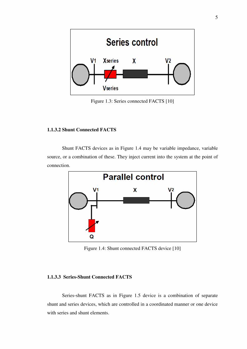
5
Figure 1.3: Series connected FACTS [10]
1.1.3.2 Shunt Connected FACTS
Shunt FACTS devices as in Figure 1.4 may be variable impedance, variable
source, or a combination of these. They inject current into the system at the point of
connection.
Figure 1.4: Shunt connected FACTS device [10]
1.1.3.3 Series-Shunt Connected FACTS
Series‐shunt FACTS as in Figure 1.5 device is a combination of separate
shunt and series devices, which are controlled in a coordinated manner or one device
with series and shunt elements.

6
Figure 1.5: Series -Shunt connected FACTS device [10]
1.1.4 Control Attributes for Various FACTS
The Control Attributes for Various FACTS Controllers are shown in Table 1.1.
Table 1.1: Control Attributes for Various FACTS Controller
No FACTS Controller Control Attributes
1 SVC, TCR, TCS, TRS Voltage control, VAR compensation, POD,
VS, TS and DS
2 TCSC, TSSC Current Control, POD, VS, TS, DS and
FCL
3 TCSR, TSSR Current Control, POD, VS, TS, DS and
FCL
4 TC-PST or TC-PAR AP control, POD, VS, TS and DS
5 TCBR POD, TS and DS
6 TCVL Transient and dynamic voltage limit
7 TCVR RP control, voltage control, POD, VS, TS
and DS
8 SSSC without storage Current Control, POD, VS, TS, DS and
FCL
9 SSSC with storage Current Control, POD, VS, TS, DS and
FCL
10 STATCOM without storage Voltage control, VAR compensation, POD
and VS
11 STATCOM with storage,
BESS, SMES, large DC
capacitor
Voltage control, VAR compensation, POD,
VS, TS and DS, AGC
12 UPFC AP and RP control, voltage control, VAR
compensation, POD, VS, TS and DS, FCL
13 IPFC RP control, voltage control, POD, VS, TS
and DS

7
1.1.5 Advantages of FACTS
FACTS devices have become very popular in the recent power system world
due to their following benefit benefits:
(i) Provide power flow control to meet the power system needs by
ensuring optimum power flow, mitigate emergency conditions, or a
combination of them;
(ii) Increase the loading capability of lines to their thermal capabilities,
including short term and seasonal demands;
(iii) Enhance power system reliability and efficiency;
(iv) Eliminate construction of new transmission lines;
(v) Added flexibility in siting new generation;
(vi) Provide secure tie‐line connections to neighboring utilities and
regions thereby decreasing overall generation reserve requirements on
both sides;
(vii) Upgrade of transmission lines;
(viii) Increased system security; and
(ix) Loop flow control.
1.2 Problem Statement
As stated in earlier section, increasing dependency of electrical energy has
led to rapid growth of power system which results to few uncertainties. Power
disruption and individual power outage one of the major problem affect the economy
of the country. If the exchanges were not controlled, some lines located on particular
paths may become overloaded or congested. And it even worse if uncontrollable
reactive power losses results to instability to maintain the voltage at all the buses
around the nominal value lead to voltage collapse.

8
1.2.1 Power System Congested and Overloaded
Transmission line overloaded or congested occurs when there is not enough
transmission capacity to simultaneously accommodate all requests for transmission
service within a region [11]. Restructuring and growth of energy industry has moved
into competitive market which indirectly causing uncontrolled power delivery in
transmission system. This difficulty and problem is exacerbating by the increase of
the amount of congestion cause by increase of commercial transmission and the
relative decline of total power delivery.
1.2.2 Power System Network Losses
In the energy system, the power generated at power stations is going through
a large and complex network before reaching the end user. During power delivering
and transmission process, some percentage of this power in the distribution network
will be lost. Controlling the power flow in the network system either under normal or
contingency conditions network can help to mitigate the heavily loaded and reduce
system power loss, and so it will improve the stability and performance of the system
without power interuption [12] [13].
1.3 Objectives
This master project was conducted with the objective to determine the
effective location to install FACTS controller in the studied power system bus
network. The effective location of TCSC is identifying to achieve the following
target:
(i) To optimize location of TCSC using sensitivity based method;
(ii) To mitigate contingencies in transmission system;
(iii) To increase transmission line load ability; and
(iv) To reduce overall system power losses.

9
1.4 Scope of Work
Among available FACTS controller, this master project was scope down to
Thyristor Control Series Capacitor (TCSC) only in which to study the effect of this
FACTS controller in managing congestion, line loadability and reactive power losses
in test case of 5 bus system(small network) and modified IEEE 14 bus network
system (large network). This project is adopted reactive power losses indices method
in determining the most sensitive transmission line for optimal placement of TCSC
to the corresponding studied network system. The simulation was carried out with
aid of Power World Simulator 18 GSO and MATLAB/MATPOWER 5.0. This paper
as well investigated the approached method using difference degree of compensation
of TCSC which is 20% compensation over 50% compensation.
1.5 Project Report Organization
This project report is organized in six chapters. Each chapter will discuss
details on the particular topics. Chapter 1 basically outlines the main objectives and
scopes of this research project and in brief addressing the issue of current world
demand of energy and the challenges and opportunities that motivate FACTS
controller’s usage. It generally introduce FACTS devices as best approaches to attain
current power reliability issue in such a way of power quality, transmission
loadability, congestion management, lower losses reduction and voltage stability.
This chapter in brief overviewing the introduction of FACTS technology in power
system how it is important to establish an optimum power reliability, efficiency and
quality in power system network. Provide an overview of various type of FACTS
controller and demonstrates in details the differences in term of structure and
functionality on each FACTS devices.
Chapter 2 illustrates the literature review and several case studies of related
papers and articles by eminent authors in investigating and determining the optimum
and reliable power transfer capability in transmission system. Discussing the

10
propose techniques and approaches used by authors to control real and reactive
power in transmission system.
Chapter 3 describes in details the basic working principle, characteristic and
operation of selected FACTS devices (TCSC) studied in this research. This section
will demonstrate mathematical modelling of TCSC to study the relationship between
electrical transmission system and TCSC in steady state condition.
Chapter 4 highlights in details the methodologies used to model and simulate
the system under study (5 bus system and modified IEEE 14 bus system) with
existence of TCSC in the networks. Provide a general overview of software and
frame works (Power World Simulator and MALLAB/MATPOWER 5.0) used is
modeling corresponding networks system. This chapter illustrates the parameter
setting of TCSC as well as the approach method to find the optimal placement based
on several case studies develop in this research. The details such as flow chart and
schematic diagram are shown in this chapter.
Chapter 5 presents the outcome of the project carried out by result and
discussion obtained in Chapter 5. In this chapter, all the result gets will compare with
among the cases evaluated. Any of gap and findings is highlighted in discussion part.
Chapter 6 presents the final conclusion of this project as well listed out the
recommendation for future development and enhancement.

76
REFERENCES
1. John J. Paserba (2009) How FACTS Controller Benefit AC Transmission
System. Power Systems Conference and Exposition: IEEE.
2. JOHN G. KASSAKIAN (2011). The Future of the Electric Grid. MIT Energy
Initiatives. :MIT EI.
3. N.G. Hingorani (1995). Introducing Custom Power. IEEE Spectrum.
4. N.M. Tabatabaei, Gh. Aghajani, N.S. Boushehri, and S. Shoarinejad (2011).
Optimal Location of FACTS Devices Using Adaptive Particle Swarm
Optimization Mixed with Simulated Annealing, International Journal on IJTPE,
3(7).
5. N.G. Hingorani, L. Gyugyi (2002).Understanding FACTS Concepts and
Technology of Flexible AC Transmission System.Electrical Insulation
Magazine: IEEE Press, 7803-3455-8.
6. A.A. Edris, R. Aapa, M.H. Baker, L. Bohman, and K. Clark (1997), Proposed
Terms and Definitions for Flexible AC Transmission Systems (FACTS), IEEE
Trans. on Power Delivery: IEEE,1848-185.
7. P. Kundur (1994). Power System Stability and Control, EPRI Power System
Engineering Series: McGraw-Hill Inc.
8. P.R. Sharma, A. Kumar, and N. Kumar (2007). Optimal Location for Shunt
Connected FACTS Devices in a Series Compensated Long Transmission Line,
Turk J. Elec. Engin., 15(3).
9. Xunchi Wu, Reactive Power Compensation Based on FACTS Devices. Columbia
Univeristy.
10. Dr Ahmed Massoud, FACTS, Flexible Alternating AC Transmission System,
University of Strathclyde.
11. C. Martinez, and A. Rodriguez (2002). Congestion Management Requirements,
Methods and Performance Indices, Electric Power Group, Southern California
Edison.
12. A Hemasekhar, and Dr. A Lakshmi Devi (2014). Enhancement of voltage profile
and reduce power system losses by using FACTS devices, International Journal
of Conceptions on Electrical and Electronics Engineering, 2(1), 2345-9603.
77
13. F.D. Galiana, K. Almeida, M. Toussaint, J. Griffin, and D. Atanackovic (1996),
Assessment and Control of the Impact of FACTS Devices on Power System
Performance, IEEE Trans. Power Systems, 11(4).
14. Madhura Gad, Prachi Shinde, and Prof. S.U.Kulkarni (2012). Optimal Location
of TCSC by Sensitivity Methods, International Journal Of Computational
Engineering Research, 2(6),
15. Abouzar Samimi, and Peyman Naderi (2012). A New Method for Optimal
Placement of TCSC Based on Sensitivity Analysis for Congestion Management.
Smart Grid and Renewable Energy, 3, 10-16.
16. Renu Yadav, Sarika Varshney, and Laxmi Srivastava (2011). Enhancement of
Voltage Stability through Optimal Placement of TCSC, International Journal of
Power System Operation and Energy Management, 1(2), 2231–4407.
17. Anwar S. Siddiqui, Rashmi Jain, Majid Jamil and Gupta C. P. (2011). Congestion
Management in High Voltage Transmission Line using Thyrister Controlled
Series Capacitors, Journal of Electrical and Electronics Engineering Research,
3(8), 2141- 2367. Academic Journals.
18. Naresh Acharya, N. Mithulananthan (2006).Locating series FACTS devices for
congestion management in deregulated electricity markets. Electric Power
Systems Researc: ScienceDirect, 352–360.
19. Seyed Abbas Taher, and Hadi Besharat, (2008). Transmission Congestion
Management by Determining Optimal Location of FACTS Devices in
Deregulated Power Systems. American Journal of Applied Science, 5(3), 242-
247. American Journal.
20. L.Rajalakshmi, M.V.Suganyadevi, and S.Parameswari (2011). Congestion
Management in Deregulated Power System by Locating Series FACTS Devices.
International Journal of Computer Applications, 13(8), 0975-8887.
21. A.Yazdanpanah-Goharrizi and R.Asghari (2007). A Novel Line Stability Index
(NLSI) for Voltage Stability Assessment OF Power Systems, 7th WSEAS
International Conference on Power Systems, September 15-17, Beijing, China.