EFFECTIVE LENGTH OF · PDF fileEFFECTIVE LENGTH FACTORS FOR SOLID ROUND CHORD MEMBERS OF...
118
EFFECTIVE LENGTH FACTORS FOR SOLID ROUND CHORD MEMBERS OF GUYEDTOWERS A Thesis Submined to the Coilege o f Graduate Studies and Research through Civil & Environmental Engineering in Partial Fulfillment of the Requirements for the Degree o f Master of Applid Science at the University of Windsor Windsor, Ontario, Canada 1999
Transcript of EFFECTIVE LENGTH OF · PDF fileEFFECTIVE LENGTH FACTORS FOR SOLID ROUND CHORD MEMBERS OF...

EFFECTIVE LENGTH FACTORS FOR SOLID ROUND CHORD MEMBERS OF
GUYEDTOWERS
A Thesis Submined to the Coilege of Graduate Studies and Research
through Civil & Environmental Engineering in Partial Fulfillment of the Requirements for
the Degree of Master of Applid Science at the University of Windsor
Windsor, Ontario, Canada
1999

National Library 1*1 of Canada Bibliothèque nationale du Canada
Acquisitions and Acquisitions et Bibliographie Services services bibliographiques 395 Wellington Street 395. rue WeilingtOII OttawaON K l A W OltawaON K 1 A W canada canada
The axthor has granted a non- exclusive licence aliowing the National Library of Canada to reproduce, loan, distribute or sell copies of this thesis in microform, paper or electronic formats.
L'auteur a accordé une licence non exclusive permettant a la Bibliothèque nationale du Canada de reproduire, prêter, distribuer ou vendre des copies de cette thèse sous la forme de microfiche/film, de reproduction sur papier ou sur format électronique.
The author retains ownership of the L'auteur conserve la propriété du copyright in this thesis. Neither the droit d'auteur qui protège cette thèse. thesis nor substantial extracts fiom it Ni la thèse ni des extraits substantiels may be printed or otherwise de celle-ci ne doivent être imprimés reproduced without the author's ou autrement reproduits sans son permission. autorisation.


Chord mernbes of twenty-five dl-welded guyed-latticed communication steel tower
sections were tested in the Structurai Engineering Laboratory of the University of
Windsor to detemine the effective length factors of the chord memben. Two diffaent
manufacturers, viz., Pirod Inc., Plymouth, Indiana, and ERI Inc., Chandler, Indiana,
provided the test specimens. Ali tower sections were fabricated fiom solid round
members and were trimgular in cross section. Tower sections provided by ER1 were 4.57
m (1 5.0 fi.) long with continuous diagonal bracings welded to the chord members, while
those provided by Pirod were 6-09 m (20.0 A.) long with the diagonal bracings cut and
welded to the chord members. The diameters of the chord members varied fiom 38.1 mm
(1.5 in.) to 69.85 mm (2.75 in.) while the diameters of the diagonal bracings varïed fiom
12.7 mm (0.5 in.) to 22.3 mm (0.875 in.).
The tower sections were tested in a horizontal position. One chord member of the tower
was cut and tested by applying a load at its center while the diagonal bracings remained
attached to the chord members. Deflections were recorded manually while the applied
Ioad was recorded using a data acquisition system. The load-deflection data were used to
calculate the effective length factors for the chord members which were found to be
varying from 0.95 to 0.99. Good agreement was observed between the expenmental
deflections at the center of the chord member and those obtained fiom the cornputer
anal ysis software package ABAQUS.
The stiffness contribution of diagonal bracings to the ends of the chord members was also
computed numerically by structural analysis package STAADmro and the effkctive
length factors were calculated using the equilibrium equation given by the structural
stability research council (SSRC, 1976). The effective length factor dculated by this
rnethod varkd h m 0.93 to 0.99. Based on the experimental and numerical results, it
appears reasonable to assume an effective length factor of 1 .O in actual design practice.
DEDICATED TO MY
LOVING PARENTS DR. ABDUL W I M QURESHI
AND DR. SAKINA QURESHI

First of dl , the author expresses his most sincere gratitude to Aimighty G d without
Whose help nothing would have been possible.
The author wishes to express his deep appreciation and gratitude to his Principal Advisor
Dr. Murty K. S. Maduguk Professor, Department of Civil and Environmental
Engineering, for his constant guidance, c~pe ra t i on and encouragement dunng the entire
process of this research. To him I say, "Thank you very much".
Special hanks are also reserved for the Co-Advisor Dr. Sudip Bhattacharjee, Assistant
Professor, Deparmient of Civil and Enviro~lmental Engineering, for his valuable
suggestions and supe~s ion during the whole process of this work.
The author is also thankful to Pirod Inc. and ER1 Inc. for providing the test specimens
used in this investigation.
Thanks are also reserved for the technicians Richard Clark, Lucian Pop and Patrick
Seguin for their vital help during the experimental part of this project.
The author also acknowledges the help provided by his fiiends and colleagues Messrs.
Zonghua Chen, Yongcong Ding, Robert Rea and Yean Sun. The support provided by the
vii

Information Technology services of the University of Windsor including the services of
the CADICAM laboratory are also greatly appreciated.
The financial support provided by the Department of Civil and Environmental
Engineering, University of Windsor, and the Natural Sciences and Engineering Research
Council of Canada is gratefûlly acknowiedged.
In the end the author also feels very much obliged and indebted to al1 of his family
members who provided continued mord and financial support during this whole period
of study and research at the University of Windsor.
viii

TABLE OF CONTENTS
ABSTRACT
DEDICATION
ACKNOWLEDGEMENTS
LIST OF TABLES
LIST OF FIGURES
NOTATION
iv
vi
vii
xi
xii
XV
CaAPTER ONE - INTRODUCTION
..1 GENERAL 1
. .2 CLASSIFICATION OF COMMUNICATION TOWERS 1
. .3 STRUCTURAL CONFIGURATION 4
. .4 NEED FOR INVESTIGATION 5
. .5 OBJECTIVE OF THE PRESENT RESEARCH 6
..6 OUTLINEOFTHETHESIS 6
CEIAPTER 'IWO - BACKGROUND OF RESEARCH AND REVIEW OF LITERATWRE
2.1 GENERAL 8 2.2 JOINT EFFECT IN TRANSMISSION TOWERS 9 2.3 EFFECTIVE LENGTH FACTOR IN BRACED FRAMES IO 2.4 THE G-FACTOR AND EFFECTIVE LENGTHS OF
COLUMNS 13 2.5 CODES, STANDARDS AND SPECIFICATIONS 16
2.5.1 CSA S37-94 "ANTENNAS, TOWERS, AND ANTENNA-SUPPORTING STRUCTUREStt 16
2.5.2 CAN/CSA-S16.1-94 "LIMIT STATES DESIGN OF STEEL STRUCTURES" 16
2.5.3 AISC - LRFD "LOAD AND RESISTANCE FACTOR DESIGN SPECIFICATION FOR STRUCTURAL STEEL BUILDINGS" 17
2.5.4 EUROCODE 3: PART 3.1 : 1997 "DESIGN OF STEEL STRUCTURES TOWERS, MASTS AND CKIMNEYS - TOWERS AND MASTS" 20
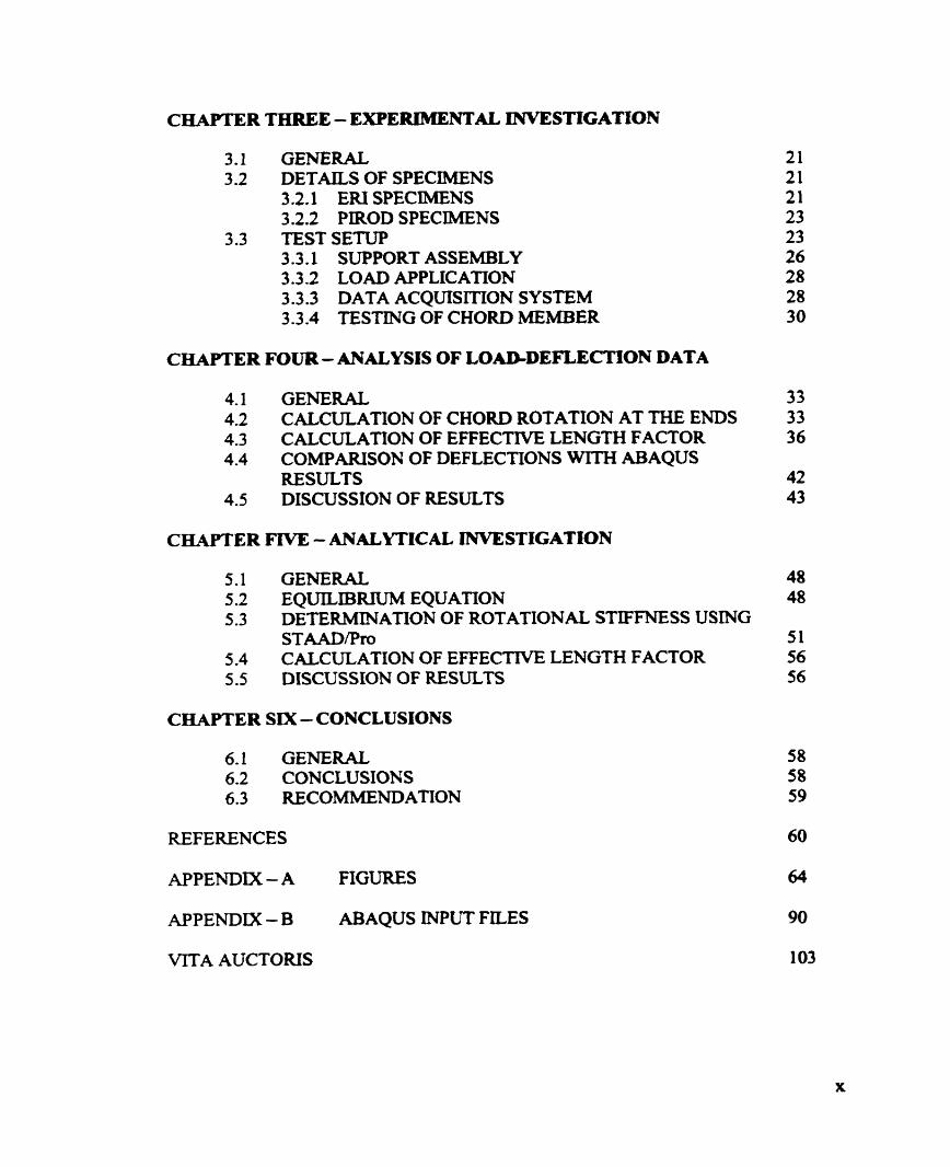
CHAPTER THREE - EXPERIMENTAL INVESTIGATION
3.1 GEBERAL 3.2 DETAILS OF SPECIMENS
3.2.1 E N SPECIMENS 3.2.2 PIROD SPECIMENS
3.3 TESTSETUP 3.3.1 SUPPORT ASSEMBLY 3.3.2 LOAD APPLICATION 3.3.3 DATA ACQUISITION SYSTEM 3.3.4 TESTING OF CHORD MEMBER
CHAPTER FOUR - ANALYSIS OF LOAD-DEFLEC'MON DATA
4.1 GENERAL 33 4.2 CALCULATION OF CHORD ROTATION AT THE ENDS 33 4.3 CALCULATION OF EFFECTTVE LENGTH FACTOR 36 4.4 COMPARISON OF DEFLECTIONS WITH ABAQUS
RESULTS 42 4.5 DISCUSSION OF RESULTS 43
CHAPTER FlVE - ANALYTICAL INVESTIGATION 5.1 GENERAL 48 5.2 EQUILIBIUUM EQUATION 48 5.3 DETERMINATION OF ROTATIONAL STIFFNESS USING
STAADPro 5 1 5.4 CALCULATION OF EFFECTTVE LENGW FACTOR 56 5.5 DISCUSSION OF RESULTS 56
CHAPTER SIX - CONCLUSIONS
6.1 GENERAL 6.2 CONCLUSIONS 6.3 RECOMMENDATION
REFERENCES 60
APPENDTX - A FIGURES 64
APPENDIX - B ABAQUS INPUT FILES 90
VITA AUCTORIS 1 03
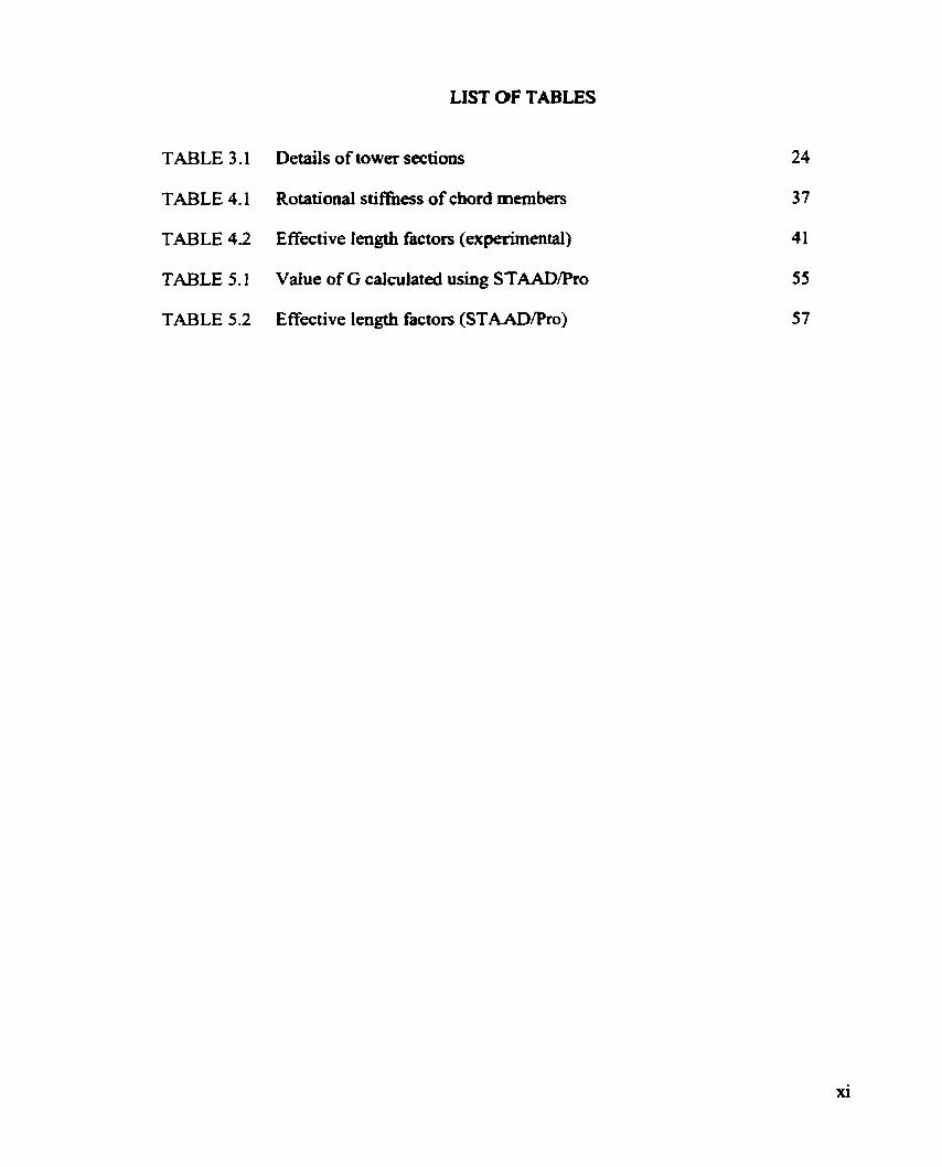
LIST O F TABLES
TABLE 3.1 Details of tower sections
TABLE 4.1 Rotational stiffiness of chord members
TABLE 4.2 Effective Iength factors (experimental)
TABLE 5.1 Vaiue of G calculated using STAADPro
TABLE 5.2 Effective length factors (STAADPro)

LIST OF FIGURES
Self-supporting tower
Guyed Tower
Efiective Length Factors for six idealued conditions
Nomograph
ERI Tower - Weld anangement
Pirod Tower - Weld arrangement
P i r d Towers lying in the laboratory
Chord member cut and loaded
Test setup
Test setup showing the loading coiumn and the suppon assembly
Data acquisition system
Chord member fixed at both ends
Free body diagram of a coium.
Mode1 generated by ABAQUS
Graphical comparison for deflections of specimen - S- 1 (A)
Graphical comparison for deflections of specimen - S-3 (A)
Graphical comparison for deflections of spefimen - S-5 (A)
Framed structure
Buckling of a colunin in a h e d Structure
Tower mode1 generated using STAAD/Pro
Section of tower talcen out for analysis
xii

Moment applied on tower joint
Rotation of tower joint
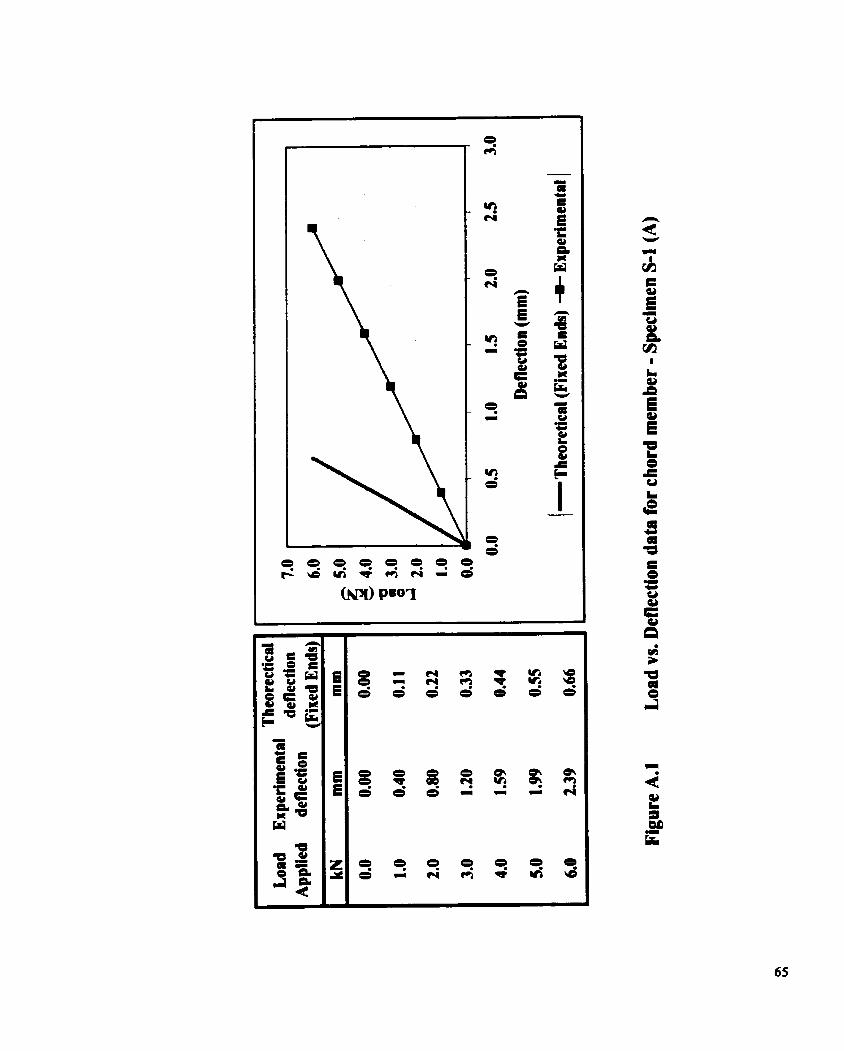
Load vs. Deflection &ta for chord member - Specimen S-1 (A)
Load vs. Deflection daia for chord member - Specimen S-1 (B)
Load vs. Deflection &ta for chord member - Specimen S-2 (A)
Load vs. Deflection data for chord member - S p e c b S-2 (B)
Load vs. Deflection &ta for chord member. - Specimen 5-2 (C)
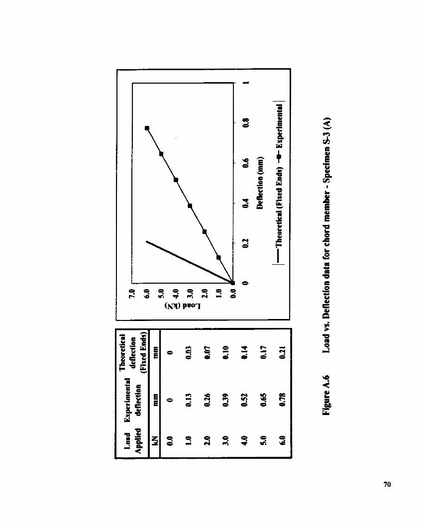
Load vs. Deflection data for chord m e m k - Specimen S-3 (A)
Load vs. Deflection data for chord member - Specimen S-3 (B)
Load vs. Deflection &ta for chord member - Specimen S-4 (B)
Load vs. Deflection data for chord mernber - Spechen S 4 (C)
Load vs. Deflection data for chord member - Specimen S-5 (A)
Load vs. Deflection data for chord mernber - Specimen S-5 (B)
Load vs. Deflection data for chord member - Specimen S-5 (C)
Load vs. Deflection data for chod member Specimen S-6 (A)
Load vs. Deflection data for chord member - Specimen S-6 (B)
Load vs. Deflection data for chord member - Specimen S-6 (C)
Load vs. Deflection data for chord member - Specimen Pl (A)
Load vs. Deflection data for chord member - Specirnen P l (B)
Load vs. Deflection data for chord rnember - Specimen P2 (B)
Load vs. Deflection data for chord member - Specimen P3 (A)
Load vs. Defiection grapii for chord rnember - Specimen P3 (B)

A.2 1 Load vs. Defîection &ta for cbord member - Specimen P4 (A)
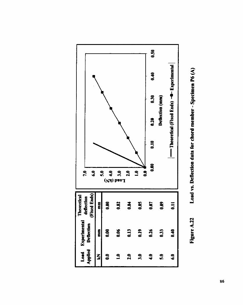
A.22 Load vs. Deflection &ta for chord mernber - Spechen P6 (A)
A.23 Load vs. Deflection &ta for chord member - Specimen P6 (B)
A.24 Load vs. Deflection data for chord member - Specimen P8 (A)
A.25 Load vs. Deflection data for chord member 4pecimen P8 (B)
xiv

NOTATION
Cross-sectional area
Uniformly distributed loaded length
Diameter of cross section
Young's modulus of elasticity
Relative joint stiffiiess ratio, lower
Relative joint stifniess ratio, upper
Moment of inertia
Moment of inertia of column/chord member
Moment of inertia of girderldiagonal bracing
Effective length factor
Panel length of column
Length of girder
Moment at ends of chord member
Fixed end moment
Restraining Moment
Concentrated load applied
intensity of load applied
Difierence in Deflection
Experimental deflection
Calculated Deflection
Angle of Rotation

CIiAPTER ONE
INTRODUCTION
1.1 GENERAL
With the world entering into the 21" century, the demand for an effective and useful
telecommunication system is pwing. This need has resulted in an increase in the
production and developmcnt of telecommunication tools. Some of these
telecommunication tools are mobile phones and pagen. To transmit and receive the
signals properly, antennas are use& which are either parabolic or pole type. These
antennas are usually mounted on steel communication towers.
1.2 CLASSIFICATION OF COMMUNICATION TOWERS
From the structural point of view, communication towers can be classified into three
types :
(a) Monopoles, which are cantilevered tubes with heights up to 70 m,
@) Self-supporting towers (Figure 1.1), commoniy used for heights up to 120 m, and
(c) Guyed towers ( F i p e 1.2) which have been utilized for taller structures up to 620 m.

Figure 1.1 Self-supporting tower
(Source: Pirod inc.)
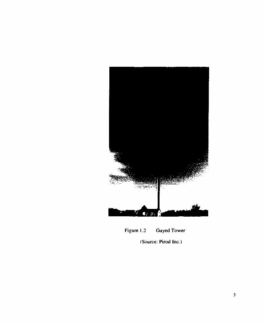
Figure 1 -2 Guyed Tower
(Source: Pirod inc.)
Guyed towers require more land area than the self-supporting ones. This is because of the
guys that provide lateral support to the structure. These guys are steel cabla made
especially for this purpose. They are hooked up fimily with guy anchors that are
anchored in the nearby land, thus occupying a huge surmunding area. Because of this
disadvantage, guyed towers are generally not recommended for installation in densely
populated residential areas or such places where availability of adequate space is a
problem. Usually the nurnber of guy levels holding a tower ranges h m three to five
(Wahba, 1999).
1.3 STRUCTURAL CONFIGURATION
A guyed tower consists of a mast usually of a constant ûiangular cross section. These
towers have a latticed structure with al1 the joints welded or bolted. The triangular mast
of a guyed tower has three vertical members (chords). These chord members are welded
or bolted with horizontals and diagonals (bracing) to form a latticed structure. Al1 the
members are usually solid rounds with varying diameters. Tubes and angles are also
sometimes used for these chords and bracings.
A guyed toww is fabricated in sections and is erected by mounting these sections one on
top of the other in the field by a special method used to build ta11 communication
structures with antennas fixed on it. Helicopters are also occasionally used to carry out
this installation operation.

1.4 NEED FOR INVESTIGATION
The effective length factor of the chord members of triangular guyed-steel-
communication towers is the main topic of this study. To the best of author's knowledge,
most of the e x m e n t a l investigation c e e d out so far on guyed-latticed
communication steel towers, with reference to finding out the effective length factors, is
on cross braced diagonais. So far, no investigation has k e n carried out on solid round
chord members of these towers. Th, there is a strong need to experimentally determine
the effective length factors of chord members that are primary structural components of a
steel communication tower.
Section 6.2 of the Canadian Standards Association S37-94, "Antennas, Towers and
Antenna-Supportïng Structures," (CS A 1 994), deals with members under compression. 1 t
gives the effective length factor for the leg membm of towers as unity. Most practicing
engineers fiequently use this value. However, there are some designers who feel that the
bracing members ptovide rotational rigidity ?O the chord members and so rake the
effective length factor as 0.8.
Thus, there is a need to cany out the experimental investigation of the chord members
and find out the value of the effective length factor. The research is based on the
hypothesis that the diagonal bracings provide rotational ratraint to the chord member
with which they are attacha thus, resulting in an effective length factor which is less
than unity.

1.5 OBJECTIVE OF THE PRESENT RESEARCH
The objective of tbe research is to detexmine, experimentally and theoreticaily, the
effective length factors for solid round chord members of guyed-latticed steel
communication towers.
1.6 OUTILiNE OF THE THESIS
Chapter Two, BACKGROUND OF THE RESEARCH AND REVIEW OF
L I T E R A m , includes bnef review of available research material on communication
towers, effective length factors of members under compression and the recommendations
given by different codes, standards and specifications in this regard.
Chapter Three, EXPERJMENTAL INVESTIGATION, describes in detail the
experimental investigation canied out on chord members of tower specimens in the
Structural Engineering Laboratory of the University of Windsor. î h e procedure is
explained step-by-step and is accompanied by photographs taken at the t h e of
experirnentatioa.
Chapter Four, ANALYSIS OF LOAD - DEFLECTION DATA, deals with the analysis of
the &ta obtained through experiments. The rotational stifThess at the ends of the chord
members has been calculated h m the loaddeflection data and effective length factor of
the chord member is determined. The defiection data of the chord member observed

experimenrally is also compared with the results obtained from the computer software
ABAQUS (Version 5.8, 1 998).
Chapter Five, NUMERICAL INVESTIGATION, describes the procas for the
determination of the relative joint stifniess ratio lmown as G-factor, by using structural
analysis software STAADPro (1998). This factor is used subsequently to obtain the
effective length factor from the equilibrium equation (Equation of the Nomograpb).
Finally, Chapter Six, CONCLUSIONS, gives the s ~ l ~ l l l l a r y of the work done, and the
conclusions reached.

CIiAPTERTWO
BACKGROUND OF RESEARCH AND REVIEW OF LITERATURE
2.1 GENERAL
Guyed transmission towers are highly indeterminate three-dimensional structures with a
reiatively complex structural composition. These structures are among some of the tallest
in the world. They stand as high as 1 5ûû f e t or 500 rn above ground level. Due to the
peculiar structurai composition of guyed towers, much work has been done in this ana by
many researchers.
One general assumption tbat is usually made in d y s i s of guyed towers is that the
different structural members meet at a single point and îhe joints have a pinned effect.
However, this assumption is not satisfied in usual fabrication. When the joint is not
pinned, there are chances that secondary stresses will arise in the member that may have a
significant influence on the critical load. This discrepancy between design assumption
and actual fabrication may undemine the ultimate load carrying capacity of the tower.
In the case of steel communication towers, the panel joints (end conditions) are not
simple pin connections. The diagonal mernbers of each panel provide some resistance to
a moment. This restraining moment sh ih the location of the points of inflection fiom the

end points to inside, thus reducing the effective length of the member. The amount of
reduction is proportional to the resistance provided by the restraining members.
In triangulated fkame structures (tnisses), the loads are usually applied at the joints. Thus
if the joints are truly pinneà, then the members are axially loaded. Defiections of the
joints and the tniss as a whole are caused by the axial deformation of the members. The
angles between members meeting at a joint also change because of these deformations. If
the members are connected together at the joints by welds or bolts, the angle changes
cause secondary bending stresses. Tbese have Iittle effect on the buckling strength of the
tniss members. Because of the local yielding of extreme fibers of the membm near the
joints, as the truss is loaded to ultimate, the seconciary moments gradually dissipate.
(Galarnbos, 1988).
2.2 JOINT EFFECT LN TRANSMISSION TOWERS
Knight and Santhakumar (1993) studied the joint effects on behavior of transmission
towers. A full-scale quadrant of the lowermost panel of a transmission tower designed as
a pin-jointed truss was tested according to ICP (1978). The behavior of the tower was
observed under normal loading conditions. The lowermost panel was chosen for
experimental observation as the vertical, transverse and longitudinal loads were assumed
to be the maximum on that panel. It was concluded that the failure of the chord members
depends on the axial forces as well as the moments generated because of forces in the
secondary members. Thus, it was concluded that the consideration of moments

introduced by the secondary members is a necessity in order to arrive at a realistic
estimate of the failure laad of the tower and hence the consideration of joint effect is very
important as it may result in a premature failure or inappropriate analysis of the whole
tower.
23 EFFECTIVE LENGTH FACTOR IN BRACED FRAMES
With reference to the design of steel fiames, the effective length concept is extensively
used for finding out the effects of the interaction of other members (beams, columns or
other) on the member under compression in a frame. Much work has been done with
reference to the analysis of columns in partially and Mly restrained fiames.
Kishi, Goto and Komuro (1995) observeci the effective length factor for columns in
braced and flexibly jointed fiames. Their discussion was with reference to AISC-LRFD
specification (AISC 1993) which States that in order to design a partially or fiilly
restrained fiame, the bending moments of members are to be obtained estimating the
second-order effects @-A and Pâ efkcts) and the effective length factor-K of colitmns,
considering the nonlinear moment-rotation characteristics of semi-rigid connections.
They used the alignment chart approach to denve the gov&g equation for detennining
the columns K-factor in braced and flexibly jointed fkames. They showed that alignment
chart can be used to tind the K-factor for a column by modimg the relative sti!Tness
factors.

Duan and Chen (1988) studied the effective length factor for columns in braced fiames.
They derived the general effective length factor equations for columns in braced h e s
comesponding to five different boundary conditions of top and bottom columns. They
concluded that the far end conditions of the columns above and below the column have
significant effect on the effective length factor K of the column king investigated- A
direct use of the alignment chart, without modifications, results in an effective length
factor that can be either tao conservative or even unsafe depending on the boundary
conditions of the columns. They gave a modified improved alignment chart procedure
which included the usual rigid far ends of the top and bottom colurnn as a special case
and also considerd the cases of fixed or hinged far ends of the top and bottom columns.
Fraser (1 983) gave a method for evaluating the effective length factor in braced h e s . It
comprises of an iterative procedure and is helpfbl in the anaiysis of structures in which
the flexural stifiess of the restraining members is significantly reduced by the presence
of axial forces. The whole procedure is much simplified by the use of linearized stability
fùnctions expressed in terms of effective length factors.
Cheong-Siat-Moy (1 997) analyzed the possibility of the design charts used by practicing
design engheers giving unconservative values for effective length factors for braced
M e s because they assume that the lateral restraints are infinite. The basis for this
infinite value is the assumption îhat there is no sway in the member or in other words it is
swa y-prevented. It was concluded that the use of the assumed-sway-preventd K- fac tor in
prac tical braced m e s could sometima be tw unconservative.

Some researchers, taking into consideration the complex and indefinite procedure of
determinhg the K-factor, went as far as pmposing the design of steel fiames without the
consideration of effective length. White and Hajjar ( 1 997) were among those researchers.
Limits have been suggested in their paper for use of K=l. Also AISC-LRFD
specifications are discussed with reference to neglecting P-Delta moments in design.
Generai equations are presented in the paper that give the emr in the ABC-LRFD beam-
colurnn interaction equations associateci with the use of K=l. The infiuence of key
variables on the error is analyzed. Suggestions are given when the design of steel -es
by AISC LRFD may be based on K=l. The paper ends by cornparhg design strengths
with and without effective length to the result fiom elastic-plastic hinge and rigorous
plastic zone andysis for several 'maximum error' examples. The whole discussion
provides an assessrnent of the accuracy of upper-bound error estimates, and of the
implications of using K=l relative to the theoretical inelastic fiame behavior. The
recommendations and discussions are applicable for any type of steel frame that includes
M e s with fully or partially r e s h e d connections, and unbraced or partially braced
fiames.
Wood (1974) studied the effective length of columns in multi-story buildings. He gave
comprehensive design charts for effstive length of columns with any local degree of end
restraint, both for sway and non-sway conditions.

2.4 THE GFACTOR AND EFFECTIVE LENGTHS OF COLUMNS
Framed members under compression interact with the resaaining beams at member ends.
They also corne in contact with other members that are under compression above and
below the member under consideration. This interaction is due to the c o ~ e c t i n g
horizontal bearns that are comrnonly in contact with both compression members. These
interactions are complex and peculiar in behavior. It is, however, a cornmon practice that
to avoid more complexity in such analysis the compression rnembers are snidied as
isolated, with the end restraints defïned in terms of simple stifiess ratios, known as G-
factors. The issue of the accuracy of the G-factor has been addresseci by many researchers
since it plays an important part in the overall design and assurnptions made for a
s tnicture.
Bridge and Fraser (1987) gave an improved G-factor method for evaluating effeçtive
length of columns with reference to the Nomograph that is widely used by practicing
engineers to find out the effective length factor. It requires the engineer to evaluate G at
each end of the column. The value of G should always be positive. In the case of sway
prevented structures, however, the effective length factors are always less than unity. It is
practically possible that columns may have values of K greater than unity that
corresponds to a value of G that is negative. The paper concludes that the failure to
include the effects of axial load in adjacent members restraining a critical buckling
column could result in an error in determining the elastic-buckling load. Such a
calculatioo can be dealt with if the axial forces in restraining beams and in adjacent

columns are taken care of properly. Sucb a procedure can be achieved by incorporating
the negative G-factors. Hence, an ùnproved G-factor method was given which takes into
account al1 these factors.
Hellesland and Bjorhovde (1 996) discussed the methods for determining effective lengths
of members under compression in a fiame in terms of exact results and general principles
of mechanics of buckling. The conventional G-term (relative joint stiffiiess d o ) has
been shown to be inaccurate and conceptuaily flawed. A novel concept of a restraint
demand factor is introduced. This is done in order to allow for improved development of
vertical interaction, which also includes effective length predictions
Hajjar and White (1995) swnmarized the objectives and contents of ASCE cornmittee
report entitled "Effective Length and equivalent imperfection approaches for assessing
frame stability: Implications for Arnerican Steel Design". The discussion is with
reference to the procedure used commody for colurnn design in the United States that is
based primarily on the Nomograph effective length approach. The report discussed the
procedure for the calculation of effective length within partially restrained (or semi-rigid)
framing. Among other key issues, one was the issue of the validity of the effective length
concept for naming in which the restraining elements, that includes beams and theu
connections, are relatively flexible and show significant non-lindty. For use in
deteminhg effective length, the selection of proper connection stifiess is also
discussed, dong with concepts for cdculation of effective lm& in fiameci structures.

Hellesland and Bjorhovde (1996) also proposed a rnethod which involved pst -
processing of effective lengths fiom isolated column analysis to arrive at improved,
weighted mean values. As such, the methoà is tenned as the "method of means". This
method involves pst-processing of effective lengths fiom isolated columns analyses to
arrive at improved, weighted mean values. The approach is applicable to braced and to a
range of unbraced b e s .
Duan and Chen (1989) analyzed the effective length factor for columns in unbraced
m e s with reference to the specifications of AISC (1986) which makes use of the
alignment charts to determine effective length factor for colurnns in both types of *es,
braced and unbraced. It was fond that the efktive length factor of a h e d column is
not only dependent on the relative bending stiffaess ratio of the jointed columns and
girders, i.e., the G-factors at the ends of its unbraced length in an unbraced conthuous
frame, but is aiso dependent on the boundary conditions of far ends of restraining
columns.
Kishi, Chen and Goto (1997) analyzed the effective length factor of colurnns in semi-
rigid and unbraced frames. The paper is with reference to the engineering practice of
evaluating the columns in h e s with rigid and semi-rigid connections whereby the
estimation of the effective length factor (K-factor) is necessary. This estimation is done
considering the effects of the nonlinear moment-rotation characteristics of beam-to-
column connections. The paper States that with a proper evaluation of the tangent
connection sti fnms for semi-rigid beam-to-column connections at buckling state and

with the intniduction of the modified relative stifniess factors, the alignment chart in the
present American Institute of Steel construction - Load and Resistance Factor Design
specification can be used to find the corresponding K-factor for columns in semi-rigid
h e s
CODES, STANDARDS AND SPECIFICATIONS
CSA S37-94 uANTIENNAS, TOWERS, AND ANTENNA-SUPPORTING
STRUCTURES"
Section 6.2.1.1 of the Canadian Standards Association S37-94 "Antennas, Towers and
Antenna-Supporthg Structures", 1994, gives the effective length factor for leg mernbers
of towers as unity.
2.5.2 CAWCSA-S16.1-94 "LLMIT STATES DESIGN OF STEEL STRUCTURES*
The standard States about the effective length of colw~i~ls as:
"The effective length, KL, may be thought of as the actual unbraced length, L, multipliexi
by a factor, K, such tbat the product, KL, is equal to the length of a pin ended column of
equal capacity to the actual member. The effective length factor, K, of a column of finite
unbraced length therefore depends on the conditions of restraint afforded to the column at
its braced location. A variation in K between 0.65 and 2.0 would apply to the majority of

cases likely to be encountered in a c t d structures. Figure 2.1 illustrates six idealized
cases in which joint rotation and translation are either klly realized or non-existent".
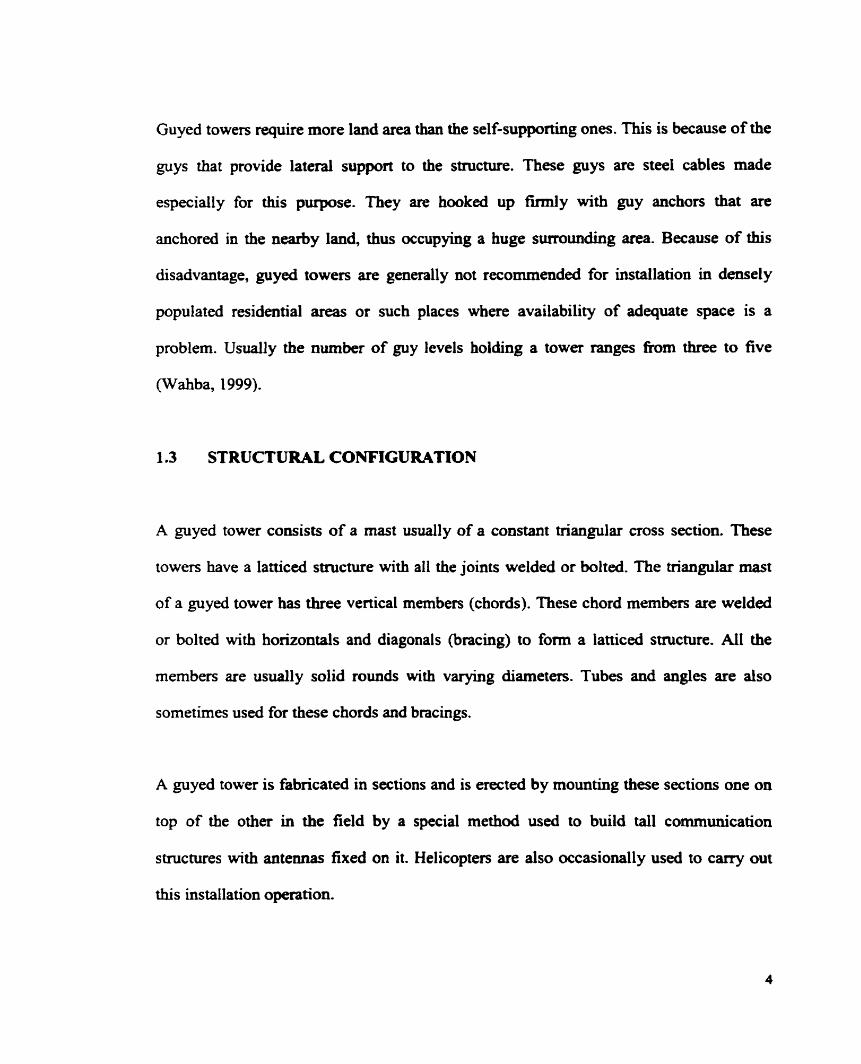
The standard also gives a Nomograph (Figure 2.2) which is based on the assumption that
al1 the columnç in the portion of the fiamework considered reach their individual critical
load simultaneously. This may be used to determine the effective length factors for in-
plane behavior of compression members of tnissa designad as axially loaded members
even though the joints are rigid. In this case, there should be no in-plane eccentricities
and al1 the members of the ûuss meeting at the joint must not reach their ultimate load
simultaneously. Further, the standard says that if it cannot be shown that al1 members at
the joint do not reach their ultimate load simulbneously, then the effective length factor
of the compression members shall be taken as 1 .O.
2.53 AISC-LRFD "LOAD AND RESISTANCE FACTOR DESIGN
SPECIFICATION FOR STRUCTURAL STEEL BUILDINGS"
Chapter E of the LRFD specification deals with columns and other compression-
prismatic members that are subjected to axial compression througb their centroidal axis.
Section E l deal with the Effective Length Factor - K and States that for structural
members under compression it should not be taken as l e s than unity.

End condition code
Figure 2.1 Effective Length Factors for six idealized conditions
(Source: SSRC, 1976)
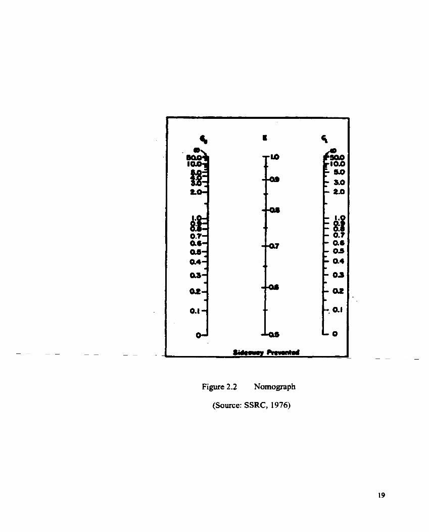
Figure 2.2 Nomograph
(Source: SSRC, 1976)

2.5.4 EUROCODE 3 PART 3.1: 1997 uDESIGN OF STEEL STRUCTURES
TOWERS, MASTS AND t'ilIMNEYS -TOWRS AND MASTS,"
Sub-clause 5.6.2.2 of the code refers to single members and reads as:
"The following rules shouid be used for single angles, tubular sections or solid rounds
where used for chord sections. For chords or chords with axial compression braced
symmetrically in two normal planes, or planes 60' apart in the case of triangular
structures, the slendemess should be detennined from the system length between nodes.
"Where bracing is staggered in two normal planes or planes 60' apart in the case of
triangular stnictures, the system length should be taken as the length between nodes on
one face. For angle sections the radius of gyration about the minor axis should be used to
calculate the slendemess".
Clause 5.7 refers to effective slenderness factor K and States that if the chord members
are solid rounds then the value of K should be taken as 1 .O. This value is for both types of
towers having symmetrical or asymmetrical bracings.
Investigations were carried out on fifieen specimens provided by Electroaics Research,
Inc., Chandler, Indiana, USA, and ten specimens provided by P i r d Inc., Plymouth,
Indiana, USA. The specimens were actual tower segments fabricated by these two
companies. The specirnens provided by ERI hc . were 4.57 m (1 5.0 feet) long while those
provided by Pirod were 6.09 m (20.0 feet) Long. Most of the specimens were
representative samples of acnial tower segments but some were specially fabricated for
these investigations.
3.2 DETAILS OF SPECIMEN
3.2.1 ER1 SPECIMENS:
Fifieen specimens were provided by Electronic Research Institute, Inc. Three different
chord sizes, 69.9, 50.8 and 38.1 mm, were usai with three different diagonal sizes, 15.9,
14.3 and 12.7 mm, respectively. The diagonal bracings were continuous and bent at the
point of welding with the chord memben. Refer to Figure 3.1.
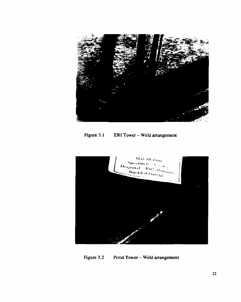
Figure 3.1 ER1 Tower - Weld arrangement
Figure 3.2 Pirod Tower - Weld arrangement

None of the specimens were galvanized. A11 the chord members were made fiom
standard solid rounds with different diameters. The total length of each tower section
provided by ERI hc. was 4.57 m. Each tower section had six panels. AI1 sections were of
triangular cross section with chord, and diagonal mernbers comected together by
welding.
Ten specimens were provided by Pirod Inc. Three different chord sizes, 57.2, 50.8 and
3 8.1 mm, were provided with four different diagonal bracing sizes, 22.2, 1 9.1, 1 5.9 and
22.2 mm. The diagonal bracings were cut and welded to the chord member as s h o w in
Figure 3.2. The total length of each tower section was 6.09 m. Figure 3.3 shows three
Pirod towers section lying in the laboratory. Each section had eight panels. Refer to Table
3.1 for the details of the tower sections.
3.3 TEST SETUP
Al1 the tower specimens were tested in a similar fashion at the Structural Engineering
Laboratory of the University of Windsor. They were first placed in a horizontal position
resting on two roller supports, 1219 mm long and 152.4 mm in diameter. One panel fkom
the bottom chord was chosen for the test and was loaded by the hydraulic jack that was
attached to the loading frame in the laboratory
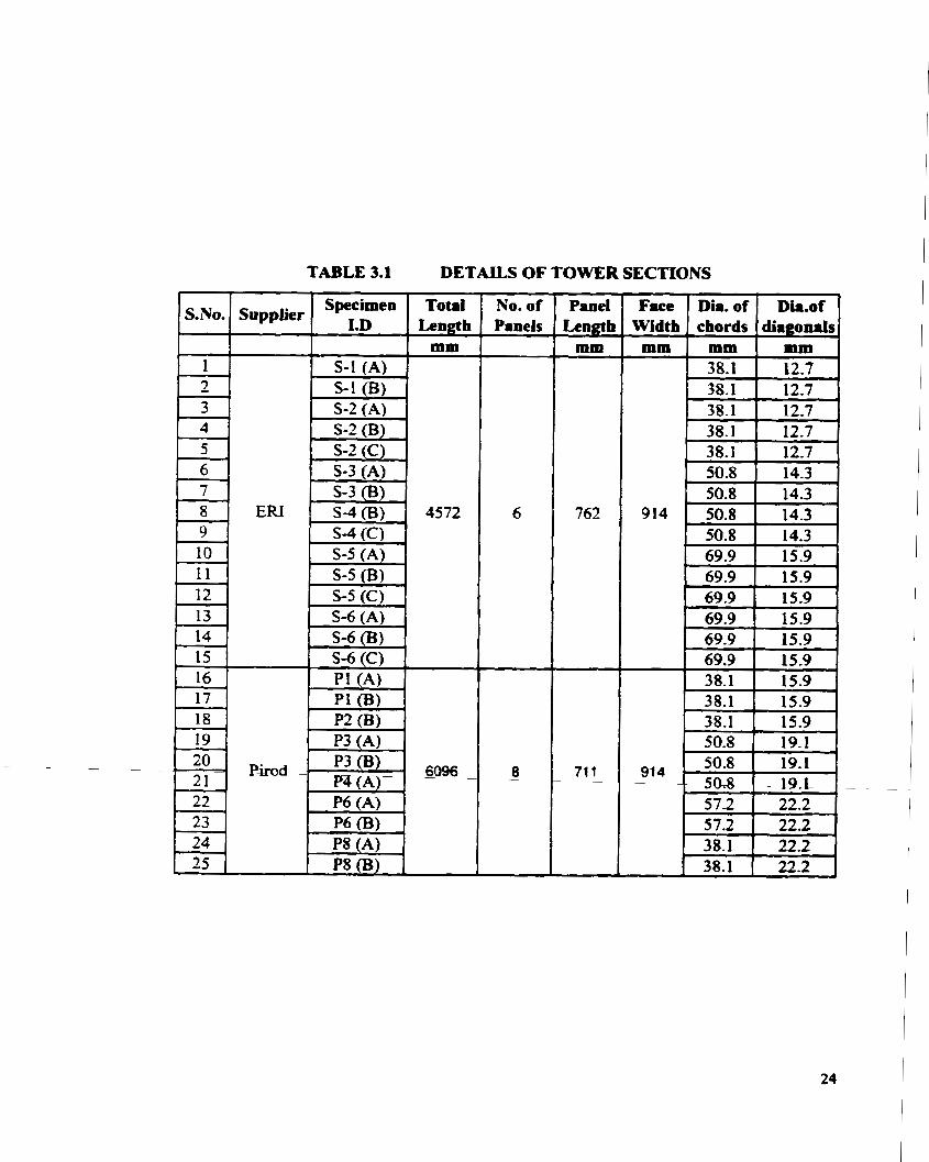
TABLE 3.1 DETAILS OF TOWER SECTIONS
Specimen Total No. of S.NO. Supplier 1.D Lenflb Panels
ERi
S-1 (A) , s-1 (BI
S-2 (A) S-2 (B) S-2 (C) S-3 (A)
, s-3 (B) . S-4 (B)
Panel Lengtb
mm
Face Dia. of Dia.of Width chords diagonds
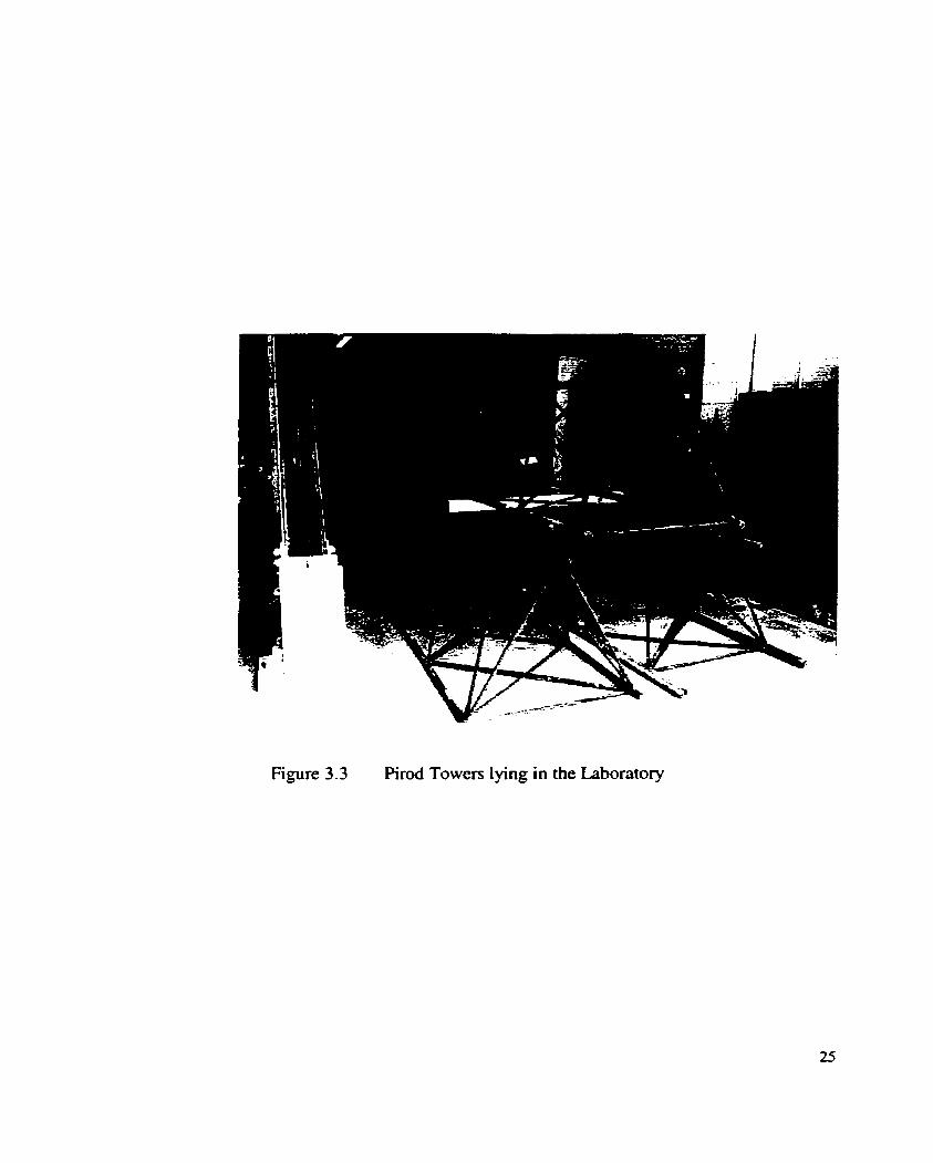
Figure 3.3 Pirod Towers lying in the Laboratory

Figure 3.4 Chord member cut and Ioaded
The chord member was cut beyond its pane1 points/joints on either side of the test section
as shown in Figure 3 -4. The diagonal bracings, however, remained attached :O the chord
member. The cutting was done either with the help of a welding torch or an electric
power saw. The panel, king isolated h m both sides , was then simply supported on
either of its sides on two srnail rollers, 127 mm long and 38.1 mm in diameter. Load was
applied on that panel at the mid-point through a loading block as shown in the test setup
in Figure 3.5
33.1 SUPPORT ASSEMBLY
A support assembly that consisted of several built up steel sections supported the tower at
the ends. These steel sections were assembled together to furnish enough height to be
able to test the specimen ushg the testing fiame available in the laboratory.

Figure 3.5 Test setup

3.3.2 LOAD APPLICATION
The load was applied through a hydraulic jack attached to the testing h e . A 448 kN
(100 kip) load cell was screwed to the bottom of the hydradic jack. An extension was
provided to the load ce11 in the shape of a long solid round cylindrical column, 76.2 mm
in diameter and 1220 mm long. This extension aras needed to fumish the ciifference
between the heights of the load ceil attached to the roof barn and the chord member of
the tower specimen. Refer to Figure 3.6.
The load was applied through loading blocks that were specially machined and grwved
to sit properiy on the chord members having varying diameters. The blocks measured
10 1 - 6 ~ 7 6 . 2 ~ 192.08 mm, 120.65~76.2xi92mm and 139.7~76.2~ 192 mm to sit properly on
the chords having diameters 38.1, 50.8 and 69.9 mm respectively. In between the load
application column and the load block, a ball-and-socket joint, as shown in Figure 3.5,
was introâuced in order to take care of any eccentricity of the applied loading. The load
was applied using a mechanical purnp connected to the hydraulic jack. To measwe the
applied load, a data acquisition system was used which gave readings in kilo-newtons.
3 3 3 DATA ACQUISITION SYSTEM
An automatic &ta acquisition system was used to record the load applied by the
hydraulic jack to the chord member. This was a Datascan 7000 series of Data Acquisition
Modules. A Type 732 1 measurement processor was used that provided directly 8 anaiog

Figure 3.6 Test setup showing the loading column and the support assembly
inputs, including channel excitation and full local channel expansion capability . A type
702 1 analog expansion scanner module was used which provided 8 analog input channels
per scanner, with excitation for transducers. In addition to that, a type 7036 digital
expansion scanner module was used which provided 8 digital input and 8 digital output
channel capability. One arnong the 40 channels was used to know the applied load on the
chord member. The system was hooked up with a 486 DX2 host cornputer (Figure 3.7).
Proper settings were made and the load ce11 was configured to the system before the start
of the actual test.
3.3.4 TESTING OF CHORD MEMBER
A small load was first applied and released to make sure that the whole assembly is
perfectly seated and well placed. In order to measure the deflection due to the applied
loading, a dia1 indicator was fixed exactly below the point where the load was king
applied to the chord member. The indicator was firmly fixed to the adjacent steel section,
which was lying on the floor. No movement was permitteci to enswe undisturbed
readings of the dial indicator once the actual testing procedure was started.
The load was applied in srnaiier incrernents. To make sure that the material does not
yield, the maximum load applied was kept within the elastic range of the chord member.
The maximum load applied varied for each chord depending upon its diameter. For each
load increment, the dia1 gauge reading and the correspondhg applied load were recorded.

Load deflection data were thus obtained for al1 these specimens. Graphs for al1 twenty-
five specimens are given in Appendix A.
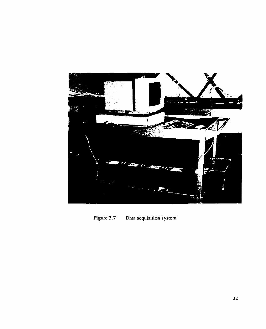
Figure 3.7 Data acquisition system

CEAPTER FOUR
ANALYSIS OF LOAbDEF'LECI'ION DATA
The load deflection data gathered through the experimental procedure were analysed to
determine the effective length factor K. The deflections of the chord member of the tower
were dso compared with the values obtained numerically by using the commercial
software package ABAQUS.
4.2 CALCULATION OF CHORD ROTATION AT TEE ENDS
The deflections, A,, of the chord member of the tower were first calculateci assuming both
ends to be compietely fixed as shown in the Figure 4.1. The downward deflection at mid-
span of the beam, fixed at both ends and loaded with a unifonnly dismbuted load of
length 'c' at its center is given by:
where q is the intensity of loading, 1 is the panel length of the tower, c is the uniforrnly
distrïbuted loaded length, E is Young's modulus of elasticity, 1 is the moment of inertia
a . n d y = c / l .

Figure 4.1 Chord member fixeci at both ends
Equation 4.1 gives the deflection of a beam that is completely fixed on both ends and is
acted upon by a partial u n i f o d y distributed load. This equation was chosen to take into
account the setup in the laboratory where a rectangular block was placed on the chord at
its center (refer to Figure 3.4). It may be aoted that the parameter 'c' in Equation 4.1 is
taken as the width of the rectangular block (76.2 mm) whereas '1' is the panel length
(varying for both types of towers).
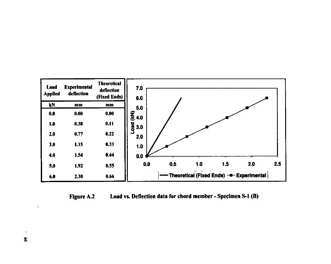
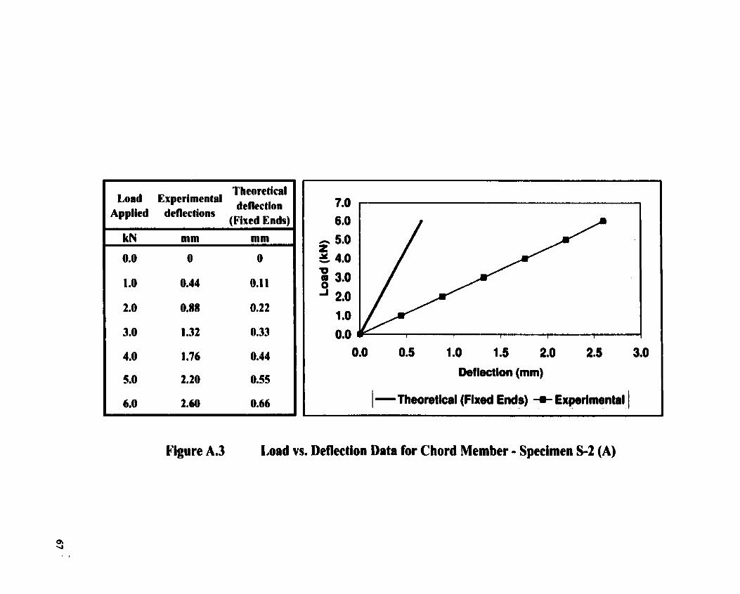
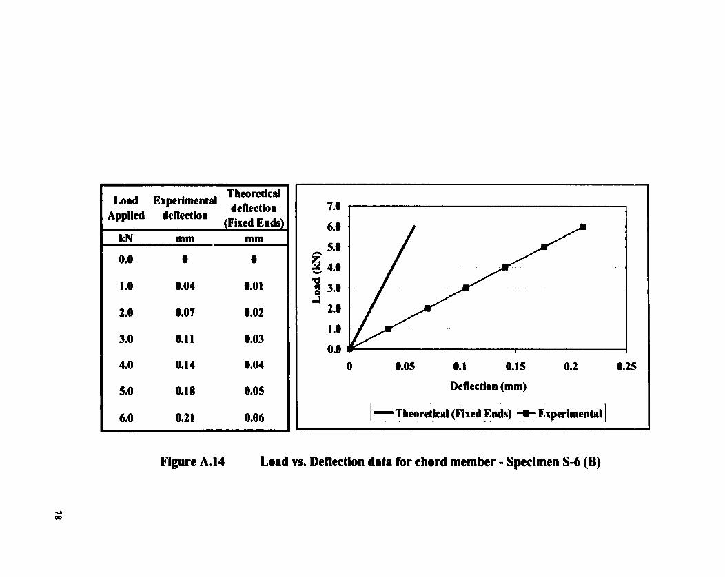
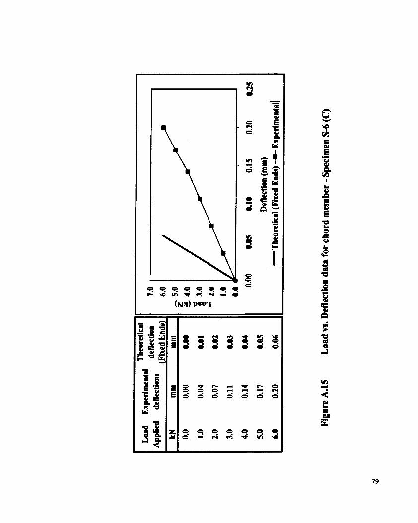
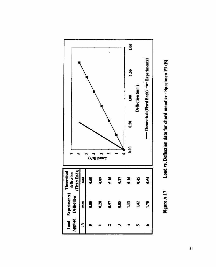
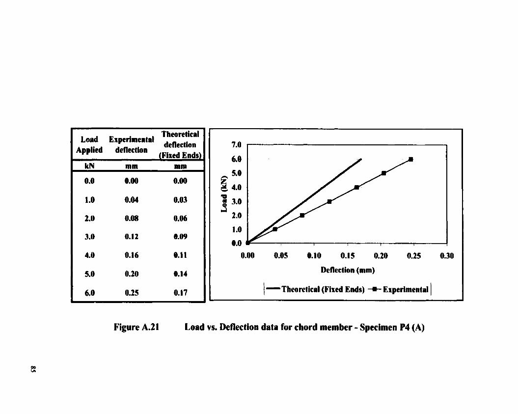
The load versus deflection data was calculated for al1 the towers with the help of
Equation 4.1 . The graphs are ploned b y the side of the experimental deflections and are
given in Appendix A. The difference in the deflection in both the cases is aven by:
AE is the experimental and Ax is the calculated deflection of the chord member. The
clifference occurs because the ends of the beam are not totally restrained in real situation.

For a beam partially restrained at both ends, the siope at each end, 8, is given by:
where, M is the moment at both ends of the chord member. Deflectioq 6, at mid span is
given as:
(4.5)
From Equation 4.4 and 4.5, slope 8, at the ends of the bearn is given by:
where 6 is the differential displacement as calculated in Equation 4.2. The end slope
calculated through Equation 4.6 is given in Table 4.1. Load of 6.0 kN was chosen
arbitrarily for al1 the tower sections provided by both the fabricating companies. At this
load the chord member remained elastic and did not yield.
4 3 CALCULATION OF EFFECTIVE LENGTH FACTOR
Refehg to Figure 4.1, the equation for fixecl-end moment is given as:
The restmiiing moment MR. which is caused by the diagonal bracings at the point of weld
with the chord member is equal to the fïxed end moment less the moment released due to
a rotation 0 of the member. Mathematically, fiom Equations 4.4 and 4.7, MR can be
defined as:
The rotational stiflhess provided by the diagonal bracings to the ends of chord member
cm be caiculated by dividiag the restraining moment with the end slope as given in
Equation 4.9 as:
Rotationai Stifiess - MR 1 9
Equation 4.9 is solved by taking values from Equations 4.6 and 4.8. The results are given
in Table 4.1. The table also gives the value of the restraining moment calculated with
Equation 4.8.

..
S.NO.
1 2 3 4 5 6 7
, 8 9 I O 1 i 12
, 13 14
, 15 16
, 1 7 18
, 19 20
, 21 22
, 2 3 24 25
Specimen ID
S-1 (A) , S-1 (B)
S-2 (A) S-2 (B) S-2 (C) S-3 (A) S-3 (B) S-4 (U) S-4 (C) S-5 (A) S-5 (B) S-5 (C) S-6 (A) S-6 (B) S-6 (C) Pl (A) PI(R) P2 (B) P3 (A) P3 (B) P4 (A) P6(A) P6(B) PB (A) P8 (B)
Dia. of c hord
mm 38.1 38.1 38.1 38.1 38.1 50.8 50.8 50.8 50.8 69.9 69.9 69.9 69.9 69.9 69.9 38.1 38.1 38.1 50.8 50.8 50.8 57.2 57.2 38.1 38.1
STIFFNESS OF
Di ffcrence
mm 1.73Et00 1.64Et00 1.94Et00 1.98Et00 1.97Et00 5.7 1 E-O 1 6.01 E-O 1 5.91 E-01 6.2 1 E-01 1.72E-01 1.67E-O1 1.62E-O 1 1.52E-O I 1.52E-01 1.42E-O 1 1.18Et00 1.16E+00 I.SIE+OO 4.378-0 1 4.228-01 7.608-02 2.9 1 E-O1 2.74E-01 8.1 3E-0 1 7.43E-01
TABLE 4.1
Expt. Deflection (for 6 kN)
mm 2.39 2.30 2.60 2.64 2 -63 0.78 0.8 1 0.80 0.83 0.23 0.23 0.22 0.2 1 0.2 1 0.20 1.72 1.70 2 .O5 0.6 1 0.59 0.25 0.40 0.38 1,35 1.28
ROTATIONAL
Fixed beam def. (for 6 kN)
mm 6.62E-01 6,62E-01 6.628-01 6.628-0 1 6.62E-01 2.09E-O1 2.09E-01 2.09E-01 2.09E-O I 5.84E-02 5.84E-O2 5.84E-02 5 .ME-02 5.84E-02 5.84E-02 5.37E-01 5.37E-01 5.37E-0 1 1.70E-0 1 1.70E-0 1 1.70E-01 1 .ME-0 1 1.06E-01 5,37E-01 5.37E-01
Rot. Sti ffness (Momenl/Slopc)
(Eq. 4.9) N-mrnhdian -
8.50E+06 1.19Et07 ,
1,69E+06 5.6 1 Et05 8.40E+05 1.86Et07 9.08Et06 1.2 1 Et07 3.26Et06 1.73Et07 3.63Et07 5.64E+07 1 .O 1 Et08 1 .O I Et08 ,
1 .SIE+O8 2.17Et07 2.30Et07 4.24Et06 3.2 1 E+07 3.99E+07 1.06Et09 2.91 E+07 4.94Et07 5.80Et07
- 6.89Et07
CHORD
End Slope (Eq. 4.6)
Radians 9.07E-03 8.60E-03 1.02E-02 1 .ME-02 1.03E-02 2.998-03 3.1 SE-03 3.1 OE-03 3.26E-03 9.01 E-O4 8.74E-04 8.488-04 7.96E-04 7.968-04 7.43E-04 6.65E-03 6.548-03 8.51E-03 2.468-03 2.37E-03 4.288-04 1.64E-03 1.54E-03 4.57E-03 4,18E-03
MEMBERS
Resiraining Moment (Eq.4.8) N-mm
7.7 1 Et04 1.03Et05 1,72E+04 5.83Et03 8.68Et03 5.57E+04 2.868+04 3.76E+04 1.06Et04 1 .56E+04 3.1 7E+M 4.79Et04 8.02Et04 8.02Et04 1.1 2E+05 1.44Et05 1.5 1 E+O5 3.61Et04 7.898+04 9.48Et04 4.53EtOS 4.76Et04 7.6 1 Et04 2.658+05 2.88Et05
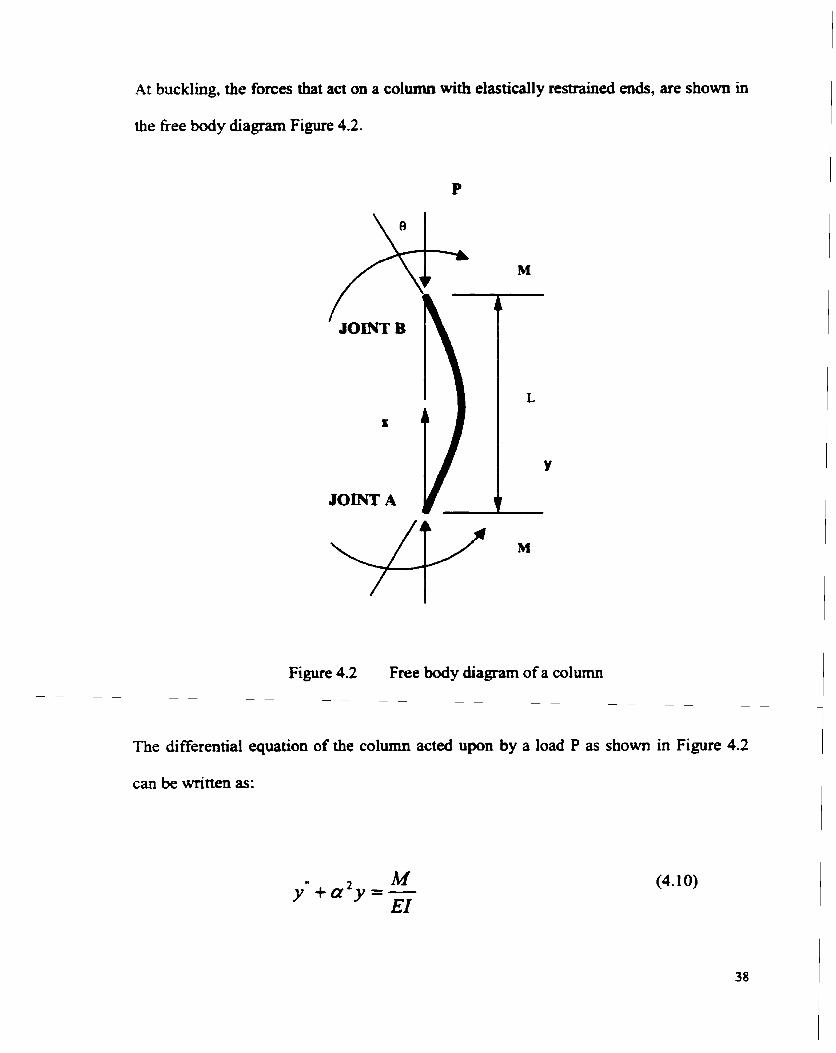
At buckling, the forces that act on a column Mth elasticall y restrained ends, are shown in
the fiee body diagram Figure 4.2.
Figure 4.2 Free body diagram of a column - - - - - - - - - - - -
- - - - -
The differential equation of the column acted upon by a load P as shown in Figure 4.2
can be written as:
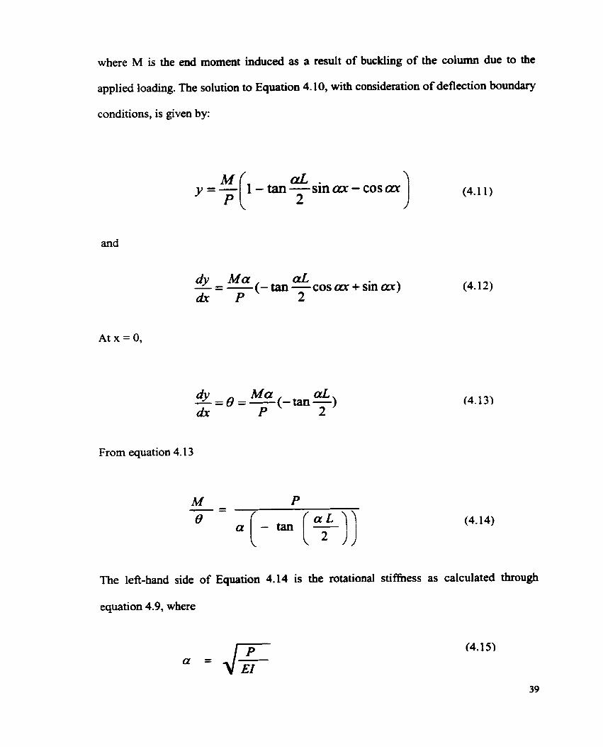
where M is the end moment induced as a result of buckling of the column due to the
applied loading. The solution to Equation 4.10, with consideration of deflection boundary
conditions, is given by:
and
dy M a aL - = -(-tan -cosax+ sin ax) dx P 2
From equation 4.13
The lefbhand side of Equation 4.14 is the rotational stiffhess as calculated through
equation 4.9, where

Euler's equation for elastic buckling of columns is given as:
Equations 4.14 was solved for P, which was substituted subsequently in Equation 4.16 to
find out the effective length factor, K. Young's rnodulus of elasticity was taken as
200 000 MPa while ï, the moment of inertia, and 1, the panel length, varied depending on
the type of tower under consideration- The values of the effective length factor
(Experirnental) so obtained are given in Table 4.2.
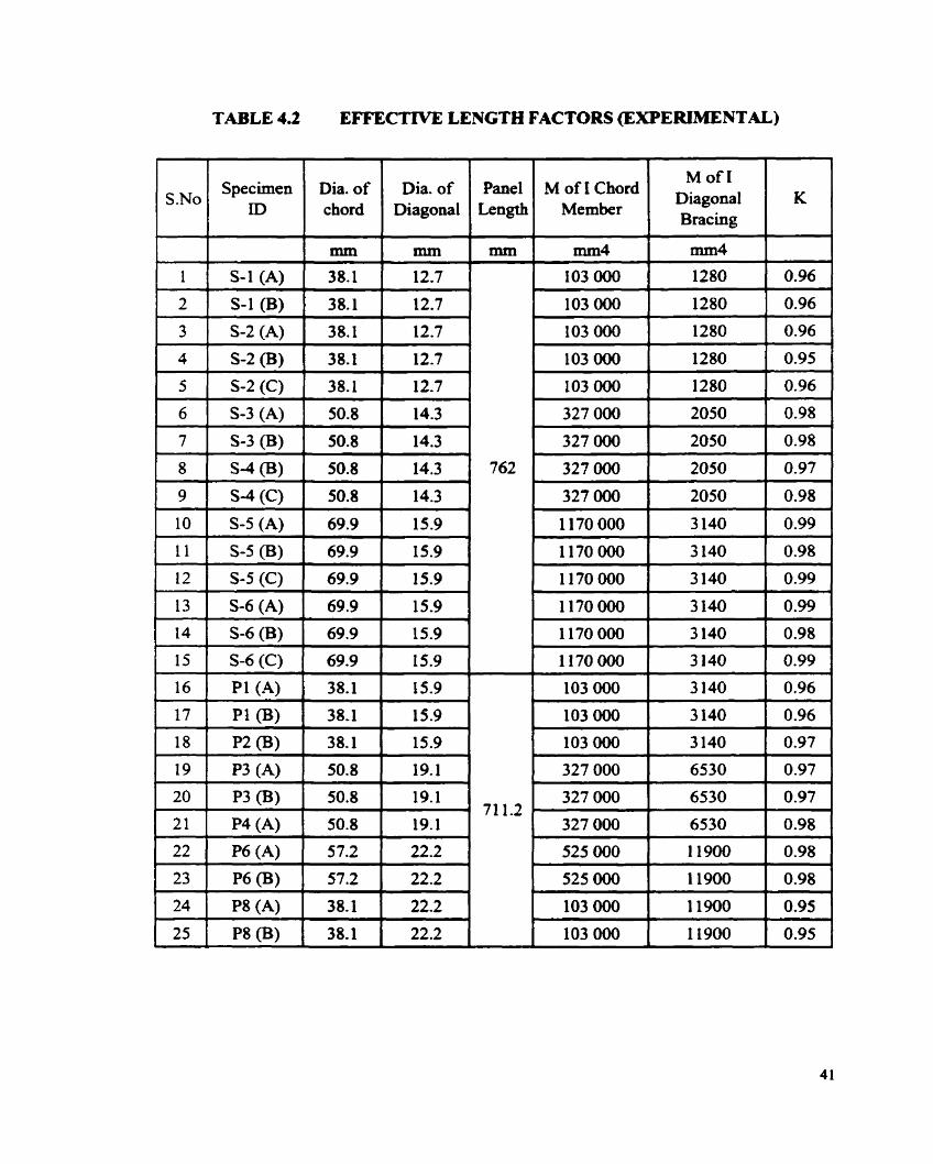
TABLE 4.2 EFFECTIVE LENGTH FACTORS (EXPERIMENTAL)
1 1 S-1 (A) 1 38.1 1 12.7 1
S.No
3 1 S-2 (A) 1 38.1 1 12.7 1
6 1 S-3 (A) 1 50.8 1 14.3 1
Specirnen ID
7 1 S-3 (B) 1 50.8 1 14.3 1
9 1 S-4 (C) 1 50.8 1 14.3 1
Dia. of chord
mm
1 1 1 S-5 (B) 1 69.9 1 15.9 1 12 1 S-5 (C) 1 69.9 1 15.9 1
Dia. of Diagonal
mm
15 ( S-6 (C) 1 69.9 1 15.9 1
Panel Length
mm
13
14
M of 1 Chord Member
mm4
S-6(A)
S-6 (B)
16
17
18
19
20
21
22
23
24
25
MofI Diagonal Bracing
mm4
69.9
69.9
K
15.9
15.9
Pl(A)
pl (BI
p2 (BI
p3 (A)
p3 (BI
P4 (A)
P6 (A)
p6 (B)
P8 (A)
p8 (BI
103 000
103 000
103 000
327 O00
327 000
327 O00
525 000
525 000
103 000 1
IO3 000
3 140
3 140
3140
6530
6530
6530
11900
1 1900
11900
1 1900
71 1.2
. 38.1 1 15.9
3
0.96 I
0.96
0.97
0.97
0.97
0.98
0.98
0.98
0.95 I
0.95
38- 1
38.1
50.8
50.8
50.8
57.2
57.2
38.1
38.1
A
15.9
15.9
19.1
19.1
19.1 1
22.2 1
22.2
22.2
22.2
4.4 COMPARISON OF DEFLECTIONS WITH ABAQUS RESULTS
Numerical investigation was carried out with the commerciai cornputer software package
ABAQUS in order to compare theoretical results with the deflections of the chord
members obtained experimentally. A model of a typicai six-panel tower section, ERI
specirnen, was generated with 40 nodes as s h o w in the Figure 4.3. The boundary
conditions were defined in the same manner as the tower was placed in the laboratory for
testing.
The eiement library in ABAQUS contains several types of beam elements. Different
beam elements in ABAQUS use different assumptions. The beam elements chosen for
the model definition of the tower are the Timoshenko (shear flexible) beams. These
bearns allow for transverse shear deformation. They are used since they provide usefil
results for such beams that are made fiom unifom material. ABAQUS assumes that the
transverse shear behaviour of Timoshenko bearns is linear elastic with a fked modulus
and, thus, independent of the response of the beam sections to axial stretch and bending.
Refer to Appendix B for INPUT FlLES FOR ABAQUS.
It may be noted that in the model, Figure 4.3, with reference to the chord member on
which the load is applied the adjacent chord mernbers are not provided. This is to
resemble the situation in the laboratory whereby the chord member was cut beyond the
panel junction. In order to apply a central concentrated load at the middle of the chord
member an extra node was defined at that point.
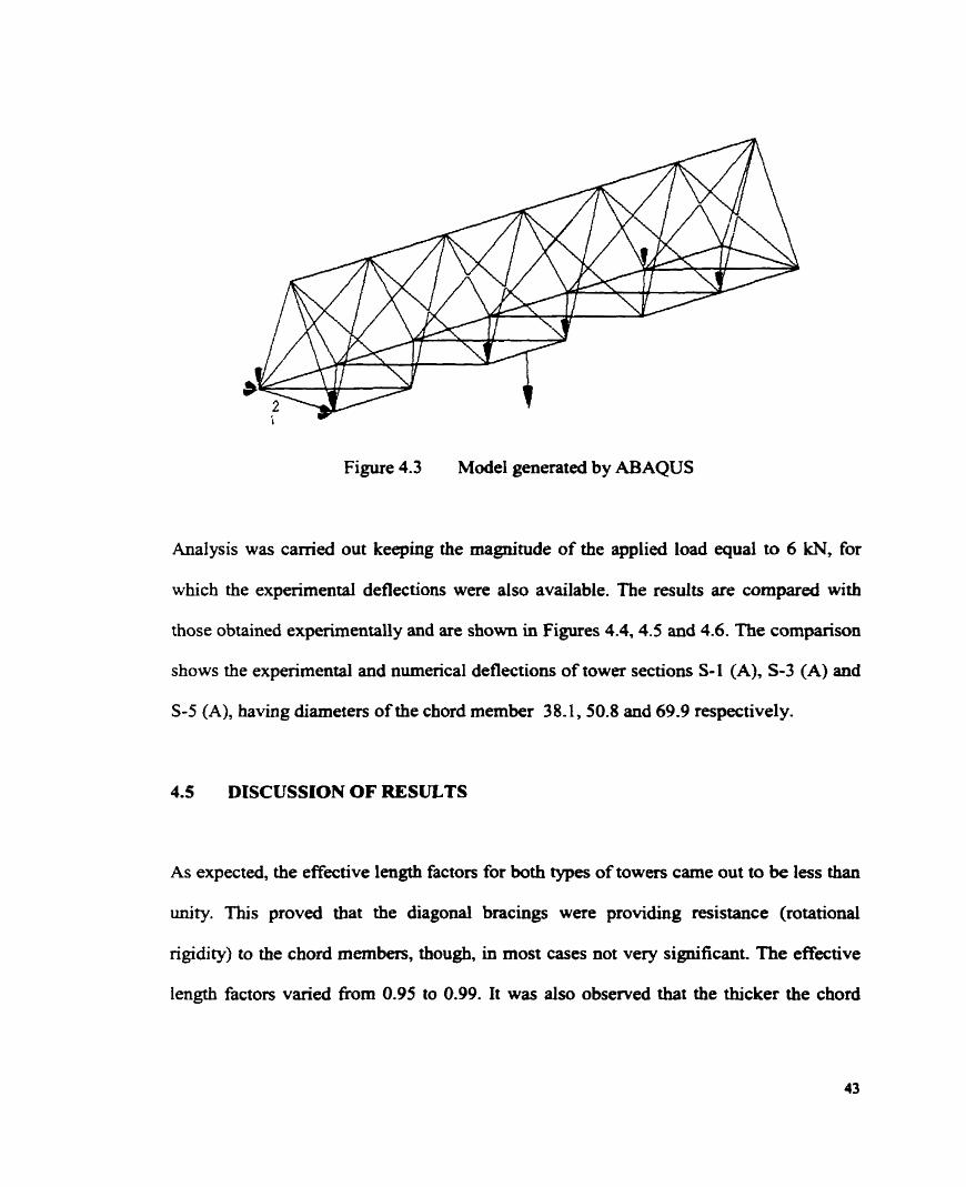
Figure 4.3 Mode1 generated by ABAQUS
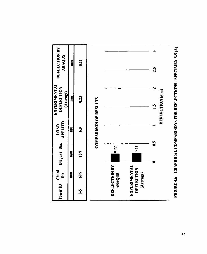
Analysis was camed out keeping the magnitude of the applied load qua1 to 6 kN, for
which the experimental deflections were also availabie. The results are compared with
those obtained experimenîally and are shown in Figures 4.4.4.5 and 4.6. The cornparison
shows the experimental and numencal deflections of tower sections S-1 (A), S-3 (A) and
S-5 (A), having diameters of the chord member 38.1,50.8 and 69.9 respectively.
4.5 DISCUSSION OF RESULTS
As expected, the effective length factors for both types of towers came out to be less than
unity. This proved that the diagonal bracings were providing resistance (rotationai
rigidity) to the chord memben, though, in most cases not very significant. The effective
length factors varied from 0.95 to 0.99. It was also observed that the thicker the chord
member the more closer the effective length factor was to unity. The difference in the
weid arrangement of two towen did not have a significant effect on the resuits. Thus, it
can aiso be said that the diagonals do not provide significant rotational resnaint to the
chord member, though they do provide lateral restraint. The results obtained through
commercial software package ABAQUS gave deflections that were a little less than the
experimental ones. This may be due to the reason that the mode1 generated in the
cornputer was stiffer than the one tested experimentally and had ideal loading and
supporting conditions. The error between the numerical and experimental results was
observed to be less than 5%.
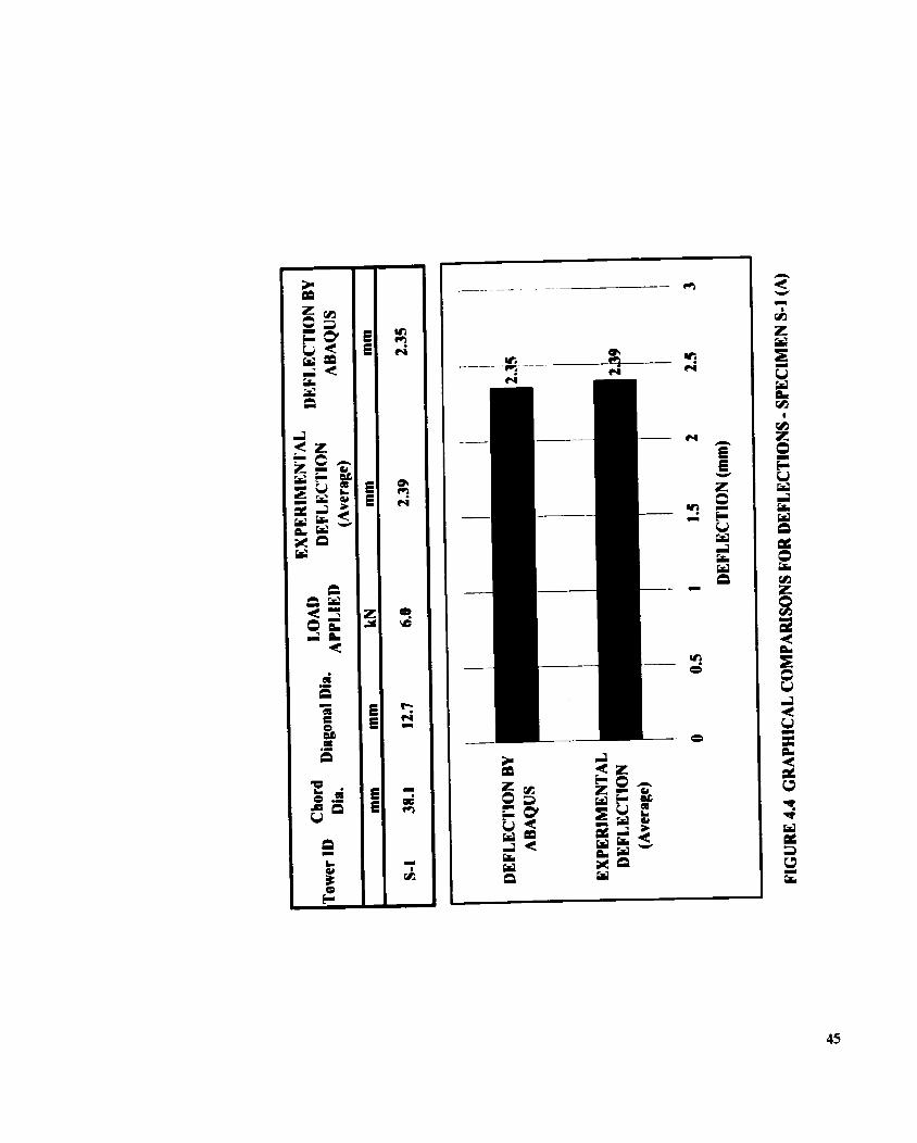

Chord Diagonal Dia.
LOAD Tower ID
DEFLECTION BY APPLIED
DEFLECTION (Average)
ABAQUS
mm mm kN mm mm
COMPARISON OF RESULTS
DEFLECTION BY ABAQUS
EXPERIMENTAL DEFLECTION
(Average)
DEFLECTION (mm)
FIGURE 4.5 CRAPHICAL COMPARISONS FOR DEFLECTIONS - SPECIMEN S-3 (A)

C H A P ' r E R r n
AIYALYTICAL INVESTIGATION
The effective length factors of the chord members of guyed towers were also calculated
analytically using the equation of equilibrium. The relative stifiess ratio, the G-factor,
was calculated using the structural anal ysis cornputer s o h a r e STAAD/Pro.
5.2 EQUILIBRIUM EQUATION
Ln this case the chord member of the tower, which was attached with diagonal bracings,
is considered a case similar to an axially loaded coiumn in a h e d structure. Where
continuous construction is used, the beam-to-column connections are rigid. In this
situation, the column-end rotation, that take place during the bending motion of the
column will induce corresponding rotations in the &am-ends. Bending moments will be
developed at the connections, and these will restrain the motion of the column and
ttiereby increase its strength.
To understand the analpis procedure, the buckling strength of a column in a typical
frame is considered as shown in the Figure 5.1. Buckling would occur on the application

of an axial force. During the buckling motion, the ends of the columns rotate th rougi^
angles Ou (Figure 5.2).
Ln order to consider the buckling strength of the column IJL, the portion of the fiame has
been isolated in Figure 5.2. The dotted line shows the position of the frame before load is
being applied to it. At buckling the additional deformation of the column and adjacent
members are also shown in the Figure. Assurnhg that during the buckling motion, the
ends of columns rotate through an angle 8~ or 8 ~ ; the barn ends are forced through this
same amount of rotation. A resisting moment, MU=, will be created at the beam-to-
column connection given by the following equation:
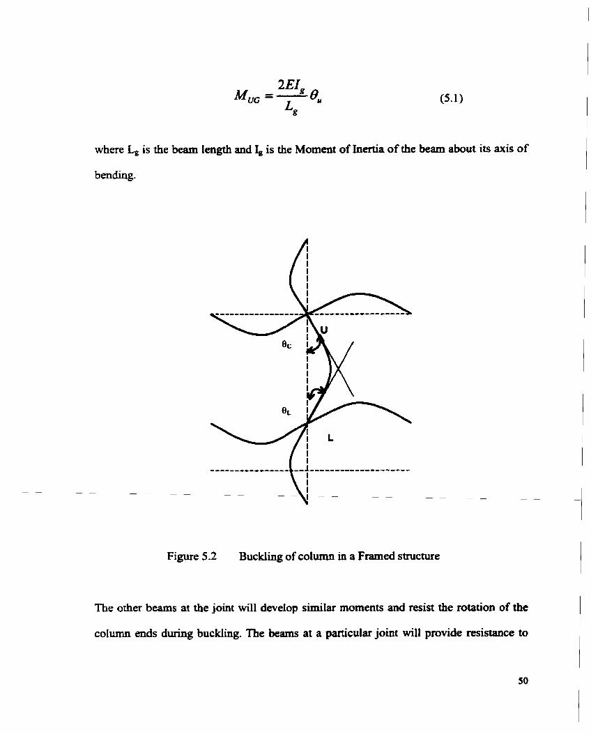
where L, is the beam length and 1, is the Moment of Inertia of the beam about its axis of
bending.
Figure 5.2 Buckiing of column in a Framed structure
The other beams at the joint will develop similar moments and mist the rotation of the
column ends during buckling. The beams at a paiticular joint will provide mistance to
columns both above and below that joint. Assuming the mistance to buckling is in
proportion to the stifniess, ï&, of the column considered, the net resisting moment, Mu,
acting on the column will be given by:
The symbol I: indicates a summation for al1 memben rigidly ~ 0 ~ e C t e d to the joint and
lying in the plane in which buckling is king considered. is the column moment of
inertia and L, is the length of the column (Kulak, Adams and Gilmor, 1985).
5.3 DETERMINATION OF ROTATIONAL STWFNESS USING STAAD/Pro
The differential equation of equilibriurn is no longer that for a pin ended column, but
must account for the presence of the end moments and shears. The solution to the
differential equation can be expressed by the following equation given by the structural
stability research council (SSRC, 1976).

where Gc and Gi. are defined in equation 5.4 for joints U and L. respectively. K is the
effective length factor of the colurnn under consideration and is defined as the ratio of the
effective iength to the actual length. Equation 5.4 has been plotted as a Nomopph. as
shown previously in Figure 2.2. The chord member of the tower. having similar
conditions at both ends reduces Equation 5.4 into Equation 5.5:
The value of relative stiffness ration. G. was deterrnined analytically by using the
structural analysis software STAADPro. The rnodel of the whole tower was generated
using the modellinp facility given in STAADIPro. which is an interactive menu-dnven
graphics oriented procedure for creating a rnodel. The model had 39 nodes. (Refer to
Figure 5.3). The value of E was taken as 100 000 MPa and Poisson's ratio as 0.3.
Figure 5 -3 Tower model generated using STAADPro

The dimensions of the chord members (panel length and diameter) were changed for
different tower specimens as they varïed for both the fabricating companies.
Figure 5.4 Section of tower taken out for analysis
One joint region of the tower, which included two chord members with four diagonal
bracings attached to it. as shown highlighted in Figure 5.1. was taken out for analysis.
This was to find out the rotationai stiffness of the chord member for use in the
equilibrium Equation 5.5.
1''
Figure 5.5 Moment applied on tower joint
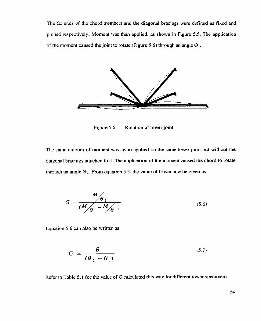
The far ends of the chord mernbers and the diagonal bncings were defined as fixed and
pinned respectively. Moment was than applied. as shown in Figure 5.5. The application
of the moment caused the joint to rotate (Figure 5.6) through an angle 01.
Figure 5.6 Rotation of tower joint
The same amount of moment was again applied on the sarne tower joint but without the
diagonal bncings attached to it. The application of the moment caused the chord to rotate
through an angle 0 7 . From equation 5.3, the value of G can now be given as:
Equation 5.6 can also be written as:
Refer to Table 5.1 for the value of G cdcdated this way for different tower specimens.
54

Table 5.1 VALUE OF G CALCULATED USINC STAADPro
Specimen Chord Panel Diagonal SfAAD/Pro S.No
G / 1 ID 1 Dia 1 Length 1 Dia 1
4 S-2 (B) 38.1 762 12.7 4.553 4.62 1 66.6 5 S-2(C) 38.1 762 12.7 4.553 4.62 1 66.6 6 S-3 (A) 50.8 762 14.3 1.449 1.466 86.0 7 S-3 (B) 50.8 762 14.3 1.449 1 A66 86.0 8 S-4 (B) 50.8 762 14.3 1 -449 1 -466 86.0
1
2
10 S-5 (A) 69.85 762 15.9 0.41 0 0.4 13 147.4
11 S-5 (B) 69.85 762 15.9 0.4 10 0.4 13 147.4
S-l(A) S-1 (B)
13
14
15 16 17 18
mm 38.1 38. t
21
22 23 24 25
S-6 (A) S-6 (B) S-6 (C)
Pl(A) Pl@) P2 (B)
mm 762 762
P4 (A) P6 (A) P6 (B)
PS(A) P8@)
69.85 69.85
69.85
38.1 38.1 38.1
mm 12.7 12.7
50.8 57.15 57.15 38.1 38.1
762 762
762 71 1.2 71 1.2 71 1.2
71 1.2 71 1.2 71 1.2 711.2 71 1.2
66.6 66.6
06 MEMBERS radians 4.553 4.553
15.9 15.9 15.9 15.9 15.9 15.9
02 MEMBERS radians 4.62 1 4.62 1
19-05 22.225 22.225 22.225 22.225
0.4 1 O 0.410 0.410 4.133 4.133 4.133
1.331 0.829 0.829 3.690 3.690
0.4 13 0.4 13 0.413 4.600 4.600 4-60
147.4 147.4 147.4 8.8 8.8 8.8
1.460 0.9 13 0.9 13 4.600 4.600
10.3
9.9 9.9 4.1 4.1

5.4 CALCULATION OF EFFECTIVE LENGTH FACTOR
By substituthg the vaiue of G in Equation 5.5 the effective length factor of the chord
member was calculated. Equation 5.5 was solved such that the sum of al1 the values on
the left-hand side equals to unity. Solver option of the Microsoft Excel package was used
for t h i s purpose.
Microsoft Excel Solver uses the Generalized Reduced Gradient. With Solver, an optimal
value for a formula in one cell, called the target cell on a worksheet, was calculated.
Solver worked with a group of cells that were relate. either directly or indirectly, to the
formula in the target cell. Solver adjusted the values in the changing cells which were
specified. called the adjustable cells, to produce the resuit which were specified from the
target ce11 foxmula. Constraints were applied to restrict the values solver can use in the
model. Refer to Table 5.2 for the values of K calculated through this method.
5.5 DISCUSSION OF RESULTS
The effective length factors found through this procedure matched with the resuits
obtained through the analysis of the load deflection data and varied fkom 0.93 to 0.99.
The rotational stifbess values of chord and diagonal members were calculated fiom the
structural analysis cornputer soffware STAADRro. The relative stifnless factor, G, varied
h m 147 to 4. The effective length factors so determinecl were found to be in accordance
with the Nomograph provided in CANKSA S 16.1, which is based on the G factor.
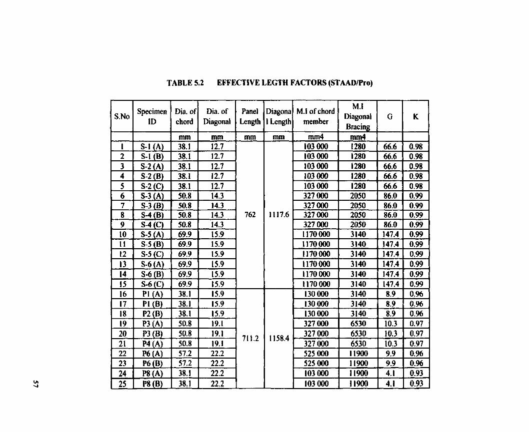
TABLE 5.2 EFFECTIVE LEGTH FACTORS (STAADIPro)
Y
- - "i
- II-
-" I i
I - - - 4-
- - -
I I
- I
.c. - I I
I I
I - -. W C
-.
-"
-. -. W .
m.
-
Diagona M.1 of chord Diagonal M ' 1 g ! 6
I Length member Bracin
Specimen Dia. of Dia. of ID 1 chord 1 Diagonal
Panel Length
S-3 (A) 1 50.8 1 14.3 S-3 (B) 50.8 14.3 S-4 (B) 50.8 14.3 S-4 (C) 50.8 14.3 S-5 (A) 69.9 15.9 S-5 (B) 69.9 15.9 S-S(C) 69.9 15.9 S-6 (A) 69.9 15.9
Pi (A) 1 38.1 1 15.9 1
P8 (B) 1 38.1 1 22.2 1

CHAPTER SIX
CONCLUSIONS AND RECOMMENDATION
Chord members of twenty-five specimens, actuai tower sections provided by two
companies, were tested by applying a load at the center. Al1 the tower sections had a
triangular cross section and were made up of solid rounds. The joints were welded and
none of the tower sections was galvanized. The data gathered through experiments was
used to find out the effkctive length factors. Effective length factors were also calculated
by using the equilibrium equation.
6.2 CONCLUSIONS
Based on the analyticai and numencai analysis, the following conclusions can be drawn:
1. The effective length factor of the tower sections calculated through the analysis of
the experimental data, was found out to be less than unity. The value ranges fiom
0.95 to 0.99. Thus it was determined that the rotational restraint provided by
diagonal bracing to the chord member is not very significant, specially for the
case where a relatively thicker chord member is fabricated wiîh a relatively
thimer diagonal bracing.

2. The values of the effative length factors obtained by making use of the
equilibrium equation given by structural stability research council (SSRC, 1976)
were found to be close to the values obtained through the analysis of the load
deflection data. Thus, the equilibrium equation or more conveniently the
Nomograph (Figure 2.2), c m be used to detennine the efiective length factor of
chord membem of guyed towers.
3. Good agreement was observai betweetl the results obtained through commercial
software package ABAQUS and the experimental data.
Since the effective length factors were found to be very close to 1 .O so it is recommended
that the effective length factor for solid round chord members of guyed towers should be
taken as unity as recomrnended by Canadian Standards Association S37-94
"ANTENNAS, TOWERS, AND ANTENNA-SUPPORTING STRUCTURES".

REFERENCES
ABAQUS, 1998, Version 5.8, Hibbitt, Karlsson & Sorenson, Inc. RI, USA.
American Institute of Steel Construction, 1993, "Load and Resistant Factor Design
Specificstion for Structurai Steel Building," American Institute for Steel Construction,
Chicago, IL, November.
Amencan Society of Civil Engineers, 1998, "Design of Latticed Steel Transmission
Structures".
Aydm, R. and Gonen, H., 1994, "Lateral Stinnes of Frames and Effcetive Length of
Framed Columns," J o u d of Structural Engineering, ASCE, Vol. 120, No. 5, May, pp.
1455- 1470.
Bridge, R.Q. and Fraser, D.J., 1987, 'Improveà GFactor Method For Evaluating
Effective Lengths of Columns," Journal of Structural Engineering, ASCE, Vol. 1 13,
No. 6, June, pp. 1341-1356.
Canadian Standards Association, 1994, "Antennas, Towers, and Antenna-Supporting
Structures," CSA S37-94, Etobicoke, Ontario.
Canadian Standards Association, 1994, "LMt States Design of Steel Structures,"
CANICSA-S 16.1-M94, Etobicoke, Ontario.

CEN, 1997, Eurocode 3 Part 3.1: 1997, "Design of steel structures Towers, masts and
C himneys - Towers and Masts", CEN, European Cornmittee for Standardisation,
Brussels, Belgium.
Chen, W.F., 1987, "Structural Stability Tbeory and Implementation," Elsevier
Science Publishing Co., Inc., New York.
Cheong-Siat-Moy, F., 1997, 'K-fpctors for braced hmes," Engineering Stnictures,
No. 9, Elsevier Science Ltd, pp. 760-763.
Duan, L. and Chen, W., 1988, '<Effective Length Factor for Columis in Braced
Frames," Journal of Stnicnual Engineering, ASCE, Vo1.114, No.10, October, pp. 2357-
2370.
Duan, L. and Chen, W., 1989, Tffcctive length Factor for Columns in Unbraced
Frames," Journal of Structural Engineering, ASCE, Vol. 115, No. 1 , January, pp. 149-
165.
Fraser, D.J., 1983, uEvaiuation of effective lengtb factors in braced frimes,"
Canadian Joumal of Civil Engineering, 10, pp. 1 8-26.
Galarnbos, T.V., 1998, 'CGuide to Stabüity Design Criteria for Metal Structums,~
Fourth Edition, John Wiley & Sons, Inc.
Hajar, J. F. and White, D.W., 1995, uEffktïve Length and Equivalent Imperfection
Approaches for Assessing Frime Stabiiity," Restnicniring: America and Beyond;
Proceedings of Structures Congres XIII held in Boston, Massachusetts, April, pp. 1785-
1788.
Hellesland, J. and Bjorhovde, R, 1996% YImproved Frime Stability Analysis with
Effective Lengths," Journal of Structural Engineering, ASCE, Vol. 1 22, No. 1 1,
November, pp. 1275-1 283.
Hellesland, J. and Bjorhovde, R., 1996b, "Ratraint Demand Factoton and Effective
Lengths of Bnceà Columns," Journal of Strucîurai Engineering, ASCE, Vo1.122,
No.10, October, pp. 121601224.
Indian Standard code of Practice, 1.S 802-1978, Part 3 testing, Governent of India, New
Dehli, India.
Kishi, N., Chen, W.F., Goto, Y., 1997, "Effective Length Factor of Columns in
Semirigid and Unbraced Frimes," Joumal of Smcturai Engineering, ASCE, Vo1.123,
No.3, pp. 3 13-320.
Kishi, N., Goto, Y., Komuro, M., 1995, "Effective Length Factor for Columns in
Braced and Flexibly Jointed Frames," Engineering Mechanics: Proceedings of the IO&
Conference, University of Colorado at Boulder, Boulder, Colorado, May.
Knight, G.M.S. and Santhakumar, A-R, 1993, "Joint effects on behavior of
transmission towers," Journal of Smcîurai Engineering, ASCE, Vol. 11 9, No.3, March,
pp. 668- 712.
Kulak, Adams and Gilmor, 1985, "Limit States Design in Stmcturai Steel," Canadian
Institute of Steel Constniction.
SSRC, 1976, Stnicniral Stability Research Council 'GiMe to sîabiiity criterion for
metal structures", 3d Edition, John Wiley & Sons, NewYork, USA.
STAAD/Pro, 1997-1998, Release 3.0, Research Engineers, Research Engineers Corp.
Headquarters, CA, USA
Wahba, Y.M.F., 1999, "Static and Dynamic Analyses of Guyed Antenna Towers,"
Ph.D. Thesis, University of Windsor, Windsor, Ontario, Canada.
White, D.W. and Hajjar, J.F., 1997, 'Design of steel trames without consideration of
ef'fective length," Engineering Structures, Vol. 19, No. 1 O, pp. 797-8 10.
Wood, R.H., 1974, 'Effective Lengtb of columns in multi-story buiidings," The
S tmctural Engineer, Volume 5 2, No.7, Jul y.

APPENDIX - A FIGURES
I Theoretical Lord Experimental deflec,ion
Applicd de fiect ion (Fixed Ends)
1 -Theoretlcal (Fixeâ Ends) + Experimental 1
Figure A.2 Load vs. Deflection data for chord member - Specimen S I (B)
Thcaretical Load Experimental
deflec tion Applied deflections
(Fixed Ends)
0.0 0.5 1 .O 1.5 2.0 2.5 3.0
Deflectlon (mm)
1 - ~heoretlcal (Fixd Ends) +- Experlmental 1
Figure A.3 Load vs. Deflection Data for Chord Member - Speeimen S-2 (A)


I Theoretical Load Experimentrl
Applied defiedion deiiection
(Fired Ends) 6.0
5 4 4.0 P 8 3.0 cil
2.0
1 .O
o e o
0.00 0.50 1 .O0 1 .!!O 2.00 2.50 3.00
Deflection (mm)
1 - ~hearetkil (Flxed Ends) -O- Esperîrnentd 1
Figure A.5 Load vs. Deflection data for chord member - Specimen 5-2 (C)
T heoreîical Load Experimental
deflection A~~lied denedion (Fixed Ends)
0.00 0.20 0.40 0.60 0.80 1 .O0
Dofîection (mm)
1-~heoretical (Fixcd Ends) + Experirnental /
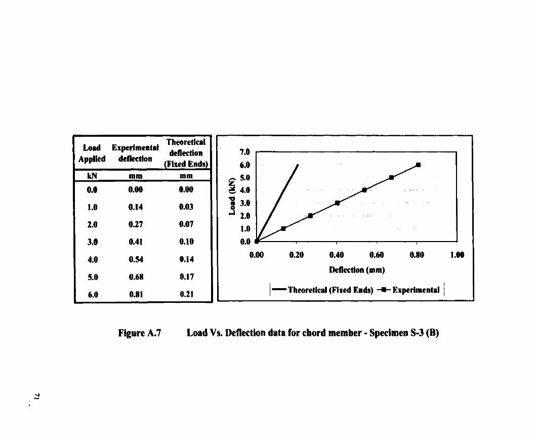
Figure A.7 Load Vs. Deflection data for chord member - Specimen S-3 (B)

O 0.05 0. 1 0.15 0.2 0.25
Deflection (mm)
1 -~heoreticil (Fixcd Ends) -+ Expcrimcntil 1
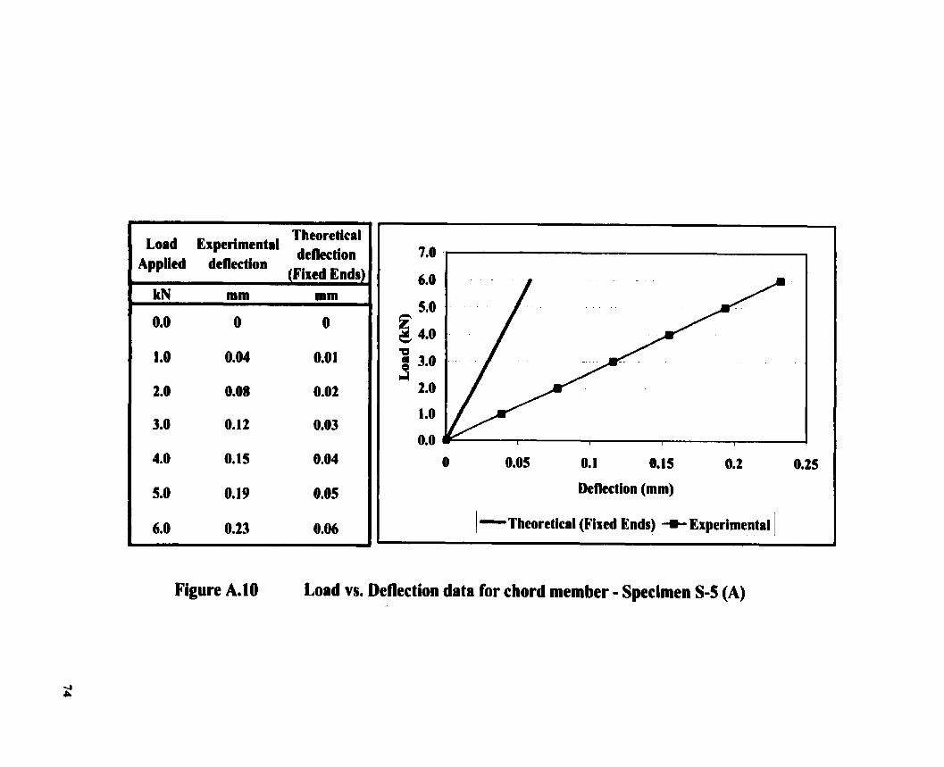
Figure A.10 Load vs. Deflection data for chord member - Specimen S-5 (A)

Load Experimental Theoretical
Applied deflection deflection IFixed Ends)
O 0.05 0. 1 0.15 0.2 0.2s
Deflect ion (mm)
Figure A.1 I Load vs. Deflection data for chord member - Specimen S5 (B)
Load Experimental T heoretical
Applied deflection deflection (Fixed End81
0.05 0.10 0.15 0.20
Deflecîion (mm)
1 - ~heoretiral (Fixcd Ends) + Experimcntrl
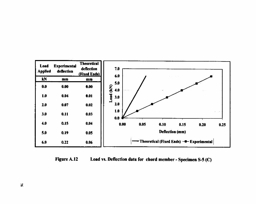
Figure A.12 Load vs. Deflection data for chord member - Specimen S-5 (C)

Theoretical Load Experimental deflectioi
0.00 0.05 0.10 0.15 0.20 0.2s
Denection (mm)
Figure A.13 Load vs. Deflection data for chord member - Specimen S-6 (A)
I Theoretical Load Experimental
deflection Applied deflection
(Fixed Endsl
O 0.05 0. 1 0.15 0.2
Deflection (mm) I 1 -~heoretical (Fixed Ends) + Experimcntrl 1
Figure A.14 Load vs. Deflection data for chord member - Specimen S-6 (B)

I Theoretical Load Enpetimental
deiiection Applied deflection (Fined Ends)
0.00 0.50 1 .O0 1.50 2.00
Deflcction (mm)
1-~hearcticd (Fired Ends) +- Enperimentil 1
Figure A. 16 Load vs. Deflectlon data for chord member - Specimen P I (A)

I Theoretical Load Expcrimental
Applied deflection lFixed Ends)
0.00 0.50 1 .O0 1 .SO 2.00 2.50
Deflection (mm)
1 - ~heoreticiil (Fixcd Ends) + Experimeitd )
Figure A.18 Load vs. Deflection data for chord member - Specimen P2 (B)


I Theoretical Load Experimental
defiection A~~lied denec''' { Piscd Ends)
0.00 0.05 0.10 O. 15 0.20 0.25 0.30
Defiec t ion (mm)
1 -theoretical (Fixcd Ends) +- Experimcntal 1
Figure A.21 Load vs. Deflection data for chord member - Specimen P4 (A)

Theoretical Load Ex perimental deflection
AppUed deflection
0.00 0.10 0.20 0.30 0.40
1-~heoretiral (Fixed Ends) + Experimental 1
Figure A.23 Load Vs. Deflection data for chord member - Specimen P6 (B)
Theoretical Load Experimental
deflection
0.50 1.00 1 -50
Deflection (mm)
1 - ~hcaretiçal (Fired Ends) + Experimental\
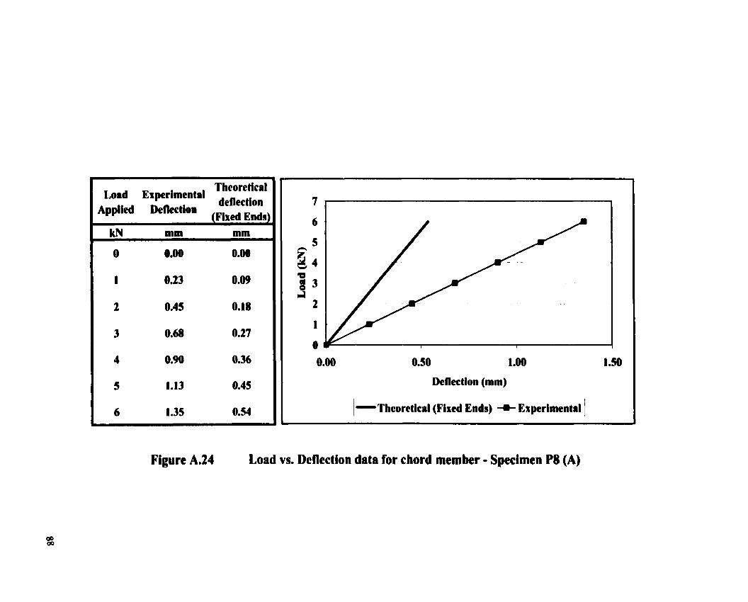
Figure A.24 Load vs. Deflection data for chord member - Specimen P8 (A)


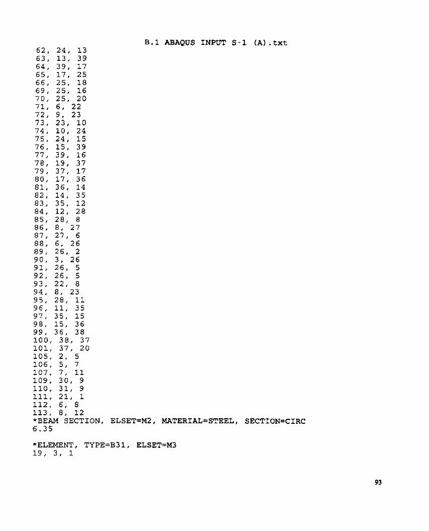
APPENDIX - B ABAQUS INPUT FILES

B. 1 ABAQUS INPUT S - 1 (A) . t x t *HEADING E R 1 TOWER SI Units (mm, N) *RESTART , WRITE **Mode1 Definition * * *NODE 1, o., o . , o . 2 , O . , O . , 914 .4 3, O . , 791 .718 , 457 .2
7 6 2 . f O . , O . , 5, 762 . , O . , 914.4, 6, 762 . , 791 .718, 457 .2 , 7 , 1 5 2 4 . , O . , 914 .4 8, 1 5 2 4 . , 791 .718, 457.2 , 9, 1 5 2 4 . , O, , O. ,
2286 . , O . , O . , 2 2 8 6 . , O . , 914 .4 , 2286 . , 791 .718, 4 5 7 . 2 , 3048 . , O . , O . , 3O48., O . , 914 .4 , 3048 . , 791 .718, 4 5 7 . 2 , 3810 . , O . , O . , 3810 , , 791 .718, 4 5 7 . 2 , 4572 . , O . , O . , 0572 . , O . , 914.4, 4 5 7 2 . , 791 .718, 457 .2 , 3 8 1 . , 395 .732, 228 .6 , 1 1 4 3 . , 395.732, 228 .6 , 1 9 0 5 . , 395 .732, 228 .6 , 2 6 6 7 . , 395 .732, 228.6, 4191., 395.732, 228 .6 , 3 8 1 . , 395 .732, 685.8, 1 1 4 3 , , 395 .732, 685.8, 1 9 0 5 . , 395 .732, 685.8, 381., O. , 457.2, 1 1 4 3 . , O . , 457.2, 1 9 0 5 . , o., 457.2, 2667 . , O . , 457.2, 3429 . , O . , 457.2, 4 1 9 1 . , O . , 457.2, 2667. , 395 .732, 685 .8 , 3 4 2 9 . , 395 .732, 685 .8 , 4191., 395.732, 6 8 5 . 8 , 3810 . , O . , 914.4, 3429 . , 395 .732, 228.6, 2667 . , O. , O. ,

B. 1 ABAQUS INPUT S - 1 (A) . tx t 4, 11, 14 5, 14, 38 6, 38, 19 7 , 3, 6 8, 6 , 9 9, 9, 12 10, 12, 15 11, 15, 17 12, 17, 20 13, 1, 4 14, 4, 7 18, 16, 18 103, 13, 40 104, 40, 10 108, 4, 9 *BEAM SECTION, ELSET=Ml8 MATERIAL=STEEL# SECTION=CIRC 19.05
B.1 ABAQUS INPUT S - 1 (A) . t x t
*BEAM SECTION, ELSET=M2, MATERIAL=STEEL, SECTION=CIRC 6.35

B.1 ABAQUS INPUT S-1 (A) . t x t 21, 2, 3 22, 20, 18 24, 19, 20 *BEAM SECTION, ELSET=M3, MATERIAL=STEEL, SECTION=CIRC 9 . 5 2 5
*ELEMENT, TYPE=B31, ELSET=M4 20,1,2,3 23,18,19,20 *BEAM SECTION, ELSET=M4, MATERIAL=STEEL, SECTION=CIRC 9.525
* STEP , PERTURBATION 6000N CONCENTRATED LOAD *STATIC *BOUNDARY 4, 2 5, 2 10, 2 13, 2 18, 1, 3 19, 1, 3 * CLOAD 40, 2, -6000 *ELPRINT *NODE PRINT 'il *END STEP
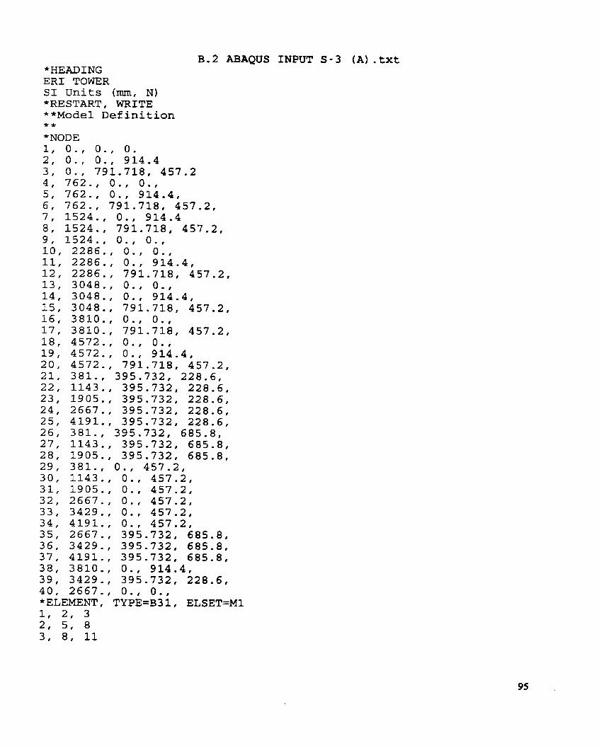
B.2 ABAQUS INPUT S - 3 (A) . t x t *HEADING E R 1 TOWER SI Units (mm, N) *RESTART, WRITE **Mode1 Definition * * *NODE 1, o., o. , o . 2, O . , O . , 914.4 3, O . , 791.718, 457.2 4 , 762. , O . , O. , 5, 762. , O , , 914.4, 6, 762. , 791.718, 457.2, 7 , 1524. , O. , 914.4 8, 1524. , 791.718, 457.2, 9 , 1524. , O . , O . ,
o . , o., O . , 914.4, 791.718, 457.2, o. , o., O. , 914.4, 791.718, 457.2, o. , O * , 791.718, 457.2, o . , o. , O . , 914 .4 , 791.718, 457.2,
381,, 395.732, 228.6, 1143. , 395.732, 228.6, 1905., 395.732, 228.6, 2667. , 395.732, 228.6, 4191. , 395.732, 228.6, 3 8 l . , 395.732, 685.8, 1143. , 395.732, 685.8, 1905. , 395.732, 685.8, 381. , O . , 457.2,
O * , 457 .2 , o . , 457.2, o . , 457.2 , o . , 457.2, o. , 457.2, 395.732, 685.8, 395.732, 6 8 5 . 8 , 395.732, 685.8 , O. , 914.4, 395.732, 228.6, o., o . ,
4, 11, 14 5, 14, 38 6, 38, 19 7 , 3, 6 81 6 , 9 9, 9, 12 10, 12, 15 11, 15, 17 12, 17, 20 13, 1, 4 14, 4, 7 18, 16, 18 103, 13, 40 104, 40, 10 108, 4 , 9 *BEAM SECTION, ELSET=Ml, MATERIAL=STEEL, SECTION=CIRC 25 - 4
B . 2 ABAQUS I N P U T S-3 (A) . t x t
100, 38, 37 101, 3 7 , 20 105, 2 , 5 106, 5, 7 107, 7, 11 109, 30, 9 110, 31, 9 111, 21, 1 112, 6, 8 113, 8, 12 *BEAM SECTION, ELSET=M2, MATERIAL=STEEL, SECTION=CIRC 7.15
B. 2 ABAQUS INPUT S - 3 (A) . t x t 21, 2, 3 22, 20, 18 24, 19, 20 *BEAM SECTION, ELSET=M3 9.525
*ELEMENT, TYPE=B31, ELSET=M4 20,1,2,3 23,18,19,20 *BEAM SECTION, ELSET=M4, MATERIAL=STEEL, 9.525
*STEP, PERTURBATION 6000N CONCENTRATED LOAD *STATIC * BOUNDARY 4, 2 5, 2 10, 2 13, 2 18, 1, 3 19, 1, 3 *CLOAD 40, 2, -6000 *ELPRINT *NODE PRINT U *END STEP

B.3 ABAQUS INPUT S - 5 (A) . t x t * H W I N G ER1 TOWER SI Units (mm, N) *RESTART, WRITE **Mode1 Definition * * *NODE 1, O,, o. , O. 2, O., O., 914.4 3, O., 791.718, 457.2 4, 762., O., O., 5, 762., O., 914.4, 6, 762., 791.718, 457.2, 7, 1524., O., 914.4 8, 1524., 791.718, 457.2, 9, 1524., O., O., 10, 2286., O., O., 11, 2286., O., 914.4, 12, 2286., 791.718, 457.2, 13, 3048., O., O., 14, 3048., O., 914.4, 15, 3048., 791.718, 457.2, 16, 3810,, O., O., 17, 3810., 791.718, 457.2, 18, 4572., O., O,, 19, 4572., O., 914.4, 20, 4572., 791.718, 457.2, 21, 381., 395.732, 228.6, 22, 1143., 395.732, 228.6, 23, 1905., 395.732, 228.6, 24, 2667., 395.732, 228.6, 25, 4191., 395.732, 228.6, 26, 381,, 395.732, 685.8, 27, 1143., 395.732, 685.8, 28, 1905., 395.732, 685.8, 29, 381., O., 457.2, 30, 1143., O., 457.2, 31, 1905., O., 457.2, 32, 2667. , O., 457.2, 33, 3429., O., 457.2, 34, 4191., O., 457.2, 35, 2667., 395.732, 685.8, 36, 3429., 395.732, 685.8, 37, 4191., 395.732, 685.8, 38, 3810., O., 914.4, 39, 3429., 395.732, 228.6, 40, 2667., O., O., *ELEMENT, TYPE=B31, ELSET=Ml 1, 2, 3 2, 5 , 8 3, 8, 11

B.3 ABAQUS INPUT S-5 (A) . t x t 4, 11, 14 5, 14, 38 6, 38, 19 71 3, 6 8, 6 , 9 9 , 9, 1 2 10, 12, 15 11, 15, 17 12, 17, 20 13, 1, 4 14, 4, 7 18, 16, 18 103, 13, 40 104, 40, 10 108, 4, 9 *BEAM SECTION, ELSET=Ml, MATERIAL=STEEL, SECTION=CIRC 3 4 . 9 5
B.3 ABAQUS INPUT S-5 (A) . t x t
100, 38, 37 101, 3 7 , 20 105, 2, 5 106, 5 , 7 107, 7, 11 109, 30, 9 110, 31, 9 111, 21, 1 112, 6, 8 113, 8, 1 2 "BEAM SECTION, ELSET=MS, MATERIAL=STEEL, SECTION=CIRC 7.95
B. 3 ABAQUS INPUT S - 5 (A) . t x t 21, 2, 3 22, 20, 18 24, 19, 20 *BEAM SECTION, ELSET=M3, MATERIAL=STEEL, SECTION=CIRC 9 . 5 2 5
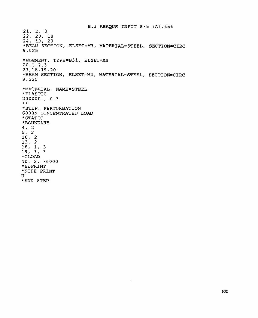
*ELEMENT, TYPE=B31, ELSETzM4 20,1,2,3 23,18,19,20 *BEAM SECTION, ELSET=M4, MATERIAL=STEEL, SECTION=CIRC 9 . 5 2 5
*STEP, PERTURBATION 6000N CONCENTRATED LOAD *STATIC * BOUNDARY 4, 2 51 2 10, 2 13, 2 18, 1, 3 19, 1, 3 *CLOAD 40, 2, -6000 *ELPRINT *NODE PRINT u *END STEP

VITA AUCTORIS
Adnan Karim Qureshi was born in 1971 in Hala, a city of Province of Sind, Pakistan. He
graduated from Public School Hyderabad in 1988. From there he went to Mehran
University of Engineering & Technology, Jamshoro, Pakistan, where he obtained h i s
Bachelor's with Honors in Civil Engineering in 1 995. Mer his Bachelor's he worked for
about three years in the field of Civil Engineering in Pakistan and in Norway.
He is currently a candidate for the Master's degree in Structural Engineering at the
University of Windsor and hopes to graduate in Fall 1999.