Effective Floor Cavity and Knee Wall Construction ... · construction techniques and cost-effective...
10
Effective Floor Cavity and Knee Wall Construction Techniques in Two-Story Homes in Hot Climates FSEC-PF-467-16 December 2016 Presented at ASHRAE Thermal Performance of the Exterior Envelopes of Whole Buildings XIII International Conference, Clearwater, FL – December 2016 Author Charles R. Withers, Jr. This article or paper was published in the ASHRAE Thermal Performance of the Exterior Envelopes of Whole Buildings XIII International Conference Proceedings. Copyright 2016 ASHRAE. Reprinted by permission at www.fsec.ucf.edu. This article may not be copied and/or distributed electronically or in paper form without permission of ASHRAE. For more information, visit www.ashrae.org. Requests from third parties for use of ASHRAE published content should be directed to www.ashrae.org/permissions. ASHRAE 1791 Tullie Circle, NE, Atlanta, Georgia 30329-2305 phone: 404-636-8400 • fax: 404-321-5478 • web: http://www.ashrae.org
Transcript of Effective Floor Cavity and Knee Wall Construction ... · construction techniques and cost-effective...
Effective Floor Cavity and Knee Wall Construction Techniques in Two-Story Homes in Hot Climates
FSEC-PF-467-16
December 2016
Presented at
ASHRAE Thermal Performance of the Exterior Envelopes of Whole Buildings XIII International Conference, Clearwater, FL – December 2016
Author
Charles R. Withers, Jr. This article or paper was published in the ASHRAE Thermal Performance of the Exterior Envelopes of Whole Buildings XIII International Conference Proceedings. Copyright 2016 ASHRAE. Reprinted by permission at www.fsec.ucf.edu. This article may not be copied and/or distributed electronically or in paper form without permission of ASHRAE. For more information, visit www.ashrae.org. Requests from third parties for use of ASHRAE published content should be directed to www.ashrae.org/permissions.
ASHRAE
1791 Tullie Circle, NE, Atlanta, Georgia 30329-2305 phone: 404-636-8400 • fax: 404-321-5478 • web: http://www.ashrae.org
Disclaimer The Florida Solar Energy Center/University of Central Florida nor any agency thereof, nor any of their employees, makes any warranty, express or implied, or assumes any legal liability or responsibility for the accuracy, completeness, or usefulness of any information, apparatus, product, or process disclosed, or represents that its use would not infringe privately owned rights. Reference herein to any specific commercial product, process, or service by trade name, trademark, manufacturer, or otherwise does not necessarily constitute or imply its endorsement, recommendation, or favoring by the Florida Solar Energy Center/University of Central Florida or any agency thereof. The views and opinions of authors expressed herein do not necessarily state or reflect those of the Florida Solar Energy Center/University of Central Florida or any agency thereof.

Effective Floor Cavity and Knee Wall Construction Techniques in Two-Story Homes in Hot Climates
Charles R. Withers, Jr.
ABSTRACT
It is understood that the floor cavity between the first and second floors of residential construction should be isolated fromunconditioned space by an effective air and thermal barrier. Although the construction materials utilized likely have reasonableair and thermal resistance, the application may not be applied correctly or some applications may not hold up well over time.A research project of existing homes (Withers and Kono 2015) measured impacts from this problem and identified durableconstruction techniques and cost-effective repairs. Floor cavity pathways to unsealed attics combined with natural or mechanicaldriving forces result in air transport between the attic and the floor cavity. Unconditioned air leakage into residential floor cavitieshas been found to cause elevated space-conditioning costs, increase peak electric utility demand, and cause moisture-related prob-lems.
This paper provides new research on measured cooling and heating impacts from floor cavity and knee wall repair. Overall,56 multistory homes were inspected and had performance tests completed, with 12 monitored for energy savings from floor cavityand some knee wall repairs. This paper describes practical inspection, testing, and dependable construction methods. Construc-tion methods discussed consider challenges such as contractor experience, limited working access, and complex structural geom-etry. The measured energy savings from floor cavity repairs combined with cost-effective repair methods in 12 homes was foundto be able to pay for repairs in about 3 to 4 years. Evidence from one home has shown that significant building moisture damagewas eliminated as a result of floor cavity repair.
INTRODUCTION
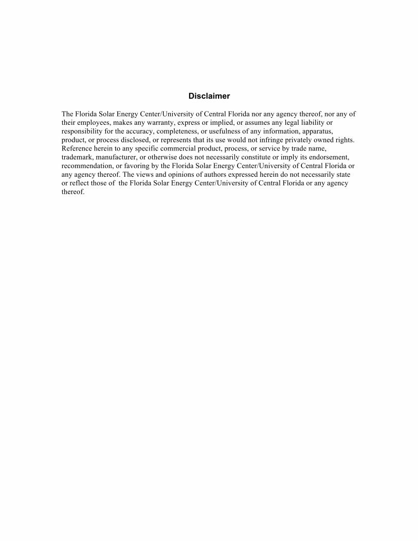
Floor cavities are assumed to be an interstitial spacewithin the primary air and thermal barrier of the home;however, even relatively minor defects around this space canhave negative consequences. Portions of floor cavities areoften exposed to attic spaces. Attic air can be transported intofloor cavities through natural or mechanical forces. Naturalforces such as wind can drive air through attic venting andcreate pressure differentials able to drive unconditioned airinto floor cavities (Figure 1). The term wind washing is some-times used to describe this. Wind washing is a general termreferring to diminished thermal control caused by air move-ment over or through an intended thermal barrier. Given theextreme thermal conditions of vented attics, convective air
transport can still transport air into floor cavity openings, evenwithout wind forces. Mechanical forces induced by duct leak-age can also create pressure differentials that will move uncon-ditioned air into and out of floor cavities. During hot humidweather, condensation may occur on cold supply duct surfaceswithin the floor cavity, resulting in ceiling moisture damage.In cold climates, cold air from wind washing can chill surfaceswithin the interior floor space and result in frozen water pipesin severe cases. Besides potential building damage, dimin-ished comfort and increased space-conditioning energy usemay also result from poorly insulated and sealed floor cavities.Enlightened contractors already understand the importance ofcreating a barrier between floor cavities and attics, but failurescontinue to occur, and older construction has a legacy of fail-
© 2016 ASHRAE
Charles R. Withers, Jr. is a senior research analyst at Florida Solar Energy Center, a research institute of the University of Central Florida,Cocoa, FL.
ures. An adequate air and thermal barrier may have beeninstalled but another trade penetrated or removed portionswithout repairing it. In the worst cases there are no air or ther-mal barriers installed at all.
BACKGROUND
The past emphasis on wind washing has concentrated onU-factor impacts and specific types of construction or scenar-ios (Bankvall 1978; Harrje et al. 1985; Lecompte 1990; Silber-stein et al. 1991; Uvslokk 1996; Janssens and Hens 2007).Knee wall, floor cavity, and wind washing problems have beenrecognized in other published literature, such as that by Sidall(2009), Lstiburek (2005), and EERE (2012), which providedsome information on best practices in specific applications.While wind washing has been known about for years, therehad been no obtainable published results associated withmeasured energy impacts or cost-benefit analysis of retrofitopportunities. This paper is based upon results from morerecent wind washing research in Florida carried out in twophases. The first phase resulted in published results coveringdetails on the study method and results but was limited tomeasured cooling energy impacts in six homes (Withers andCummings 2010; Cummings and Withers 2012). A secondphase was added to increase sample size and measure heatingand cooling impacts in six more homes (Withers and Kono2015). The primary goal of the Florida study was to evaluateinspection methods and determine the cost-effectiveness of
retrofit solutions for wind washing in two-story homes in hothumid climates. The retrofit solutions covered here may alsobe applied to new construction primarily in hot- or warm-dominant climate regions.
INSPECTION METHODS
House performance-related tests were completed in 56Florida single-family multistory homes of various ages. Thepurpose of the house tests was to gather data relevant to windwashing and to find reasonable candidates for monitoring andretrofit. The field assessments characterized wind washingfailures of the house air and thermal boundary. Assessmentsincluded a house tightness test, primary air boundary evalua-tion, air differential pressure mapping, air leakage assessment,duct leakage assessment, infrared scans of house surfaces, andvisual inspections.
A comprehensive visual inspection completed withinthe attic focused around floor cavities or dropped ceilingareas was found to be the most important and effectivemethod of identifying homes needing floor cavity repair.Figure 1b shows a commonly found issue of poorly fit kneewall insulation and areas of floor cavity open to attic spacescommonly over garage areas. Inspections should focusefforts on locating an effective air and thermal barrier overthe floor cavity. Some homes have very small attic areas thatwere either inaccessible or had limited accessibility forinspection. Equipment such as a bore scope may be needed
(a) (b)
Figure 1 (a) Conceptual illustration of wind washing through floor cavity shown on a floor plan. (b) View from within atticof poorly insulated knee wall and floor cavity with areas of missing and compressed batts. Batts were dirty fromyears of air movement across them. Attic soffit vent is nearby in dark left region of photo.
349 Thermal Performance of the Exterior Envelopes of Whole Buildings XIII International Conference
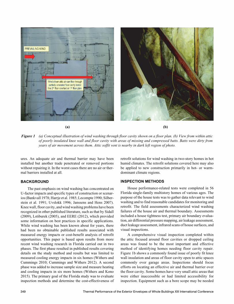
in such cases, or material disassembly may be warranted insome instances, such as moisture damage issues. Figure 2shows an example where soffit venting was removed forinspection in areas where floor cavities terminated nearby ina home with severe moisture damage found to be related tofloor cavity wind washing. Spray foam applications can also
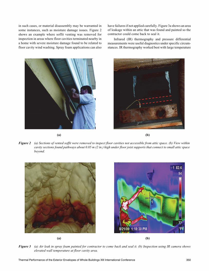
have failures if not applied carefully. Figure 3a shows an areaof leakage within an attic that was found and painted so thecontractor could come back to seal it.
Infrared (IR) thermography and pressure differentialmeasurements were useful diagnostics under specific circum-stances. IR thermography worked best with large temperature
(a) (b)
Figure 2 (a) Sections of vented soffit were removed to inspect floor cavities not accessible from attic space. (b) View withincavity sections found pathways about 0.05 m (2 in.) high under floor joist supports that connect to small attic spacebeyond.
(a) (b)
Figure 3 (a) Air leak in spray foam painted for contractor to come back and seal it. (b) Inspection using IR camera showselevated wall temperature at floor cavity area.
Thermal Performance of the Exterior Envelopes of Whole Buildings XIII International Conference 350
differentials occurring between attic and indoors for at least afew hours. Figure 3b shows warm summer indoor walltemperatures due to wind washing into the floor cavity. This isthe same home of the floor plan shown in Figure 1a. At timesthis author found it more useful to use the IR camera fromwithin the attic looking at knee wall and floor cavity areasinstead of from indoors.
An indication of whether the floor cavity is more indoorsthan outdoors regarding the primary air barrier was evaluatedusing differential pressure (dp) measurements while the housewas depressurized to 0.2 in. w.c. (50 Pa) with reference tooutside. This diagnostic can be performed quickly if a housetightness test is already planned. The project evaluation resultsindicated that this diagnostic was clearly not adequate on itsown to be a replacement of visual inspection to determine if afloor cavity has a significant potential for wind washing (With-ers and Kono 2015). Measuring the house pressure with refer-ence to the floor cavity could be considered a simple and quickdiagnostic test that can be done to determine if more detailedvisual investigation of the floor cavity is warranted, particu-larly if the measurement is between –0.136 in. w.c. (–34 Pa) to0 in. w.c. (0 Pa) (house depressurized). The dp diagnosticcould be useful to prompt a more careful visual inspection andto consider possible leakage to areas not easily accessible thatmay require some disassembly.
WHY TIGHT INSULATED FLOOR CAVITIES MATTER
Inadequately insulated and sealed floor cavities can resultin occupant health and comfort problems, building damage,and elevated heating and cooling costs. Sealed floor cavitiesalso help minimize duct leakage impacts occurring withinthese spaces. Return duct leakage decreased 37% and supplyleakage decreased by 38% from sealing floor cavities andmaking no direct repairs to ducts in 10 homes. This is notsurprising since ducts were located within the floor cavity ofall these homes. Sealing the floor cavity is a more cost-effec-tive way to limit duct leakage impacts within the floor cavitiesof existing constructions. House airtightness, ACH50, became11% tighter and homes with vented recessed can lights in thefloor cavity had house tightness reductions double (23%tighter). ACH50 is an industry measure of building airtightnessmeasured at a pressure of 0.2 in. w.c. (50 Pa) and normalizedby the house conditioned volume. Implementing good prac-tice in new construction would not necessarily add cost ifcurrent building codes are followed and enforced. Failure toimplement good practice or damage created by trades mayhave an average cost of repair around $350. The range inhomeowner repair cost can vary widely depending uponparticular circumstances and materials used—from as little as$170 up to $800 or more in very large homes.
Moisture Issues
In heating-dominant climates, water damage within thefloor cavity is most likely to occur due to water pipe freezedamage resulting in water leakage or condensation on cold
building surfaces. Weatherization programs have worked atimproving this in older homes over the years, but a breach ordegradation over time can increase the potential of this prob-lem during prolonged severe winter conditions. Cooling-dominated climates are more likely to experience moistureissues in the summer due to condensation on cool duct orbuilding surfaces and material damage associated with mois-ture absorption under specific circumstances. One of thehomes had severe moisture damage exhibited by mold andmildew stains on first-floor ceilings occurring under coldsupply air ducts, severely warped wood flooring on the secondfloor, and cracked wood and paint on sections of stair risers.Photos and additional details on this can be found in the paperby Withers and Cummings (2010). Prior to repair, a section offaced batt that had been wrapped around a cold air supply ductwhere it entered the floor cavity was found to be drenched incondensation. Wood moisture content was measured beforeand after floor cavity repairs in this home during hot andhumid weather. Moisture content in wood stair sections clos-est to the floor cavity were at 13.1% and gradually decreasedto 9.5% on lower sections farther away from the floor cavity.Interior air conditions were cool and dry and wood furniturehad a moisture content around 7% to 8% by comparison,which is expected for an air-conditioned space. The averagestair moisture content decreased to 9.0% after repair andcracks in paint and wood stair risers decreased within a fewweeks of repair. Evidence of duct condensation also stoppedafter repair. Other homes in the Florida study did not exhibitsuch severe moisture problems. The severe moisture issues inthis home were attributed to severe floor cavity leakage onopposing sides of the home (complimentary pathways)oriented in line with daily occurring wind combined with theoccupant preference for low interior summer temperatures(73°F [22.8°C] overnight and 76°F [24.4°C] daytime).
Energy
Overall cooling energy savings resulting from floorcavity repair varied from 1% up to 33%, and heating savingsvaried from 0% to 39%. It was not surprising that some homesdid not demonstrate high energy savings, since the studyhomes had varying degrees of thermal bypass issues. The casewith no heating savings is most attributed to mild winter moni-toring conditions and the preference for low heating set point,which did not provide much heating data for analysis. Thepreviously discussed house with severe moisture issues had8% cooling savings, but it was a large upscale home that useda lot of cooling energy, so the annual cooling energy savingsof 2770 kWh/yr and peak cooling reduction of 1.8 kW werequite large. Table 1 shows the predicted annual and peakenergy savings based on 12 homes; heating results are basedon 5 homes. Regression least-squares best-fit analysis wasperformed from monitored heating and cooling data alongwith local monitored indoor and outdoor conditions for eachhome to create equations that could be used with typical mete-orological year (TMY) data of four Florida cities to predict the
351 Thermal Performance of the Exterior Envelopes of Whole Buildings XIII International Conference
annual cooling and heating savings for typical weather condi-tions. The average predicted annual cooling and heating energysavings was 1034 kWh per home from wind washing repairs.This was potentially $119 saved each year by each homeownerbased on an average rate of $0.115/kWh. The savings can beexpected to last as long as the home, because the repair lifetimehas no limit under reasonable circumstances. These results arelimited here to represent hot and humid climate regions; moni-toring in colder climate regions should be done to more accu-rately reflect regional construction practice and measurementunder much more extreme winter conditions.
SEALING FLOOR CAVITY AREAS EXPOSED TO ATTIC SPACES
New Construction
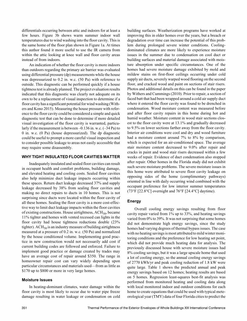
Good air and thermal barriers begin with a good design.First, designs should not place structural members withinabout 18 in. (0.45 m) of the floor cavity or knee wall to allowroom to correctly install continuous sections of air and thermalbarrier materials. This distance is less critical if spray foam isused to insulate and seal the floor cavity and knee walls.Figure 4a shows structural members directly against the floorcavity, which makes it difficult to install a continuous air andthermal barrier with faced batts. Figure 4b shows the roof trussfurther away from the plywood placed over the knee wall andfloor cavity. The continuity of air barrier should be maintainedfrom the roof deck at top of knee wall, covering the knee wall,and continuing down over the floor cavity opening and ontodrywall of first floor below. If rigid panels or fabric-based airbarrier are used, all panel seams should be sealed with mate-rials appropriate for attic conditions. Insulation should beapplied with approved mechanical fastening materials andmethods. This is especially important for thick batts. If appliedmeticulously, kraft-faced batts have the potential to performwell and to be the lowest-cost option. However, the long-termdurability is less certain than rigid or spray-applied materials.New homes with batt insulation are more likely to use R-30batts. Batts are prone to sag in vertical installations, do nothold up well to physical impacts, and are not typically repairedafter intentional displacement or penetration. Since ducts,
Table 1. Predicted Average Annual and Peak Energy Cooling and Heating Impacts
from Floor Cavity Repairs
Annual Cooling
kWh
Summer Peak Hour
Cooling kW
Annual Heating
kWh
Winter Peak Hour
Heating kW
Pre-repair 9392 3.66 502 1.86
Post-repair 8483 3.27 378 1.53
Savings 909 0.39 125 0.33
Savings % 9.7% 10.7% 24.9% 18.7%
(a) (b)
Figure 4 (a) Existing construction showing multiple truss sections tightly against each other and the knee wall and floor cavitystructure that does not allow sheet stock to simply be applied continuously as cover. (b) New construction shown usesplywood sheet over knee wall and floor cavity sections with room to seal seams and add insulation to improve wallR-value.
Thermal Performance of the Exterior Envelopes of Whole Buildings XIII International Conference 352
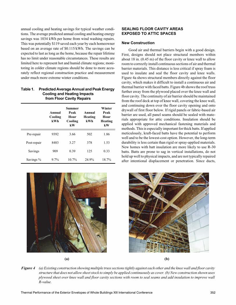
wires, and pipes are typically run inside floor cavities, eachtrade should be held responsible for maintaining the integrityof the air and thermal barrier around their work. Protect coldsupply ducts from condensation in vented attics wheneverenvelope insulation is placed in contact with the exterior ductsurface (see Figure 5), particularly in cooling-dominatedclimates. Condensation potential can be decreased by wrap-ping ducts at contact points with a thin insulative wrap havingan exterior vapor barrier before insulation is placed in contactwith it. This cannot guarantee that condensation will neveroccur, but it has been demonstrated to work in homes withcooling set points maintained above 74°F (23.3°C). In regardto limiting general water vapor issues, materials with lowvapor permeability, less than 1, should not be placed on thedominantly coldest side of a wall/cavity barrier assembly.
Existing Construction
Implementing repairs in existing construction can be morechallenging. Two basic methods were implemented within theFlorida study. One method used low-density spray foam and theother used well-placed kraft-faced insulation batts. Floor cavityand knee wall wind washing repairs typically use much lessinsulation material than is common in conventional insulationjobs. The average repair area was 169 ft2 (15.7 m2) with a rangeof 48–510 ft2 (4.5–47.4 m2). The relatively small repair area andhigh mobilization cost of spray foam rigs can make repair byspray foam twice as costly as using batts or insulated boardstock. Low-density spray foam had a starting cost of at least$370 but is more likely to be around $650, compared to batts,which could average more around $300. Homes with garage
attic space next to second-story floor space (the most commonlocation) generally have easy access and often require less than40 ft2 (3.7 m2) of material to seal and insulate the floor cavityfrom the attic. If the knee wall is also insulated, the total areatypically increases to 70–100 ft2 (6.5–9.3 m2). Repair cost of aneasy-to-access floor cavity and knee wall area of about 100 ft2
(9.3 m2) and 2.8 person-hours could cost as little as $173 andeven less, at about $85, if only the floor cavity is sealed withfaced batt and sealant. Of all homes having floor cavity path-ways, about 25% of those inspected had very small leakagepathways (longitudinal seams) that could be sealed inexpen-sively using canned expansive foams for perhaps as little as$20–$40 in retail material costs.
An example of a repair using faced batts is shown inFigure 6. The kraft face is intended to perform as the air barrierso it must be carefully sealed to the rigid materials around theperimeter of the floor cavity. Figure 6b shows the kraft facingthe attic. To comply with fire-related building codes, thefacing should not be left exposed to the attic. The facing wasplaced in this way to show how it must be able to seal aroundthe perimeter and framing members. The correct way to installis to generously apply an appropriate construction adhesive,caulk, or foam on the entire perimeter of floor cavity and applythe kraft face against the adhesive towards the inside of thecavity with the unfaced insulation side visible from the attic.The batt should also be mechanically fastened to the perimeterusing staples. If preferred, an air-barrier wrap or rigid boardstock could also be used as the air barrier in place of faced battas long as it is also covered by an appropriate code-approvedignition and thermal barrier.
(a) (b)
Figure 5 (a) The cold air supply duct is first wrapped using a thin insulation sheet with a vapor barrier on the exterior face.(b) Then insulation can be placed around and in contact with the barrier wrap, where a low-density spray foam wasused.
353 Thermal Performance of the Exterior Envelopes of Whole Buildings XIII International Conference

While using relatively inexpensive materials (such askraft-faced insulation batts) can result in lower installationcosts, specific installation details must be carefully followedto ensure effective air and thermal barrier performance.Materials have to be carefully cut to fit within framing, befastened mechanically, and have a functional air seal. Tightattic spaces or complex framing require much more labor andskill to apply the inexpensive materials and the final resultsare less likely to be successful compared to spray foam. Ifduct leakage is known to exist within the floor cavity, anairtight seal is even more important. Therefore, spray-applied low-density foam may be the best choice in certaincircumstances. 2012 International Residential Code,Section R316.5.3 (ICC 2012), requires a fire ignition barrieron foam insulation exposed in attic spaces. Some manufac-turers may accomplish this by spraying the attic exposedfoam with a code-approved fire ignition barrier coating, alsoreferred to as an intumescent material. Mineral fiber or cellu-lose insulation 1.5 in. (0.038 m) thick or 1/4 in. (0.0064 m)thick hardboard or wood structural panel are some otherexamples of approved ignition barrier materials noted in thiscode. One should be aware of local code requirements andpractices that may vary from this.
CONCLUSION
Floor cavities can be insulated and sealed with a varietyof materials relatively inexpensively in well-designed newconstruction. In retrofits, the primary consideration is cost andlimitation of the work space. Using materials readily availableat home improvement stores will likely be less expensive than
using spray-applied foams. However, that alone does notimply the lowest-cost materials are the best choice. Complexstructural geometry and tight restrictive working environ-ments may make it difficult and even impossible to make goodairtight installations that maintain continuity of the air andthermal barriers. Low-cost material such as faced batt insula-tion is more prone to damage in areas occasionally accessed bytrades or homeowners. Therefore, spray-applied foams maybe the best or only choice in certain circumstances. Methodsdiscussed in this paper managed moisture, decreased air leak-age, and reduced energy in a hot-and-humid-dominantclimate. However, local codes and best local practices shouldbe followed along with application by knowledgeable contrac-tors to help ensure a safe, healthy, and durable result in otherclimate regions.
Based on monitoring results in Florida, the total annualestimated energy savings from repair was 1034 kWh/year. Ata cost of $0.115/kWh, this equates to $119/year saved inconsumer energy costs. It is believed that the average cost ofrepair could be $350, assuming about 75% of homes can besealed by professional contractors using off-the-shelf air andthermal barrier products and the other 25% are sealed usingprofessionally applied low-density spray foam. The averagesimple payback would be about three years. Average peakcooling and heating reduction were about 0.3 kW and 0.4 kW,respectively, providing additional benefit to electric utilitiesand consumers with peak use charges.
(a) (b)
Figure 6 (a) An open dropped ceiling connected to a large open floor cavity was sealed and insulated using faced batts.(b) The batt paper facing should not be left exposed to the attic. Consult local codes to address approved fire safetypractices for each specific type of repair.
Thermal Performance of the Exterior Envelopes of Whole Buildings XIII International Conference 354
ACKNOWLEDGMENTS
This paper would not have been possible without researchsupport from the U.S. Department of Energy Building Amer-ica Program and Florida Power & Light. Jim Cummings,retired PI from Florida Solar Energy Center, is acknowledgedfor initiating the interest in this research and project manage-ment during the Florida research study.
REFERENCES
Bankvall, C.G. 1978. Forced convection: Practical thermalconductivity in an insulated structure under the influ-ence of workmanship and wind. In Thermal transmis-sion measurements of insulation. ASTM STP660, pp.409–25. West Conshohocken, PA: ASTM International.
Cummings, J., and C.R. Withers, Jr. 2012. Envelope thermalfailures due to wind washing in two-story homes. Pro-ceedings of the 3rd Conference on Building EnclosureScience and Technology, Atlanta, GA.
EERE. 2012. Energy renovations: Volume 17: Insulation—Aguide for contractors to share with homeowners. Wash-ington, DC: U.S. Department of Energy, Energy Effi-ciency and Renewable Energy. http://apps1.eere.energy.gov/buildings/publications/pdfs/building_america/insulation_guide.pdf.
Harrje, D.T., G.S. Dutt, and K.J. Gadsby. 1985. Convectiveloop heat losses in buildings. ASHRAE Transactions91(2):751–60.
ICC. 2012. 2012 International Residential Code. Geneva:International Code Council.
Janssens, A., and H. Hens. 2007. Effects of wind on thetransmission heat loss in duo-pitched insulated roofs: Afield study. Energy and Buildings 39(9):1047–54.
Lecompte, J. 1990. The influence of natural convection onthe thermal quality of insulated cavity construction.Building Research and Practice 6:349–54.
Lstiburek, J. 2005. Chapter 8. In Builder’s guide to hot-humid climates, pp. 219–23. Westford, MA: BuildingScience Press.
Sidall, M. 2009. The impact of thermal bypass. Green Build-ing Magazine 19(1):16–23.
Silberstein, A., E. Arquis, and D.J. McCaa. 1991. Forcedconvection effects in fibrous insulation. In Insulationmaterials: Testing and applications, 2nd vol. ASTMSTP1116, pp. 292–309. West Conshohocken, PA:ASTM International.
Uvsløkk, S. 1996. The importance of wind barriers for insu-lated timber frame constructions. Journal of ThermalInsulation and Building Envelopes 20:40–62.
Withers, C., and J. Cummings. 2010. Opportunities forenergy conservation and improved comfort from windwashing retrofits in two-story homes—Part II. Proceed-ings of the 17th Symposium on Improving Building Sys-tems in Hot and Humid Climates, Austin, TX.
Withers, C., and J. Kono. 2015. Investigating solutions towind washing issues in two-story Florida homes—Phase 2. Report DOE/GO-102015-4595. Golden, CO:National Renewable Energy Laboratory.
355 Thermal Performance of the Exterior Envelopes of Whole Buildings XIII International Conference