Effective February 2013 Product Application …pub/@electrical/... · Effective February 2013...
36
Effective February 2013 Supersedes April 2005 Product Application AP05013001E eas yRelay applications Contents Showroom and store window lighting Operating description ...................... 2 Control circuit ............................ 2 List of operands........................... 3 Benefits ................................. 3 Examples ................................ 3 Floor lighting Operating description ...................... 4 Control circuit ............................ 4 List of operands........................... 4 Benefits ................................. 5 Examples ................................ 5 Belt sequence control for three conveyor belts with motor monitoring Operating description ...................... 6 Control circuit ............................ 6 Load circuit .............................. 6 List of operands........................... 7 Benefits ................................. 7 Examples ................................ 7 Greenhouse temperature and ventilation control Operating description ...................... 9 Control circuit ........................... 10 Load circuit ............................. 10 Sample switching points ................... 10 List of operands.......................... 10 Benefits ................................ 11 Examples ............................... 11 Lighting control in a production room Operating description ..................... 12 Control circuit ........................... 13 Load circuit ............................. 13 Switching points of the daylight control switch. . 13 List of operands.......................... 13 Benefits ................................ 13 Examples ............................... 14 Booster pumps Operating description ..................... 15 Control circuit ........................... 16 Load circuit ............................. 16 Pressure diagram. . . . . . . . . . . . . . . . . . . . . . . . . 16 Switching points ......................... 16 List of operands.......................... 16 Benefits ................................ 17 Examples ............................... 17 Tank installation level indicator Operating description ..................... 18 Control circuit ........................... 19 List of operands.......................... 19 Benefits ................................ 19 Examples ............................... 20 Access monitoring for a parking garage Operating description ..................... 21 Control circuit ........................... 21 List of operands.......................... 22 Benefits ................................ 22 Examples ............................... 22 Time-controlled lighting system Operating description ..................... 23 Control circuit ........................... 23 List of operands.......................... 24 Benefits ................................ 24 Examples ............................... 24 Refrigeration control system Operating description ..................... 26 Control circuit ........................... 26 Load circuit ............................. 26 List of operands.......................... 26 Benefits ................................ 27 Examples ............................... 27 Perimeter advertising in a stadium Operating description ..................... 28 Control circuit ........................... 28 List of operands.......................... 28 Benefits ................................ 29 Examples ............................... 29 Rolling door control Operating description ..................... 30 Control circuit ........................... 31 Load circuit ............................. 31 List of operands.......................... 31 Examples ............................... 32
Transcript of Effective February 2013 Product Application …pub/@electrical/... · Effective February 2013...
Effective February 2013
Supersedes April 2005Product Application AP05013001E
easyRelay applications
Contents
Showroom and store window lightingOperating description . . . . . . . . . . . . . . . . . . . . . . 2Control circuit . . . . . . . . . . . . . . . . . . . . . . . . . . . . 2List of operands . . . . . . . . . . . . . . . . . . . . . . . . . . . 3Benefits . . . . . . . . . . . . . . . . . . . . . . . . . . . . . . . . . 3Examples . . . . . . . . . . . . . . . . . . . . . . . . . . . . . . . . 3
Floor lightingOperating description . . . . . . . . . . . . . . . . . . . . . . 4Control circuit . . . . . . . . . . . . . . . . . . . . . . . . . . . . 4List of operands . . . . . . . . . . . . . . . . . . . . . . . . . . . 4Benefits . . . . . . . . . . . . . . . . . . . . . . . . . . . . . . . . . 5Examples . . . . . . . . . . . . . . . . . . . . . . . . . . . . . . . . 5
Belt sequence control for three conveyor belts with motor monitoringOperating description . . . . . . . . . . . . . . . . . . . . . . 6Control circuit . . . . . . . . . . . . . . . . . . . . . . . . . . . . 6Load circuit . . . . . . . . . . . . . . . . . . . . . . . . . . . . . . 6List of operands . . . . . . . . . . . . . . . . . . . . . . . . . . . 7Benefits . . . . . . . . . . . . . . . . . . . . . . . . . . . . . . . . . 7Examples . . . . . . . . . . . . . . . . . . . . . . . . . . . . . . . . 7
Greenhouse temperature and ventilation controlOperating description . . . . . . . . . . . . . . . . . . . . . . 9Control circuit . . . . . . . . . . . . . . . . . . . . . . . . . . . 10Load circuit . . . . . . . . . . . . . . . . . . . . . . . . . . . . . 10Sample switching points . . . . . . . . . . . . . . . . . . . 10List of operands . . . . . . . . . . . . . . . . . . . . . . . . . . 10Benefits . . . . . . . . . . . . . . . . . . . . . . . . . . . . . . . . 11Examples . . . . . . . . . . . . . . . . . . . . . . . . . . . . . . . 11
Lighting control in a production roomOperating description . . . . . . . . . . . . . . . . . . . . . 12Control circuit . . . . . . . . . . . . . . . . . . . . . . . . . . . 13Load circuit . . . . . . . . . . . . . . . . . . . . . . . . . . . . . 13Switching points of the daylight control switch. . 13List of operands . . . . . . . . . . . . . . . . . . . . . . . . . . 13Benefits . . . . . . . . . . . . . . . . . . . . . . . . . . . . . . . . 13Examples . . . . . . . . . . . . . . . . . . . . . . . . . . . . . . . 14
Booster pumpsOperating description . . . . . . . . . . . . . . . . . . . . . 15Control circuit . . . . . . . . . . . . . . . . . . . . . . . . . . . 16Load circuit . . . . . . . . . . . . . . . . . . . . . . . . . . . . . 16Pressure diagram. . . . . . . . . . . . . . . . . . . . . . . . . 16Switching points . . . . . . . . . . . . . . . . . . . . . . . . . 16List of operands . . . . . . . . . . . . . . . . . . . . . . . . . . 16Benefits . . . . . . . . . . . . . . . . . . . . . . . . . . . . . . . . 17Examples . . . . . . . . . . . . . . . . . . . . . . . . . . . . . . . 17
Tank installation level indicatorOperating description . . . . . . . . . . . . . . . . . . . . . 18Control circuit . . . . . . . . . . . . . . . . . . . . . . . . . . . 19List of operands . . . . . . . . . . . . . . . . . . . . . . . . . . 19Benefits . . . . . . . . . . . . . . . . . . . . . . . . . . . . . . . . 19Examples . . . . . . . . . . . . . . . . . . . . . . . . . . . . . . . 20
Access monitoring for a parking garageOperating description . . . . . . . . . . . . . . . . . . . . . 21Control circuit . . . . . . . . . . . . . . . . . . . . . . . . . . . 21List of operands . . . . . . . . . . . . . . . . . . . . . . . . . . 22Benefits . . . . . . . . . . . . . . . . . . . . . . . . . . . . . . . . 22Examples . . . . . . . . . . . . . . . . . . . . . . . . . . . . . . . 22
Time-controlled lighting systemOperating description . . . . . . . . . . . . . . . . . . . . . 23Control circuit . . . . . . . . . . . . . . . . . . . . . . . . . . . 23List of operands . . . . . . . . . . . . . . . . . . . . . . . . . . 24Benefits . . . . . . . . . . . . . . . . . . . . . . . . . . . . . . . . 24Examples . . . . . . . . . . . . . . . . . . . . . . . . . . . . . . . 24
Refrigeration control systemOperating description . . . . . . . . . . . . . . . . . . . . . 26Control circuit . . . . . . . . . . . . . . . . . . . . . . . . . . . 26Load circuit . . . . . . . . . . . . . . . . . . . . . . . . . . . . . 26List of operands . . . . . . . . . . . . . . . . . . . . . . . . . . 26Benefits . . . . . . . . . . . . . . . . . . . . . . . . . . . . . . . . 27Examples . . . . . . . . . . . . . . . . . . . . . . . . . . . . . . . 27
Perimeter advertising in a stadiumOperating description . . . . . . . . . . . . . . . . . . . . . 28Control circuit . . . . . . . . . . . . . . . . . . . . . . . . . . . 28List of operands . . . . . . . . . . . . . . . . . . . . . . . . . . 28Benefits . . . . . . . . . . . . . . . . . . . . . . . . . . . . . . . . 29Examples . . . . . . . . . . . . . . . . . . . . . . . . . . . . . . . 29
Rolling door controlOperating description . . . . . . . . . . . . . . . . . . . . . 30Control circuit . . . . . . . . . . . . . . . . . . . . . . . . . . . 31Load circuit . . . . . . . . . . . . . . . . . . . . . . . . . . . . . 31List of operands . . . . . . . . . . . . . . . . . . . . . . . . . . 31Examples . . . . . . . . . . . . . . . . . . . . . . . . . . . . . . . 32

2
Product Application AP05013001E
Effective February 2013
easyRelay applications
EATON CORPORATION www.eaton.com
Showroom and store window lighting
Task
To automatically switch the showroom lights, store window lighting, and external advertising display for a retail store on or off. The on/off function must take into account the day of the week, the time, and a daylight control switch. The connection times for the store window lighting can be set as required. It must also be possible to switch all the lights on and off manually. The showroom and store window lighting must turn on in the event of an alarm.
Overview drawing
Figure 1. Overview
Operating description
External advertising display
Mon–Sun 6:00 a.m. to 11:00 p.m. Time switch 1
The daylight control switch causes the advertising display to turn off as the light level rises and to turn on at dusk.It must also be possible to manually turn the advertising display on and off at any time. The P2 (Up arrow) and P4 (Down arrow) function buttons on the easyRelay are used for this purpose.
ote:N The P buttons are activated in the Special system menu. Press ALT and DEL simultaneously to change to the Special menu. See also the User Manual MN05013003E.
Store window lighting
Mon–Fri 8:00 a.m. to 10:00 p.m. Time switch 2
Sat 8:00 a.m. to 11:00 p.m.
Sun 10:00 a.m. to 10:00 p.m.
The store window lighting is also controlled by the daylight control switch. It is turned off as the light level rises and is turned on when it starts to get dark.The S5 button is used to turn the store window lighting on and off manually outside the programmed times.In the event of an alarm, potential-free contact S6 in the alarm system turns the store window lighting on.Once time switch 2 has been enabled, it can be used to change the on/off times, even if a password was activated up in the Special menu. The time switch is enabled by programming the “+” symbol.
Showroom lighting
Mon–Fri 8:55 a.m. to 1:05 p.m. Time switch 3 1:55 a.m. to 6:35 p.m.
Sat 8:55 a.m. to 2:05 p.m.
The flush-mounted switches S1, S2, and S3 can be used to activate the showroom lighting outside the programmed times.In the event of an alarm, the showroom and store window lights are turned on by contact S6.
Control circuit
H1 H2 H3
F1L1
N
S1 S2 S3 S4 S5 S6
ALTDEL
ESC OKEASY512-AC-RC
I1 I2 I3 I4 I5 I6 I7 I8L N N
Q1 Q2 Q3 Q4
1 2 1 2 1 2 1 2
S1–S3 Light switches for showroom lightingS4 Connection contact for daylight control switchS5 Light switch for store window lightingS6 Connection contact for alarm systemH1 External advertising displayH2 Store window lightingH3 Showroom lightingF1 16A char. B miniature circuit breaker
Figure 2. Control Wiring Diagram
� CAUTIONTHE SAFETY REQUIREMENTS OF THE APPLICABLE VDE, IEC, UL,® AND CSA® STANDARDS REQUIRE THE PHASE THAT IS USED FOR THE POWER SUPPLY TO BE USED FOR THE INPUTS AS WELL. IF THIS IS NOT THE CASE, THE easyRELAYS WILL NOT DETECT THE CONNECTION LEVEL AND CAN BE DAMAGED BY OVERVOLTAGES.

3
Product Application AP05013001E
Effective February 2013
easyRelay applications
EATON CORPORATION www.eaton.com
List of operands
I1 Input, light switch 1, showroom lighting
I2 Input, light switch 2, showroom lighting
I3 Input, light switch 3, showroom lighting
I4 Input, connection contact, daytime control switch
I5 Input, light switch, store window lighting
I6 Input, connection contact, alarm system
M1 Marker relay, buffer memory, external advertising display ON/OFF
M2 Marker relay, buffer memory, store window lighting ON/OFF
M3 Marker relay, buffer memory, showroom lighting ON/OFF
P2 Up arrow cursor key = external advertising display ON
P4 Down arrow cursor key = external advertising display OFF
Q1 Output relay, external advertising display
Q2 Output relay, store window lighting
Q3 Output relay, showroom lighting
1 Connection contact, time 1 = time switching, external advertising display
2 Connection contact, time 2 = time switching, store window lighting
3 Connection contact, time 3 = time switching, showroom lighting
Benefits
Implemented functions:3 x single-channel time switches with weekly and daily programs
3 x impulse changeover relays
Less wiring required
Takes up less space than conventional systems
Password function protects against unauthorized access
Examples
Customer: Program:
Date: Page:
Comment:
I
Art Deco
1/4/13
Lighting, example 1
1
1
I 2
I 3
P 2
P 4
I 5
1
M 1
M 2
I 6
3
M 3
I 6
M 3
M 2
M 1S
Flush-mounted switch S1, S2, S3
for showroom lighting
Set external advertising display switch
Switch for store window lighting
on daytime control switch I4
on daytime control switch I4, switch
Reset external advertising display switch
External advertising display which is dependent
Store window lighting which is dependent
Showroom lighting which is dependent on
flush-mounted switch
and alarms
and alarms
M 1R
Q 1
Q 2
Q 3
I 4
I 42
Figure 3. easyRelay Display Diagram
-
:
:
ON
OFF
Time switches
Time switches
ON
OFF
ON
OFF
ON
OFF
ON
OFF
ON
OFF
ON
OFF
Time switches
M O S
1
2 2 2
U
0 6 0 0 A
2 3 0 0
0 8 0 0
2 2 0 0
–
–
A
+
Customer: Program:
Date: Page:
Art Deco
1/4/13
Lighting, example 1
2
-
:
:
0 8 0 0
2 3 0 0
B
+
1 0 0 0
2 2 0 0
C
+
-
:
:
-
:
:
M O S A S UF R
3
0 8 5 5
1 3 0 5
A
-
:
:
M O F R
–
3
1 3 5 5
1 8 3 5
B
-
:
:
M O F R
–
3
0 8 5 5
1 4 0 5
C
-
:
:
S A
-
:
:
ON
OFF
-
:
:
ON
OFF
Figure 4. easyRelay Display Parameters

4
Product Application AP05013001E
Effective February 2013
easyRelay applications
EATON CORPORATION www.eaton.com
Floor lighting
Task
To enable the corridor lights on each floor of a multi-story building to be switched on and off at various flush-mounted switches. In parallel, there should also be a central switch from which all the lights can be turned on and off. In the event of a fire, it must be possible to turn on all the corridor lights. To save energy, the corridor lights should be turned off altogether at certain times.
Overview drawing
Figure 5. Overview
Operating description
On each of the four floors, the corridor lights can be turned on and off (three-wire control) at three flush-mounted switches (S1 through S12).
If necessary, for example, for cleaning, the corridor lights on every floor can be turned on at switch S13 and turned off at switch S14 in the maintenance personnel’s quarters or the building superintendent’s room.
In the event of a fire, contact K1 in the fire alarm system turns on all the corridor lights.
To save energy, all corridor lights are turned off at 6:30 p.m. Monday through Friday and at 2:30 p.m. Saturday.
� CAUTIONTHE SAFETY REQUIREMENTS OF THE APPLICABLE VDE, IEC, UL, AND CSA STANDARDS REQUIRE THE PHASE THAT IS USED FOR THE POWER SUPPLY TO BE USED FOR THE INPUTS AS WELL. IF THIS IS NOT THE CASE, THE easyRELAYS WILL NOT DETECT THE CONNECTION LEVEL AND CAN BE DAMAGED BY OVERVOLTAGES.
Control circuit
F1L1
N
S1 S2 S3 S4 S5 S6 S7 S8 S9 S10 S11 S12 S13 S14 K1
H1 H2 H3 H4
ALTDEL
ESC OKEASY512-AC-RC
I1 I2 I3 I4 I5 I6 I7 I8L N N
Q1 Q2 Q3 Q4
1 2 1 2 1 2 1 2
F1 16 A, char. B miniature circuit breakerH1–H4 Lights on 1st–4th floorsS1–S3 Light switches, 1st floorS4–S6 Light switches, 2nd floorS7–S9 Light switches, 3rd floorS10–S12 Light switches, 4th floorS13 Central ON switchS14 Central OFF switchK1 Contact, fire alarm system
Figure 6. Control Wiring Diagram
List of operands
I1 Input, light switches on 1st floor
I2 Input, light switches on 2nd floor
I3 Input, light switches on 3rd floor
I4 Input, light switches on 4th floor
I5 Input, central ON switch
I6 Input, central OFF switch
I7 Input, contact in fire alarm system
M1 Marker relay, buffer memory light on 1st floor ON/OFF
M2 Marker relay, buffer memory light on 2nd floor ON/OFF
M3 Marker relay, buffer memory light on 3rd floor ON/OFF
M4 Marker relay, buffer memory light on 4th floor ON/OFF
M5 Marker relay, buffer memory light ON/OFF at central switch
M6 Marker relay, buffer memory light ON/OFF at central switch or via fire alarm system
Q1 Output relay, lights on 1st floor
Q2 Output relay, lights on 2nd floor
Q3 Output relay, lights on 3rd floor
Q4 Output relay, lights on 4th floor
T1 Timing relay, control pulse, central light OFF switch
1 Contact switch, Time 1 Current switch, Mon–Fri 6:30 p.m./Sat 2:30 p.m.

5
Product Application AP05013001E
Effective February 2013
easyRelay applications
EATON CORPORATION www.eaton.com
Benefits
Implemented functions:1 x single-channel time switch with weekly and daily programs
4 x impulse changeover relays with central circuit
Less wiring required
Takes up less space than conventional systems
Increased flexibility facilitates modification and extension
Password function protects against unauthorized access
Examples
Customer: Program:
Date: Page:
Comment:
I
Floor Lighting
1/4/13
Example 2
1
1
I 2
I 3
I 4
I 5
M
I
5
7
M 1
M
M
2
M
M
6
3
M 6
M 1
M 2
M 6
M
Turn on 1st floor—press (51–53)
Turn on 2nd floor—press (54–56)
Turn on 4th floor—press (510–512)
Central lighting ON switch (S13) or
Lights on 1st floor ON (HI)
Turn on 3rd floor—press (57–59)
Lights on 2nd floor ON (H2)
Central corridor lighting ON switch S13
in the event of a fire (K1)
central switch or in the event of a fire
Lights on 3rd floor ON (H3)
central switch or in the event of a fire
central switch or in the event of a fire
M 3
4
M 5S
Q 1
Q 2
Q 3
6
Figure 7. easyRelay Display Diagram
Customer: Program:
Date: Page:
Comment:
M
Floor Lighting
1/4/13
Example 2
2
4
M 6
1
T 1
M 5
T
I
1
Q 4
MR 3
MR 4
MR 5
MR
Lights on 4th floor ON (H4)
central switch or in the event of a fire
1st floor lights OFF from central switch
3rd floor lights OFF from central switch
Reset from central ON switch
Press to turn off all lights together
2nd floor lights OFF from central switch
4th floor lights OFF from central switch
Central corridor lighting OFF switch S14
TT 1
1
M 2R
6
Figure 8. easyRelay Display Diagram
TRG T
RES
TRG T
RES
TRG T
RES
Time switches
1 8 3 0
M O F R
1 8 3 1
A
+
: :: : :: 0 1S
1
I
1 4 3 0
1 4 3 1
B
+
I
0 0
-
:
:
-
:
:
-
:
:
+
S
Timing relays
ON
OFF
ON
OFF
ON
OFF
A
Customer: Program:
Date: Page:
Floor Lighting
1/4/13
Example 2
3
Figure 9. easyRelay Display Parameters
6
Product Application AP05013001E
Effective February 2013
easyRelay applications
EATON CORPORATION www.eaton.com
Belt sequence control for three conveyor
belts with motor monitoring
Task
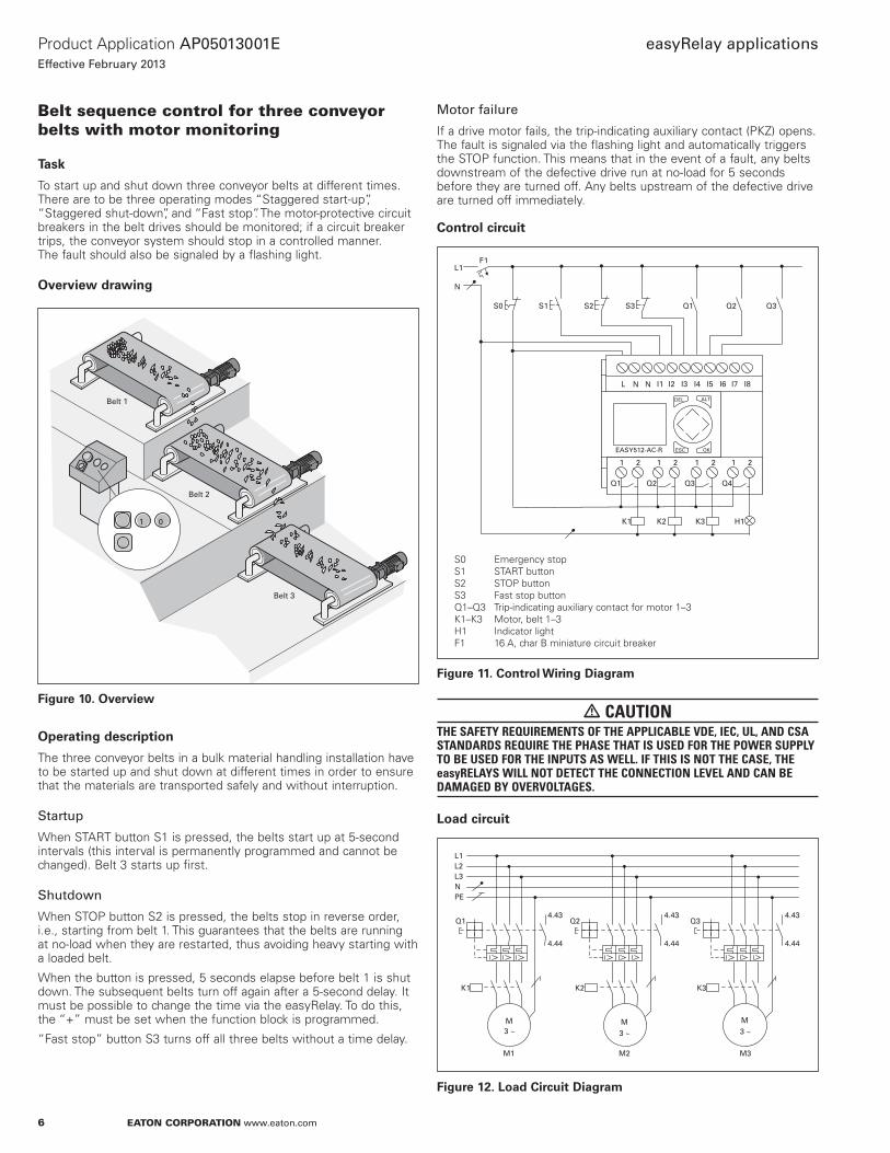
To start up and shut down three conveyor belts at different times. There are to be three operating modes “Staggered start-up”, “Staggered shut-down”, and “Fast stop”. The motor-protective circuit breakers in the belt drives should be monitored; if a circuit breaker trips, the conveyor system should stop in a controlled manner. The fault should also be signaled by a flashing light.
Overview drawing
1 0
Belt 1
Belt 2
Belt 3
Figure 10. Overview
Operating description
The three conveyor belts in a bulk material handling installation have to be started up and shut down at different times in order to ensure that the materials are transported safely and without interruption.
Startup
When START button S1 is pressed, the belts start up at 5-second intervals (this interval is permanently programmed and cannot be changed). Belt 3 starts up first.
Shutdown
When STOP button S2 is pressed, the belts stop in reverse order, i.e., starting from belt 1. This guarantees that the belts are running at no-load when they are restarted, thus avoiding heavy starting with a loaded belt.
When the button is pressed, 5 seconds elapse before belt 1 is shut down. The subsequent belts turn off again after a 5-second delay. It must be possible to change the time via the easyRelay. To do this, the “+” must be set when the function block is programmed.
“Fast stop” button S3 turns off all three belts without a time delay.
Motor failure
If a drive motor fails, the trip-indicating auxiliary contact (PKZ) opens. The fault is signaled via the flashing light and automatically triggers the STOP function. This means that in the event of a fault, any belts downstream of the defective drive run at no-load for 5 seconds before they are turned off. Any belts upstream of the defective drive are turned off immediately.
Control circuit
F1L1
N
S1S0 S2 S3 Q1 Q2 Q3
ALTDEL
ESC OKEASY512-AC-R
I1 I2 I3 I4 I5 I6 I7 I8L N N
Q1 Q2 Q3 Q4
1 2 1 2 1 2 1 2
K3K1 K2 H1
S0 Emergency stopS1 START buttonS2 STOP buttonS3 Fast stop buttonQ1–Q3 Trip-indicating auxiliary contact for motor 1–3K1–K3 Motor, belt 1–3H1 Indicator lightF1 16 A, char B miniature circuit breaker
Figure 11. Control Wiring Diagram
� CAUTIONTHE SAFETY REQUIREMENTS OF THE APPLICABLE VDE, IEC, UL, AND CSA STANDARDS REQUIRE THE PHASE THAT IS USED FOR THE POWER SUPPLY TO BE USED FOR THE INPUTS AS WELL. IF THIS IS NOT THE CASE, THE easyRELAYS WILL NOT DETECT THE CONNECTION LEVEL AND CAN BE DAMAGED BY OVERVOLTAGES.
Load circuit
L1
NPE
L2L3
Q1
K1
4.43
4.44
Q2
K2
4.43
4.44
Q3
K3
4.43
4.44
M3 ~
M3 ~
M3 ~
M3M2M1
Figure 12. Load Circuit Diagram

7
Product Application AP05013001E
Effective February 2013
easyRelay applications
EATON CORPORATION www.eaton.com
List of operands
I1 Input, START button
I2 Input, STOP button
I3 Input, Fast stop button
I4 Input, trip-indicating auxiliary contact for motor 1
I5 Input, trip-indicating auxiliary contact for motor 2
I6 Input, trip-indicating auxiliary contact for motor 3
M1 Marker relay, buffer memory, trip-indicating auxiliary contact, motor 1, 2, 3
M2 Marker relay, buffer memory, STOP
M3 Marker relay, buffer memory, START
Q1 Output, contactor in motor for belt 1
Q2 Output, contactor in motor for belt 2
Q3 Output, contactor in motor for belt 3
Q4 Output, indicator light
T1 Timing relay with 5-second ON delay —> Start belt 2
T2 Timing relay with 5-second ON delay —> Start belt 1
T3 Timing relay with 5-second OFF delay —> Stop belt 1
T4 Timing relay with 5-second OFF delay —> Stop belt 2
T5 Timing relay with 5-second OFF delay —> Stop belt 3
T6 Timing relay flashing for 1 second to indicate fault
Benefits
Implemented functions:2 x ON-delayed timing relays
2 x OFF-delayed timing relays
1 x flash/blink relay
2 x auxiliary contactors
Less wiring required
Takes up less space than conventional systems
Password function protects against unauthorized access
Examples
Customer: Program:
Date: Page:
Comment:
I
Belt control
1/4/13
Example 3
1
4 I 5 I 6
I 1 M 1
Q 3
T 1 M 1
Q 2
2
I 2
T
M
3
1
3
Q 1
M 1
Q 3S
TT 2
T 1T
M 3S
START button->motor for belt 3 on
Motor-protective circuit breaker 1, 2, 3 not tripped
START button pressed
Motor for belt 2 on
Motor for belt 1 on
OFF-delay for belt 1
ON-delay for belt 2
ON-delay for belt 1
STOP button pressed
Motor for belt 1 off
OFF-delay for belt 2
Q 2S
S Q 1
S M 2
TT 3
TT 4
QR 1
Q 3
MT 1
2
M 3
M
I
Figure 13. easyRelay Display Diagram

8
Product Application AP05013001E
Effective February 2013
easyRelay applications
EATON CORPORATION www.eaton.com
Customer: Program:
Date: Page:
Comment:
T
Belt control
1/4/13
Example 3
2
4 3
5
3
2
T 5
6
I 3
5
6
6
Q 2
QR 3
Motor for belt 2 off
OFF-delay for belt 3
A motor has failed
Motor for belt 3 off
Indicator light
T 5T
TT 6
Q 4
M 3
M
I 4
I
I
I
I
6I
I
T
Q
R
Figure 14. easyRelay Display Diagram
Customer: Program:
Date: Page:
Comment:
T
Belt control
1/4/13
Example 3
3
5 3
1
2
1
M 2 Reset buffer memory for STOP
Reset buffer memory for START
M
3I
M
3I
I
M
R
M 3R
Figure 15. easyRelay Display Diagram
TRG T
RES
TRG T
RES
TRG T
RES
: :: : :: 0 5S
X
1
0 0 0 5 0 0 0 5 0 0
+
2
+
3
+
S
X
S
X
Timing relays
TRG T
RES
TRG T
RES
TRG T
RES
: :: : :: 0 5S
X
4
0 0 0 5 0 0 0 1 0 0
+
5
+
6
+
S S
X
Timing relays
Customer: Program:
Date: Page:
Belt control
1/4/13
Example 3
4
Figure 16. easyRelay Display Parameters
9
Product Application AP05013001E
Effective February 2013
easyRelay applications
EATON CORPORATION www.eaton.com
Greenhouse temperature and
ventilation control
Task
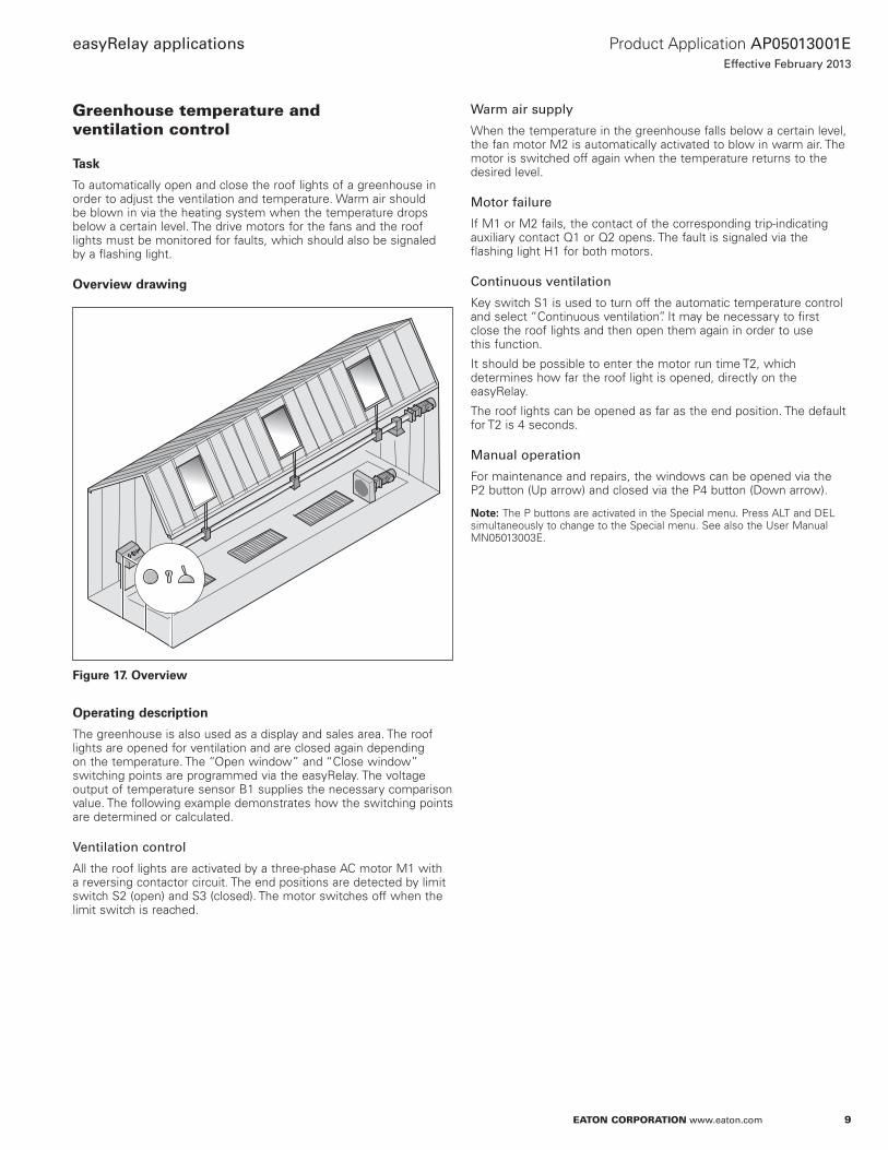
To automatically open and close the roof lights of a greenhouse in order to adjust the ventilation and temperature. Warm air should be blown in via the heating system when the temperature drops below a certain level. The drive motors for the fans and the roof lights must be monitored for faults, which should also be signaled by a flashing light.
Overview drawing
Figure 17. Overview
Operating description
The greenhouse is also used as a display and sales area. The roof lights are opened for ventilation and are closed again depending on the temperature. The “Open window” and “Close window” switching points are programmed via the easyRelay. The voltage output of temperature sensor B1 supplies the necessary comparison value. The following example demonstrates how the switching points are determined or calculated.
Ventilation control
All the roof lights are activated by a three-phase AC motor M1 with a reversing contactor circuit. The end positions are detected by limit switch S2 (open) and S3 (closed). The motor switches off when the limit switch is reached.
Warm air supply
When the temperature in the greenhouse falls below a certain level, the fan motor M2 is automatically activated to blow in warm air. The motor is switched off again when the temperature returns to the desired level.
Motor failure
If M1 or M2 fails, the contact of the corresponding trip-indicating auxiliary contact Q1 or Q2 opens. The fault is signaled via the flashing light H1 for both motors.
Continuous ventilation
Key switch S1 is used to turn off the automatic temperature control and select “Continuous ventilation”. It may be necessary to first close the roof lights and then open them again in order to use this function.
It should be possible to enter the motor run time T2, which determines how far the roof light is opened, directly on the easyRelay.
The roof lights can be opened as far as the end position. The default for T2 is 4 seconds.
Manual operation
For maintenance and repairs, the windows can be opened via the P2 button (Up arrow) and closed via the P4 button (Down arrow).
ote:N The P buttons are activated in the Special menu. Press ALT and DEL simultaneously to change to the Special menu. See also the User Manual MN05013003E.

10
Product Application AP05013001E
Effective February 2013
easyRelay applications
EATON CORPORATION www.eaton.com
Control circuit
H1
F1
G1
S0
0V+24V
L1
PEN
F2
S1 S3S2
K1
K1
K2
K2
K3
~
-
Q1 Q2
B1T
0-10V
ALTDEL
ESC OKEASY512-DC-R
I1 I2 I3 I4 I5 I6 I7 I824V 0V 0V
Q1 Q2 Q3 Q4
1 2 1 2 1 2 1 2
B1 Temperature sensorF1 16 A char. B miniature circuit breaker F2 Miniature circuit breaker (optional)G1 Power supply unit 230 Vac/24 VdcH1 Motor fault indicator light K1 Contactor for Open window drive motorK2 Contactor for Close window drive motorK3 Contactor for fan motorQ1 Window drive motor tripping indicatorQ2 Fan motor tripping indicatorS0 Emergency stopS1 Key switchS2 Open limit switchS3 Closed limit switch
Figure 18. Control Wiring Diagram
ote:N The electrical interlock may be omitted when using a reversing contactor combination with a mechanical interlock.
Load circuit
K2
L1
NPE
L2L3
Q1
K1
4.43
4.44
Q2
K3
4.43
4.44
M3 ~
M
3 ~
M2M1
Figure 19. Load Circuit Diagram
Sample switching points
Temperature sensor measuring range: –35°C to +55°C
Output signal from temperature sensor: 0 to 10 Vdc
Selected switching point—Open: 25°C
Selected switching point—Close: 23°C
Selected switching point—Heat: 20°C
General formula for the comparison value:
UL = Upper limit of measured valueLL = Lower limit of measured value
10VUL + LL
×= (Switchpoint + LL)
Set point value for Open comparator:
10V55ºC + 35ºC
× =(25ºC + 35ºC) 6, 4V
Set point value for Close comparator:
10V55ºC + 35ºC
× =(23ºC + 35ºC) 6, 4V
Set point value for Heat comparator:
10V55ºC + 35ºC
× =(20ºC + 35ºC) 6, 1V
A switching range (± 0.1V) must be defined for each comparison value to avoid having to repeatedly turn ON and OFF when the comparison value is reached.
This gives the following switching points in the comparator blocks:
Open window ON = 6.8V OFF = 6.6V
Close window ON = 6.3V OFF = 6.5V
Heat ON = 6.0V OFF = 6.2V
List of operands
A1 Comparator, Open window ON
A2 Comparator, Open window OFF
A3 Comparator, Close window ON
A4 Comparator, Close window OFF
A5 Comparator, Heat ON
A6 Comparator, Heat OFF
I1 Input, key switch for continuous ventilation
I2 Input, Open limit switch
I3 Input, Closed limit switch
I4 Input, window drive motor trip-indicating auxiliary contact. Input, fan motor trip-indicating auxiliary contact
I8 Input, comparative voltage of temperature sensor
11
Product Application AP05013001E
Effective February 2013
easyRelay applications
EATON CORPORATION www.eaton.com
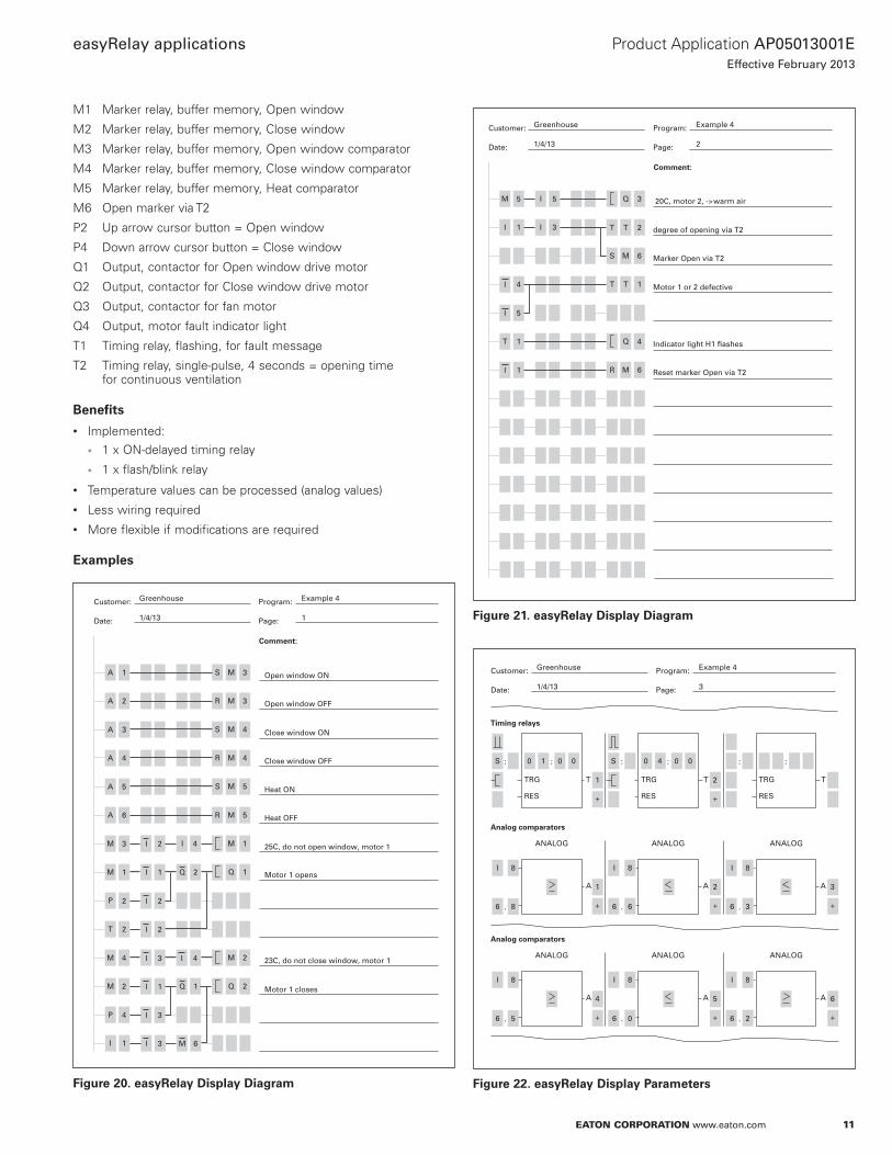
M1 Marker relay, buffer memory, Open window
M2 Marker relay, buffer memory, Close window
M3 Marker relay, buffer memory, Open window comparator
M4 Marker relay, buffer memory, Close window comparator
M5 Marker relay, buffer memory, Heat comparator
M6 Open marker via T2
P2 Up arrow cursor button = Open window
P4 Down arrow cursor button = Close window
Q1 Output, contactor for Open window drive motor
Q2 Output, contactor for Close window drive motor
Q3 Output, contactor for fan motor
Q4 Output, motor fault indicator light
T1 Timing relay, flashing, for fault message
T2 Timing relay, single-pulse, 4 seconds = opening time for continuous ventilation
Benefits
Implemented:1 x ON-delayed timing relay
1 x flash/blink relay
Temperature values can be processed (analog values)
Less wiring required
More flexible if modifications are required
Examples
Customer: Program:
Date: Page:
Comment:
A
Greenhouse
1/4/13
Example 4
1
1
A 2
A 3
A 4
A 5
A 6
3
M
P
M
1
T 2
M
M
4
2
P 4
I 1
MS 3
MR 5
M 4R
Open window ON
Open window OFF
Close window OFF
Heat OFF
Motor 1 opens
Close window ON
Heat ON
25C, do not open window, motor 1
Motor 1 closes
23C, do not close window, motor 1
MR 3
MS 4
M 5S
MI 4 1
M 2
Q 1
Q 2
2
I 22
I
1 2I
I 2
I 3
I 3
I 3 M 6
I 1
I 4
Q
1Q
Figure 20. easyRelay Display Diagram
Customer: Program:
Date: Page:
Comment:
M
Greenhouse
1/4/13
Example 4
2
5 I 5
I 1 I 3
4
I 5
T 1
1
Q 3
T 2T
4
T 1T
M 6S
degree of opening via T2
20C, motor 2, ->warm air
Marker Open via T2
Reset marker Open via T2
Motor 1 or 2 defective
Indicator light H1 flashes
R M 6
Q
I
I
Figure 21. easyRelay Display Diagram
ANALOG ANALOG ANALOG
TRG T
RES
TRG T
RES
TRG T
RES
::: 0 1S
1
0 0 : : :0 4 0 0
+
2
+
S
Timing relays
A A
I 8
.6 8
I 8
.6 6
I 8
.6 3
1
+
2
+
A 3
+
Analog comparators
ANALOG ANALOG ANALOG
A A
I 8
.6 5
I 8
.6 0
I 8
.6 2
4
+
5
+
A 6
+
Analog comparators
Customer: Program:
Date: Page:
Greenhouse
1/4/13
Example 4
3
Figure 22. easyRelay Display Parameters

12
Product Application AP05013001E
Effective February 2013
easyRelay applications
EATON CORPORATION www.eaton.com
Lighting control in a production room
Task
To automatically turn on the lighting fixtures in a production room during production hours. The lights should turn on and off gradually in response to changes in the daylight level. It must be possible to turn the switch for the individual lighting stages on and off manually at any time. Faults in the lighting system should be signaled by a flashing light.
Overview drawing
Figure 23. Overview
Operating description
Three light fixtures, each with 12 fluorescent lights, are suspended from a busbar system. The lighting is on from 6:00 a.m. to 5:30 p.m. Monday through Friday and is varied according to the daylight level. The switch-on times and the ON duration must be variable to suit requirements.
Lighting stages
The use of three different switching stages guarantees the necessary brightness, saves energy, and places a uniform load on the mains supply.
Connection to the busbar system
Phase 1: Every 1st, 4th, 7th, and 10th neon light. Activated via contactor K1. Enabled via daylight control switch B1.
Phase 2: Every 2nd, 5th, 8th, and 11th neon light. Activated via contactor K2. Enabled via daylight control switch B2.
Phase 3: Every 3rd, 6th, 9th, and 12th neon light. Activated via contactor K3. Enabled via daylight control switch B3.
Lighting stages
Stage 0: All the lights are off.
Stage 1: Every third light is on. Contact B1 is closed.
Stage 2: Every third light is off. Contacts B1 and B2 are closed.
Stage 3: All the lights are on. Contacts B1, B2, and B3 are closed.
Manual operation
It must be possible to switch the individual lighting stages at light switches S1 through S3.
Use of the manual function is signaled by indicator lights H1 through H3.
Failure of a busbar
The busbars are protected via miniature circuit breakers Q1 through Q3 and are monitored by trip indicating auxiliary contacts. Faults are signaled in the form of a group alarm via flashing indicator light H4.
ote:N If the daylight control switches already have an ON-delay or OFF-delay, these times should be set as low as possible (of the order of 1 second). Alternatively, the ON-delayed timers T1 through T6 programmed in the easyRelay (default value 60 seconds) can be changed to obtain the required overall delay.

13
Product Application AP05013001E
Effective February 2013
easyRelay applications
EATON CORPORATION www.eaton.com
Control circuit
H3H2H1H4
F1L1
N
S1 S2 S3B1 B2 B3 Q1
Q2
Q3
K1 K2 K3
S1 S2 S3
ALTDEL
ESC OKEASY512-AC-RC
I1 I2 I3 I4 I5 I6 I7 I8L N N
Q1 Q2 Q3 Q4
1 2 1 2 1 2 1 2
B1–B3 Contact, daylight control switch 1–3F1 16 A, char B miniature circuit breaker H1–H3 Indicator light, stage 1–3H4 Fault indicator lightK1–K3 Contactor, lighting stage 1–3Q1–Q3 Miniature circuit breaker 1–3S1–S3 Light switch, stage 1–3
Figure 24. Control Wiring Diagram
� CAUTIONTHE SAFETY REQUIREMENTS OF THE APPLICABLE VDE, IEC, UL, AND CSA STANDARDS REQUIRE THE PHASE THAT IS USED FOR THE POWER SUPPLY TO BE USED FOR THE INPUTS AS WELL. IF THIS IS NOT THE CASE, THE easyRELAYS WILL NOT DETECT THE CONNECTION LEVEL AND CAN BE DAMAGED BY OVERVOLTAGES.
Load circuit
L1
NPE
L2L3
1L1
N PE
1L21L3
2L1
N PE
2L22L3
3L1
N PE
3L23L3
Q1
K1
4.43
4.44
Q2
K2
4.43
4.44
Q3
K3
4.43
4.44
Figure 25. Load Circuit Diagram
Switching points of the daylight control switch
LightDark
On <- B3-> Off
On <- B2-> Off
On <- B1-> Off
Figure 26. Switching Points of the Daylight Programmable Switch
List of operands
I1 Input, light switch, stage 1
I2 Input, light switch, stage 2
I3 Input, light switch, stage 3
I4 Input, contact of daylight control switch 1
I5 Input, contact of daylight control switch 2
I6 Input, contact of daylight control switch 3
I7 Input, circuit breaker messages
M1 Marker relay, buffer memory, stage 1
M2 Marker relay, buffer memory, stage 2
M3 Marker relay, buffer memory, stage 3
Q1 Output, contactor for stage 1
Q2 Output, contactor for stage 2
Q3 Output, contactor for stage 3
Q4 Output, fault indicator light
T1 Timing relay with 60-second ON delay —> Stage 1 ON
T2 Timing relay with 60-second ON delay —> Stage 1 OFF
T3 Timing relay with 60-second ON delay —> Stage 2 ON
T4 Timing relay with 60-second ON delay —> Stage 2 OFF
T5 Timing relay with 60-second ON delay —> Stage 3 ON
T6 Timing relay with 60-second ON delay —> Stage OFF
T7 Timing relay, flashing for 1 second to indicate fault
Benefits
Implemented functions:1 x flash/blink relay
1 x single-channel time switch with weekly and daily programs
Functional overall solution
Less wiring required
Takes up less space than conventional systems
14
Product Application AP05013001E
Effective February 2013
easyRelay applications
EATON CORPORATION www.eaton.com
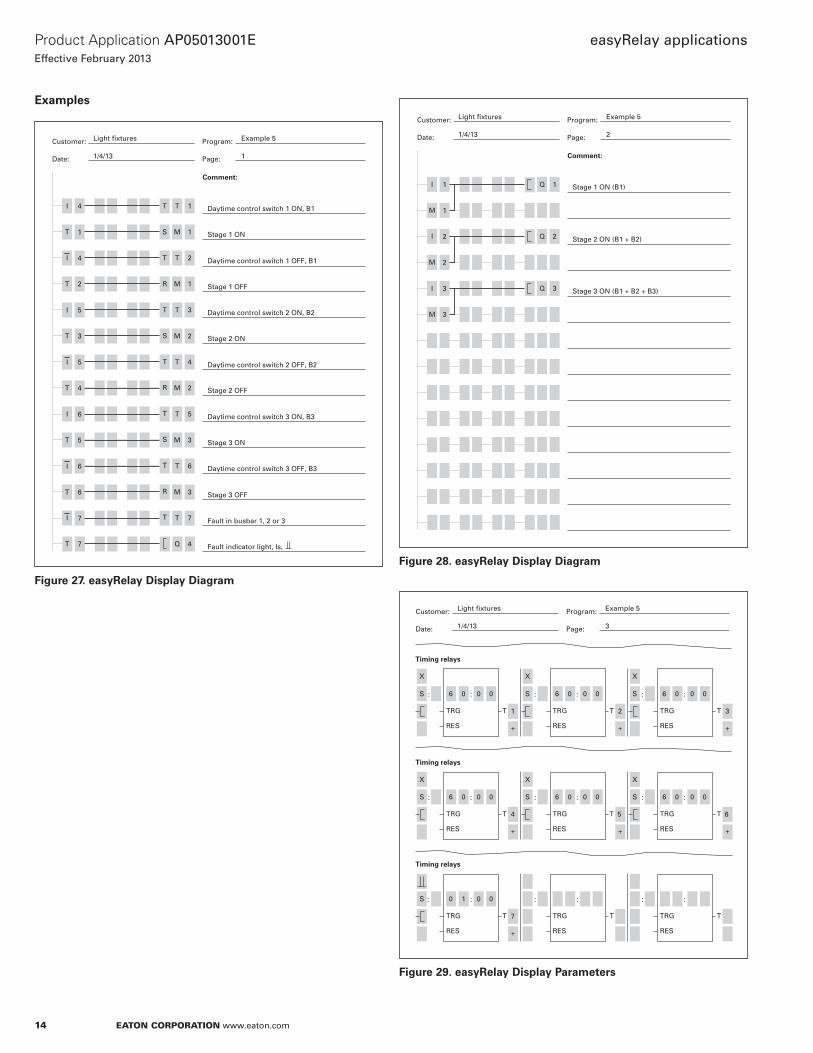
Examples
Customer: Program:
Date: Page:
Comment:
I
Light fixtures
1/4/13
Example 5
1
4
T 1
4
T 2
I 5
T
I
3
5
T 4
T
T
5
6
6
7
T 7
TT 1
M 2
M 1R
Daytime control switch 1 ON, B1
Stage 1 ON
Stage 1 OFF
Stage 2 ON
Stage 2 OFF
Daytime control switch 1 OFF, B1
Stage 3 ON
Daytime control switch 2 ON, B2
Daytime control switch 2 OFF, B2
Daytime control switch 3 ON, B3
Stage 3 OFF
Fault in busbar 1, 2 or 3
Fault indicator light, Is,
Daytime control switch 3 OFF, B3
MS 1
TT 2
T 3T
S
T T 4
R
T
M 2
T 5
S M 3
T
R
T 6
M 3
T T 7
Q 4
6
I
I
I
I
Figure 27. easyRelay Display Diagram
Customer: Program:
Date: Page:
Comment:
I
Light fixtures
1/4/13
Example 5
2
1
M 1
2
M 2
I 3
M 3
Q 1 Stage 1 ON (B1)
Stage 2 ON (B1 + B2)
Stage 3 ON (B1 + B2 + B3)
Q 2
Q 3
I
Figure 28. easyRelay Display Diagram
TRG T
RES
TRG T
RES
TRG T
RES
::: 6 0S
1
0 0 : : :6 0 0 0 6 0 0 0
+
2
+
3
+
S
X
S
X
Timing relays
Timing relays
TRG T
RES
TRG T
RES
TRG T
RES
::: 6 0S
4
0 0 : : :6 0 0 0 6 0 0 0
+
5
+
6
+
S
Timing relays
TRG T
RES
TRG T
RES
TRG T
RES
::: 0 1S
7
0 0 : : :
+
Customer: Program:
Date: Page:
Light fixtures
1/4/13
Example 5
3
X
X
S
XX
Figure 29. easyRelay Display Parameters

15
Product Application AP05013001E
Effective February 2013
easyRelay applications
EATON CORPORATION www.eaton.com
Booster pumps
Task
Two pumps provide the water supply for an installation. Their operation is to be monitored. The two pumps are to be operated alternately to prevent excessive wear. The operating status and the faults within the installation are to be signaled by two indicator lights. It must be possible to select the pressure-related switching points for activating the pumps as required.
Overview drawing
Figure 30. Overview
Operating description
Pumping operation
The pumping station provides the water supply for an installation. It must also ensure that the pressure does not fall below a specified minimum level. There are two booster pumps—P1 and P2. If the pressure is too low, one of the pumps is activated via pressure sensor B1. To ensure that the two pumps are subject to equal use and wear, they are run alternately for 48-hour periods. Two indicator lights, H1 and H2, signal which of the two pumps is in use. If the easyRelay is disconnected from the power supply, the operating hours count will start again, and pump 1 will be activated first.
To enable the pumps to change over after a shorter or longer operating period, counters C1 and C2 should be set to new comparison values using the following formula:
Desired changeover time in hours x 60 = comparison value.
Default: 48 hours x 60 = 2880.
Faults
Electrical failure of a pump motor is detected by the trip-indicating auxiliary contacts for the motor-protective circuit breaker Q1 and Q2. The pump that is still in working order will be activated. If one of the pumps is mechanically defective, the resulting drop in pressure will be detected, and the other pump will be activated after time T4 has elapsed. Both fault types are signaled by the flashing indicator light H1 or H2. When both pumps are electrically defective, indicator lights H1 and H2 will flash simultaneously.
Low pressure
The system is monitored for low pressure, which is signaled by indicator lights H1 and H2 that flash alternately after time T5 has elapsed. It must be possible to set the low pressure limit on the easyRelay.
Acknowledgement
All fault messages are retained until they have been acknowledged by pressing the S3 button.
Maintenance
It must be possible to directly switch pump P1 using key switch S1 and pump P2 using key switch S2.
16
Product Application AP05013001E
Effective February 2013
easyRelay applications
EATON CORPORATION www.eaton.com
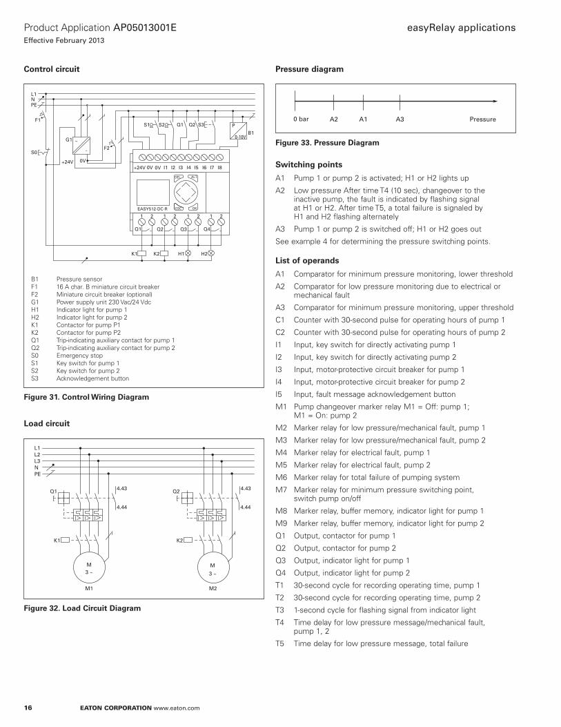
Control circuit
H2H1
F1
G1
S0
0V+24V
L1
PEN
F2
S1 S3S2
K1 K2
~
-
Q2Q1
B1P
0-10V
ALTDEL
ESC OKEASY512-DC-R
I1 I2 I3 I4 I5 I6 I7 I8+24V 0V 0V
Q1 Q2 Q3 Q4
1 2 1 2 1 2 1 2
B1 Pressure sensorF1 16 A char. B miniature circuit breaker F2 Miniature circuit breaker (optional)G1 Power supply unit 230 Vac/24 VdcH1 Indicator light for pump 1H2 Indicator light for pump 2K1 Contactor for pump P1K2 Contactor for pump P2Q1 Trip-indicating auxiliary contact for pump 1Q2 Trip-indicating auxiliary contact for pump 2S0 Emergency stopS1 Key switch for pump 1S2 Key switch for pump 2S3 Acknowledgement button
Figure 31. Control Wiring Diagram
Load circuit
L1
NPE
L2L3
Q1
K1
4.43
4.44
Q2
K2
4.43
4.44
M3 ~
M
3 ~
M2M1
Figure 32. Load Circuit Diagram
Pressure diagram
Pressure0 bar A1A2 A3
Figure 33. Pressure Diagram
Switching points
A1 Pump 1 or pump 2 is activated; H1 or H2 lights up
A2 Low pressure After time T4 (10 sec), changeover to the inactive pump, the fault is indicated by flashing signal at H1 or H2. After time T5, a total failure is signaled by H1 and H2 flashing alternately
A3 Pump 1 or pump 2 is switched off; H1 or H2 goes out
See example 4 for determining the pressure switching points.
List of operands
A1 Comparator for minimum pressure monitoring, lower threshold
A2 Comparator for low pressure monitoring due to electrical or mechanical fault
A3 Comparator for minimum pressure monitoring, upper threshold
C1 Counter with 30-second pulse for operating hours of pump 1
C2 Counter with 30-second pulse for operating hours of pump 2
I1 Input, key switch for directly activating pump 1
I2 Input, key switch for directly activating pump 2
I3 Input, motor-protective circuit breaker for pump 1
I4 Input, motor-protective circuit breaker for pump 2
I5 Input, fault message acknowledgement button
M1 Pump changeover marker relay M1 = Off: pump 1; M1 = On: pump 2
M2 Marker relay for low pressure/mechanical fault, pump 1
M3 Marker relay for low pressure/mechanical fault, pump 2
M4 Marker relay for electrical fault, pump 1
M5 Marker relay for electrical fault, pump 2
M6 Marker relay for total failure of pumping system
M7 Marker relay for minimum pressure switching point, switch pump on/off
M8 Marker relay, buffer memory, indicator light for pump 1
M9 Marker relay, buffer memory, indicator light for pump 2
Q1 Output, contactor for pump 1
Q2 Output, contactor for pump 2
Q3 Output, indicator light for pump 1
Q4 Output, indicator light for pump 2
T1 30-second cycle for recording operating time, pump 1
T2 30-second cycle for recording operating time, pump 2
T3 1-second cycle for flashing signal from indicator light
T4 Time delay for low pressure message/mechanical fault, pump 1, 2
T5 Time delay for low pressure message, total failure

17
Product Application AP05013001E
Effective February 2013
easyRelay applications
EATON CORPORATION www.eaton.com
Benefits
Implemented functions:1 x flash/blink relay
2 x ON-delayed timing relays
1 x operating hour counters
Processing of pressure values (analog values)
Variable switching points and operating hour changeover
Less wiring required
Takes up less space than conventional systems
Examples
Customer: Program:
Date: Page:
Comment:
A
Pumping station
1/4/13
Example 6
1
1
A 3
I 1
M 7 M 1 I 3
M 1 I 4
I 2
1Q
T
C 1
Q 2
T 2
MS 7
MR 7
M 9
Q 1
Lower threshold for minimum pressure
Upper threshold for minimum pressure
Pump 1 active
Pump 2 ON indicator light
Reset counter 2
Pump 1 ON indicator light
Change over to pump 2
Pump 2 active
Pump 1 run time clock
Pulse counter 1-48 hours
Reset counter 1
Pulse counter 2-48 hours
Change over to pump 1
Pump 2 run time clock
Q 2
TT 1
TT
R
2
CR
C
2
M 8
C 1
S M 1
C 1
C C 2
C 2 R M 1
1
Figure 34. easyRelay Display Diagram
Customer: Program:
Date: Page:
Comment:
Pumping station
1/4/13
Example 6
2
I 3
A 2
5T
T
M 2
M 2
M 4
M 8
TT 3
MS
S
R
1
T 4
M 1
Clock for flashing signal from indicator light
Electrical fault in pump 1
Electrical fault in pump 2
Low pressure monitoring
Low pressure signal, total failure
Active pump 2
Active pump 2
Active pump 1
Mechanical fault in pump 1
H1 flashes
Pump 1 in use
Total failure ->Lights flash alternately
Fault in pump 1 -> Indicator light
I 4
I 5
M 5
TT 5
Q 3
MS
S
6
M 4
M 2
S M 1
M 6 T 3
4 Q 1
I 4
T 3 6
M
M
3
S
T
Figure 35. easyRelay Display Diagram
Customer: Program:
Date: Page:
Comment:
Pumping station
1/4/13
Example 6
3
M 3 I 3
M 6
5I
MS22Q4T 3
MR 1
Mechanical fault in pump 2
Active pump 1
H2 flashes
Total failure -> Lights flash alternately
Acknowledge fault messages
Fault in pump 2 -> Indicator light
Pump 2 in use
M 5
T 3
MR 2
M 6
MR
R
3
Q 4T 3M 3
M 9
M 4
R
R
M 5
M
M
6
Figure 36. easyRelay Display Diagram
18
Product Application AP05013001E
Effective February 2013
easyRelay applications
EATON CORPORATION www.eaton.com
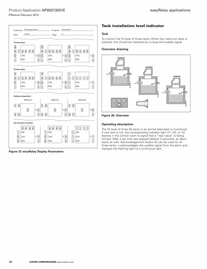
CNT
DIR
C
RES
CNT
DIR
C
RES
CNT
DIR
C
RES
ANALOG ANALOG ANALOG
TRG T
RES
TRG T
RES
TRG T
RES
::: 3 0S
1
0 0 : : :3 0 0 0 0 1 0 0
+
2
+
3
+
S S
Timing relays
A A
I 8
.2 9
I 8
.2 0
I 8
.3 1
1
+
2
+
1
+
2
+
A 3
+
Analog comparators
Up and down counters
TRG T
RES
TRG T
RES
TRG T
RES
::: 1 0S
4
0 0
2 8 8 0 2 8 8 0
: : :2 5 0 0
+
5
+
S
X
Timing relays
Customer: Program:
Date: Page:
Pumping station
1/4/13
Example 6
4
X
Figure 37. easyRelay Display Parameters
Tank installation level indicator
Task
To monitor the fill level of three tanks. When the maximum level is reached, this should be indicated by a visual and audible signal.
Overview drawing
Figure 38. Overview
Operating description
The fill level of three fat tanks in an animal feed plant is monitored. If one tank is full, the corresponding indicator light H1, H2, or H3 flashes in the control room to signal that a “new value” is being formed. After a set time has elapsed (default 3 seconds), an alarm starts as well. Acknowledgement button S4 can be used for all three tanks; it acknowledges the audible signal from the alarm and changes the flashing light to a continuous light.

19
Product Application AP05013001E
Effective February 2013
easyRelay applications
EATON CORPORATION www.eaton.com
Control circuit
H4
F1L1
N
S1 S2 S3 S4
H2 H3H1
ALTDEL
ESC OKEASY512-AC-R
I1 I2 I3 I4 I5 I6 I7 I8L N N
Q1 Q2 Q3 Q4
1 2 1 2 1 2 1 2
F1 16 A, char. B miniature circuit breaker H1 Indicator light for tank 1H2 Indicator light for tank 2H3 Indicator light for tank 3H4 AlarmS1 Level indicator for tank 1S2 Level indicator for tank 2S3 Level indicator for tank 3S4 Acknowledgement button
Figure 39. Control Wiring Diagram
� CAUTIONTHE SAFETY REQUIREMENTS OF THE APPLICABLE VDE, IEC, UL, AND CSA STANDARDS REQUIRE THE PHASE THAT IS USED FOR THE POWER SUPPLY TO BE USED FOR THE INPUTS AS WELL. IF THIS IS NOT THE CASE, THE easyRELAYS WILL NOT DETECT THE CONNECTION LEVEL AND CAN BE DAMAGED BY OVERVOLTAGES.
List of operands
I1 Input, float switch for tank 1
I2 Input, float switch for tank 2
I3 Input, float switch for tank 3
I4 Input, acknowledgement button
M1 Marker relay, acknowledged full message from tank 1
M2 Marker relay, acknowledged full message from tank 2
M3 Marker relay, acknowledged full message from tank 3
Q1 Output, indicator light for tank 1
Q2 Output, indicator light for tank 2
Q3 Output, indicator light for tank 3
Q4 Output, Alarm
T1 Timing relay with 3-second ON delay —> delay after tank 1 full message
T2 Timing relay with 3-second ON delay —> delay after tank 2 full message
T3 Timing relay with 3-second ON delay —> delay after tank 3 full message
T4 Single-pulse timing relay —> Alarm ON set pulse
T5 Single-pulse timing relay —> Alarm ON set pulse
T6 Single-pulse timing relay —> Alarm ON set pulse
T7 Timing relay flashing for 0.5 second —> New value signal
Benefits
Implemented functions:3 x ON-delayed timing relays
1 x flash/blink relay
3 x auxiliary contactors
Less wiring required
Takes up less space than conventional systems
20
Product Application AP05013001E
Effective February 2013
easyRelay applications
EATON CORPORATION www.eaton.com
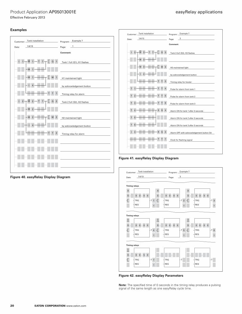
Examples
Customer: Program:
Date: Page:
Comment:
I
Tank installation
1/4/13
Example 7
1
1 1
I 4
I 2 2
M
1M
7T
7T
M 2
Q 1
Q 2
Tank 1 full (S1), H1 flashes
by acknowledgement button
Tank 2 full (S2), H2 flashes
H2 maintained light
H1 maintained light
Timing relay for alarm
Timing relay for alarm
by acknowledgement button
M
2M
1M
T 1T
T 2T
M 1
M 2
I 4
Figure 40. easyRelay Display Diagram
Customer: Program:
Date: Page:
Comment:
I
Tank installation
1/4/13
Example 7
2
3
I 4
T
T
T
I
1
2
T 3
T 5
T 6
4
Q 3M 3
M 3
M 3
T 7 Tank 3 full (S3), H3 flashes
by acknowledgement button
Pulse for alarm from tank 1
Pulse for alarm from tank 3
H3 maintained light
Alarm ON for tank 2 after 3 seconds
Timing relay for hooter
Pulse for alarm from tank 2
Alarm ON for tank 1 after 3 seconds
Alarm OFF with acknowledgement button S4
Clock for flashing signal
Alarm ON for tank 3 after 3 seconds
T 3T
T 4T
T 5T
T 6T
T 7T
M 3
QS
R
4
Q 4
4
Figure 41. easyRelay Display Diagram
TRG T
RES
TRG T
RES
TRG T
RES
::: 0 3S
1
0 0 : : :0 3 0 0 0 3 0 0
+
2
+
3
+
S S
Timing relays
TRG T
RES
TRG T
RES
TRG T
RES
::: 0 0S
4
0 0 : : :0 0 0 0 0 0 0 0
+
5
+
6
+
S S
Timing relays
Customer: Program:
Date: Page:
Tank installation
1/4/13
Example 7
3
X X X
TRG T
RES
TRG T
RES
TRG T
RES
::: 0 0S
7
5 0 : : :
+
Timing relays
Figure 42. easyRelay Display Parameters
ote:N The specified time of 0 seconds in the timing relay produces a pulsing signal of the same length as one easyRelay cycle time.

21
Product Application AP05013001E
Effective February 2013
easyRelay applications
EATON CORPORATION www.eaton.com
Access monitoring for a parking garage
Task
To monitor the occupancy of a company parking garage. Cars can enter the garage provided that there are still some spaces available. Access is controlled by a barrier system. The occupancy of the garage is signaled by a “Full/Empty” display.
Overview drawing
Figure 43. Overview
Operating description
Entry and exit
Access to the garage is monitored by a swipe card reader. If the card is valid, contact S3 is closed briefly. When a vehicle leaves the garage, contact S2 is closed via an induction loop embedded in the ground. A display panel with the message “Full” or “Spaces free” at the point of entry should indicate whether there are still parking spaces available. If voltage is present at signal input K2, the display panel should read “Full”, otherwise it should read “Spaces free”. The barrier opens when a voltage pulse is applied to K1 for 2 seconds, and it closes automatically when a vehicle has passed through or after a set time has elapsed.
Counting the vehicles
Incoming and outgoing vehicles should be counted by the easyRelay. The maximum number of vehicles that can be parked can be set on the easyRelay. Vehicles may enter if there are parking spaces available. The counter can be reset to zero via the key switch S5 in order to establish a baseline.
Manual operation
The garage attendant should be able to open the barrier at any time using button S4, regardless of whether the garage is full or not.
Faults
A fault in the barrier system, which is signaled via make contact S1, is displayed by flashing indicator light H1 in the garage attendant’s booth.
Maintenance
The barrier can be opened by pressing the P2 function button (Up arrow) on the easyRelay.
Control circuit
F1L1
N
S1 S2 S3 S4 S5
H1K1 K2
ALTDEL
ESC OKEASY512-AC-R
I1 I2 I3 I4 I5 I6 I7 I8L N N
Q1 Q2 Q3 Q4
1 2 1 2 1 2 1 2
F1 16 A, char. B miniature circuit breaker H1 Fault flashing indicator light K1 Barrier driving circuitK2 Display panel driving circuitS1 Barrier fault indicatorS2 Contact for induction loopS3 Contact for swipe card readerS4 Open barrier button S5 Reset counter key switch
Figure 44. Control Wiring Diagram
� CAUTIONTHE SAFETY REQUIREMENTS OF THE APPLICABLE VDE, IEC, UL, AND CSA STANDARDS REQUIRE THE PHASE THAT IS USED FOR THE POWER SUPPLY TO BE USED FOR THE INPUTS AS WELL. IF THIS IS NOT THE CASE, THE easyRELAYS WILL NOT DETECT THE CONNECTION LEVEL AND CAN BE DAMAGED BY OVERVOLTAGES.

22
Product Application AP05013001E
Effective February 2013
easyRelay applications
EATON CORPORATION www.eaton.com
List of operands
C1 Vehicle counter
I1 Input, fault barrier
I2 Input, contact for induction loop
I3 Input, contact for swipe card reader
I4 Input, open barrier button
I5 Input, reset counter key switch
P2 Up arrow cursor button = open barrier
Q1 Output, open barrier
Q2 Output, display panel
Q3 Output, fault indicator light
T1 Single 2-second single-pulse timing relay = open barrier pulse
T2 Timing relay with 1-second flashing cycle = barrier fault flashing message
Benefits
Implemented functions:1 x flash/blink relay
1 x up/down counter with reset function
1 x ON-delayed timing relay
Compact system
Easy program duplication with program transfer
Examples
Customer: Program:
Date: Page:
Comment:
I
Parking garage
1/4/13
Example 8
1
3
I 2
I 4
P 2
T 1
I
I
I
T
5
2
I 2
C 1
I 1
2
TT 1C 1 Open pulse from swipe card reader
Induction loop
Maintenance
Counter reset by S5
Car exiting = Counter - 1
Attendant
Full
Barrier opens
Counting direction DOWN
Car entering = Counter + 1
Flashing signal in attendant’s booth
Fault at barrier
C 1
Q 1
C 1R
C 1D
T 2T
CC 1
Q 3
3
Q 2
Figure 45. easyRelay Display Diagram
CNT
DIR
C
RES
CNT
DIR
C
RES
CNT
DIR
C
RES
TRG T
RES
TRG T
RES
TRG T
RES
::: 0 2S
1
0 0 : : :0 1 0 0
+
2
+
S
Timing relays
Customer: Program:
Date: Page:
Parking garage
1/4/13
Example 8
2
0 0 3 0
1
+
Up and down counters
Figure 46. easyRelay Display Parameters
23
Product Application AP05013001E
Effective February 2013
easyRelay applications
EATON CORPORATION www.eaton.com
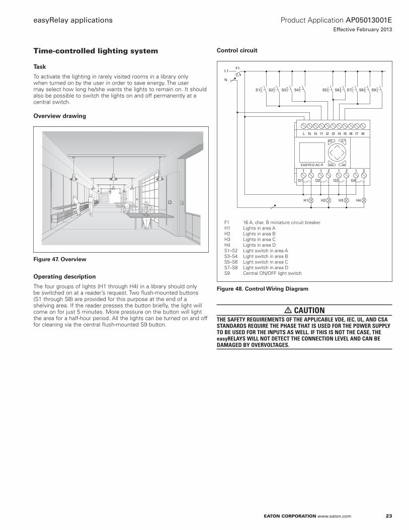
Time-controlled lighting system
Task
To activate the lighting in rarely visited rooms in a library only when turned on by the user in order to save energy. The user may select how long he/she wants the lights to remain on. It should also be possible to switch the lights on and off permanently at a central switch.
Overview drawing
Figure 47. Overview
Operating description
The four groups of lights (H1 through H4) in a library should only be switched on at a reader’s request. Two flush-mounted buttons (S1 through S8) are provided for this purpose at the end of a shelving area. If the reader presses the button briefly, the light will come on for just 5 minutes. More pressure on the button will light the area for a half-hour period. All the lights can be turned on and off for cleaning via the central flush-mounted S9 button.
Control circuit
H1 H2 H3 H4
F1L1
N
S1 S2 S3 S4 S5 S6 S7 S8 S9
ALTDEL
ESC OKEASY512-AC-R
I1 I2 I3 I4 I5 I6 I7 I8L N N
Q1 Q2 Q3 Q4
1 2 1 2 1 2 1 2
F1 16 A, char. B miniature circuit breaker H1 Lights in area AH2 Lights in area BH3 Lights in area CH4 Lights in area DS1–S2 Light switch in area AS3–S4 Light switch in area BS5–S6 Light switch in area CS7–S8 Light switch in area DS9 Central ON/OFF light switch
Figure 48. Control Wiring Diagram
� CAUTIONTHE SAFETY REQUIREMENTS OF THE APPLICABLE VDE, IEC, UL, AND CSA STANDARDS REQUIRE THE PHASE THAT IS USED FOR THE POWER SUPPLY TO BE USED FOR THE INPUTS AS WELL. IF THIS IS NOT THE CASE, THE easyRELAYS WILL NOT DETECT THE CONNECTION LEVEL AND CAN BE DAMAGED BY OVERVOLTAGES.

24
Product Application AP05013001E
Effective February 2013
easyRelay applications
EATON CORPORATION www.eaton.com
List of operands
C1 Counter, ON duration 5 min., area A
C2 Counter, ON duration 30 min., area A
C3 Counter, ON duration 5 min., area B
C4 Counter, ON duration 30 min., area B
C5 Counter, ON duration 5 min., area C
C6 Counter, ON duration 30 min., area C
C7 Counter, ON duration 5 min., area D
C8 Counter, ON duration 30 min., area D
I1 Input, light switch S1/S2, area A
I2 Input, light switch S3/S4, area B
I3 Input, light switch S5/S6, area C
I4 Input, light switch S7/S8, area D
I5 Input, central ON/OFF light switch
M1 Marker relay, buffer memory, light in area A ON for 5 min.
M2 Marker relay, buffer memory, light in area A ON for 30 min.
M3 Marker relay, buffer memory, light in area B ON for 5 min.
M4 Marker relay, buffer memory, light in area B ON for 30 min.
M5 Marker relay, buffer memory, light in area C ON for 5 min.
M6 Marker relay, buffer memory, light in area C ON for 30 min.
M7 Marker relay, buffer memory, light in area D ON for 5 min.
M8 Marker relay, buffer memory, light in area D ON for 30 min.
M9 Marker relay, buffer memory, light ON/OFF at central switch
Q1 Output relay, light area A
Q2 Output relay, light area B
Q3 Output relay, light area C
Q4 Output relay, light area D
T1 Timing relay with 2-second ON delay = short/long ON duration, area A
T2 Timing relay with 2-second ON delay = short/long ON duration, area B
T3 Timing relay with 2-second ON delay = short/long ON duration, area C
T4 Timing relay with 2-second ON delay = short/long ON duration, area D
T8 Flashing 20-second cycle for short/long ON duration
Benefits
Implemented functions:12 x ON-delayed timing relays
1 x impulse changeover relay
Less wiring required
Takes up less space than conventional systems
Examples
Customer: Program:
Date: Page:
Comment:
Library lighting
1/4/13
Example 9
1
Q 1
M
M
C
I
2
1
M 2
C 2
M 9
1
T 8
Central light ON/OFF switch
Switch S1/S2 short pressure
Switch S1/S2 long pressure
Counter 2 Duration: 30 minutes
Light at output 1 ON 30 min.
Counter 1 Duration: 5 minutes
5 min.
Reset counter 1 and 2
via central ON switch
M 2
C 1C
C 2C
C 1R
I 5
I 1
M 1
T 1
Q 1
T 8
T 8
M 1
M 2
I 1
M 9
TT
T
1
M 1
Q 1
R C 2
1
Figure 49. easyRelay Display Diagram
Customer: Program:
Date: Page:
Comment:
Library lighting
1/4/13
Example 9
2
Q 2
Q 2
M
C
M
M
4
3
C 4
I 2
I 3
5
T 2
Switch S3/S4 short pressure
Switch S3/S4 long pressure
Counter 4 Duration: 30 minutes
Light at output 2 ON 30 min.
Counter 3 Duration: 5 minutes
5 min.
Switch S5/S6 short pressure
Reset counter 3 and 4
via central ON switch
C 3C
C 4C
Q 2
C 3R
R
T 3T
M 3
I 2
I 2
M 4
T 8
T 2
T 8
M 3
M 4
Q 3
M 3
M 3
T
M 4
C 4
M 5
9
Figure 50. easyRelay Display Diagram

25
Product Application AP05013001E
Effective February 2013
easyRelay applications
EATON CORPORATION www.eaton.com
Customer: Program:
Date: Page:
Comment:
Library lighting
1/4/13
Example 9
3
T 8
Q 3
M
C
C
I
M
6
9
I 3
M 7
I 4
8
Switch S5/S6 long pressure
Counter 6 Duration: 30 minutes
Light at output 3 ON 30 min.
Counter 5 Duration: 5 minutes
Counter 7 Duration: 5 minutes
5 min.
Switch S7/S8 long pressure
Switch S7/S8 short pressure
Reset counter 5 and 6
via central ON switch
C 5C
C 6C
Q 3
C 6R
T 4T
C 5R
M 6
I 3 T 3
M 5
M 6
M 5
T 8
M 6
Q 4
Q 4
T 4
5
M 6
M 7
M 8
M 7 T 8 CC 7
4
Figure 51. easyRelay Display Diagram
Customer: Program:
Date: Page:
Comment:
Library lighting
1/4/13
Example 9
4
M 7C
C
C 8
Light at output 4 ON 30 min.
Counter 8 Duration: 30 minutes
5 min.
Reset counter 7 and 8
C 7R
C 8R
7
M 8 T 8
8
I 4
M 8
Q 4
C
Figure 52. easyRelay Display Diagram
TRG T
RES
TRG T
RES
TRG T
RES
::: 0 2S
1
0 0 : : :0 2 0 0 0 2 0 0
+
2
+
3
+
S S
Timing relays
TRG T
RES
TRG T
RES
TRG T
RES
::: 0 2S
4
0 0 : : :3 0 0 0
+
8
+
S
Timing relays
Customer: Program:
Date: Page:
Library lighting
1/4/13
Example 9
5
X X X
X
Figure 53. easyRelay Display Parameters
CNT
DIR
C
RES
CNT
DIR
C
RES
CNT
DIR
C
RES
Customer: Program:
Date: Page:
Library lighting
1/4/13
Example 9
6
0 0 0 5
1
+
2
+
3
+
5
+
6
+
0 0 3 0 0 0 0 5
Up and down counters
CNT
DIR
C
RES
CNT
DIR
C
RES
CNT
DIR
C
RES
0 0 3 0 0 0 0 5 0 0 3 0
4
+
Up and down counters
CNT
DIR
C
RES
CNT
DIR
C
RES
CNT
DIR
C
RES
0 0 0 5 0 0 3 0
7
+
8
+
Up and down counters
Figure 54. easyRelay Display Parameters

26
Product Application AP05013001E
Effective February 2013
easyRelay applications
EATON CORPORATION www.eaton.com
Refrigeration control system
Task
To turn the compressors of the refrigeration system in a hotel on and off in response to the system pressure. The system pressure is supplied by the easyRelay via analog input I8. The value at I8 is compared with set point values and the switching points are derived from the comparison value.
Overview drawing
Figure 55. Overview
Operating description
The pressure of the refrigeration system is compared with set point values. Timers are connected upstream of the outputs so that pressure fluctuations in the system do not cause the compressors to turn on immediately.
Set point values
Output Q1: Set: A1 ≥ 1.8 bar Time T1 = 5 sec Reset: A5 ≤ 1.7 bar
Output Q2: Set: A2 ≥ 2.0 bar Time T2 = 20 sec Reset: A6 ≤ 1.9 bar
Output Q3: Set: A3 ≥ 2.2 bar Time T3 = 20 sec Reset: A7 ≤ 2.1 bar
Output Q4: Set: A4 ≥ 2.4 bar Time T4 = 20 sec Reset: A8 ≤ 2.3 bar
Control circuit
F1
G1
S0
0V+24V
L1
PEN
F2
S1
K1 K2 K3 K4
~
-
B1P
0-10V
ALTDEL
ESC OKEASY512-DC-R
I1 I2 I3 I4 I5 I6 I7 I824V 0V 0V
Q1 Q2 Q3 Q4
1 2 1 2 1 2 1 2
B1 Pressure sensorF1 16 A, char. B miniature circuit breaker F2 Miniature circuit breaker (optional)G1 Power supply unit 230 Vac/24 VdcK1–K4 Compressor 1–4S0 Emergency stopS1 ON/OFF key switch
Figure 56. Control Wiring Diagram
Load circuit
L1
NPE
L2L3
Q1
K1
M3 ~
M1
Q24.43
4.44
4.43
4.44
4.43
4.44
4.43
4.44
K2
M3 ~
M2
Q3
K3
M3 ~
M3
Q4
K4
M3 ~
M4
Figure 57. Load Circuit Diagram
List of operands
A1 Comparator, motor 1 ON after T1 has elapsed
A2 Comparator, motor 2 ON after T2 has elapsed
A3 Comparator, motor 3 ON after T3 has elapsed
A4 Comparator, motor 4 ON after T4 has elapsed
A5 Comparator, motor 1 OFF
A6 Comparator, motor 2 OFF
A7 Comparator, motor 3 OFF
A8 Comparator, motor 4 OFFI1 Input, system ON/OFF
I8 Input, comparison voltage from pressure sensor
27
Product Application AP05013001E
Effective February 2013
easyRelay applications
EATON CORPORATION www.eaton.com
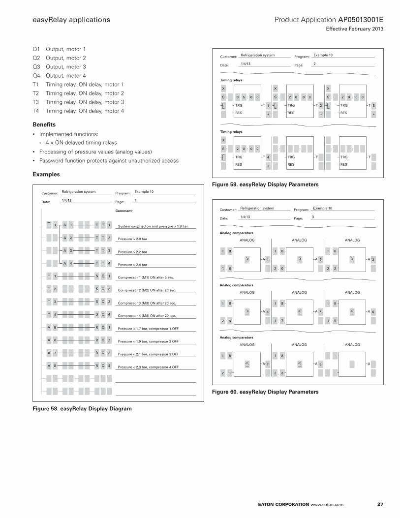
Q1 Output, motor 1
Q2 Output, motor 2
Q3 Output, motor 3
Q4 Output, motor 4
T1 Timing relay, ON delay, motor 1
T2 Timing relay, ON delay, motor 2
T3 Timing relay, ON delay, motor 3
T4 Timing relay, ON delay, motor 4
Benefits
Implemented functions:4 x ON-delayed timing relays
Processing of pressure values (analog values)
Password function protects against unauthorized access
Examples
Customer: Program:
Date: Page:
Comment:
I
Refrigeration system
1/4/13
Example 10
1
1
A 4
T
T
T
A
1
2
T 3
A 6
A 7
8
T 1A 1
A 2
A 3
System switched on and pressure > 1.8 bar
Pressure > 2.4 bar
Compressor 2 (M2) ON after 20 sec.
Compressor 4 (M4) ON after 20 sec.
Pressure > 2.2 bar
Pressure > 2.0 bar
Pressure < 1.9 bar, compressor 2 OFF
Compressor 1 (M1) ON after 5 sec.
Compressor 3 (M3) ON after 20 sec.
Pressure < 1.7 bar, compressor 1 OFF
Pressure < 2.3 bar, compressor 4 OFF
Pressure < 2.1 bar, compressor 3 OFF
Q 1S
Q 2S
Q 3S
Q 4S
QR
R
1
QR 2
QR 3
Q 4
4
A 5
T
T 2T
T 3T
T 4T
Figure 58. easyRelay Display Diagram
TRG T
RES
TRG T
RES
TRG T
RES
::: 0 5S
1
0 0 : : :2 0 0 0 2 0 0 0
+
2
+
3
+
S S
Timing relays
TRG T
RES
TRG T
RES
TRG T
RES
::: 2 0S
4
0 0 : : :
+
Timing relays
Customer: Program:
Date: Page:
Refrigeration system
1/4/13
Example 10
2
X X X
X
Figure 59. easyRelay Display Parameters
ANALOG ANALOG ANALOG
A A
I 8
.1 8
I 8
.2 0
I 8
.2 2
1 2 A 3
Analog comparators
Customer: Program:
Date: Page:
Refrigeration system
1/4/13 3
Example 10
ANALOG ANALOG ANALOG
A A
I 8
.2 4
I 8
.1 7
I 8
.1 9
4 5 A 6
Analog comparators
ANALOG ANALOG ANALOG
A A
I 8
.2 1
I 8
.2 3
7 8 A
Analog comparators
Figure 60. easyRelay Display Parameters
28
Product Application AP05013001E
Effective February 2013
easyRelay applications
EATON CORPORATION www.eaton.com
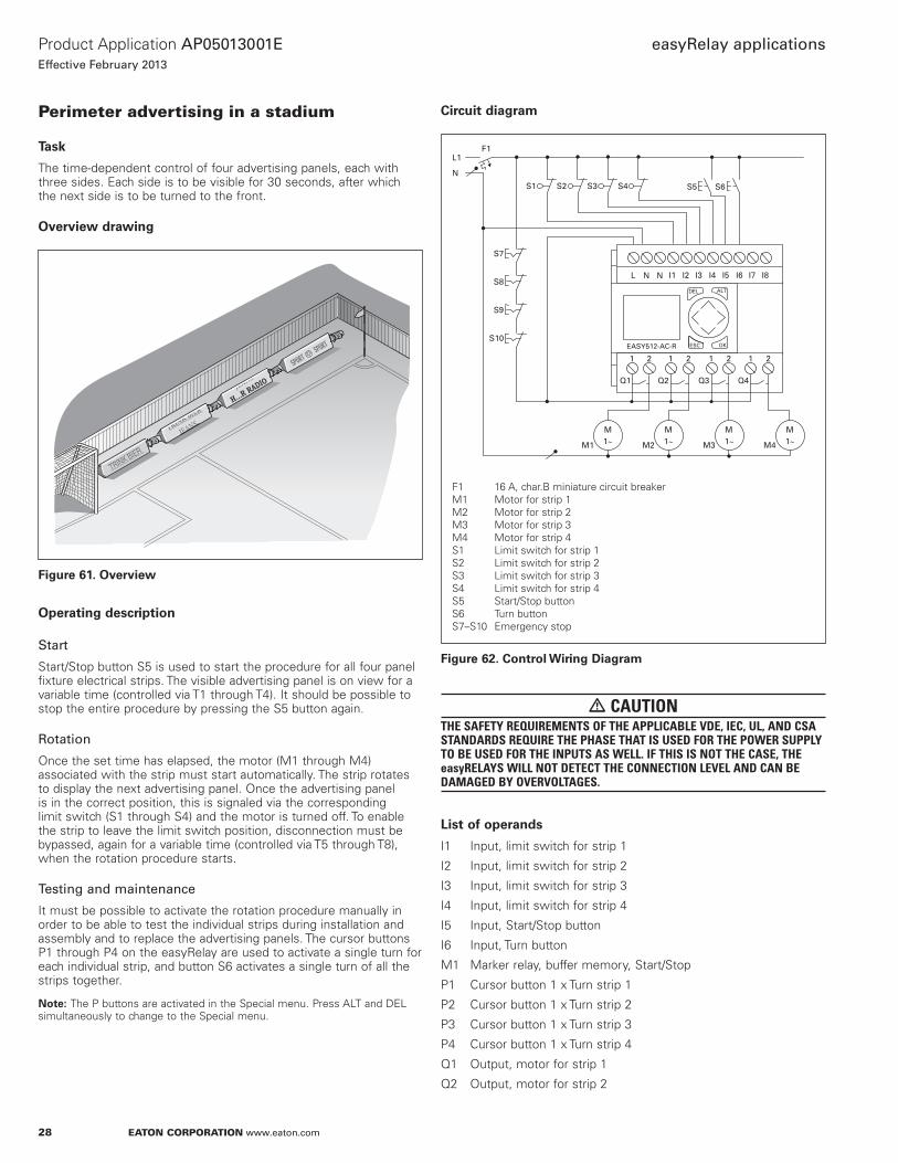
Perimeter advertising in a stadium
Task
The time-dependent control of four advertising panels, each with three sides. Each side is to be visible for 30 seconds, after which the next side is to be turned to the front.
Overview drawing
Figure 61. Overview
Operating description
Start
Start/Stop button S5 is used to start the procedure for all four panel fixture electrical strips. The visible advertising panel is on view for a variable time (controlled via T1 through T4). It should be possible to stop the entire procedure by pressing the S5 button again.
Rotation
Once the set time has elapsed, the motor (M1 through M4) associated with the strip must start automatically. The strip rotates to display the next advertising panel. Once the advertising panel is in the correct position, this is signaled via the corresponding limit switch (S1 through S4) and the motor is turned off. To enable the strip to leave the limit switch position, disconnection must be bypassed, again for a variable time (controlled via T5 through T8), when the rotation procedure starts.
Testing and maintenance
It must be possible to activate the rotation procedure manually in order to be able to test the individual strips during installation and assembly and to replace the advertising panels. The cursor buttons P1 through P4 on the easyRelay are used to activate a single turn for each individual strip, and button S6 activates a single turn of all the strips together.
ote:N The P buttons are activated in the Special menu. Press ALT and DEL simultaneously to change to the Special menu.
Circuit diagram
F1L1
N
S10
S1 S2 S5 S6
S9
S8
S7
S3 S4
M
M1 M2 M3 M41~M1~
M1~
M1~
ALTDEL
ESC OKEASY512-AC-R
I1 I2 I3 I4 I5 I6 I7 I8L N N
Q1 Q2 Q3 Q4
1 2 1 2 1 2 1 2
F1 16 A, char.B miniature circuit breaker M1 Motor for strip 1M2 Motor for strip 2M3 Motor for strip 3M4 Motor for strip 4S1 Limit switch for strip 1S2 Limit switch for strip 2S3 Limit switch for strip 3S4 Limit switch for strip 4S5 Start/Stop buttonS6 Turn buttonS7–S10 Emergency stop
Figure 62. Control Wiring Diagram
� CAUTIONTHE SAFETY REQUIREMENTS OF THE APPLICABLE VDE, IEC, UL, AND CSA STANDARDS REQUIRE THE PHASE THAT IS USED FOR THE POWER SUPPLY TO BE USED FOR THE INPUTS AS WELL. IF THIS IS NOT THE CASE, THE easyRELAYS WILL NOT DETECT THE CONNECTION LEVEL AND CAN BE DAMAGED BY OVERVOLTAGES.
List of operands
I1 Input, limit switch for strip 1
I2 Input, limit switch for strip 2
I3 Input, limit switch for strip 3
I4 Input, limit switch for strip 4
I5 Input, Start/Stop button
I6 Input, Turn button
M1 Marker relay, buffer memory, Start/Stop
P1 Cursor button 1 x Turn strip 1
P2 Cursor button 1 x Turn strip 2
P3 Cursor button 1 x Turn strip 3
P4 Cursor button 1 x Turn strip 4
Q1 Output, motor for strip 1
Q2 Output, motor for strip 2

29
Product Application AP05013001E
Effective February 2013
easyRelay applications
EATON CORPORATION www.eaton.com
Q3 Output, motor for strip 3
Q4 Output, motor for strip 4
T1 Timing relay with 30-second ON delay => Advert viewing time, strip 1
T2 Timing relay with 30-second ON delay => Advert viewing time, strip 2
T3 Timing relay with 30-second ON delay => Advert viewing time, strip 3
T4 Timing relay with 30-second ON delay => Advert viewing time, strip 4
T5 Single 1-second pulse timing relay => Block limit switch for starting strip 1
T6 Single 1-second pulse timing relay => Block limit switch for starting strip 2
T7 Single 1-second pulse timing relay => Block limit switch for starting strip 3
T8 Single 1-second pulse timing relay => Block limit switch for starting strip 4
Benefits
Implemented functions:8 x ON-delayed timing relays
1 x impulse changeover relay
Less wiring required
Takes up less space than conventional systems
Dwell-time of each strip can be individually selected
Examples
Customer: Program:
Date: Page:
Comment:
I
Stadium perimeter advertising
1/4/13
Example 11
1
5
T
P
I
I
1
1
I 6
T 2
P 2
6
2
M 1
M 1 Q 1 TT 1
TT 2
TT 3
Start/Stop turning
Start turning strip 1
Time for strip 1
Time for strip 2
Time for strip 3
Time for strip 4
Stop turning strip 2
Bypass disconnection of strip 1
Stop turning strip 1
Stop turning strip 2
Bypass disconnection of strip 2
Q 2
Q 3
Q 4
T 6
T 5
I
T 4T
Q 1S
Q 2S
T 5T
T 6T
QR 1
R Q 2
1
Figure 63. easyRelay Display Diagram
Customer: Program:
Date: Page:
Comment:
T
Stadium perimeter advertising
1/4/13
Example 11
2
3
P
I
4
T 4
6
I 4
I 6
Q 3
P 3 TT 7
QR 3
Start turning strip 3
Bypass disconnection of strip 4
Bypass disconnection of strip 3
Stop turning strip 3
Stop turning strip 4
Stop turning strip 4
3I
Q 4S
T 8T
T 8
T 7
QR 4
S
Figure 64. easyRelay Display Diagram
TRG T
RES
TRG T
RES
TRG T
RES
::: 3 0S
1
0 0 : : :3 0 0 0 3 0 0 0
+
2
+
3
+
S S
Timing relays
TRG T
RES
TRG T
RES
TRG T
RES
::: 3 0S
4
0 0 : : :0 1 0 0 0 1 0 0
+
5
+
6
+
S S
Timing relays
Customer: Program:
Date: Page:
Stadium perimeter advertising
1/4/13
Example 11
3
X
TRG T
RES
TRG T
RES
TRG T
RES
::: 0 1S
7
0 0 : : :0 1 0 0
+
8
+
S
Timing relays
X X X
Figure 65. easyRelay Display Parameters

30
Product Application AP05013001E
Effective February 2013
easyRelay applications
EATON CORPORATION www.eaton.com
Rolling door control
Task
To automatically control the roll-up security door at the entrance to an underground garage. The door should open on request and then close automatically after a set time. It should also be possible to close the door upon request. The door is locked at certain times of the day and certain days of the week. The limit switches and mechanical operation of the door should be constantly monitored.
Overview drawing
Figure 66. Overview
Operating description
Opening the rolling door
The rolling door can be opened from outside via a swipe card reader and/or key switch S6. Contact K1 closes briefly once the swipe card has been checked. It should be possible to lock the entrance at certain, variable times of the day and on certain days of the week ( 1); although it should always be possible to open the door using key switch S5.
The door must be opened using pull switch S7 in order to leave the garage.
Closing the rolling door
Once a car has driven into the garage, the driver can close the door manually via pull switch S7. If the driver does not use the pull switch, the door will automatically close after a set time (T3). The door can be opened and closed manually using the S4 and S5 buttons in the control room.
Security
Door closing should be indicated by a brief audible signal (H3). At the same time, red warning lights H1 and H2 light up at the entrance and the exit. If there is a person, a vehicle, or another object under the door while it is closing, the procedure will be stopped or prevented via the contact in the safety bar (K2) and/or the light barrier (K3). The door will either immediately open fully or will remain open. If the safety bar is triggered, there is an audible signal, and warning lights H1 and H2 light up.
The “Open door” function is disabled by the safety bar when the door is closed (limit switches actuated) in order to prevent break-in and vandalism.
The contact bar can be tested by triggering the alarm while the door is open.
Pressing the emergency stop button stops all movement of the door. Warning lights H1 and H2 will start to flash, and the audible signal will start.
If the door is closed, the alarm cannot be triggered via the emergency stop button. The “Open door” command must be given to start the flashing lights and the audible signal in order to indicate that the emergency stop button has been pressed.
Break contacts should be used for the emergency stop, safety bar, and limit switch functions. The emergency stop button and the safety bar must be wired as shown in Figure 67. This will guarantee that the opening and closing procedure during an emergency stop, and the door closing procedure when the safety bar is tripped, work independently of the electronic circuit.
The following standards must be observed:
DIN EN 60 335-1 (VDE 0700 part 1)
DIN 57 700-238 (VDE 0700 part 238)
German Workplace Directive ASR 11/1-5ZH1/494 and ZH1/580.1 Safety Rules
Faults
Defective limit switches S1 and S2 (door closed S1/door opened S2) and mechanical faults in the door must be detected. If a limit switch is not working correctly, the drive should be shut down after a variable time (T1 and T2) and warning lights H1 and H2 should start to flash. The message can be cleared by pressing and resetting emergency stop button S8. If emergency stop button S8 is pressed, the warning lights should light up and a continuous audible signal should start.
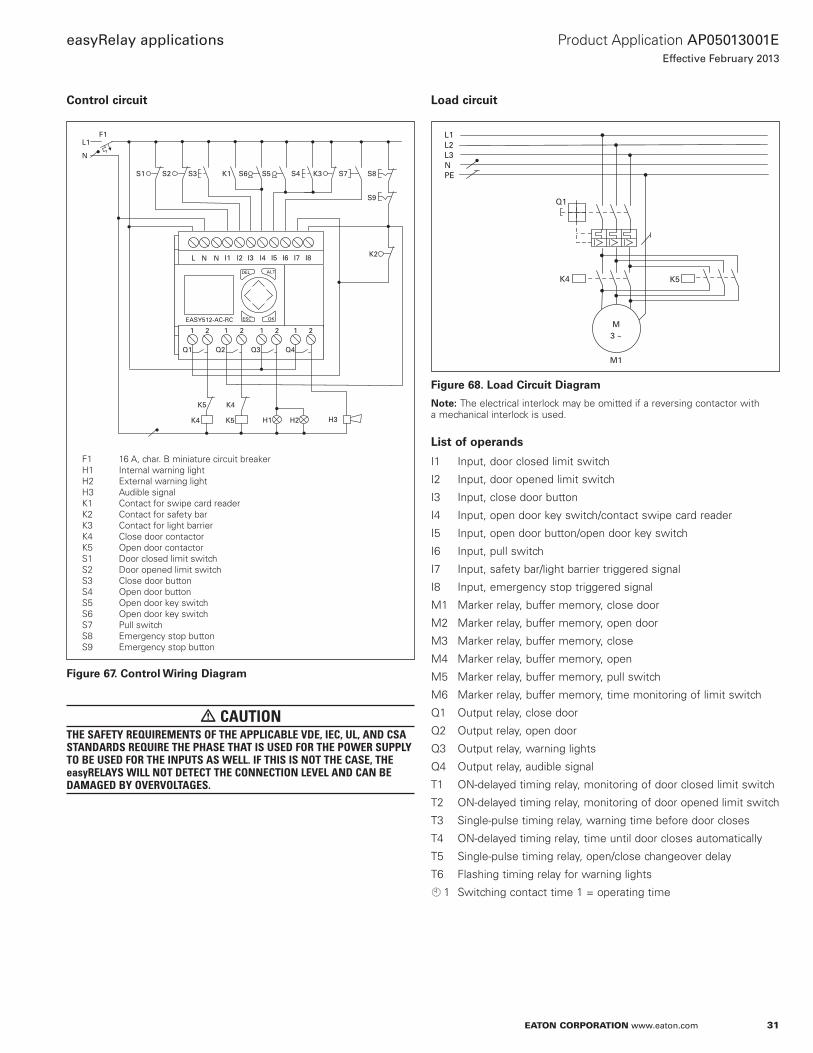
31
Product Application AP05013001E
Effective February 2013
easyRelay applications
EATON CORPORATION www.eaton.com
Control circuit
F1L1
N
S1 S2 S5 S4 K3
K2
S3 K1 S6 S7
S9
S8
K4
K4
K5
K5
H1 H3
ALTDEL
ESC OKEASY512-AC-RC
I1 I2 I3 I4 I5 I6 I7 I8L N N
Q1 Q2 Q3 Q4
1 2 1 2 1 2 1 2
H2
F1 16 A, char. B miniature circuit breakerH1 Internal warning light H2 External warning light H3 Audible signalK1 Contact for swipe card readerK2 Contact for safety barK3 Contact for light barrierK4 Close door contactorK5 Open door contactorS1 Door closed limit switchS2 Door opened limit switchS3 Close door buttonS4 Open door buttonS5 Open door key switchS6 Open door key switchS7 Pull switchS8 Emergency stop buttonS9 Emergency stop button
Figure 67. Control Wiring Diagram
� CAUTIONTHE SAFETY REQUIREMENTS OF THE APPLICABLE VDE, IEC, UL, AND CSA STANDARDS REQUIRE THE PHASE THAT IS USED FOR THE POWER SUPPLY TO BE USED FOR THE INPUTS AS WELL. IF THIS IS NOT THE CASE, THE easyRELAYS WILL NOT DETECT THE CONNECTION LEVEL AND CAN BE DAMAGED BY OVERVOLTAGES.
Load circuit
K5
L1
NPE
L2L3
Q1
K4
M3 ~
M1
Figure 68. Load Circuit Diagram
ote:N The electrical interlock may be omitted if a reversing contactor with a mechanical interlock is used.
List of operands
I1 Input, door closed limit switch
I2 Input, door opened limit switch
I3 Input, close door button
I4 Input, open door key switch/contact swipe card reader
I5 Input, open door button/open door key switch
I6 Input, pull switch
I7 Input, safety bar/light barrier triggered signal
I8 Input, emergency stop triggered signal
M1 Marker relay, buffer memory, close door
M2 Marker relay, buffer memory, open door
M3 Marker relay, buffer memory, close
M4 Marker relay, buffer memory, open
M5 Marker relay, buffer memory, pull switch
M6 Marker relay, buffer memory, time monitoring of limit switch
Q1 Output relay, close door
Q2 Output relay, open door
Q3 Output relay, warning lights
Q4 Output relay, audible signal
T1 ON-delayed timing relay, monitoring of door closed limit switch
T2 ON-delayed timing relay, monitoring of door opened limit switch
T3 Single-pulse timing relay, warning time before door closes
T4 ON-delayed timing relay, time until door closes automatically
T5 Single-pulse timing relay, open/close changeover delay
T6 Flashing timing relay for warning lights
1 Switching contact time 1 = operating time

32
Product Application AP05013001E
Effective February 2013
easyRelay applications
EATON CORPORATION www.eaton.com
Examples
Customer: Program:
Date: Page:
Comment:
M
Rolling door control
1/4/13
Lighting, example 12
1
3
I 1
8
M 4
M 6
M 4
2
8
M
M
6
I
I
3
6
I 6
T 4
M 2
M 1R
M 1S
S
MR
Door closing
End door closing via limit switch
End door closing via door opening
Door opening
End door closing via emergency stop
End door closing via emergency stop
End door closing via limit switch monitoring
End door closing via limit switch monitoring
End door opening via limit switch
End door closing via door opening
Door closing via S7
Door closing via Automatic
Door closing via S3
I
I
2I
2M 5M
I
2
M 3
3
Figure 69. easyRelay Display Diagram
Customer: Program:
Date: Page:
Comment:
I
Rolling door control
1/4/13
Example 12
2
4
I 5
I 6 I 1
I 6
7
I 6
3
M
M
M
M
2 M 3
M 1
2
M 4
M 5
Door opening via S6/K1
Door opening via S5
Pull switch
Automatic closing
Door opening via S7
Door opening via K2
Warning time before door closing
Open/close changeover delay
Door opening
Door closing
M 1 M 5
I 1
I
I
2I
I 8
TT 3
TT
T
4
T 5
Q 2
Q 1
5
T 5
T 5
T 3
M 4
I 7
1
1
Figure 70. easyRelay Display Diagram
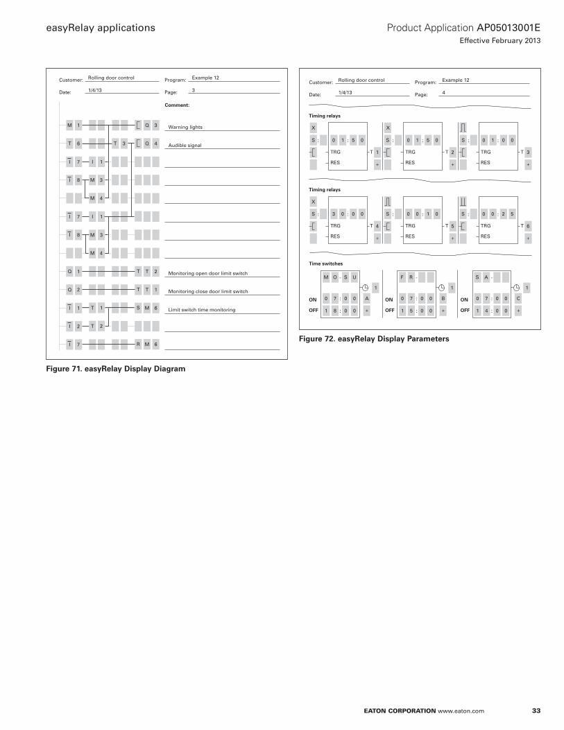
33
Product Application AP05013001E
Effective February 2013
easyRelay applications
EATON CORPORATION www.eaton.com
Customer: Program:
Date: Page:
Comment:
M
Rolling door control
1/4/13
Example 12
3
1
T 6 T 3
7 I 1
8
I 7 I 1
8
Q
M 4
Q 2
Q 3 Warning lights
Audible signal
Monitoring open door limit switch
Monitoring close door limit switch
Limit switch time monitoring
M 3
M 4
M
Q 4
T T 2
R M 6
T T 1
M 6
3
T
I
I
I
1I
2I
7I
1
T 2
1
S
Figure 71. easyRelay Display Diagram
TRG T
RES
TRG T
RES
TRG T
RES
::: 0 1S
1
5 0 : : :0 1 5 0 0 1 0 0
+
2
+
3
+
S S
Timing relays
TRG T
RES
TRG T
RES
TRG T
RES
::: 3 0S
4
0 0 : : :0 0 1 0 0 0 2 5
+
5
+
6
+
S S
Timing relays
Customer: Program:
Date: Page:
Rolling door control
1/4/13
Example 12
4
X
X X
-
:
:
ON
OFF
Time switches
M O F R S AS
1 1 1
U
0 7 0 0 A
1 8 0 0 +
:
:
0 7 0 0 B
1 5 0 0
:
:
0 7 0 0
1 4 0 0+
C
+
-
ON
OFF
-
ON
OFF
Figure 72. easyRelay Display Parameters

34
Product Application AP05013001E
Effective February 2013
easyRelay applications
EATON CORPORATION www.eaton.com

35
Product Application AP05013001E
Effective February 2013
easyRelay applications
EATON CORPORATION www.eaton.com

Eaton CorporationElectrical Sector1111 Superior AvenueCleveland, OH 44114 USAEaton.com
© 2013 Eaton CorporationAll Rights ReservedPrinted in USAPublication No. AP05013001E / Z13062March 2013
Eaton is a registered trademark of Eaton Corporation.
All other trademarks are property of their respective owners.
Product Application AP05013001E
Effective February 2013
easyRelay applications