EFFECTIVE CONTROL OF EARTHQUAKE RESPONSE USING TUNED ...home.iitk.ac.in/~vinaykg/Iset521.pdf · 54...
19
ISET Journal of Earthquake Technology, Paper No. 521, Vol. 49, No. 3-4, Sept.-Dec. 2012, pp. 53–71 EFFECTIVE CONTROL OF EARTHQUAKE RESPONSE USING TUNED LIQUID DAMPERS Mohan Murudi* and Pradipta Banerji** *Department of Structural Engineering Sardar Patel College of Engineering, Mumbai-400058 **Department of Civil Engineering Indian Institute of Technology Bombay, Mumbai-400076 ABSTRACT An earlier numerical study of a single-degree-of-freedom (SDOF) structure rigidly supporting a tuned liquid damper (TLD) and subjected to broad-band ground motions, has showed that a TLD has to be properly designed for effectively reducing the response of the structure. In this paper, a comprehensive study of the effects of various ground motion parameters on the ability of a TLD to reduce structural response for earthquake base motions is presented. It is shown that the frequency content and bandwidth of the ground motion do not significantly affect the effectiveness of the TLD. Since TLD is a nonlinear system, its effectiveness increases with an increase in the intensity of the ground motion. Furthermore, since TLD behaves as a viscous damper, it cannot reduce the response in the first few cycles of vibration. Therefore, TLD is more effective for the far-field ground motions, where the strong-motion phase and consequently the peak response of the structure occur after the first few cycles of vibration. KEYWORDS: Earthquake Response, Structural Control, Tuned Liquid Damper, Energy Dissipation, Nonlinear Damping INTRODUCTION A variety of passive control devices have been developed to control the vibrations of civil engineering structures due to dynamic loads, such as those due to wind, earthquakes, etc. The passive energy dissipation systems encompass a range of materials and devices for enhancing damping, stiffness and strength and can be used both for natural hazard mitigation in new structures and for the rehabilitation of ageing or deficient structures. In recent years, serious efforts have been undertaken to develop the concept of energy dissipation or supplemental damping into a workable technology and a number of these devices have been used throughout the world. Base isolation is one of the passive ways of controlling vibrations due to ground motions. The basic aim of base isolation is to shift the fundamental period of a structure away from the high-energy period of the ground motion, such that the structure is subjected to lower earthquake forces. A base isolation system causes a large displacement at the level of isolator, which needs to be accommodated or reduced by the supplemental means. The effectiveness of base isolation systems for controlling the seismic response of structures subjected to far-field ground motions has been well established. In recent years, there has been a considerable interest in studying the response of base-isolated buildings under the recorded near-fault earthquake motions (Jangid and Kelly, 2001). These ground motions contain one or more displacement pulses with peak velocities of the order of 0.5 m/s and durations in the range of 1–3 s. Such pulses have a large impact on the isolation systems with periods in this range and lead to large isolator displacements. Jangid and Kelly (2001) have studied the effectiveness of base isolation systems for near-fault motions. In their investigation, analytical studies of base-isolated structures were carried out. First, six pairs of near-fault motions oriented in directions parallel and normal to the fault were considered, and then the average of the response spectra of these earthquake records was obtained. This study has shown that, in addition to the pulse-type displacements, these motions contain significant energy at high frequencies and that the real and pseudo-velocity spectra are quite different. The second analysis modelled the response of a model of an isolated structure with a flexible superstructure to study the effect of isolation damping on the performance of different isolation systems under near-fault motions. The results have shown that there exists a value of isolation system damping for which the superstructure
Transcript of EFFECTIVE CONTROL OF EARTHQUAKE RESPONSE USING TUNED ...home.iitk.ac.in/~vinaykg/Iset521.pdf · 54...

ISET Journal of Earthquake Technology, Paper No. 521, Vol. 49, No. 3-4, Sept.-Dec. 2012, pp. 53–71
EFFECTIVE CONTROL OF EARTHQUAKE RESPONSE USING TUNED LIQUID DAMPERS
Mohan Murudi* and Pradipta Banerji** *Department of Structural Engineering
Sardar Patel College of Engineering, Mumbai-400058 **Department of Civil Engineering
Indian Institute of Technology Bombay, Mumbai-400076
ABSTRACT
An earlier numerical study of a single-degree-of-freedom (SDOF) structure rigidly supporting a tuned liquid damper (TLD) and subjected to broad-band ground motions, has showed that a TLD has to be properly designed for effectively reducing the response of the structure. In this paper, a comprehensive study of the effects of various ground motion parameters on the ability of a TLD to reduce structural response for earthquake base motions is presented. It is shown that the frequency content and bandwidth of the ground motion do not significantly affect the effectiveness of the TLD. Since TLD is a nonlinear system, its effectiveness increases with an increase in the intensity of the ground motion. Furthermore, since TLD behaves as a viscous damper, it cannot reduce the response in the first few cycles of vibration. Therefore, TLD is more effective for the far-field ground motions, where the strong-motion phase and consequently the peak response of the structure occur after the first few cycles of vibration.
KEYWORDS: Earthquake Response, Structural Control, Tuned Liquid Damper, Energy Dissipation, Nonlinear Damping
INTRODUCTION
A variety of passive control devices have been developed to control the vibrations of civil engineering structures due to dynamic loads, such as those due to wind, earthquakes, etc. The passive energy dissipation systems encompass a range of materials and devices for enhancing damping, stiffness and strength and can be used both for natural hazard mitigation in new structures and for the rehabilitation of ageing or deficient structures. In recent years, serious efforts have been undertaken to develop the concept of energy dissipation or supplemental damping into a workable technology and a number of these devices have been used throughout the world. Base isolation is one of the passive ways of controlling vibrations due to ground motions. The basic aim of base isolation is to shift the fundamental period of a structure away from the high-energy period of the ground motion, such that the structure is subjected to lower earthquake forces. A base isolation system causes a large displacement at the level of isolator, which needs to be accommodated or reduced by the supplemental means. The effectiveness of base isolation systems for controlling the seismic response of structures subjected to far-field ground motions has been well established. In recent years, there has been a considerable interest in studying the response of base-isolated buildings under the recorded near-fault earthquake motions (Jangid and Kelly, 2001). These ground motions contain one or more displacement pulses with peak velocities of the order of 0.5 m/s and durations in the range of 1–3 s. Such pulses have a large impact on the isolation systems with periods in this range and lead to large isolator displacements. Jangid and Kelly (2001) have studied the effectiveness of base isolation systems for near-fault motions. In their investigation, analytical studies of base-isolated structures were carried out. First, six pairs of near-fault motions oriented in directions parallel and normal to the fault were considered, and then the average of the response spectra of these earthquake records was obtained. This study has shown that, in addition to the pulse-type displacements, these motions contain significant energy at high frequencies and that the real and pseudo-velocity spectra are quite different. The second analysis modelled the response of a model of an isolated structure with a flexible superstructure to study the effect of isolation damping on the performance of different isolation systems under near-fault motions. The results have shown that there exists a value of isolation system damping for which the superstructure

54 Effective Control of Earthquake Response Using Tuned Liquid Dampers
acceleration for a given structural system attains a minimum value under the near-fault motions. Therefore, although increasing the bearing damping beyond a certain value may decrease the bearing displacement, it may also transmit higher accelerations into the superstructure. Finally, the behaviour of four isolation systems subjected to the normal component of each of the near-fault motions was studied and it has been seen that EDF-type isolation systems may be the optimum choice for the design of isolated structures in near-fault locations. Ye and Li (2009) have carried out a parametric study on the dynamic response of lead-rubber bearing (LRB) base-isolated structures under the near-fault pulse-like ground motions. Due to the limited number of real near-fault pulse-like records, for the convenience of the parametric study, artificially generated near-fault pulse-like ground motions were simulated by combining the real far-field ground motions with simple equivalent pulses that reflect the near-fault features. By using these artificially generated near-fault ground motions, different dynamic characteristics of LRB base-isolated structures under the near-fault pulse-like and far-field ground motions were studied. Moreover, the effects of different pulse types, near-fault ground motion parameters and dynamic properties of LRB isolation system on the maximum absolute acceleration of superstructure and maximum displacement at the isolation level were investigated. It has been concluded from this comprehensive study that the maximum absolute acceleration of superstructure and the maximum displacement at the isolation level of the LRB base-isolated structure subjected to near-fault pulse-like ground motions are much greater than those under the far-field ground motions. Further, the effective range of base isolation has been narrowed, and it has been seen that pulse type and pulse period have significant influences on the dynamic response of LRB base-isolated structures. Another class of passive devices that are commonly used consists of tuned mass dampers (TMDs) (Den Hartog, 1956; Warburton, 1982; Villaverde, 1994). A TMD consists of a secondary mass with properly tuned spring and damping elements such that the dynamic characteristics of the structure are changed and a frequency-dependent hysteresis is provided to increase damping in the structure. It has been well established that TMD is effective in reducing the wind-excited structural vibrations. Kamrani-Moghaddam et al. (2006) have investigated the performance of TMDs in the response reduction of structures for near-field and far-field earthquakes. The 3-, 9- and 20-story structures designed for the SAC phase II project were used in this study. First, time-history analyses were performed to calculate the response of each structure to the Chi-Chi, Kocaeili and Landers near-field and far-field earthquake records. The same procedure was followed for the models with a TMD duly attached. The results have shown that the performance of TMD in the 3-story structure was better for the far-field excitations, while in the 20-story structure, the performance was better for the near-field excitations. Pinelli et al. (2003) have studied and compared the feasibility and effectiveness of controlling the seismic vibrations of a structure through the installation of different combinations of TMDs. These include a single TMD tuned to one mode, multiple single TMDs controlling several modes (i.e., MTMDs), a battery of TMDs controlling one mode, also known as distributed tuned mass dampers (DTMDs), and several batteries controlling different modes, also known as multiple distributed tuned mass dampers (MDTMDs). The optimization criteria for each TMD combination were adopted from the literature, and modified as needed. Three public benchmark case studies were retrofitted with different combinations of TMDs and subjected to a series of earthquake ground motions with different durations and energy contents. The performance of each TMD scheme was evaluated based on the floor displacement and acceleration reduction as well as on the reduction of hysteretic energy dissipation in the structure. The influence on the performance of the TMDs of the nonlinear behavior of the structural members was also investigated. To evaluate the proposed control strategies under the benchmark evaluation study, two far-field and two near-field historical records were selected. From this study, the authors have concluded that under the far-field long-duration ground motions, both single-TMD and MTMD control methods can reduce the building response effectively. On comparing the results of the two methods, the MTMD control method has been found to give on average about 10% more acceleration reduction than the single-TMD control method. In the case of displacement reduction, both single-TMD and MTMD control methods have been found to perform similarly and larger mass ratios have resulted in bigger response reductions. However, the performance of both TMD and MTMD methods under the near-field earthquake motions has not been found to be significantly different. More recently, Matta (2011) has investigated three classical techniques and tested two new variants for designing a TMD on an SDOF structure under 338 NF records from the PEER NGA database,

ISET Journal of Earthquake Technology, September-December 2012 55
including 156 records with the forward-directivity features. Percentile response reduction spectra were introduced to statistically assess the TMD performance, and TMD robustness was verified through the Monte Carlo simulations. The methodology was extended to a variety of MDOF bending-type and shear-type frames and a case-study building structure recently constructed in central Italy. It has been concluded that, if properly designed and sufficiently massive, TMDs are effective and robust even under the excitation of pulse-like ground motions. The two newly proposed design techniques have been shown to generally outperform the classical ones. As discussed above, a base isolation system causes a large displacement at the level of isolator, especially when the system is subjected to the near-fault ground motions, and therefore this requires additional devices to control the isolator displacement. Taniguchi et al. (2008) have studied the effectiveness of TMD consisting of a mass-dashpot-spring subsystem that is attached to the isolated superstructure, analogous to a pendulum. Both the isolated superstructure and the TMD were modelled as linear single-degree-of-freedom oscillators. The optimal TMD parameters were determined by considering the response of the base-isolated structure, with and without the TMD, to a white-noise base acceleration time-history. Such an excitation is representative of the broad-band ground motions having a nearly constant intensity over a duration several times longer than the period of the base-isolated structure. It has been found that under such an excitation, a reduction of the order of 15–25% in the displacement demand of the base-isolated structure can be achieved by adding a TMD. Next, the responses of an example base-isolated structure with and without an optimally designed TMD to the selected suites of far- and near-field recorded accelerograms were determined. This study has shown that for the far-field ground motions, the effectiveness of TMD is more or less similar to that predicted by the white-noise model, whereas for the near-field ground motions, the effectiveness of TMD is of the order of 10% or less. Tuned liquid dampers (TLDs) have been the subject of significant research over the past two decades. A TLD is essentially a tank which is attached to a structure to control its vibrations and whose size and water level are decided based on the structural requirements. Its appeal lies in its simplicity, cost-effectiveness and low maintenance requirements. It has already been implemented for controlling the wind-induced vibrations in structures (Tamura et al., 1995; Modi et al., 1995). Studies have been carried out to study the effectiveness of TLDs for suppressing the response of structures to base excitations (Chaiseri et al., 1989; Sun et al., 1992; Yu et al., 1999). These studies were concentrated essentially on the harmonic base excitations. The authors have carried out a numerical study (Banerji et al., 2000) that has shown that TLDs, if properly designed, are effective in controlling the response of structures subjected to broad-band earthquake ground motions. The experimental studies by Banerji et al. (2010) have illustrated that a properly designed TLD is slightly more effective than the numerical predictions. Sakai et al. (1989) have proposed another kind of liquid dampers, known as tuned liquid column dampers (TLCDs), which impart indirect damping to the primary structure through the oscillations of the liquid column in a U-shaped container. The energy dissipation in the water column results from the passage of the liquid through an orifice with inherent head-loss characteristics. The overall damping in a TLCD depends on the head-loss coefficient and the velocity of the oscillating liquid, and it is nonlinear due to the quadratic damping term. A simple macroscopic model of TLCD was also developed and verified through a series of experiments. Yalla and Kareem (2000) have developed a new approach by using the TLCD theory and equivalent linearization scheme to compute the optimum head loss coefficient for a given level of wind or seismic excitation in a single step and without resorting to any iteration. The optimal damping coefficient and tuning ratio of a TLCD have been obtained by using a single-degree-of-freedom system under the white-noise excitation and a set of filtered white-noise excitations representing the wind and seismic loadings. The optimum values of damping have also been investigated for multiple TLCDs. The overall damping in a TLCD depends on the head-loss coefficient and velocity of the oscillating liquid. The effectiveness of a TLCD depends on the optimum tuning and optimum damping coefficient. TLCDs have been studied significantly in the past and their behaviour is fairly well understood. The behaviour of a TLD is highly nonlinear and the energy dissipated by a TLD depends on the amount of sloshing rather than tuning. Therefore, the effectiveness of a TLD increases with an increase in the intensity of base motion. This behaviour needs to be studied further and hence the focus is on TLDs in this paper.

56 Effective Control of Earthquake Response Using Tuned Liquid Dampers
In this paper, a comprehensive study of the effectiveness of a TLD in controlling the earthquake response of a structure is presented. Both near-field and far-field ground motions are considered in this study. A near-field motion is considered to be a pulse-type motion. On the other hand, a far-field ground motion is considered to represent a long-duration motion with a specific, mostly broad-banded, frequency content and bandwidth, where the strong-motion phase is initiated after a few cycles of motion. The effect of far-field ground motion parameters, such as the frequency content and bandwidth, intensity, time to initiation, and duration of ground motion, on the ability of a TLD to control the earthquake response of a structure is studied. This essentially provides an insight into the manner in which a TLD controls the structural response.
PROBLEM FORMULATION
1. Structure Idealization
A single-degree-of-freedom (SDOF) structure with a TLD attached to it and subjected to a ground motion is shown in Figure 1. The equation of motion for this SDOF structure is s x s x s x s gm u c u k u m u F+ + =− + (1)
where sm , sk and sc represent the mass, stiffness and damping of the structure, respectively. Moreover,
xu is the displacement of the structure relative to the ground, gu is the ground acceleration, and F denotes the shear force developed at the base of the TLD due to water sloshing. Equation (1), when normalized with respect to the structural mass, is expressed as
22x s s x s x gs
Fu u u um
ξ ω ω+ + =− + (2)
where sω (= 2 sTπ ) and sξ are the natural frequency and damping ratio respectively of the structure, and sT is the natural period. The base shear force ,F acting on the TLD and shown on the right hand side of Equation (2), is determined by solving the equations of motion of water in the TLD. The primary structure considered is a shear-beam structure with stiffness ,sk mass sm and damping ratio ,sξ as shown in Figure 1. There is no secondary structure as such and the TLD is rigidly connected at the top of the (shear-beam) structure. The design of the TLD is done as per the procedure discussed by Banerji et al. (2000). The mass of the TLD is taken as 1%, 2% and 4% of the mass of the structure, and accordingly the number of TLDs is calculated. The mass of the structure is taken as 10,000 kg and two different damping ratios are considered as sξ = 2% and 5%.
Fig. 1 Shear-beam structure with TLD

ISET Journal of Earthquake Technology, September-December 2012 57
2. Formulation of TLD Equations
As shown in Figure 2. the rigid, rectangular TLD tank has a length 2a, width b (not shown in the figure), and an undisturbed water depth .h It is subjected to the lateral base displacement ,sx which is identical to the displacement at the top of the structure. The equations of motion of water inside the tank can be defined in terms of the free-surface motion, as the water is assumed to be shallow in depth (Sun et al., 1989). Since a strong earthquake ground motion generally results in a large-amplitude excitation to the TLD, the equations of motion should include the effects of wave breaking. Considering the formulation of Sun et al. (1992), the governing equations of motion of the water become
( ) 0
uh
t xφη σ
∂∂+ =
∂ ∂ (3)
( )2
2 221 H fr da s
u uT u C g gh C u xt x x x x
η η ησφ λ∂ ∂ ∂ ∂ ∂+ − + + = − −
∂ ∂ ∂ ∂ ∂ (4)
where ( ),x tη and ( ), ,u x tη are dependent variables. Those denote the free-surface elevation above the undisturbed water level and the horizontal free-surface water particle velocity, respectively. However, in the solution of TLD equations, ( )txu , is considered, because the variation of u with the height of wave is neglected. Both of these variables are a function of the horizontal distance x from o (see Figure 2) and time .t The horizontal acceleration of the base of TLD, which is identical to the total acceleration of the top of the structure, is sx (as the TLD is rigidly connected to the top of structure), and the acceleration due to gravity is .g Equation (3) represents the integrated form of the continuity equation for water, and Equation (4) is derived from the two-dimensional Navier-Stokes equation. The parameters, ,σ φ and ,HT in Equations (3) and (4) are given by the expressions (Chaiseri et al., 1989),
( )( )
tanhtanh tanh
tanhH
kh kh k h kh
T k h
σφ η
η
=
= +
= +
(5)
where k is the wave number. In Equation (4) λ is a damping parameter that accounts for the effects of the boundary layer along the tank bottom and side walls and the free-surface contamination of the water. This can be expressed semi-analytically as (Chaiseri et al., 1989)
( )
1 1 212 l
h sh b
λ ωνη
= + + + (6)
in which iω is the fundamental linear sloshing frequency of water in the tank, v denotes the kinematic viscosity of water, and s denotes a surface contamination factor which can be taken as unity (Fujino et al., 1992). The fundamental linear sloshing frequency of the TLD is given by (Chaiseri et al., 1989)
tanh2l
ga
πω π= ∆ (7)
where ∆ is the ratio of undisturbed water depth h to the tank length a2 , called as the water-depth ratio in this paper. The coefficients frC and daC in Equation (4) are incorporated to modify the wave phase velocity and
damping of water, respectively, when the waves are unstable (i.e., hη > ) and they break (Sun et al., 1992). These coefficients assume the unit value when the waves do not break. Conversely, when the waves break, frC is found empirically (Sun et al., 1992) to essentially have a constant value of 1.05,
whereas daC has a value which is dependent on the amplitude ( )maxsx of the motion of the top of the
structure when it does not have a TLD attached to it. The value of daC is obtained as (Sun et al., 1992)

58 Effective Control of Earthquake Response Using Tuned Liquid Dampers
( )2
max0.57 l
da shC xaων
= (8)
where, as before, h and a are the water depth and half tank length, respectively, and lω is the sloshing frequency given by Equation (7). By solving Equations (3) and (4) simultaneously for the free surface elevation η and neglecting higher-order terms and shear stresses along the bottom of the tank, a reasonable estimate of the shear force F at the base of the TLD is obtained as (Chaiseri et al., 1989; Sun et al., 1992)
( ) ( )2 202 n
gbF h hρ η η = + − + (9)
where ρ is the mass density of water, b is the tank width, and nη and 0η are the free-surface elevations at the right and left walls, respectively, of the tank.
Fig. 2 Schematic sketch of TLD for horizontal motion
3. Solution of Equations of Motion
Equations (2)–(4) have to be solved simultaneously to find the response of a SDOF structure with a TLD attached. Although the behavior of the structure is linear, the motion of water is nonlinear. Therefore, an iterative numerical procedure is needed to compute the response of the structure. Equations (3) and (4) are discretized, with respect to ,x into difference equations and then those are solved by using the standard Runge-Kutta-Gill procedure. Equation (2) is solved by using a central difference scheme, in which the time step depends on defining the sloshing phenomenon properly but is also small enough to ensure numerical stability.
DEFINITION OF GROUND MOTIONS
For carrying out a comprehensive study of the effect of a TLD on structural response when subjected to a ground motion, it is necessary to consider all the possible types of earthquake motions. A ground motion is typically characterized by its intensity, frequency content and strong-motion duration. To this end, two different types of ground motions are considered in this study: pulse motions and long-duration random motions. The first type of motion considered is a pulse motion of extremely short duration. This type of motion mostly characterizes the earthquake motions recorded near a causative fault, i.e., in near field. The second type of motion considered is the standard random motion of intermediate-to-long duration, which characterizes earthquake motions recorded far from the causative fault, i.e., in far field.
1. Pulse-Type Motions
In order to assess the effectiveness of TLDs in controlling the seismic response of structures that are situated close to an epicentre, the pulse type of motions are considered in the present study. As stated earlier, this type of motions represents actual near-field motions. In this study, both recorded and

ISET Journal of Earthquake Technology, September-December 2012 59
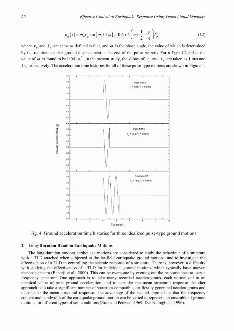
artificially simulated pulse-type motions are considered. A near-field ground motion recorded at the Sylmar station during the 1994 Northridge earthquake is considered in the present study. The velocity time histories of the fault-parallel and fault-normal motions are presented in Figure 3. It is clear that the fault-normal component is a pulse-type motion. To understand the nature of TLD-structure interaction for the pulse-type motions, artificially generated pulse motions as described by Makris (1997) are also considered in this study. Three different types of pulse motions are taken, denoted as Type-A, Type-B and Type–C2 motions and approximated by simple trigonometric functions.
Fig. 3 Velocity time histories of the fault-normal and fault-parallel components of Sylmar
record of 1994 Northridge earthquake
The analytical expression of ground acceleration of a Type-A pulse motion is given by
( ) sin ; 02
pg p p p
vu t t t Tω ω= ≤ ≤ (10)
where pv is the amplitude of velocity pulse, and pT (= 2 pπ ω ) is the predominant period and duration
of the pulse. In the present study, pv = 1 m/s and pT = 1 s are considered.
For the Type-B pulse motion, the analytical expression for ground acceleration is given by
( ) sin ; 02g p p p pu t v t t Tπω ω = + ≤ ≤
(11)
where the values of pv and pT are considered as 1 m/s and 1 s, respectively, for the present study.
The near-fault ground motions, where the displacement history exhibits one or more long-duration cycles, are approximated by a Type-C pulse. An n-cycle ground acceleration time history is approximated by a Type-Cn pulse defined as
60 Effective Control of Earthquake Response Using Tuned Liquid Dampers
( ) ( ) 1sin ; 02g p p p pu t v t t n Tϕω ω ϕ
π = + ≤ ≤ + −
(12)
where pv and pT are same as defined earlier, and ϕ is the phase angle, the value of which is determined by the requirement that ground displacement at the end of the pulse be zero. For a Type-C2 pulse, the value of ϕ is found to be 0.041 7.π In the present study, the values of pv and pT are taken as 1 m/s and 1 s, respectively. The acceleration time histories for all of these pulse-type motions are shown in Figure 4.
Fig. 4 Ground acceleration time histories for three idealized pulse-type ground motions
2. Long-Duration Random Earthquake Motions
The long-duration random earthquake motions are considered to study the behaviour of a structure with a TLD attached when subjected to the far-field earthquake ground motions, and to investigate the effectiveness of a TLD in controlling the seismic response of a structure. There is, however, a difficulty with studying the effectiveness of a TLD for individual ground motions, which typically have uneven response spectra (Banerji et al., 2000). This can be overcome by evening out the response spectra over a frequency spectrum. One approach is to take many recorded accelerograms, each normalized to an identical value of peak ground acceleration, and to consider the mean structural response. Another approach is to take a significant number of spectrum-compatible, artificially generated accelerograms and to consider the mean structural response. The advantage of the second approach is that the frequency content and bandwidth of the earthquake ground motion can be varied to represent an ensemble of ground motions for different types of soil conditions (Ruiz and Penzien, 1969; Der Kiureghian, 1996).
ISET Journal of Earthquake Technology, September-December 2012 61
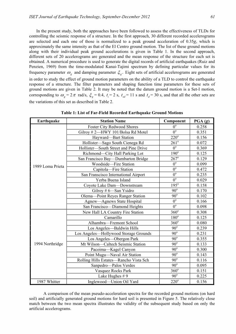
In the present study, both the approaches have been followed to assess the effectiveness of TLDs for controlling the seismic response of a structure. In the first approach, 30 different recorded accelerograms are selected and each one of those is normalized to a peak ground acceleration of 0.35g, which is approximately the same intensity as that of the El Centro ground motion. The list of these ground motions along with their individual peak ground accelerations is given in Table 1. In the second approach, different sets of 20 accelerograms are generated and the mean response of the structure for each set is obtained. A numerical procedure is used to generate the digital records of artificial earthquakes (Ruiz and Penzien, 1969) from the time-modulated Kanai-Tajimi spectrum by defining particular values for its frequency parameter gω and damping parameter .gξ Eight sets of artificial accelerograms are generated in order to study the effect of ground motion parameters on the ability of a TLD to control the earthquake response of a structure. The filter parameters and shaping function time parameters for these sets of ground motions are given in Table 2. It may be noted that the datum ground motion is a Set-I motion, corresponding to gω = 2π rad/s, gξ = 0.4, it = 2 s, sdt = 11 s and dt = 30 s, and that all the other sets are the variations of this set as described in Table 2.
Table 1: List of Far-Field Recorded Earthquake Ground Motions
Earthquake Station Name Component PGA (g) Foster City Redwood Shores 0o 0.258
Gilroy # 2—HWY 101/Bolsa Rd Motel 0o 0.351 Hayward—Bart Station 220o 0.156
Hollister—Sago South Cienega Rd 261o 0.072 Hollister—South Street and Pine Drive 0o 0.369
Richmond—City Hall Parking Lot 190o 0.125 San Francisco Bay—Dumbarton Bridge 267o 0.129
Woodside—Fire Station 0o 0.099 Capitola—Fire Station 0o 0.472
San Franscisco International Airport 0o 0.235 Yerba Buena Island 0o 0.029
Coyote Lake Dam—Downstream 195o 0.158 Gilroy # 6—San Ysidro 90o 0.170
Olema—Point Reyes Ranger Station 90o 0.102 Agnew—Agnews State Hospital 0o 0.166
1989 Loma Prieta
San Francisco—Diamond Heights 0o 0.098 New Hall LA Country Fire Station 360o 0.308
Camarillo 180o 0.125 Alhambra—Fremont School 360o 0.080 Los Angeles—Baldwin Hills 90o 0.239
Los Angeles—Hollywood Storage Grounds 90o 0.231 Los Angeles—Obergon Park 90o 0.355
Mt Wilson—Caltech Seismic Station 90o 0.133 Pacoima—Kagel Canyon 90o 0.300
Point Mugu—Naval Air Station 90o 0.143 Rolling Hills Estates—Rancho Vista Sch 90o 0.116
Sanpedro—Palos Verdes 90o 0.095 Vasquez Rocks Park 360o 0.151
1994 Northridge
Lake Hughes # 9 90o 0.225 1987 Whitter Inglewood—Union Oil Yard 220o 0.156
A comparison of the mean pseudo-acceleration spectra for the recorded ground motions (on hard soil) and artificially generated ground motions for hard soil is presented in Figure 5. The relatively close match between the two mean spectra illustrates the validity of the subsequent study based on only the artificial accelerograms.

62 Effective Control of Earthquake Response Using Tuned Liquid Dampers
Table 2: Filter Parameters and Shaping Function Time Parameters for Various Sets of Artificially Generated Ground Motions
Set No. gω (rad/s) gξ it (s) sdt (s) dt (s) PGA (g) I 2.0π 0.4 2 11 30 0.35 II 1.5π 0.4 2 11 30 0.35 III 3.0π 0.4 2 11 30 0.35 IV 2.0π 0.2 2 11 30 0.35 V 2.0π 0.6 2 11 30 0.35 VI 2.0π 0.4 2 4 30 0.35 VII 2.0π 0.4 2 11 30 0.5 VIII 2.0π 0.4 2 11 30 1.0
Fig. 5 Comparison of mean pseudo-acceleration response spectra for artificially generated
ground motions for hard soil and 30 recorded accelerograms
RESPONSE OF STRUCTURES TO GROUND MOTIONS
1. Response to Pulse-Type Motions
Figure 6 compares the time histories of the total acceleration response of a typical structure with and without TLD for both the components of the Sylmar ground motion of the 1994 Northridge earthquake. The fault-normal component is a short-duration pulse-type motion with the peak ground acceleration occuring in the first pulse (see Figure 3), and it may be observed that the TLD is not effective as it does not get a chance to dissipate energy. The fault-parallel component is relatively a longer-duration ground motion with the peak ground acceleration occuring after a few seconds of strong motion and therefore the TLD is clearly more effective in this case.

ISET Journal of Earthquake Technology, September-December 2012 63
Fig. 6 Total acceleration response time histories of a typical structure, with and without TLD,
when subjected to the two components of Sylmar motion of 1994 Northridge earthquake
A more detailed study of TLD-structure interaction for the pulse-type motions is done by considering the three idealized pulse motions shown in Figure 4. Peak responses at the top of a typical structure due to the Type-A, Type-B and Type-C2 motions and percentage reductions in those due to the TLD of varying mass ratios are presented in Table 3. From this table, it is seen that the TLD is not significantly effective for the Type-A pulse motion, as compared to the Type-B and Type-C2 pulse motions. The reason behind this can be traced from the comparisons of the typical time-history plots for total acceleration at the top of a representative structure with and without TLD as shown in Figure 7 for the three pulse motions. It is seen that since the Type-A pulse is of extremely short duration, the peak response occurs in the very first cycle itself. Therefore, for this pulse motion, the TLD, in which the sloshing has just started, does not get a chance to dissipate energy and thus proves to be ineffective. For the Type-B pulse, the peak occurs in the second cycle and is of higher intensity than that for the Type-A pulse, and therefore the TLD is obviously more effective. The Type-C2 pulse is of relatively longer duration and the peak occurs after a few cycles. Therefore, in this case, the TLD gets more time to dissipate energy and is consequently most effective. Thus, it can be concluded that a TLD is effective for the pulse-type motions only if the peak response of the structure occurs more than two cycles of vibration after the start of the strong motion.
Table 3: Peak Responses at the Top of a Typical Structure, Due to Pulse Ground Motions, and Percentage Reductions in Those Due to a TLD of Varying Mass Ratios
Percentage Reduction in amax Type of Ground Motion ( )amax 0
(m/s2) µ = 1% µ = 2% µ = 4% Type-A 9.29 3.34 5.59 8.83 Type-B 18.37 4.08 7.89 15.19 Type-C 39.76 10.49 16.0 24.0

64 Effective Control of Earthquake Response Using Tuned Liquid Dampers
Fig. 7 Total acceleration response time histories of a typical structure, with and without TLD,
when subjected to the three idealized pulse ground motions
2. Response to Long-Duration Ground Motions
The mean peak total acceleration responses at the top of certain representative structures, due to the 30 recorded accelerograms listed in Table 1 and scaled to the peak ground acceleration of 0.35g, and percentage reductions in those due to a TLD of mass ratio of 4% are presented in Table 4. The same results for the artificially generated ground motions for hard soil are also presented in this table. From this comparison, it is seen that the TLD is effective across the spectrum of structural frequencies considered for both actual and artificial ground motions and that the level of effectiveness is approximately the same for both types of ground motions. For the recorded motions, it is seen that on average the TLD reduces 25% of the response for 2% structural damping, while it reduces 15% response for 5% structural damping. For a specific structure of 0.75-s period, the response reduction is as much as 32% for 2% structural damping and about 20% for 5% structural damping. This shows that a TLD is indeed effective in controlling the earthquake response of structures. Furthermore, this illustrates the fact that a TLD becomes progressively less effective as the structural damping increases, since the overall effect of the added viscous damping due to sloshing in the TLD gets reduced. A TLD absorbs and dissipates energy based on the level of sloshing and wave breaking and, irrespective of the amount of structural damping; this energy dissipation remains the same for a particular excitation level of the TLD. The base motion of the TLD is sx which is same as the total acceleration of the top of the structure. As the base motion decreases, sloshing action in the TLD is reduced and hence its effectiveness reduces. As the structural damping is increased, total acceleration at the top of the structure is reduced and hence the base motion of the TLD also reduces. This results in less sloshing and therefore

ISET Journal of Earthquake Technology, September-December 2012 65
the effectiveness of TLD reduces. For a particular amount of sloshing, the added damping is constant. For 2% structural damping, the damping added by the TLD is thus higher than that for 5% structural damping, though the structure is subjected to same excitation in both cases. For a structure having larger structural damping, the damping added by energy dissipation in the TLD is smaller as a fraction of the overall damping. Thus, the effectiveness of TLD is reduced. The effectiveness of TLD increases with mass ratio due to the increased sloshing action. For 5% damping, a TLD with the mass ratio of 2% will not be effective. Therefore in this study, for 2% damping, the mass ratio of TLD is considered as 2%, while for 5% damping, the mass ratio is considered as 4%.
Table 4: Mean Peak Responses at the Top of Representative Structures, Due to 30 Recorded Far-Field Motions and Artificial Motions for Hard Soil, and Percentage Reductions in Those Due to a TLD with 4% Mass Ratio
Response Due to 30 Recorded Far-Field Motions
Response Due to Artificial Motions for Hard Soil Structural Properties
sT (s) sξ (%) ( )amax 0
(m/s2)
Percentage Reduction in amax
( )amax 0
(m/s2)
Percentage Reduction in amax
2.0 9.68 21.8 12.21 36.5 0.5 5.0 7.75 15.35 8.57 22.5 2.0 8.47 17.71 9.33 28.0 0.67 5.0 6.83 12.74 6.98 21.6 2.0 8.77 32.38 8.53 29.8 0.75 5.0 6.53 19.90 6.19 18.9 2.0 6.34 22.08 6.26 28.0 1.0 5.0 4.94 14.98 4.68 18.8 2.0 3.24 20.68 4.19 22.7 1.5 5.0 2.55 12.16 3.30 14.6 2.0 2.03 20.20 3.52 26.1 2.0 5.0 1.64 13.41 2.70 17.8
EFFECT OF GROUND MOTION PARAMETERS
Ground motions are characterized by various parameters. The following are those important parameters which affect the behaviour of structures when they are subjected to earthquake ground motions: a) frequency content and bandwidth of ground motion, b) duration of stationary intensity of ground motion, and c) intensity of ground motion.
1. Effect of Frequency Content and Bandwidth
In order to study the effect of frequency content of ground motion, three sets of ground motions are generated with different central frequencies, keeping other parameters constant. The central frequencies considered are gω = 1.5 ,π 2π and 3π rad/s (i.e., corresponding to the Set-II, Set-I and Set-III motions in Table 3). To study the effect of frequency bandwidth of ground motion, three sets of ground motions with different bandwidth parameters are again generated, while keeping the other parameters constant. The bandwidth parameters considered are gξ = 0.2 (narrow), 0.4 (medium) and 0.6 (broad) (i.e., corresponding to the Set-IV, Set-I and Set-V motions in Table 2). The percentage reductions by a TLD in the mean peak acceleration responses at the top of various structures for the above sets of ground motions are shown in Table 5. From this table, it can be seen that the TLD is more effective for those structures whose natural frequencies are close to the central frequency of ground motion and thus the structural response is very large anyway. Around the central frequency of

66 Effective Control of Earthquake Response Using Tuned Liquid Dampers
ground motion, the effectiveness of TLD increases as the central frequency of ground motion increases. For gω = 1.5π rad/s (or gT = 1.33 s) and sT = 1.33 s, the reduction in response is 22%; for gω =
2.0π rad/s (or gT = 1.0 s) and sT = 1.0 s, the reduction in response is 24.94%; and for gω = 3.0π rad/s
(or gT = 0.67 s) and sT = 0.67 s, the reduction in response is 27.94% (with the structural damping remaining unchanged at 2%). The reasoning for this kind of behavior of TLD is that as the central frequency of ground motion increases, the base acceleration of TLD is higher, thus leading to a greater sloshing action as stated above. A TLD can thus become more effective even when the tuning is not perfect.
Table 5: Percentage Reductions in Mean Peak Acceleration Responses at Top of Various Structures Due to a TLD (with µ = 2% for sξ = 2% and µ = 4% for sξ = 5%) for Different Sets of Ground Motions with Varying Central Frequencies and Varying Bandwidths
Percentage Reductions in Mean Peak Accelerations for Structural Properties Ground Motions with Different Central
Frequencies Ground Motions with Different
Bandwidth Parameters
sT (s) sξ (%) gω = 1.5π ( gT = 1.33 s)
gω = 2.0π ( gT = 1.0 s)
gω = 3.0π ( gT = 0.67 s) gξ = 0.2 gξ = 0.4 gξ = 0.6
2.0 13.71 16.44 28.54 9.45 16.44 20.99 0.5 5.0 8.58 8.59 13.01 1.37 8.59 8.67 2.0 9.30 15.98 27.94 8.79 15.98 18.5 0.67 5.0 3.69 7.82 17.22 1.17 7.82 10.93 2.0 11.99 16.23 24.03 10.67 16.23 17.78 0.75 5.0 4.15 8.58 19.27 −0.85 8.58 11.94 2.0 19.64 24.94 23.33 29.95 24.94 23.44 1.0 5.0 8.54 18.94 22.21 21.49 18.94 19.59 2.0 22.0 22.29 18.66 24.13 22.29 20.23 1.33 5.0 13.86 16.19 14.26 17.67 16.19 15.25 2.0 21.86 20.74 17.60 20.99 20.74 19.89 1.5 5.0 20.20 20.63 16.55 19.52 20.63 18.93 2.0 14.03 12.03 11.97 12.12 12.03 12.31 2.0 5.0 15.58 12.37 13.02 11.10 12.37 12.83
It may be noted here that the TLD is significantly effective even for a higher damping ratio of 5%, when the structure frequency is close to the central frequency of ground motion. Thus, it can be concluded that a TLD is more effective, when the structure frequency is close to the central frequency of ground motion and the response of the structure without TLD is large. Furthermore, a TLD is most effective for the high-frequency ground motions. This is so because TLDs basically work on two principles: (i) tuning, and (ii) sloshing. At a higher frequency, when the structure frequency is close to (but not exactly equal to) the frequency of ground motion, a TLD is subjected to more sloshing, and hence more energy dissipation takes place. Unlike a TLD, a TMD is effective only when the frequency ratio is unity. It can be seen from Table 5 that at gω = 3.0π rad/s (or gT = 0.67 s), the effectiveness of a TLD is maximum for the structures having periods from 0.5 to 1.0 s, as compared to the effectiveness of a TLD for the same structures but with gω = 2.0π and 1.5π rad/s (i.e., with gT = 1.0 and 1.33 s).
As stated earlier, the effectiveness of a TLD is primarily due to the sloshing action rather than tuning. The sloshing action is more whenever the base motion of the TLD is higher and is more effective even though tuning is not perfect. For instance in Table 5, for the 0.5-s structure, the base motion is higher than that for the 0.67-s structure. Hence, the TLD is more effective for the 0.5-s structure compared to the 0.67-s structure, even though the TLD is tuned to the 0.67-s structure as in Banerji et al. (2000).

ISET Journal of Earthquake Technology, September-December 2012 67
The parameter gξ represents the bandwidth of ground motion. Table 5 shows the reductions in
structure response for the ground motions with different bandwidth parameters, gξ = 0.2, 0.4 and 0.6, but
for a constant central frequency, gω = 2.0π rad/s (i.e., for the Set-IV, Set-V and Set-VI motions). It is clear from these results that a TLD is more effective for the 1-s structure for all bandwidths and that this effectiveness is maximum for gξ = 0.2. As mentioned earlier, the effectiveness of a TLD broadly depends on the sloshing action. At these parameters, the TLD is subjected to the maximum base motion and hence is found to be more effective. It may also be seen from Table 5 that for the broad-banded motions, the TLD is effective over a broad spectrum of structural frequencies, whereas for the narrow-banded ground motions, the TLD is effective only if the structural frequency is in the vicinity of the central frequency of ground motion. However, it should be noted that for the structures with natural frequencies in the vicinity of the central frequency of ground motion, the effectiveness of TLD increases as the bandwidth of ground motion decreases. For example, the response reduction is fairly constant at around 20% across the spectrum of structural frequencies for the broad-banded ground motions, whereas for the narrow-banded ground motions, the response reduction varies from around 30% for the 1-s structure to around 9% for the 0.5-s structure. The reason for the above behaviour can be traced to the fact that the narrow-banded ground motions tend to become harmonic ground motions, for which a TLD is effective only if the frequencies of the structure, TLD and excitation are very close to each other. According to Der Kiureghian (1996), as the soil becomes softer, the central frequency gω and
bandwidth gξ are reduced. Hence, for softer soils, a TLD will be increasingly more effective for a structure whose natural frequency is close to the central frequency of ground motion, but will be significantly less effective for those structures whose frequencies are away from the central frequency of ground motion. It has already been stated in this paper that the effectiveness of a TLD reduces with an increase in the structural damping but is not significantly affected by the structure frequency for the broad-banded ground motions. It is, of course, assumed here that the TLD for each structure is designed as per the procedure given in Banerji et al. (2000). Thus, the TLD properties, except for the mass ratio, vary with the natural frequency of structure.
2. Effect of Duration of Stationary Intensity
In this study two different sets of ground motions with different values of sdt are considered. One set is having sdt = 11 s (corresponding to the Set-I motion in Table 2), while the other set is having sdt = 4 s (corresponding to the Set-VI motion in Table 2). The percentage reductions in the mean peak responses at the top of various structures due to a TLD for these sets of ground motions are shown in Table 6. From these results, it can be seen that for the relatively short-period structures, the duration of the stationary intensity of ground motion does not have significant effect on the performance of TLD. However, for the relatively long-period structures, the TLD is more effective for the ground motions having a longer duration of strong motion. This is because in the case of the ground motions with a short duration of strong motion, the short-period structures get a chance to vibrate for at least a few cycles within the strong-motion duration, while for the long-period structures, the 4-s strong-motion duration motion becomes like a pulse-type motion.
3. Effect of Ground-Motion Intensity
In order to study the effect of the intensity of ground motion, three different sets of ground motions with varying intensities are generated, while keeping the other parameters unchanged. The peak ground accelerations (PGAs) considered for these motions are 0.35g, 0.5g and 1.0g (corresponding to the Set-I, Set-VII and Set-VIII motions in Table 2). The mean peak total acceleration responses at the top of various structures due to these sets of ground motions and percentage reductions in those due to a TLD are presented in Table 7. From this table, it is clear that the TLD is more effective as the intensity of ground excitation increases. This is a highly desirable property of the TLD, which essentially behaves as a nonlinear viscous damper. The reason for this can be traced to the basic energy dissipation mode for a TLD. At a higher ground-excitation intensity, the TLD is subjected to a larger base motion; this results in a greater amount of sloshing with wave breaking taking place, which increases energy dissipation in the

68 Effective Control of Earthquake Response Using Tuned Liquid Dampers
TLD. However, it is to be noted here that at a further higher level of excitation (say, of 1.0g peak ground acceleration), the sloshing-slamming phenomenon takes place. An experimental study on TLDs at high levels of excitation by Banerji et al. (2010) has shown that this phenomenon results in greater energy dissipation. Hence, at the higher levels of excitation, a TLD becomes in reality much more effective than that predicted by the present numerical model.
Table 6: Percentage Reductions in Mean Peak Acceleration Responses at Top of Various Structures Due to a TLD (with µ = 2% for sξ = 2% and µ = 4% for sξ = 5%) for Artificial Ground Motions with Varying Durations of Stationary Intensity sdt
Structural Properties Percentage Reduction in Mean Peak Acceleration
sT (s) sξ (%) sdt = 11 s sdt = 4 s
2.0 16.44 16.23 0.5 5.0 8.59 11.01 2.0 15.98 15.24 0.67 5.0 7.82 7.95 2.0 16.23 13.89 0.75 5.0 8.58 11.02 2.0 24.94 20.84 1.0 5.0 18.94 20.89 2.0 22.29 11.94 1.33 5.0 16.19 13.01 2.0 20.74 15.64 1.5 5.0 20.63 15.30 2.0 12.03 8.39 2.0 5.0 12.37 10.38
Table 7: Mean Peak Total Acceleration Responses at Top of Various Structures, Due to Different Sets of Ground Motions of Varying Intensities (i.e., PGAs), and Percentage Reductions in Those Due to a TLD (with µ = 2% for sξ = 2% and µ = 4% for sξ = 5%)
Structural Properties
Mean Peak Total Acceleration at Top of Structures without TLD, ( )amax 0
(m/s2)
Percentage Reduction in Mean Peak Total
Acceleration Due to TLD
sT (s) sξ (%) 0.35g 0.5g 1.0g 0.35g 0.5g 1.0g 2.0 9.77 13.96 27.92 16.44 16.36 20.63 0.5 5.0 7.75 11.07 22.14 8.59 8.05 8.28 2.0 12.54 17.91 35.82 15.98 20.50 28.33 0.67 5.0 9.43 13.48 26.95 7.82 9.07 16.30 2.0 12.34 17.62 35.24 16.23 19.68 28.23 0.75 5.0 9.59 13.70 27.39 8.58 9.01 17.90 2.0 13.84 19.78 39.55 24.94 28.40 34.89 1.0 5.0 10.30 14.71 29.43 18.94 18.97 25.52 2.0 10.38 14.83 29.65 22.29 25.32 31.25 1.33 5.0 7.75 11.07 22.14 16.19 17.16 24.56 2.0 9.36 13.37 26.74 20.74 22.86 29.02 1.5 5.0 7.14 10.20 20.41 20.63 21.11 26.75 2.0 6.43 9.19 18.37 12.03 14.16 18.29 2.0 5.0 5.23 7.47 14.94 12.37 14.38 16.79

ISET Journal of Earthquake Technology, September-December 2012 69
SUMMARY AND CONCLUSIONS
A comprehensive study on the effectiveness of a TLD in controlling the earthquake response of structures has been carried out by considering various types of ground motions. It has been found that though the TLD adds damping to the structure, it is not effective in reducing the response of structures for the extremely short-duration pulse-type motions. However, if the pulse duration is long enough for the peak response to occur after at least two cycles of structural vibration, the TLD becomes progressively more effective. For the longer-duration ground motions, the TLD has been found to be quite effective. It has also been shown that the artificially generated ground motions considered in this study accurately reflect the characteristics of recorded ground motions. Finally, by varying the parameters of the artificially generated ground motions, the effect of ground motion parameters on the effectiveness of a TLD in reducing the structural response has been investigated. An interesting point that needs recapitulation here is that a TLD becomes increasingly more effective as the ground-motion intensity increases. Therefore, a TLD is one passive vibration control device that is more effective for the more intense ground motions.
NOTATIONS
a = half the tank length of TLD
0max )(a = mean peak total acceleration at the top of shear-beam structure
b = width of TLD tank
sc = damping coefficient of shear-beam structure
daC and frC = coefficients to account for wave breaking in TLD
c = wave speed/constant used in ground motion intensity function F = resultant base shear in TLD in global X-direction g = acceleration due to gravity
h = water depth in TLD tank
sk = stiffness of shear-beam structure
sm = mass of shear-beam structure
s = surface contamination factor
pT = predominant period
t = time (in s)
it = duration of the parabolic build-up of ground motion
sdt = duration of the stationary intensity of ground motion
dt = total duration of ground motion
0max )(u = mean peak displacement at the top of shear-beam structure
gu = ground acceleration
su = velocity component at the free surface in X-direction
xu = translation at the top of structure (for shear-beam/cantilever structure)
xu = velocity at the top of structure (for shear-beam/cantilever structure)
xu = total acceleration at the top of structure (for shear-beam/cantilever structure)
pv = amplitude of the velocity of pulse-type motions
x = horizontal distance from the centre of TLD

70 Effective Control of Earthquake Response Using Tuned Liquid Dampers
sx = base displacement of TLD
max)( sx = amplitude of the motion of structure’s top without TLD
sx = base acceleration of TLD
∆ = depth ratio of TLD tank λ = damping parameter due to liquid sloshing η = free-surface elevation of water in TLD tank
gω = frequency parameter for artificially generated ground motions
sω = natural frequency of structure
lω = fundamental sloshing frequency of TLD
pω = predominant frequency of pulse-type motions
µ = mass ratio
ν = kinematic viscosity of liquid in TLD
gξ = bandwidth parameter for artificially generated ground motions
sξ = damping ratio for shear-beam structure
ρ = mass density of liquid in TLD tank
ϕ = phase angle
REFERENCES
1. Banerji, P., Murudi, M., Shah, A.H. and Popplewell, N. (2000). “Tuned Liquid Dampers for Controlling Earthquake Response of Structures”, Earthquake Engineering & Structural Dynamics, Vol. 29, No. 5, pp. 587–602.
2. Banerji, P., Samanta, A. and Chavan, S.A. (2010). “Earthquake Vibration Control of Structures Using Tuned Liquid Dampers: Experimental Studies”, International Journal of Advanced Structural Engineering, Vol. 2, No. 2, pp. 133–152.
3. Chaiseri, P., Fujino, Y., Pacheco, B.M. and Sun, L.M. (1989). “Interaction of Tuned Liquid Damper (TLD) and Structure—Theory, Experimental Verification and Application”, Structural Engineering/Earthquake Engineering, JSCE, Vol. 6, No. 2, pp. 273s–282s.
4. Den Hartog, J.P. (1956). “Mechanical Vibrations”, McGraw-Hill, New York, U.S.A. 5. Der Kiureghian, A. (1996). “A Coherency Model for Spatially Varying Ground Motions”, Earthquake
Engineering & Structural Dynamics, Vol. 25, No. 1, pp. 99–111. 6. Fujino, Y., Sun, L., Pacheco, B.M. and Chaiseri, P. (1992). “Tuned Liquid Damper (TLD) for
Suppressing Horizontal Motion of Structures”, Journal of Engineering Mechanics, ASCE, Vol. 118, No. 10, pp. 2017–2030.
7. Jangid, R.S. and Kelly, J.M. (2001). “Base Isolation for Near-Fault Motions”, Earthquake Engineering & Structural Dynamics, Vol. 30, No. 5, pp. 691–707.
8. Kamrani-Moghaddam, B., Rahimian, M. and Ghorbani-Tanha, A.K. (2006). “Performance of Tuned Mass Dampers for Response Reduction of Structures under Near-Field and Far-Field Seismic Excitations”, Proceedings of the 4th International Conference on Earthquake Engineering, Taipei, Taiwan, Paper No. 112 (on CD).
9. Makris, N. (1997). “Rigidity-Plasticity-Viscosity: Can Electrorheological Dampers Protect Base-Isolated Structures from Near-Source Ground Motions?”, Earthquake Engineering & Structural Dynamics, Vol. 26, No. 5, pp. 571–591.
10. Matta, E. (2011). “Performance of Tuned Mass Dampers against Near-Field Earthquakes”, Structural Engineering and Mechanics, Vol. 39, No. 5, pp. 621–642.

ISET Journal of Earthquake Technology, September-December 2012 71
11. Modi, V.J., Welt, F. and Seto, M.L. (1995). “Control of Wind-Induced Instabilities through Application of Nutation Dampers: A Brief Overview”, Engineering Structures, Vol. 17, No. 9, pp. 626–638.
12. Pinelli, J.-P., Gutierrez, H., Hu, S. and Casier, F. (2003). “Multiple Distributed Tuned Mass Dampers: An Exploratory Study”, Proceedings of the XL2003 (Response of Structures to Extreme Loading) Conference, Toronto, Canada (on CD).
13. Ruiz, P. and Penzien, J. (1969). “Probabilistic Study of the Behavior of Structures during Earthquakes”, Report EERC 69-3, University of California, Berkeley, U.S.A.
14. Sakai, F., Takaeda, S. and Tamaki, T. (1989). “Tuned Liquid Column Damper—New Type Device for Suppression of Building Vibrations”, Proceedings of the International Conference on Highrise Buildings, Nanjing, China, Vol. 2, pp. 926–931.
15. Sun, L.M., Fujino, Y., Pacheco, B.M. and Isobe, M. (1989). “Nonlinear Waves and Dynamic Pressures in Rectangular Tuned Liquid Damper (TLD)—Simulation and Experimental Verification”, Structural Engineering/Earthquake Engineering, JSCE, Vol. 6, No. 2, pp. 251s–262s.
16. Sun, L.M., Fujino, Y., Pacheco, B.M. and Chaiseri, P. (1992). “Modelling of Tuned Liquid Damper (TLD)”, Journal of Wind Engineering & Industrial Aerodynamics, Vol. 43, No. 1-3, pp. 1883–1894.
17. Tamura, Y., Fujii, K., Ohtsuki, T., Wakahara, T. and Kohsaka, R. (1995). “Effectiveness of Tuned Liquid Dampers under Wind Excitation”, Engineering Structures, Vol. 17, No. 9, pp. 609–621.
18. Taniguchi, T., Der Kiureghian, A. and Melkumyan, M. (2008). “Effect of Tuned Mass Damper on Displacement Demand of Base-Isolated Structures”, Engineering Structures, Vol. 30, No. 12, pp. 3478–3488.
19. Villaverde, R. (1994). “Seismic Control of Structures with Damped Resonant Appendages”, Proceedings of the First World Conference on Structural Control, Los Angeles, U.S.A., Vol. 1, pp. WP4-113–WP4-122.
20. Warburton, G.B. (1982). “Optimum Absorber Parameters for Various Combinations of Response and Excitation Parameters”, Earthquake Engineering & Structural Dynamics, Vol. 10, No. 3, pp. 381–401.
21. Yalla, S.K. and Kareem, A. (2000). “Optimum Absorber Parameters for Tuned Liquid Column Dampers”, Journal of Structural Engineering, ASCE, Vol. 126, No. 8, pp. 906–915.
22. Ye, K. and Li, L. (2009). “Study on the Dynamic Response of LRB Base-Isolated Structure under Near-Fault Pulse-like Ground Motions”, Earthquake Resistant Engineering and Retrofitting, Vol. 31, No. 2, pp. 32–38 (in Chinese).
23. Yu, J.-K., Wakahara, T. and Reed, D.A. (1999). “A Non-linear Numerical Model of the Tuned Liquid Damper”, Earthquake Engineering & Structural Dynamics, Vol. 28, No. 6, pp. 671–686.