Effect of the flow rate in - International Ground Source Heat · PDF file ·...
27
Transcript of Effect of the flow rate in - International Ground Source Heat · PDF file ·...


Effectoftheflowrateinperformanceofgroundsource
heatpumpsystems

Generally, two types of GSHP systems are distinguished depends onhow the system is coupling to the ground: open and closed systems.Currently the most common practice is borehole heat exchangerswhich can be installed in most part of the world, using a boreholealso a shallow trench or, less commonly, by exchanging heat from apond, river or lake.

Theamountofheatthatcanbetransferredbetweenthegroundandheatexchangerdependsonmanyfactorsmainlythermalconductivityofgroundandboreholethermalresistance.Intheliterature,tothebestknowledgeoftheauthorofthisarticle,thequalityofthegroundsomewhatisfixedanddependsongeographicallocation,butmeanwhileitispossibletoengineerthequalityoftheboreholestoreducethethermalresistance.Theoverallboreholethermalresistancecanhavesignificanteffectonthesystemperformanceandthereforeitshouldbekeptassmallaspossible.Theoverallboreholethermalresistanceitselfdependsonmanyfactorssuchasboreholediameter,typeofbackfilling,convectiveheattransferbetweenfluidandheatexchangers,fluidcharacteristics,positionandtypeofheatexchangerintheborehole,andsoforth.

The successful application of commercial GSHP systems relies upon the carefulconsideration of three issues: heat pump selection, loop design and pumping.This paper discusses some of the key design issues in both ground heatexchangers and heat pump systems particularly with focusing on the flow rateand its effects on the performance of the system. Guidelines in the form ofacceptable values are provided for pumping, flow rates, equipmentperformance, pressure drop and how to use the Turbo Collector®.
Therearemainlytwodifferenttypesofflow:Turbulentandlaminar.Theflowisturbulentwhenthereisintensiverearrangementoffluid.Inlaminarflowthefluidmovesinseparatelayersandparalleltothepipeaxis.Thedifferencebetweenthesetwotypesofflowisthefluidvelocity.Inturbulentflowthevelocityofthefluidisrelativelyhigh.TheReynoldsNumberwhichisadimensionlessparameterusedtodetermineanddistinguishthedifferencebetweenthetwoflowregimes.

Equation 1 shows howthe ReynoldsNumber is calculated a pipewith internal radius r:
Re=𝟐𝒓𝝆𝑸𝝁𝑨
(1)
Where ρ is the fluid density, Q the flow rate, μ is the dynamic viscosity of the fluid and A is the cross sectional area of the pipe.This is extremely important to mention that both the density ρ and the viscosity μ of the fluid in Eq. 1 are temperaturedependent particularly in the heating mode when some antifreeze must be added to it. When the temperature drops, fluidstend to show very high viscosity and from Eq. 1 it is obvious that the system needs higher flow rate to remain the turbulentregime. Turbulent flow is very important for the mixing of dissolved substances in fluids also greatly promote heat transfer. Itis well known that in order to obtain reasonably efficient heat transfer in a BHE, the flow regime should be avoided to belaminar. Therefore, it is usually desired to keep the flow within the turbulent region. This behavior is clearly shown in Figure 1.One can notice that in the lower Re in which the flow regime is laminar, the borehole thermal resistance is comparativelyhigher, however when the flow becomes turbulent the borehole thermal resistance is low. Figure 1 also shows that furtherincreases in the flow rate (higherRe) cannot affect the borehole thermal resistance anymore.


Figure1.Thedependenceofboreholethermalresistanceandfluidflowrate.3 CalculationsweremadeusingtheprogramEED.3 Basedona127mmboreholediameterwithasingleUpipe32mmSDR11and
carrierfluid25%ethyleneglycol.
It was shown that higher flow rate can improve the performance of the system by decreasing the boreholethermal resistance. However this advantage is tradeoff by higher energy consumption of the circulationpump. The circulation pump must overcome the system’s pressure drop it means a bigger pressure loss, alarger circulation pump is required and greater pump power consumption. The pressure drop that occursduring flow through a straight circular pipe depends on several factors:4
• The roughness of the inside wall of the pipe• The characteristics of fluid, like density and viscosity of the fluid, both vary with the temperature and
the type of the antifreeze, and the concentration of the antifreeze.• The flow rate and whether the flow regime is turbulent or laminar• The geometry of the pipe ( inside diameter)
Foragivenprojectmanyofabovefactorsareconstantalthougheachofthemplaysabigroleinthesystem.Sincetheaimofthispaperistostudyoftheflowratesoseveralempiricalstudieshavebeendone.

Figure2showstherelationshipofthepressuredropandtheflowrate.
y=0,1014x2 - 0,0454xR²=0,9997
0
20
40
60
80
100
120
140
160
180
200
0 5 10 15 20 25 30 35 40 45 50
FlowL/min
PressuredropKP
a
Figure2.PressuredropVSflowrateina200mboreholewithsingleUpipe40mmdiameterwithSDR11(waterasfluidat10° C)

Figure 2 illustrates that small changes in the flow rate can cause a rather big change in pressure drop, in fact with thefurther data and regression analysis it is possible to introduce a quadratic model to best fit. This means that the pressuredrop is proportional of power 2 of flow rate. Calculation shows that the flow regime is turbulent for the whole range ofthe experiment since the water was used as a fluid in this test. Meanwhile, this experimental value is in good agreementwith the theoretical values obtained from literature.
The theoretical energy consumption of the circulation pump Epump was calculated in some other research work and theyhave shown that the energy consumption of the circulation pump is roughly proportional to the third power of the flowrate.5
Pumping power is principally important and plays a big role in the coefficient of performance known as COP. According tothe definition COP is the ratio between the heat transferred in the condenser side of the heat pump Qd (the amount ofthe energy delivered by the GSHP system) and the energy input to the compressor Ecomp and circulation pump Epump as itis shown in Eq 2.
COP= 𝑸𝒅𝑬𝒄𝒐𝒎𝒑-𝑬𝒑𝒖𝒎𝒑
(2)
So far it can be concluded so far that flow rate in a GSHP system is an important factor; COP would be maximized whenthe flow rate is in an optimal set up.

Here it is worth to mention that these two criteria tend to work against eachother. In order to have a good heat transfer, the system needs to have a highflow rate and this creates poor hydraulic performance due to a high pressuredrop. This is the case particularly when we need to add antifreeze andinhibitors which in itself increases the viscosity, and on the top of this, the lowtemperature also increases the viscosity of the fluid.4 In fact unlike GSHPsystems, heat exchangers in general, have been used in industry andengineering applications for many decades.6-9

Hence, there have been continuous attempts to improve the efficiency of theheat exchangers by various methods. Generally heat transfer augmentationmethods are distinguished in three categories:
• Active method which needs some external power for the enhancementmechanism like fluid vibration
• Passive method unlike the first group- they do not require external powerto sustain the enhancements and usually designed via the modification ofthe geometry of the flow channel. For example, wire coil inserts in tubes,treated surface, rough surface, extended surface and inner finned tubes.
• Combined method, including any combination attempts of two abovemethods.

Passivetechniqueshavebeenwidelyinvestigatedbyscientistsandfromaboveclassificationitisobviouswhy.Althoughtherearehundredsofpassivemethodstoenhancetheheattransferperformance,internally-finnedtubeisoneofthemostpopularmethodsandwidelyusedtoimproveheattransfer.10Anyturbulator techniquelikeroughnessthatdisturbsthelaminarsublayerwillenhancetheheattransfer.Forexampleinasmoothpipeof40mmdiameterSDR17atRe=9000,thelaminarsublayerthicknessisabout0.35mm.Inthislayerheattransfercanonlyoccurbythermalconduction(althoughtheflowregimeisfullyturbulentinsidethepipe)thereforebyemployinganinternalfinelementdisruptsthelaminarsublayerandwillthusenhancetheheattransfer.

Many other studies also show that transition from laminar to turbulent flowoccur at a lower Reynolds number in the finned tubes.11 Other empirical studieshave illustrated that turbulators can accelerate transition to critical Reynoldsnumbers down to 700, and then shown that the heat transfer rate can beincreased up to 200% and keeping pumping power constant.12-14 It is obviousthat the geometry and the shape of the fins can play a big role in differentsystems which are not discussed here. 15,16 In design of heat exchangers,passive techniques of heat transfer augmentation can play an important role if aproper configuration can be selected based on the working condition (both flowand heat transfer conditions).8,17

However; there have been few studies and attempts on adapting turbulent promoter inGSHP systems. TheMuoviTech group one of the biggest manufacturers of geothermal heatexchangers in Europe and US, have developed a geothermal collector with a turbulatormechanism (passive type) known as the Turbo Collector ®. This collector has an internally-twisted fin that can apply for different U pipe collectors in the GSHP systems. MuoviTechhas claimed a patent pending about how to design it and its geometry.18 Figure 3 shows across section of a grooved pipe which is widely used in GSHP systems for closed systemssuch as horizontal, single and double U-pipe.
Since GSHP systems work at rather low temperatures, it is of interest to examine theeffectiveness of these collectors. Therefore several independent empirical studies havebeen carried out and below the results of some of them are reviewed. Acuna et al.19 havestudied the performance of four vertical boreholes; the specification of the studiedboreholes is mentioned in the Table 1.

Boreholename Activeboreholelength(m)
Fluid BHEdetails
BHE2 252 Water & ethanol 20% PE 40 SDR 11 3 pipe collector
BHE4 255 Waterðanol20% PE 40 SDR 17 SingleU pipe
BHE5 243 Waterðanol20% PE 40 SDR 17 SingleU pipewith spacer
BHE6 246 Waterðanol20% PE 40 SDR 17 SingleU pipeTurbo Collector
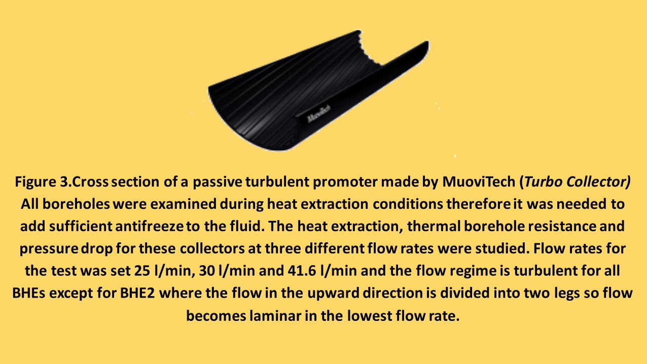
Figure3.CrosssectionofapassiveturbulentpromotermadebyMuoviTech (TurboCollector)Allboreholeswereexaminedduringheatextractionconditionsthereforeitwasneededtoaddsufficientantifreezetothefluid.Theheatextraction,thermalboreholeresistanceandpressuredropforthesecollectorsatthreedifferentflowrateswerestudied.Flowratesforthetestwasset25l/min,30l/minand41.6l/minandtheflowregimeisturbulentforall
BHEsexceptforBHE2wheretheflowintheupwarddirectionisdividedintotwolegssoflowbecomeslaminarinthelowestflowrate.

As it was expected based on the turbulent promoter theory mentioned earlier, the resultsof this research confirmed that the overall heat extraction for the inner finned collector wasthe best ´and the borehole thermal resistance showed the lowest value among the allcollectors(Figure 4) with the exception of at 41.6 l/min where BHE5 was best. Surprisingly,the BHE6 (Turbo Collector) showed improved performance even compare with the single Upipe with the spacers BHE5. Spacers play a role to avoid thermal interaction betweenupward and downward legs. This study confirms that the effect of the inner finned pipe isgreater than the spacers. Unexpectedly the pressures drop of the BHE 6(inner finnedcollector) was lowest for each flow rate compared with the other BHEs (See Figure 5).Additionally, The results of pressure drop were in line with the calculation made byPetukhov et al.5 This means that the pressure drop of the inner finned pipe can beestimatedwith the calculation of similar smooth pipes.


Figure5.PressurelossfordifferentBHEatdifferentflowrates(SourceAcunaetal.2008)19
Thisstudycarriedoutintheheatextraction(simulatingtheheatingmode).Itisalsoofinteresttoseetheresultsinthecoolingmode.Anotherstudywasthereforeconductedtocheckthebehaviorofaninner-finnedpipeattwodifferentflowratesinoneborehole.ThiswasdonebyaconventionalThermalResponseTest(TRT)inawater-filledboreholeequippedwitha200mlengthwithaTurboCollector®withdoubleU-pipe32mmSDR17.Thefluidwasmixtureofwaterandethanol15%.TheboreholewasrecoveredfollowingthefirstTRTtestthenthesecondTRTtestwasdone.Theflowrateswerechosen0.6l/sec(whichgivesusaturbulentflowregime)and20%less(0.48l/sec).Theinjectionheatrateforbothtestswas54W/m.Analysisofthedatashowedsameboreholethermalresistanceforthetwotests(dataanalyzedbylinesourcemethodandRb was0.048W/m.K).

Thismeansthatthesystemwithinner- finnedpipescanrunwiththelowerflowratewiththesameboreholeresistance.Thelowerflowratemeansconsiderablylowerpressuredropandparticularlylowerpumppowerconsumption.Itcanbeinferredanotherinterestingoutcomebycomparingtheresultofthisstudywiththepreviousone.Figure4illustratedthattheboreholethermalresistanceinallcasesdecreaseswiththeincreaseofflowrateexceptBHE6.InBHE6(TurboCollector®)thevaluesfortheboreholesthermalresistanceatdifferentflowratesareveryclosetoeachotherandalmostthesame(iftheuncertaintyistakenintoaccount).Thisbehaviorcanbeattributedtothefactthatintheinner-finnedpipethelaminarsublayeradjacenttothepipewallalreadydisturbedandminimizedbythefinssoafurtherincreasingoftheflowratecannotchangethethicknessofthislayeranymore.Thereforetheboreholethermalresistancewasnotsensitivetotheflowrate.

However, in the other heat exchangers- with increasing the flow rate thethickness of laminar sublayer could be reduced as a result the boreholethermal resistance is decreased. Now it is easier to understand why BHE6 didnot show the lowest thermal borehole resistance at the highest flow rate. Atthe highest flow rate the Re is about 6000 and as we mentioned earlier thebest performance of the turbulators is to change the critical transitionReynolds number to the lower value. Since BHE5 has spacers, there is less riskto have a thermal interaction between two flows. When the flow rate is ashigh as 41.6 l/min, the laminar sublayer becomes very thin so the boreholeresistance shows lower value. However it is worth to mention that the systemis not in the optimal condition because at a high flow rate the circulation pumpconsumes a lot of energy to overcome of the pressure loss.

Conclusions
There are several important factors in GSHP systems. Among of them is theflow rate of the secondary fluid of the ground side. Flow rate can significantlyeffect on pressure drop and also on pump energy consumption. Heatexchange characteristics of a collector with turbulator (Turbo Collector ®) in apassive mode with smooth collectors in different arrangement wereevaluated. Results indicate that micro fins can contribute to better heattransfer and pipes with the inner finned improve the performance of thesystem by lower borehole thermal resistance. This type of collectors can beapplied for both cooling and heating mode meanwhile the flow rate can be setin a lower value compared to the smooth pipes. Moreover, the pressure dropin the collectors with turbulent promoter can be estimated by theoreticalmodels.

HelicalFindesignbenefitsandperformance
LOW FLOWRATE GIVES HIGHER COP’s• Loweroperatingtimefortheloopfieldcirculationpump• 5-10%fasterpaybacktimeoftheentiresystem• Longerpumplifecycle• Lowerboreholeresistance,withlowerflowrate• Abilitytoorderfactoryassembledloopsinexcessof1,000feet
• DoubleU-Bendassembliesavailableforprojectswithlimitedspace,increasingoutputofeachborebyanadditional20%
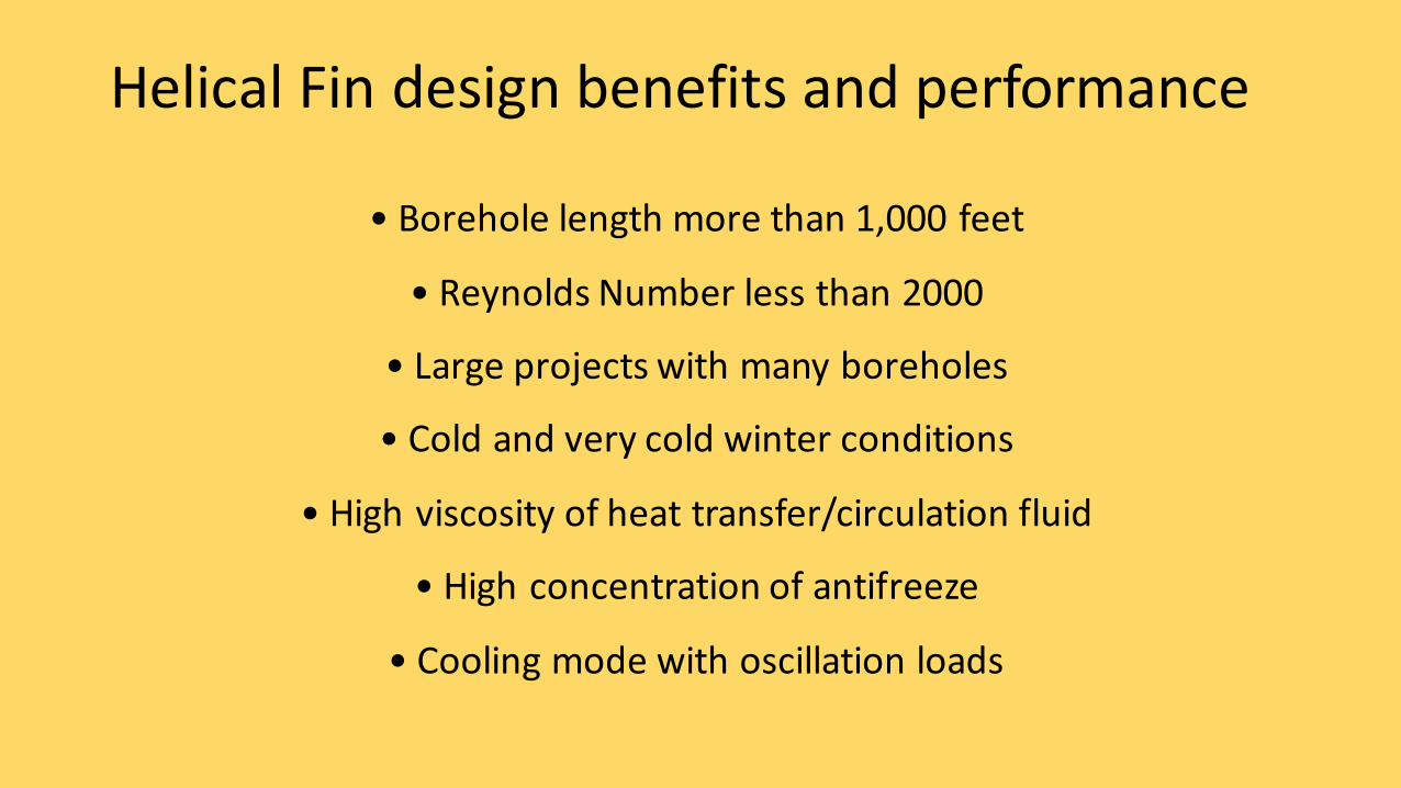
HelicalFindesignbenefitsandperformance
•Boreholelengthmorethan1,000feet
•ReynoldsNumberlessthan2000
•Largeprojectswithmanyboreholes
•Coldandverycoldwinterconditions
•Highviscosityofheattransfer/circulationfluid
•Highconcentrationofantifreeze
•Coolingmodewithoscillationloads

CANAPIPESAVEYOUMOREMONEY?• Yes! Thereisapipe toinstallintheborehole thatallowstheheatpumptouselessenergy
andrequirelessmaintenance,it’scalledtheTurboCollector,askforitbyname!
• Thisgives5-10%fasterpaybacktimeon theentiresystem.
• Additional benefitsarethattheheatpumpservicelifewillbelongerandagreatervalueonsale.
WHATISTHEMAGIC?• TurboCollector® isapatentedpipewithhelicalfinsontheinside.Thefinsprovideamore
turbulent flowandextractmoreefficientenergythanapipewithasmooth inside.
• ThecharacteristicsofTurboCollector®alsomakestheheatpumpworking longer timebeforeturning overtodirectelectricityatpeakloads.