Effect of Specific Energy Input on Microstructure and Mechanical Properties of Nickel-Base...
15
Effect of Specific Energy Input on Microstructure and Mechanical Properties of Nickel-Base Intermetallic Alloy Deposited by Laser Cladding REENA AWASTHI, SANTOSH KUMAR, KAMLESH CHANDRA, B. VISHWANADH, R. KISHORE, C.S. VISWANADHAM, D. SRIVASTAVA, and G.K. DEY This article describes the microstructural features and mechanical properties of nickel-base intermetallic alloy laser-clad layers on stainless steel-316 L substrate, with specific attention on the effect of laser-specific energy input (defined as the energy required per unit of the clad mass, kJ/g) on the microstructure and properties of the clad layer, keeping the other laser-cladding parameters same. Defect-free clad layers were observed, in which various solidified zones could be distinguished: planar crystallization near the substrate/clad interface, followed by cellular and dendritic morphology towards the surface of the clad layer. The clad layers were charac- terized by the presence of a hard molybdenum-rich hexagonal close-packed (hcp) intermetallic Laves phase dispersed in a relatively softer face-centered cubic (fcc) gamma solid solution or a fine lamellar eutectic phase mixture of an intermetallic Laves phase and gamma solid solution. The microstructure and properties of the clad layers showed a strong correlation with the laser- specific energy input. As the specific energy input increased, the dilution of the clad layer increased and the microstructure changed from a hypereutectic structure (with a compact dis- persion of characteristic primary hard intermetallic Laves phase in eutectic phase mixture) to near eutectic or hypoeutectic structure (with reduced fraction of primary hard intermetallic Laves phase) with a corresponding decrease in the clad layer hardness. DOI: 10.1007/s11661-012-1290-6 Ó The Minerals, Metals & Materials Society and ASM International 2012 I. INTRODUCTION AN extensive demand for materials with improved properties in terms of their hardness and their resistance to wear, corrosion, and oxidation has been the driving force for the development of various surface hardfacing techniques and materials. Recently, laser cladding has been explored for the deposition of less diluted and fusion-bonded thick and thin metallic coatings on a wide variety of metallic substrate materials with a low heat input. Numerous studies have shown superior characteristics of hardfacing alloys deposited by laser cladding as compared with other conventional surfacing techniques. [1–4] Laser treatments have also been employed for the densification of thermally sprayed metal alloy clad layers. [5,6] The laser-cladding technique has the advantage of depositing a controlled thickness of the clad material on a selected area of the substrate. Cobalt- and nickel-base Tribaloy intermetallic alloys have been developed as an excellent corrosion- and wear-resistant material over a wide range of tempera- tures and environments. [7] Tribaloy alloys are strength- ened by the presence of a large volume fraction of a hard intermetallic Laves phase in a much softer solid-solution phase or a eutectic phase mixture. [8–11] Among the constituent elements of Tribaloy, chromium is used to enhance corrosion resistance and strengthen the solid solution, whereas molybdenum and silicon are used to impart wear resistance by forming the intermetallic Laves phase, and nickel or cobalt provide a tough matrix. Laves phases have topologically closed-packed structures, [12] which hinder the movement of disloca- tions, making them very hard and rather brittle. [13] Therefore, Tribaloys are seldom applied in bulk form but rather are applied as coatings. [14,15] Cobalt-base Tribaloy alloys have been extensively studied as welded and clad overlays by laser-cladding technique [16–18] as well as thermal spray technique. [19–21] However, the high cost and scarcity of cobalt led to the development of cobalt-free hardfacing alloys. Further- more, in the nuclear industry, the use of cobalt-base alloys is limited due to the induced activity of long-lived radioisotope Co 60 formed. These difficulties led to the development of various nickel and iron-base alloys to replace cobalt-base hardfacing alloys. [22,23] Tribaloy T-700 is cobalt-free nickel-base alloy, described as an alternative to the cobalt-base Tribaloy for nuclear applications involving wear, corrosion, and high- temperature resistance. [24] It was demonstrated that a nickel-base alloy having composition, Ni-32 wt pct REENA AWASTHI, SANTOSH KUMAR, KAMLESH CHANDRA, B. VISHWANADH, C.S. VISWANADHAM, and D. SRIVASTAVA, Scientific Officers, and G.K. DEY, Head, are with the Materials Science Division, Bhabha Atomic Research Centre, Mumbai 400085, India. Contact e-mails: [email protected]; [email protected] R. KISHORE, Scientific Officer, is with the Post Irradiation Examination Division, Bhabha Atomic Research Centre. Manuscript submitted August 22, 2011. METALLURGICAL AND MATERIALS TRANSACTIONS A
-
Upload
kamlesh-chandra -
Category
Documents
-
view
214 -
download
0
Transcript of Effect of Specific Energy Input on Microstructure and Mechanical Properties of Nickel-Base...

Effect of Specific Energy Input on Microstructureand Mechanical Properties of Nickel-Base IntermetallicAlloy Deposited by Laser Cladding
REENA AWASTHI, SANTOSH KUMAR, KAMLESH CHANDRA, B. VISHWANADH,R. KISHORE, C.S. VISWANADHAM, D. SRIVASTAVA, and G.K. DEY
This article describes the microstructural features and mechanical properties of nickel-baseintermetallic alloy laser-clad layers on stainless steel-316 L substrate, with specific attention onthe effect of laser-specific energy input (defined as the energy required per unit of the clad mass,kJ/g) on the microstructure and properties of the clad layer, keeping the other laser-claddingparameters same. Defect-free clad layers were observed, in which various solidified zones couldbe distinguished: planar crystallization near the substrate/clad interface, followed by cellularand dendritic morphology towards the surface of the clad layer. The clad layers were charac-terized by the presence of a hard molybdenum-rich hexagonal close-packed (hcp) intermetallicLaves phase dispersed in a relatively softer face-centered cubic (fcc) gamma solid solution or afine lamellar eutectic phase mixture of an intermetallic Laves phase and gamma solid solution.The microstructure and properties of the clad layers showed a strong correlation with the laser-specific energy input. As the specific energy input increased, the dilution of the clad layerincreased and the microstructure changed from a hypereutectic structure (with a compact dis-persion of characteristic primary hard intermetallic Laves phase in eutectic phase mixture) tonear eutectic or hypoeutectic structure (with reduced fraction of primary hard intermetallicLaves phase) with a corresponding decrease in the clad layer hardness.
DOI: 10.1007/s11661-012-1290-6� The Minerals, Metals & Materials Society and ASM International 2012
I. INTRODUCTION
AN extensive demand for materials with improvedproperties in terms of their hardness and their resistanceto wear, corrosion, and oxidation has been the drivingforce for the development of various surface hardfacingtechniques and materials. Recently, laser cladding hasbeen explored for the deposition of less diluted andfusion-bonded thick and thin metallic coatings on awide variety of metallic substrate materials with a lowheat input. Numerous studies have shown superiorcharacteristics of hardfacing alloys deposited by lasercladding as compared with other conventional surfacingtechniques.[1–4] Laser treatments have also beenemployed for the densification of thermally sprayedmetal alloy clad layers.[5,6] The laser-cladding techniquehas the advantage of depositing a controlled thickness ofthe clad material on a selected area of the substrate.
Cobalt- and nickel-base Tribaloy intermetallic alloyshave been developed as an excellent corrosion- and
wear-resistant material over a wide range of tempera-tures and environments.[7] Tribaloy alloys are strength-ened by the presence of a large volume fraction of a hardintermetallic Laves phase in a much softer solid-solutionphase or a eutectic phase mixture.[8–11] Among theconstituent elements of Tribaloy, chromium is used toenhance corrosion resistance and strengthen the solidsolution, whereas molybdenum and silicon are used toimpart wear resistance by forming the intermetallicLaves phase, and nickel or cobalt provide a toughmatrix. Laves phases have topologically closed-packedstructures,[12] which hinder the movement of disloca-tions, making them very hard and rather brittle.[13]
Therefore, Tribaloys are seldom applied in bulk formbut rather are applied as coatings.[14,15] Cobalt-baseTribaloy alloys have been extensively studied as weldedand clad overlays by laser-cladding technique[16–18] aswell as thermal spray technique.[19–21]
However, the high cost and scarcity of cobalt led to thedevelopment of cobalt-free hardfacing alloys. Further-more, in the nuclear industry, the use of cobalt-basealloys is limited due to the induced activity of long-livedradioisotope Co60 formed. These difficulties led to thedevelopment of various nickel and iron-base alloys toreplace cobalt-base hardfacing alloys.[22,23] TribaloyT-700 is cobalt-free nickel-base alloy, described as analternative to the cobalt-base Tribaloy for nuclearapplications involving wear, corrosion, and high-temperature resistance.[24] It was demonstrated that anickel-base alloy having composition, Ni-32 wt pct
REENA AWASTHI, SANTOSH KUMAR, KAMLESHCHANDRA, B. VISHWANADH, C.S. VISWANADHAM, andD. SRIVASTAVA, Scientific Officers, and G.K. DEY, Head, are withthe Materials Science Division, Bhabha Atomic Research Centre,Mumbai 400085, India. Contact e-mails: [email protected];[email protected] R. KISHORE, Scientific Officer, is with the PostIrradiation Examination Division, Bhabha Atomic Research Centre.
Manuscript submitted August 22, 2011.
METALLURGICAL AND MATERIALS TRANSACTIONS A

Mo-15 wt pct Cr-3 wt pct Si (similar to the TribaloyT-700) exhibits a better wear performance than severalstainless steels and other nickel-base counterparts.[25]
These alloys have been studied as a coating deposited bythermal spray technique including detonation gun, high-velocity oxygen fuel, and sputtering.[26,27]
Austenitic stainless steels (substrate) are extensivelyused as structural materials in various industries includ-ing the nuclear industry due to their better toughnessand corrosion resistance. However, their low hardnessand poor wear resistance limit their range of applica-tions. The purpose of hardfacing is to increase thehardness of the stainless steel without affecting the bulkproperties much, as hardness is one of the propertiesused for judging the wear resistance.
Although the advantages of the laser-cladding processover other conventional techniques are well established,published literature on the laser-cladded nickel-baseintermetallic alloys (similar to Tribaloy T-700) is scarce.In our previous study on the microstructural aspects ofthe same alloy,[28] the laser-deposited clad layer wasstudied for a given specific processing parameter set oflaser power, powder feed rate, and scanning speed. Theearlier studies were further continued to enhance thescope of that study by considering more parameter sets.The effect of applied laser-specific energy input (kJ/g, oneof the crucial combined parameters associated with lasercladding) on the evolution of microstructure and phases,composition (dilution), and hence, its effect on thehardness of the laser-deposited Ni-base intermetallicalloy (Ni-Mo-Cr-Si alloy) clad layer, was analyzed andthe optimum value of this parameter for minimumdilution of the cladding was determined. The specificenergy input and the interaction time (ratio of spot size/scanning speed, seconds) are the key factors controllingthe melting and solidification, dilution, microstructure,and properties of the clad deposited by the laser-claddingtechnique.[29] In the current work, the effect of specificenergy input (kJ/g) on the microstructure and propertiesof the laser-clad layer was studied, keeping the interac-tion time constant. The microstructure and morphologyat various locations of the clad layer cross section wereinvestigated by optical microscopy, scanning electronmicroscopy (SEM), and transmission electron micro-scopy (TEM). The distribution of elements in thedifferent phases was determined by an energy-dispersivespectrometer (EDS) attached to SEM and TEM. Themicrohardness and the hardness of individual phases ofthe clad cross section were determined by using Vickersmicrohardness test and Nanoindentation, respectively.The optimum laser-cladding parameters (laser-specificenergy input and interaction time of the laser with thematerials) to obtain a defect-free clad layer with uniformmetallurgical bond and minimum dilution of clad layerwith the substrate were determined.
II. EXPERIMENTAL
The nickel-based alloy powder of chemical composi-tion listed in Table I (similar to Tribaloy T-700) wasdeposited as a hardfacing alloy on a stainless steel 316L
substrate (Table I) by laser cladding. Powder within thesize range of 10 to 53 lm with a spherical morphologywas used for the experiments. In laser-cladding exper-iments, a high-power continuous-wave CO2 laserequipped with a Metco powder feeder was employed.Three different laser-specific energy inputs (defined asthe ratio of laser power to the powder feed rate) wereestablished by varying the laser power and the powderfeed rate. Specific energy inputs of 17.14 kJ/g (P-4,PFR-14), 25.8 kJ/g (P-4, PFR-9.3), and 32.25 kJ/g (P-5,PFR-9.3), where P is the laser power in kW and PFR isthe powder feed rate in g/min, were used to analyze theeffect of laser-specific energy input on the clad charac-teristics. The interaction time of approximately 0.7 sec-ond was kept constant by keeping the scanning speed(~430 mm/min) and the spot size of the laser beam(approximately 5 mm at substrate surface) the same inall the samples. The laser power input in these exper-iments was kept more than an experimentally deter-mined minimum value required for uniform clad layerdeposition. The thicknesses of the clad layers wereapproximately 1.2 mm, and 1 mm and 0.9 mm, respec-tively, for the clad layer with specific energy input of17.14 kJ/g, 25.8 kJ/g, and 32.25 kJ/g, respectively. Afterlaser cladding, the samples were prepared for cross-sectional analysis by the metallographic polishing tech-nique using a solution of HNO3, HCl, and glycerol in aratio of 1:3:2 by volume as etchant. The characterizationof microstructure in the transverse midsection of theclad layer near the interfacial region and surface of theclad layer was performed using optical microscopy andSEM. A detailed analysis of the cladding layers and aphase analysis were performed by TEM using a JEOL-2000 FX (JEOL Ltd., Tokyo, Japan) and Tecnai-20microscopes (FEI Company, Hillsboro, OR) at variouslocations of the clad cross section. Thin foils wereprepared by cutting slices approximately 0.7 mm thickfrom the cross section of the laser-clad layer. The sliceswere ground mechanically to 100 lm. Disks with 3 mmdiameters were punched mechanically such that thesubstrate/clad interface lay at the center of the disk. Thedisks were dimpled at the center by jet-thinning tech-nique using a mixture of perchloric acid and methanol ina ratio of 1:4 (by volume) as the electrolyte at 20 V. Thedimpling produced a thin central region in the disk to beexamined in the electron microscope. The compositionalanalyses of the clad layers were performed by anEDS attached to the CAMSCAN SEM microscope(TESCAN, Brno, Czech Republic). The hardness profilesacross the substrate-clad layer interface were determinedby a Vickers microhardness tester using 100 g load on thecross section of the cladded samples at an interval of100 lm. Nanoindentation tests were performed using aBerkovich indenter with a maximum load of 3 mN to
Table I. Chemical Compositions of the Alloy Powder and the
Substrate (Weight Percent)
Elements Ni Mo Cr Si Fe C
Substrate 10 2 18 <0.01 balance <0.08Clad alloy balance 32.1 15 3.3 1 0.05
METALLURGICAL AND MATERIALS TRANSACTIONS A

evaluate the hardness of the individual phases at variouslocations of the cross section of clad layers.
III. RESULTS
A. Microhardness
All the laser-clad layers deposited at different laser-specific energy inputs appeared uniformly good withoutany discontinuities and visible surface cracks. The averagehardness of the clad layers was in the range 430 to 650VHN0.1.
[28] Thus, the hardness of all clad layers was higherthan that of the stainless steel substrate, which was in therange of 170 to 200 VHN0.1.Microhardness profiles alongthe depth direction in the transverse cross section of thecladding layers deposited at different energy inputs are
shown in Figure 1. The clad layers showed variation inhardness with laser-specific energy input. The clad layerdeposited at the lowest specific energy input (17.14 kJ/g)exhibited the highest hardness (~650 VHN0.1), nearly1.5 times that (450-500 VHN0.1) of clad layers depositedat still higher specific energy inputs.On increasing the laser-energy input from 25.8 to 32.25 kJ/g, there was only amarginal decrease in hardness. The clad layer showed anearly uniform distribution of hardness along the cladcross section. A marginal decrease in hardness near theclad–substrate interface was observed in all the clad layers.To determine the characteristics of these clads, the sampleswere further examined in detail using optical microscopy,SEM-EDS, TEM-EDS, and nanoindentation techniques.
B. Microstructural Characterization
The optical micrographs of the cross sections of theclad layers at three different energy inputs are shown inthe Figures 2 through 4. The clad layers appeareduniform, dense, and free of defects, with an excellentmetallurgical bonding with the substrate. It could be seenthat the microstructures of the substrate and the cladregion were distinctly different. In all cases, the micro-structure of the clad region was finely dendritic. The cladlayer deposited at the lowest energy input of 17.14 kJ/gexhibited a sharp interface (Figure 2(a)), whereas thelayers deposited at higher energy inputs were character-ized by a curved interface with a small heat-affected zone(Figure 3(a) and 4(a)). In all samples the solidificationstarted with a planar front morphology at the substrate/clad interface. The clad layer deposited at the lowestenergy input of 17.14 kJ/g primarily exhibited finedendritic morphology throughout the clad cross sectionextending up to the surface of the clad (Figure 2(b)) witha narrow cellular and columnar region (~20 lm) near thesubstrate/clad interface (Figure 2(a)). In contrast, both
Fig. 2—Optical micrographs of laser-clad layer deposited at lowest specific energy input of 17.14 kJ/g, showing (a) sharp substrate/clad interfaceand (b) equiaxed dendritic clad surface.
Fig. 1—Cross-sectional microhardness profile across clad/substrateinterface of clad layers deposited at different specific energy input.
METALLURGICAL AND MATERIALS TRANSACTIONS A

the clad layers deposited at higher energy input showed awell-distinguished gradient of morphology with widercolumnar and cellular regions (~100 to 150 lm) near theinterface followed by equiaxed dendritic morphology upto the surface of the clad similar to earlier observa-tions.[28] Because of the fine microstructure, no furtherinformation could be derived from optical micrographs.
The finer details and compositional analysis of thephases were carried out using SEM attached with EDS.The SEM micrographs of all the clad layers deposited atdifferent specific energy input, shown in Figures 5through 7, respectively, confirmed the presence of
different morphological regions as observed in theoptical micrographs. Two distinct contrasts of (brightand gray) phases with various morphologies were clearlyrevealed in all the clad layers.The clad layer at the lowest energy input (17.14 kJ/g)
exhibited a compact dispersion of blocky and flowerybright phase dispersed in an irregular lamellar eutecticphase (lamellar spacing ~0.5 lm) with a small propor-tion of gray phase near the substrate/clad interface(Figure 5(a)). Proceeding towards the surface of theclad, the volume fraction of bright flowery phase in thefine eutectic was seen to increase (Figure 5(b)).
Fig. 3—Optical micrographs of laser-clad layer deposited at intermediate specific energy input of 25.8 kJ/g, showing (a) curved substrate/cladinterface (b) dendritic clad surface.
Fig. 4—Optical micrographs of laser-clad layer deposited at highest specific energy input of 32.25 kJ/g, showing (a) curved substrate/cladinterface and (b) dendritic clad surface.
METALLURGICAL AND MATERIALS TRANSACTIONS A

The clad layer with intermediate energy input(25.8 kJ/g) featured coarse columnar primary dendrites(gray region) and interdendritic eutectic mixture(Figure 6(a)) near to the substrate/clad interface(~100 lm) with a narrow (~40 lm) heat affected zone.The clad surface beyond this exhibited a homogeneousmicrostructure forming eutectic colonies consisting offine lamellar eutectic phase (~0.2 to 0.3 lm interlamellarspacing, not resolved in optical micrographs) with asmall proportion of coarser bright and flowery phase.
The clad layer with the highest energy input (32.25 kJ/g)exhibited primarily equiaxed dendritic phase (grayphase) and interdendritic eutectic mixture as shown inFigure 7(b). Relatively coarser columnar dendrites wereobserved near the substrate/clad interface (Figure 7(a)).Thus, the microstructure of the clad layer deposited atthe highest energy input (32.25 kJ/g) was similar to themicrostructure of the interfacial region (~100 to 150 lm)of the clad layer with intermediate energy input of25.8 kJ/g.
Fig. 5—SE (secondary electron) micrographs of laser-clad layer (lowest specific energy input of 17.14 kJ/g, showing (arrow) (a) the bright phasewith different morphology, blocky (B), flowery (F), and lamellar eutectic (L) dispersed in gray phase (G) near substrate/clad interface and(b) increased fraction of bright phase with dendritic (flowery, F) morphology away from interface.
Fig. 6—SE micrographs of laser-clad layer (at intermediate specific energy input of 25.8 kJ/g), showing (arrow) (a) columnar dendrites (grayphase, G) with interdendritic lamellar eutectic, L (bright and dark contrast) near substrate/clad interface, and (b) lamellar eutectic phase (L)dispersed in gray phase (G) with small fraction of flowery bright phase (F) away from interface.
METALLURGICAL AND MATERIALS TRANSACTIONS A

Figure 8 shows the qualitative compositional profilesof the constituent elements across the substrate–cladinterface of all the clad layers. The alloy powder did notcontain much Fe (less than 1 wt pct), implying that theFe content observed in the clad layers came in from thesubstrate. This Fe content was used as a metallurgicalmeasure for the dilution of clad, and it was used tocompare the various clad layers. The extents of dilutionwere different in all the laser-clad layers, depending onthe applied laser-specific energy input (clearly seen in theFigures 8(a) through (c)). The extent of dilution wasfound to increase with increasing laser-specific energyinput. The quantitative compositional (spot) analysis ofthe phases at cross section of the all the laser-clad layersdeposited at different specific energy inputs are shown inTables II through IV.
The dilution of Fe in the clad layer deposited at lowestenergy input (17.14 kJ/g) was very low, passing from~15 pct at the substrate/clad interface (~40 lm) to~6 pct in the clad layer. Dilution of steel substrate fromclad materials was found to be negligible. In contrast,the dilution of clad layer deposited with intermediateenergy input (25.8 kJ/g) was high (of the order of 30 pct)near the substrate/clad interface (~100 to 150 lm) anddecreased down to 15 pct above the interface, remainingconstant along the track. A dilution (in a zone of width~40 to 50 lm) of the steel with elements from thecladding (8 to 9 wt pct Mo) was also observed. Thedilution was found to be highest, ~30 to 35 pct,throughout the clad track in the clad layer depositedat still higher energy input of 32.25 kJ/g, which indi-cated alloying of clad material with the substratethroughout the clad layer.
The quantitative analysis (Tables II through IV) ofthe phases revealed the preferential partitioning of Moand Si in the brighter phase, and Ni, Cr and Fe towards
the gray contrast phase in all the laser-clad layers. Theoverall Fe content in the laser-clad layers varieddepending on their dilution with the substrate. AnEDS analysis also revealed that the Fe content in allthe clad layers was greater near the interface anddecreased further away from interface. The partitioningof elements in the eutectic phase by TEM-EDS(Table III) analysis also revealed preferential partition-ing of Mo and Si in the one phase (bright phase inSEM) and Ni, Cr, and Fe in the other (dark phase inSEM).The above observations revealed the existence of
phases with various morphologies in the clad crosssection depending on the heat input and the dilution ofthe clad materials with the substrate. The Ni-Mo-Cr-Sisystem is known to form various brittle intermetalliccompounds that may impair the bond strength. As such,it was necessary to conduct an overall examination of thewhole clad cross section on a much finer scale. So, TEMstudies were carried out using selected-area electrondiffraction (SAED) analysis throughout the clad crosssection to reveal the structure of the fine interdendriticeutectic phase and the crystal structure of the phases withvarious morphologies (bright and gray contrast in SEM).The clad layers were examined throughout the clad crosssection by expanding the hole with ion-milling techniquein the TEM specimen initially prepared by jet-thinningtechnique. The laser-clad layer deposited at highestenergy input (32.25 kJ/g) had nearly similar microstruc-ture and composition of the phases as the interfacialregion (~150 lm) of the clad deposited at intermediateenergy input (25.8 kJ/g). Therefore, TEM studies wererestricted only to laser-clad layers deposited at 17.14 and25.8 kJ/g (as the clad layers were examined at variouslocations of the cross section). Figure 9 shows the TEMmicrographs of various regions of the clad cross section
Fig. 7—SE micrographs of laser-clad layer (at highest specific energy input of 32.25 kJ/g), showing (arrow) (a) columnar dendrites (gray phase, G)with interdendritic lamellar eutectic (L) near substrate/clad interface and (b) equiaxed dendrites (gray phase, G) with interdendritic lamellar eutectic(L) away from interface.
METALLURGICAL AND MATERIALS TRANSACTIONS A

of the laser-clad layer deposited at lowest energy input17.14 kJ/g. The presence of two phases (dark and brightcontrast) with various morphologies similar to SEMobservation (where the contrast in TEM was opposite tothat of SEM) was revealed. The fine interdendriticlamellar eutectic (lamellar spacing ~50 nm), which wasnot properly resolved in the SEM micrograph, could beclearly seen (Figure 9). The SAED pattern from both thephases (Figure 10) revealed that one phase (dark phasein TEM) was a hexagonal close-packed (hcp) interme-tallic Laves phase, and the bright-contrast (in TEM)
phase was the gamma solid solution with a face-centeredcubic crystal structure. Thus, the microstructure of theless diluted clad layer (deposited at the lowest energyinput 17.14 kJ/g) consisted of a large proportion ofprimary intermetallic Laves phase with interdendriticfine eutectic structure (gamma+Laves phase), i.e., ahypereutectic alloy. A trace amount of gamma solidsolution free of the Laves phase was also seen.The TEM micrographs (Figure 11) of the clad layer
deposited at intermediate energy input primarily exhib-ited the lamellar eutectic morphology in the clad
Fig. 8—Compositional line profiles of the constituent elements across substrate/clad interface of the clad layer deposited at (a) 17.14 kJ/g,(b) 25.8 kJ/g, (c) 32.25 kJ/g.
Table II. Compositions (Weight Percent) of Phases of Clad Layer Deposited at Lowest Energy Input (17.14 kJ/gm) Obtainedby EDS Analysis
Elements
Near Interface (~40 lm) Away from Interface
Bright (Blocky) Bright (Eutectic)* Gray Phase Bright (Flowery) Eutectic* Gray
Ni 25 32 49 32 42 55Mo 49 39 15 47 30 15Cr 12 13 18 12 18 18Si 3 3 1.5 4 4 2Fe 11 13 16 5 5 9
*In the determination of eutectic phase composition, a contribution from another phase cannot be ruled out.
METALLURGICAL AND MATERIALS TRANSACTIONS A

surface and coarser columnar dendrite (shown in SEMmicrograph Figure 6(a)) with interdendritic eutectic(Figure 11) near the substrate/clad interface. The SAEDpattern (Figure 12) from one of the eutectic phases(dark phase in TEM) was found to be hexagonal closed-packed intermetallic Laves phase and the other (bright)phase was fcc-base gamma solid-solution phase. Theinterdendritic lamellar eutectic of the interfacial region(Figure 11) grew perpendicular to the interface. Somefine regions of Laves phase with globular morphology(~200 to 300 nm) were also observed near the interfaceregion. Thus, the microstructure of the interfacial regionexhibited a hypoeutectic structure with coarser primarydendrites (Figure 6(a)) of proeutectic gamma solidsolution with interdendritic lamellar eutectic (gamma+Laves). These phases are also expected to be present inthe clad layer deposited at highest specific energy input(32.25 kJ/g) due to similar morphology and compositionas the interfacial region of the clad layer deposited atintermediate specific energy input (25.8 kJ/g). Proceed-ing towards the surface of the clad, the microstructurewas comprised of a larger proportion of lamellareutectic colonies consisting of fine lamellar eutectic ofgamma+Laves phase. These eutectic colonies weresurrounded by a trace amount of gamma solid solution(free of Laves phase); i.e., it consisted of a near-eutecticstructure. The lamellar eutectic phases were elongated inrandom orientations away from substrate/clad interface(Figure 11). The high-resolution electron micrographs,shown in Figure 13, revealed the existence of faults inthe hexagonal intermetallic Laves phases in the cladlayers.
C. Nanoindentation
The hardness and modulus of the individual phases atvarious locations of the clad cross section were deter-mined by the nanoindentation technique. Because of thesimilar microstructure and composition of the phases inthe interfacial region (~100 to 150 lm from substrate/clad interface) of the clad layer deposited at intermediatespecific energy input (25.8 kJ/g) as that of clad layerdeposited at highest energy (32.25 kJ/g) (as observed inthe previous section), the nanoindentation test wascarried out on the two laser-clad layers deposited at17.14 and 25.8 kJ/g. The values were calculated basedon the loading/unloading curves measured with aBerkovich indenter using the Oliver-Pharr method.[30]
The typical load vs depth of the indentation curvesduring loading and unloading for the intermetallic Lavesand the solid-solution phases are shown in Figure 14. Itwas observed that the depth of indentation was higherfor the NiFe gamma solid solution than that of the Mo-rich intermetallic Laves phase. This indicated that NiFegamma solid solution was softer and more ductile thanintermetallic Laves phase. The hardness and Young’smodulus of both the phases at various distances at cladcross section for both the samples deposited at 17.14 and25.8 kJ/g are presented in Tables V and VI, respectively.First, comparing the hardness of the primary phases ofboth the clad layers, it was found that the primary Lavesphase of low-diluted clad (deposited at lowest energyinput of 17.14 kJ/g) has a higher hardness (~12,700 to12,800 MPa) than the primary eutectic (9000 to10,200 MPa) of the more diluted clad (deposited at still
Table IV. Compositions (Weight Percent) of Phases of Clad Layer at Highest Energy Input (32.25 kJ/gm)
Elements
Near Interface (~150 lm)Clad Surface
Fine Lamellar Eutectic
Bright (Eutectic)* Gray Phase Bright (Eutectic)* Gray Phase
Ni 22 31 25 32Mo 33 15 30 15Cr 16 15 16 16Si 3 1 3 1Fe 25 35 26 33
*In the determination of eutectic phase composition, a contribution from another phase cannot be ruled out.
Table III. Compositions (Weight Percent) of Phases of Clad Layer at Intermediate Energy Input (25.8 kJ/gm)
Elements
Near Interface (~150 lm)Clad Surface
Fine Lamellar Eutectic (TEM-EDS)
Bright (Eutectic)* Gray Phase
Bright Gray Phase
(in SEM Micrograph)
Ni 23 32 21 47Mo 24 14 56 15Cr 16 16 11 17Si 3 1 3 1Fe 20 36 9 19
*In the determination of eutectic phase composition, a contribution from another phase cannot be ruled out.
METALLURGICAL AND MATERIALS TRANSACTIONS A

Fig. 9—TEM micrographs (a–d) at various locations (a–d) of the clad cross-section of laser-clad layer deposited at a specific energy input of17.14 kJ/g.
METALLURGICAL AND MATERIALS TRANSACTIONS A

higher energy input of 25.8 kJ/g). The primary gammasolid-solution phase in the more diluted clad layer (nearsubstrate/clad interface ~100 to 150 lm of clad depositedat the intermediate specific energy input of 25.8 kJ/g)was still softer (3500 to 3800 MPa), which is expected tobe applicable also for the gamma solid-solution phase ofthe clad layer deposited at highest energy input of32.25 kJ/g because of similar microstructure and com-position of the phases (as described in Section III–B).The eutectic mixture of clad layer at 17.14 kJ/g had alower hardness (~6500 to 6800 MPa) than the eutecticmixture (9000 to 10200 MPa) of the clad deposited at25.8 kJ/g. The hardness of the eutectic mixture wasaveraged out for four to five regions to arrive at theabove observations, as the phases were very fine foractual measurements (contribution from solid solutioncould not be ruled out). The Young’s modulus of theLaves phase was found to be more than that of thesofter solid-solution phase.
IV. DISCUSSION
The results presented on the formation of phases withdifferent morphology, composition, and volume fractiondue to different specific energy input in the lasercladding of Ni-base intermetallic alloy (similar toTribaloy-700) on stainless steel substrate are discussedbelow in the light of available information and possibletransformations in this system.
In the current work, the effect of the specific energyinput (laser power to powder feed ratio, kJ/g) on themicrostructure and properties of the laser-clad layer wasinvestigated, keeping the interaction time constant. Theoptimized laser-processing parameters (specific energyinput and interaction time) resulted in dense, defect-freeclad layers with a uniform metallurgical bonding withthe substrate. The sharp substrate/clad interface(Figure 2(a)) in the clad layer deposited with lowestenergy input (17.14 kJ/g) suggested that the heat input
was just sufficient to melt the thin layer of the substratewith no heat-affected zone and led to dilution of the cladlayer to the small depth (~40 lm). In contrast, the curvedinterface with small heat-affected zones in the other cladlayers (Figures 3(a) and 4(a)) was due to extensivemeltingof the substrate, which resulted from the higher energyinput.The fine structure found in all the clad layers was due
to the high power density of the laser beam, whichresulted in a high temperature gradient and rapidsolidification with a high cooling rate. Furthermore,the finer structure of the laser-clad layer with lowerspecific energy input of 17.14 kJ/g was due to highercooling rate associated with less superheating of thesubstrate as compared to clad layers deposited withhigher energy inputs (25.8 and 32.25 kJ/g). In all the cladlayers, the solidification started with planar front growthat the interface, which is due to the fact that at theinterface, the substrate acts as heat sink, where thethermal gradient is high and solidification velocity is low.A high ratio of temperature gradient (G) to solidificationrate (R) leads to planar solidification morphology.[31,32]
As the liquid–solid interface grows, the temperaturegradient decreases gradually and the solidification rateincreases, leading to changes of solidification morphol-ogy to cellular and dendritic depending on the heat input.The wider (~100 to 150 lm) cellular and columnar
region near the substrate/clad interface (Figures 3(a) and4(a)) of the clad layers deposited at higher energy input(25.8 and 32.25 kJ/g) as compared to narrow (~20 lm)columnar region (Figure 2(a)) of the clad layer depositedat lowest energy input (17.14 kJ/g) can also be under-stood in terms of applied specific energy input andassociated superheating of the substrate. Lower specificenergy input leads to less superheating of the substrateand, hence, a higher cooling rate for the solidificationprocess. Therefore, lower ratio of G/R led to the finedendritic structure with narrow columnar region(~20 lm). Increasing the heat input results in more
Fig. 10—Bright-field image (a) of the clad layer (deposited at 17.14 kJ/g) and corresponding SAED patterns. (b) Shows spot 1 of hcp intermetallicLaves phase and (c) fcc-based gamma solid solution of spot 2 in (a).
METALLURGICAL AND MATERIALS TRANSACTIONS A
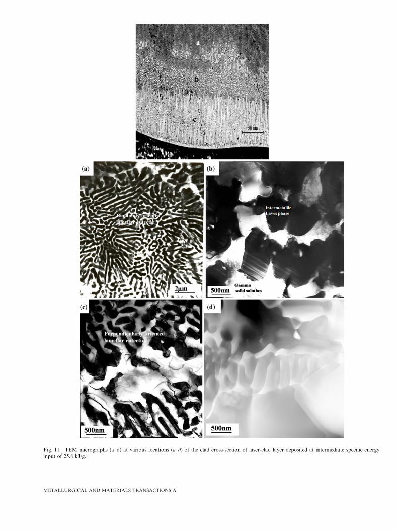
Fig. 11—TEM micrographs (a–d) at various locations (a–d) of the clad cross-section of laser-clad layer deposited at intermediate specific energyinput of 25.8 kJ/g.
METALLURGICAL AND MATERIALS TRANSACTIONS A

superheating of the substrate and lower solidificationrate, which means a higher G/R ratio, leading to anincreased tendency towards cellular growth at the interface
(Figures 3(a) and 4(a)). Later, on further decrease oftemperature gradient away from substrate/clad interface,it changes to dendritic growth (Figures 3(b) and 4(b)).
Fig. 12—Bright-field image (a) of the lamellar eutectic phases of the clad layer (deposited at 25.8 kJ/g) and corresponding SAED patterns.(b) Shows spot 1 of hcp intermetallic Laves phase and (c) fcc-based gamma solid solution of spot 2 in (a).
Fig. 13—Faults within hcp intermetallic Laves phase in the clad layers: (a) deposited at 17.14 kJ/g and (b) deposited at 25.8 kJ/g.
Fig. 14—Load vs depth of indentation curves: 1) intermetallic Laves phase and 2) solid-solution phase.
METALLURGICAL AND MATERIALS TRANSACTIONS A

All the cladding layers were grossly characterized bythe presence of primary hard intermetallic Laves phase(hcp) dispersed in relatively softer fcc gamma solidsolution or eutectic mixture of intermetallic Laves phaseand fcc NiFe gamma solid solution. The phases presentcorresponded to the microstructural observations ofalloy powder and cast structure of Ni-Mo-Cr-Sialloy.[7,10] According to the literature, the formation ofLaves phase was attributed to the presence of Mo and Siin excess to their solubility limits. The observation ofpreferential partitioning of Mo and Si towards theintermetallic Laves phase (Table II through IV) alsosupports the same. No Laves phase was reported inbinary Ni-Mo or ternary Ni-Mo-Cr systems.[33] Onatomic size considerations alone, a Laves phase would beexpected, but according to Bardos et al.,[33] the value ofe/a (electron/atom) is too high for Laves phase forma-tion. However, on the addition of Si a hexagonal Lavesphase does form, from which it was concluded that the Siacts as an electron acceptor and decreases the e/a ratio toa more favorable value (usually found to be less than 8)for Laves phase formation. Silicon is a minor (~3 wt pct)constituent of Tribaloy. Gladyshevskii and Kuzma[34] intheir study of Ni-Mo-Si systems were the first to identifya Laves phase in a system relevant to these wear-resistantalloys. Silicon was found to stabilize the Laves phasesand other complex intermetallic phases in transitionmetal systems.[35,36] It was demonstrated[36] that the
stabilized Laves phases are of the hexagonal C14(MgZn2) type. The Laves phase formed in the laser-cladlayer was also found to posses hcp crystal structure.The heat input also affects the extent of dilution of clad
materials with the substrate, volume fraction of thecharacteristic hard phase, and hence, the hardness ofthe clad layers. The successive increase in Fe content inthe clad layers with a corresponding increase in specificenergy input was due to more melting and alloying of theclad material with the substrate. The low diluted (lessthan 10 pct) clad layer exhibited hypereutectic structurewith compact dispersion of characteristic primary Lavesphase in the eutectic (gamma+Laves) mixture. Theincrease in Fe dilution (~15 to 20 pct) in the laser-cladlayer resulted in decrease in volume fraction of primaryLaves phase with near eutectic structure (lamellar) andhypoeutectic structure with still higher dilution(~ >30 pct). The volume fraction discussed was basedon qualitative estimation (relative) of the volume frac-tion of the phases observed in microstructural studies.The decrease in proportion of the Laves phase may bedue to overall decrease in Si content from original 3 wtpct (as confirmed by EDS analysis) as the heat input and,hence, dilution of Fe was increased. Si is known toincrease the propensity for Laves phases in manysystems.[35] Mason and Rawlings[10,37] also found adecrease in volume fraction of primary Laves phase withreduction in the Si content and increase in Fe content in
Table V. Nanoindentation Data at Various Locations of the Clad Layer Cross Section Deposited at Lowest
Energy Input (17.14 kJ/gm)
Location
Hardness (MPa) Modulus (GPa)
Soft Matrix (Fine Eutectic)* Hard Phase (Laves) Soft Phase Hard Phase (Laves)
1 Distance frominterface (micron)
850 6670 ± 180 12700 ± 200 280 ± 15 345 ± 14450 6640 ± 210 12800 ± 150 250 ± 10 345 ± 18250 6500 ± 140 12790 ± 180 247 ± 10 320 ± 16
2 Dilution zone(10 to 20 lm)
4107 ± 110 280 ± 10
3 Substrate 2100 ± 85 200 ± 5
*In the determination of eutectic phase, the hardness contribution from matrix cannot be ruled out.
Table VI. Nanoindentation Data at Various Locations of the Clad Layer Cross Section Deposited at IntermediateEnergy Input (25.8 kJ/gm)
Location
Hardness (MPa) Modulus (GPa)
Soft Matrix (Solid Solution) Hard Phase (Laves Eutectic)* Softer Matrix Hard Phase (Eutectic)*
1 Distance frominterface (micron)
900 4700 ± 200 10200 ± 350 250 ± 15 320 ± 35300 4400 ± 200 9600 ± 250 250 ± 15 320 ± 35150 3800 ± 150 9100 ± 200 230 ± 15 320 ± 2550 3600 ± 150 8500 ± 150 220 ± 12 350 ± 15
2 Planar zone 2300 ± 200 200 ± 103 Substrate 2010 ± 50 190 ± 5
*In the determination of eutectic phase, the hardness contribution from matrix cannot be ruled out.
METALLURGICAL AND MATERIALS TRANSACTIONS A

Tribaloy alloy systems. The dilution by Fe was also seento decrease the Ni content of the matrix as well as theLaves phase. So the Fe probably had also an importantrole in decreasing the volume fraction of the Laves phase.Due to lower solubility of Mo in Fe, the Mo segregatedaway from the primary solidified gamma solid-solutionphase (in more diluted clad layer ~30 pct) and lead tointerdendritic eutectic. The dilution of Fe does not resultin a change in the crystal structure of the phases formedin the clad layers. According to Mittal et al.,[35] the Lavesphases occur at AB2 stochiometry (where A is largeratom than the atom B), the Si stabilized Laves phaseshave been observed at a fixed A element content of about33.3 at. pct normally at A2B3Si and ABSi compositions.For the Laves phase in the laser-clad layers of Ni-Mo-Cr-Si systems, it is reasonable to assume that the largerMo atoms occupy A lattice sites and the smaller Cr, Ni,Fe and Si atoms occupy the B sites.[10] Based on thisassumption and EDS analysis of phases performed, thecharacteristic primary Laves phase in less diluted(<10 pct) laser-clad layer is nearly stoichiometric having33 at. pct Mo with the formula Mo(NiSiCrFe)2. Theeutectic phase mixture of less diluted clad has less Mocontent, as the Mo was more concentrated in compactlydispersed primary Laves phase. The eutectic Laves phasein more diluted clad layer is Mo rich with 40 at. pct Mowith formula Mo1.3(NiSiCrFe)2, calculated based on acompositional analysis. In the interfacial region of all theclad layers, a larger proportion of solid-solution phaseand smaller proportion of intermetallic Laves phase wasalso due to more dilution of Fe near the interface. Thismay be beneficial, as a larger proportion of brittleintermetallic phase near the interface would haveimpaired the bond strength due to the brittle nature ofthe intermetallic Laves phases.
The hardness of the clad layers mainly depends on thedilution from the substrate, microstructure, and themorphology of various phases. Thus, the higher hardness(~650 HV0.1) of less diluted (<10 pct) clad layer (depos-ited at lowest energy input 17.14 kJ/g) was associatedwith compact dispersion of hard intermetallic Lavesphases in the extremely fine softer lamellar eutecticmixture (gamma+Laves), i.e., hypereutectic structure.In contrast, the more diluted clad (15 to 30 pct) depositedat a higher energy input (25.8 and 32.25 kJ/g), whichexhibited primarily lamellar eutectic or hypoeutecticstructure with a smaller proportion of primary hardintermetallic Laves phase, resulted in lower hardness(~500 to 430 HV0.1). No distinct variation in hardnesswas observed in the clad layer deposited at 25.8 and32.25 kJ/g, once the dilution exceeds a minimum of 10 to15 pct. The slight drop in the hardness near the interfacewas also caused by more dilution by Fe near the interfaceand progressive decrease towards the surface of the clad.The decrease in hardness of more diluted clad layer canalso be attributed to the reduction of strain-hardeningeffect caused due to the presence of Fe. The clad layerdeposited with the lowest energy input of 17.14 kJ/g andinteraction time 0.7 seconds resulted in minimal dilution(~15 pct) at the substrate/clad interface, which ensured aperfect bond between the substrate and the clad layer,and the low level of dilution (~6 pct) in the laser track
confirms the high quality of laser-deposited claddings.For laser cladding, a desirable dilution extent of maxi-mum 3 to 8 pct is recommended.[38]
The microhardness results were in good agreementwith the nanohardness results. This was because thecompactly dispersed primary Laves phase in the lessdiluted (<10 pct) clad layer was harder (~12,700 to12,800 MPa) than the eutectic Laves phase (9000 to10,200 MPa) in themore diluted clad layer (Tables V andVI). This could be explained by the fact the primary Lavesphase in the case of low-diluted clad layer was nearstoichiometric, whereas the eutectic Laves phase was Morich. Similar high levels of nonstoichiometry were previ-ously reported in other Laves phases.[13,39] It was dem-onstrated that for nonstoichiometric compositions,constitutional defects (vacancy or anti-site substitution)are incorporated into intermetallic compounds.[13] Theeffect of defects in Laves phases is different from theireffects in metals and B2 compounds.[40] This is due to thefact that Laves phases have a topologically close-packedstructure, and it is very difficult for ordinary dislocationsto move. The presence of defects in Laves phases couldmake the structure less closely packed and possibly assistthe synchroshear deformation of the alloy,[40] thuspossibly leading to the softening of the Laves phase.
V. CONCLUSIONS
All the laser clad layers resulted in dense, defect-free,and metallurgically bonded clad layers of Ni-base inter-metallic alloy (Ni-Mo-Cr-Si alloy) on stainless steel-316 L substrate. Fine grains of the clad layers were due tothe high power density of the laser beam,which resulted ina high temperature gradient and rapid solidification witha higher cooling rate. A planar crystallization region wasobserved at the interface with the substrate, followed bycellular and dendritic crystallization regions towards thesurface of the clad. The clad layers were characterized bythe presence of hard molybdenum-rich hcp intermetallicLaves phase dispersed in a relatively softer fcc gammasolid solution or a very fine lamellar eutectic matrix of anintermetallic Laves phase and a solid solution. Themicrostructure and composition, and hence the hardnessof the clad layers, were closely correlated with the laser-specific energy input (one of the crucial laser-claddingparameters). Lower specific energy inputs resulted inlower dilution and higher hardness, with the hypereutec-tic clad layers featuring a compact dispersion of thecharacteristic primary hard intermetallic Laves phase inthe softer fine eutectic mixture. In contrast, higher energyinputs resulted in higher dilution and lower hardness,withthe near-eutectic and hypoeutectic clad layers featuringprimarily lamellar eutectic structure dispersed in soft solidsolution with reduced fraction of primary hard interme-tallic Laves phase. Ni-base intermetallic alloy clad layerdeposited on stainless steel substrate under optimal laser-cladding parameters (specific energy input 17.14 kJ/g,interaction time 0.7 section) exhibited high quality laser-clad layer metallugically bonded to the substrate withminimal dilution (<10 pct) and highest hardness(~650 HV0.1) associated with hypereutectic structure of
METALLURGICAL AND MATERIALS TRANSACTIONS A

primary intermetallic Laves phase dendrites dispersed inthe eutectic matrix (Laves and gamma solid solution).
REFERENCES1. S. Atamert and H.K.D.H. Bhadeshia: Metall. Trans. A, 1989,
vol. 20A, pp. 1037–53.2. A. Frenk and W. Kurz: Mater. Sci. Eng. A, 1993, vol. 173,
pp. 339–42.3. A. Tiziani, L. Giordano, P. Matteazzi, and B. Badan: Mater. Sci.
Eng., 1987, vol. 88, pp. 171–75.4. A.F.M. Arif and B.S. Yilbas: J. Mater. Eng. Perform., 2008,
vol. 17, pp. 644–50.5. Z. Liu, J. Cabrero, S. Niang, and Z.Y. Al-Taha: Surf. Coat.
Technol., 2007, vol. 201, pp. 7149–58.6. C. Navas, R. Vijande, J.M. Cuetos, M.R. Fernandez, and J. de
Damborenea: Surf. Coat. Technol., 2006, vol. 201, pp. 776–85.7. R.D. Schmidt and D.P. Ferriss: Wear, 1975, vol. 32, pp. 279–89.8. J.R. Devis: Nickel, Cobalt and Their Alloys, ASM International,
Materials Park, OH, 2000.9. A. Halstead and R.D. Rawlings: Met. Sci., 1984, vol. 18, pp. 491–
500.10. S.E. Mason and R.D. Rawlings: Mater. Sci. Tech., 1989, vol. 5,
pp. 180–85.11. M.J. Tobar, J.M. Amado, C. Alvarej, A. Gracia, A. Valera, and A.
Yanez: Surf. Coat. Technol., 2008, vol. 202, pp. 2297–2301.12. G. Sauthoff: Intermetallics,WileyVCH,Weinheim,Germany, 1995.13. C.T. Liu, J.H. Zhu, M.P. Brady, C.G. McKamey, and L.M. Pike:
Intermetallics, 2000, vol. 8, pp. 1119–29.14. Z.A. Foroulis: Wear, 1984, vol. 96, pp. 203–18.15. T.A. Wolfla and R.C. Tucker: Thin Solid Films, 1978, vol. 53,
pp. 353–64.16. C. Navas, M. Cadenas, J.M. Cuetos, and J. de Damborenea:
Wear, 2006, vol. 260, pp. 838–46.17. J. Przybylowicz and J. Kusinski: Surf. Coat. Technol., 2000,
vol. 125, pp. 13–18.18. W.C. Lin and C. Chen: Surf. Coat. Technol., 2006, vol. 200,
pp. 4557–63.19. M.O. Price, T.A. Wolfla, and R.C. Tucker: Thin Solid Films, 1977,
vol. 45, pp. 309–19.
20. G. Xiao-Xi and H. Zhang: Thermal Spray: International Advancesin Coatings Technology, ASM International, Materials Park, OH,1992, pp. 729–34.
21. G. Bolelli and L. Lusvarghi: J. Thermal Spray Technol., 2006,vol. 15, pp. 802–10.
22. J. Vikstrom: Wear, 1994, vol. 179, pp. 143–46.23. E.K. Ohriner, T. Wada, E.P. Wehlan, and H. Ocken: Metall.
Trans. A, 1991, vol. 22A, pp. 983–91.24. R.N. Johnson and D.G. Farwick: Thin Solid Films, 1978, vol. 53,
pp. 365–73.25. J.J. Demo, Jr.: U.S. Patent, to Donald Platt Ferriss: E.I. du Pont
de Nemours and Company, Wilmington, DE, Patent No.3,839,024, 1974.
26. G. Bolelli, V. Cannillo, L. Lusvarghi, M. Montorsi, F.P. Mantini,and M. Barletta: Wear, 2007, vol. 263, pp. 1397–1416.
27. G. Bolelli, L. Lusvarghi, and R. Giovanardi: Surf. Coat. Technol.,2008, vol. 202, pp. 4793–4809.
28. R. Awsathi, S. Kumar, D. Srivastava, and G.K. Dey: Pramana-J.Phys., 2010, vol. 75, pp. 1259–66.
29. K.C. Antony, K.J. Bhansali, R.W. Messler, A.F. Miller, M.O.Price, and R.C. Tucker: Metals Handbook, ASM, Materials Park,OH, 1983, vol. 6, pp. 771–93.
30. W.C. Oliver and G.M. Pharr: J. Mater. Res., 1992, vol. 7, p. 1564.31. W. Kurz and R. Trivedi: Mater. Sci. Eng. A, 1994, vol. 179,
pp. 46–51.32. W. Kurz and D.J. Fisher: Fundamentals of Solidification, Trans.
Tech. Publication, Aedermansdorf, Switzerland, 1986.33. D.I. Bardos, K.P. Gupta, and P.A. Beck: Trans. TMS-AIME,
1961, vol. 221, pp. 1087–88.34. E.I. Gladyshevskii and Y.B. Kuzma: Zh. Strukt. Khim., 1960,
vol. 1, p. 66.35. R.C. Mittal, S.K. Si, and K.P. Gupta: J. Less Common Met., 1978,
vol. 60, pp. 75–82.36. K.P. Gupta: J. Phase Equil. Diff., 2005, vol. 4, p. 26.37. S.E. Mason and R.D. Rawlings: Mater. Sci. Tech., 1994, vol. 10,
pp. 924–28.38. J.R. Davis: ASMHandbook, ASM, Materials Park, OH, 1992, vol.
6, pp. 861–72.39. W. Bruckner, K. Kleinstuck, and G.E.R. Schulze: Phys. Status
Solidi, 1967, vol. 23, p. 465.40. P.M. Hazzledine and P. Pirouz: Scripta Metall. Mater., 1993,
vol. 28, p. 277.
METALLURGICAL AND MATERIALS TRANSACTIONS A