EFFECT OF SHAPE FACTOR UPON STRESS CONCENTRATION …
12
U.P.B. Sci. Bull., Series D, Vol. 78, Iss. 4, 2016 ISSN 1454-2358 EFFECT OF SHAPE FACTOR UPON STRESS CONCENTRATION FACTOR IN ISOTROPIC/ORTHOTROPIC PLATES WITH CENTRAL HOLE SUBJECTED TO TENSION LOAD Samir DEGHBOUDJ 1 , Hamid SATHA 2 , Wafia BOUKHEDENA 3 Determining stress concentration factors is of practical importance for many engineering structures because geometric discontinuities are frequently the site of failure. In this paper, the work is carried out to analyze the stress concentration factor, around circular central hole in isotropic and orthotropic rectangular plates, subjected to tension load by using analytical and finite element method. Different plate hole diameter - width ratios (d/W) have been considered to provide global and net stress concentration factors. A comparison between FE method and analytical results obtained with Heywood and Howland formulations was carried out. The effect of length/width ratio upon stress concentration factor was also investigated. Global and net SCF were determined for a group of isotropic and orthotropic plates with various ratios (L/W), while (d/W) ratio was changed from 0.1 to 0.9. For both Isotropic and orthotropic plates, analytical formulations of Howland and Heywood are much more valid for a length-to-width ratio equal to 2. Keywords: Stress concentration factor, isotropic plates, orthotropic plates, finite element analysis. 1. Introduction Isotropic and orthotropic plates with circular holes under tensile loading have found widespread applications in various fields of engineering such as aeronautic, marine and automobile industry [1-3]. Stress concentrations around holes have big practical importance because they are the main cause of failure. In addition, crack initiation happens near the stress concentration region. The stress concentration near a geometric discontinuity like a hole is estimated by a parameter called stress concentration factor (SCF).The coefficient of stress concentration (Kt) in a plate is defined as the ratio of the actual maximum stress 1 PhD., Dept.of Mechanic, University LARBI TEBESSI of Tébessa , Algeria, e-mail: [email protected] 2 Prof., University 08 MAI 1945 of Guelma, Algeria, e-mail: [email protected] 3 Dr., Dept.of Material Science, University LARBI TEBESSI of Tébessa, Algeria, e-mail: [email protected]
Transcript of EFFECT OF SHAPE FACTOR UPON STRESS CONCENTRATION …
U.P.B. Sci. Bull., Series D, Vol. 78, Iss. 4, 2016 ISSN 1454-2358
EFFECT OF SHAPE FACTOR UPON STRESS
CONCENTRATION FACTOR IN
ISOTROPIC/ORTHOTROPIC PLATES WITH CENTRAL
HOLE SUBJECTED TO TENSION LOAD
Samir DEGHBOUDJ1, Hamid SATHA2, Wafia BOUKHEDENA3
Determining stress concentration factors is of practical importance for many
engineering structures because geometric discontinuities are frequently the site of
failure. In this paper, the work is carried out to analyze the stress concentration
factor, around circular central hole in isotropic and orthotropic rectangular plates,
subjected to tension load by using analytical and finite element method. Different
plate hole diameter - width ratios (d/W) have been considered to provide global and
net stress concentration factors. A comparison between FE method and analytical
results obtained with Heywood and Howland formulations was carried out. The
effect of length/width ratio upon stress concentration factor was also investigated.
Global and net SCF were determined for a group of isotropic and orthotropic plates
with various ratios (L/W), while (d/W) ratio was changed from 0.1 to 0.9. For both
Isotropic and orthotropic plates, analytical formulations of Howland and Heywood
are much more valid for a length-to-width ratio equal to 2.
Keywords: Stress concentration factor, isotropic plates, orthotropic plates, finite
element analysis.
1. Introduction
Isotropic and orthotropic plates with circular holes under tensile loading
have found widespread applications in various fields of engineering such as
aeronautic, marine and automobile industry [1-3]. Stress concentrations around
holes have big practical importance because they are the main cause of failure. In
addition, crack initiation happens near the stress concentration region. The stress
concentration near a geometric discontinuity like a hole is estimated by a
parameter called stress concentration factor (SCF).The coefficient of stress
concentration (Kt) in a plate is defined as the ratio of the actual maximum stress
1 PhD., Dept.of Mechanic, University LARBI TEBESSI of Tébessa , Algeria,
e-mail: [email protected] 2 Prof., University 08 MAI 1945 of Guelma, Algeria, e-mail: [email protected] 3 Dr., Dept.of Material Science, University LARBI TEBESSI of Tébessa, Algeria,
e-mail: [email protected]
144 Samir Deghboudj, Hamid Satha, Wafia Boukhedena
() acting on the zone of discontinuity to the nominal stress (nom) applied to the
plate extremity.
Several analytical, numerical and experimental researches have been
performed on stress concentration. Heywood [4], Pilkey [5] and Peterson [6]
studied different forms of stress concentration for isotropic materials and plates
with a large range of cutouts. Muskhelishvili [7], Timoshenko and Goodier [8]
examined the phenomena of stress concentration around holes for infinite width
plates and presented classical solution for bi-dimensional analysis. Howland [9]
analyzed the stress concentration in plates subjected to tension and proposed a
formulation for calculation of the stress concentration factors of an isotropic plate
with circular hole. Hwai Chung and Bin [10] developed an empirical model to
calculate the stress concentration factor in isotropic /orthotropic plates with
circular holes. Jain and Mittal [11] investigated the effect of hole’s diameter to
plate width upon stress concentration factor and deflection in isotropic,
orthotropic and laminated composite plates under different transverse static
loading condition. Troyani et al. [12] have determined the in-plane stress
concentration factors for short rectangular plates with circular holes subjected to
tensile field using finite element method. Toubal et al. [13] evaluated stress
concentration in a circular hole in composite plate. Mittal and Jain [14] studied the
effect of fibre orientation on stress concentration factor in fibrous plate with
central circular hole under transverse static loading by using two dimension finite
element methods. Hashem et al. [15] performed a numerical analysis on stress
concentration factor for randomly oriented discontinuous fiber Laminas with
circular/square holes. Mhallah and Bouraoui [16] presented experimental analysis
based on digital image correlation to determine the stress concentration factor for
orthotropic and isotropic materials. Lekhnitskii [17] et al. and Tan [18] proposed
various formulations to investigate stress concentration for infinite and finite
orthotropic plates. Enayat and David L [19] developed an efficient boundary
element method (BEM) for use in the analysis of loaded holes in composite
structures. Nicholas and Christoph studied the stress concentration factors for
cylindrically orthotropic plates [20].
The main objective of this study is to evaluate the stress concentration
factors for isotropic and orthotropic rectangular plates with central hole subjected
to axial tension (Figure1). The investigation has been carried out by using
analytical and finite element methods. A comparison between the results obtained
with Heywood and Howland formulations and finite element method has been
done. In addition, the purpose of this work is to study the effect of length/width
ratio (shape factor L/W) for isotropic/orthotropic plates under stress concentration
factor. From the above review, it can be noted that no researches have been
conducted studies on this particular subject.
Effect of shape factor upon stress concentration factor in isotropic/orthotropic plates […] load 145
2. Theoretical stress concentration factor for finite width plates with a
hole
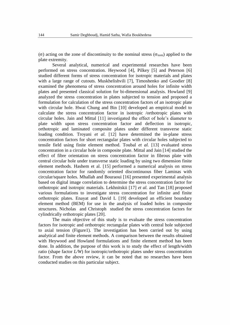
According to Peterson [6], the stress concentration factor is defined as the
ratio of the maximum stress under the actual loads in the zone of singularity (hole,
notch) to the nominal stress in the section:
nom
maxTK
(1)
where max is evaluated by numerical methods or by analytical approaches in the
case of simple geometries. It can be also estimated using experimental methods
such as photoelasticity or digital image correlation. On the other hand, nom is
computable with the aid of strength material formulas.
Fig.1. Plate with central hole subjected to uniaxial tension
According to the investigation of Heywood [4] on a finite rectangular
orthotropic plate with center hole under action of unidirectional axial load, the
SCF is given by the following equation:
MW
dKM
W
d
W
d
W
d
K
KT
Tg
Tg38
313
2
1
12
13
(2)
where K Tg and KTg are respectively the stress concentration factor in infinite
and finite plate. M, called the magnification factor, is only a function of the ratio
(d/W).
W
d/
W
d
W
d
²M
2
321
12
13
81
(3)
Equation 2 can be used for both orthotropic and isotropic finite width plates with a
central circular hole subjected to tension load for (d/W) up to 0.9 [18-21].
d
W
L
x2
x
1

146 Samir Deghboudj, Hamid Satha, Wafia Boukhedena
Leknitskii [22] introduced an expression of the stress concentration factor Kt, for
infinite orthotropic plates with circular holes KT as the form:
G
E
E
EKT
12
1112
22
1121
(4)
where E11 and E22 are elasticity moduli on the main directions, G12 is the in-
plane shear modulus and 12 is the Poisson ratio. Infinite stress concentration
factor equal to 3 for an isotropic plate with circular hole simplifies equation 2 to:
W
d
W
d
K
K
Tg
Tg
12
13
3
(5)
Another alternative to calculate the stress concentration factor is the application of
the average stress across the net section taking into account the presence of the
hole.
W
dnom
avg
1
(6)
In this case, the stress concentration factor is known as the net stress concentration
factor KTn and can be related to the global stress concentration factor KTg by
[18-21]:
KKW
dTgTn
1 (7)
The stress concentration factor using Heywood formulation will be then:
KKW
dTgHeywood
1 (8)
An expression of the global stress concentration factor, for isotropic rectangular
plate with central circular hole under uniaxial tension is given by Howland [9] as:
W
d.
W
d.
W
d.KTg 1321160
1
22840
2
(9)
And the net stress concentration factor is:
KKW
dTgHowland
1 (10)
3. Description of the problem
To study the stress concentration factor for isotropic and orthotropic
plates, we used a rectangular plate with central hole of diameter d. For both cases
the length, width and thickness of the plate were equal to 200 mm, 100 mm and 1
mm, respectively. The plates are subjected to unidirectional tensile load. The

Effect of shape factor upon stress concentration factor in isotropic/orthotropic plates […] load 147
opening diameter to width ratio (d/W) is changed from 0.1 to 0.9.The global and
the net stress concentration factor for isotropic and orthotropic plates are
calculated with Howland and Heywood formulations and compared with FE
results. In the second step of this investigation, we examined the effect of the
shape factor on SCF for different values of (d/W) ratio varying from 0.1 to
0.9.The dimensionless variable ratios employed in the analyses covered L/W = 1,
1.3 ,1.5 ,1.7, 2, 3 and 5; totaling 144 simulation cases.
4. Finite element analysis
The Finite element method (FEM) is a powerful computational technique
widely used for numerical simulation and optimization of structural geometry,
especially when dealing with stress raisers or concentrators [23-24]. In this
investigation, the geometric and FE model is carried out using the ABAQUS
software [25]. The element ‘S8R’, defined by eight nodes was employed, because
quadratic elements are more effective in capturing stress concentrations. The mesh
is refined near the hole in order to have a steady value of the maximum stress.
Figure 2 provides the example of the meshed model for d/W = 0.2 .The plate is
fixed at one end and a tensile load of 100 MPa is applied on the other one. The
plate geometry and the boundary conditions used are shown in Figure 3.
Fig. 2.Typical example of finite element
mesh for d/W = 0.2
5. Results and discussion
5.1 Isotropic plate
Since the SCF is independent of mechanical characteristics of the plate,
the material chosen for simulation is the ordinary steel. The plate has elastic
modulus E = 210000 MPa, Poisson’s ratio = 0.3 and mass density = 7800
kg/m3. For various (d/W) ratios, global and net stress concentration factors for
isotropic plate with central hole are calculated using Heywood and Howland
formulations (Equations 2, 8, 9 and 10) and compared with FE results. Table 1
show global and net stress concentration factors (KTg and KTn) obtained by FE and
analytical method. The relative error in this table is estimated by the relation:
Fig.3. Boundary conditions and loads
x2
Fixed end
100 Mpa load
x1
148 Samir Deghboudj, Hamid Satha, Wafia Boukhedena
SCF
SCFSCF
the
FEthe (11)
where SCFth and SCFFE are, respectively, the stress concentration factor
calculated with analytical and FE method. Note that infinite stress concentration
factor equals to 3 for isotropic materials with circular hole. In each computation
step, global and net stress concentration factors are obtained by dividing
maximum stress concentration extracted from ABAQUS software by the nominal
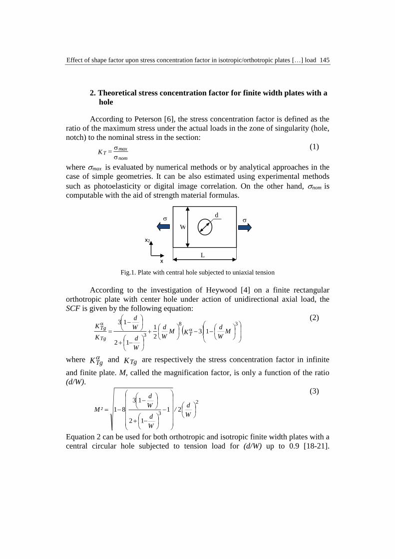
and average stress. Maximum stress distribution and stress concentration around
the hole with d/W = 0.2 are shown in Figure 4. As it can be seen from Table 1,
the agreement between results obtained with Heywood-Howland formulations and
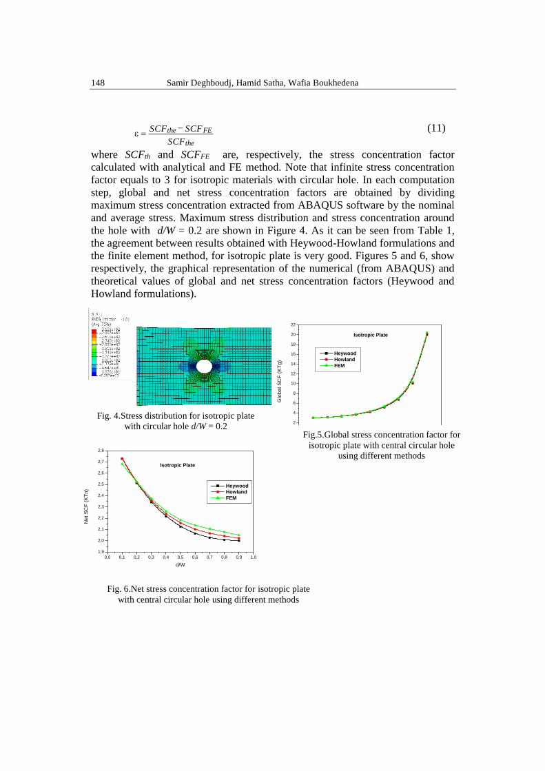
the finite element method, for isotropic plate is very good. Figures 5 and 6, show
respectively, the graphical representation of the numerical (from ABAQUS) and
theoretical values of global and net stress concentration factors (Heywood and
Howland formulations).
Fig. 4.Stress distribution for isotropic plate
with circular hole d/W = 0.2
0,0 0,1 0,2 0,3 0,4 0,5 0,6 0,7 0,8 0,9 1,0
1,9
2,0
2,1
2,2
2,3
2,4
2,5
2,6
2,7
2,8
Isotropic Plate
Net S
CF
(K
Tn)
d/W
Heywood
Howland
FEM
0,0 0,1 0,2 0,3 0,4 0,5 0,6 0,7 0,8 0,9 1,0
2
4
6
8
10
12
14
16
18
20
22
Isotropic Plate
Glo
bal S
CF
(K
Tg
)
d/W
Heywood
Howland
FEM
Fig.5.Global stress concentration factor for
isotropic plate with central circular hole
using different methods
Fig. 6.Net stress concentration factor for isotropic plate
with central circular hole using different methods

Effect of shape factor upon stress concentration factor in isotropic/orthotropic plates […] load 149
Table 1
Global and net stress concentration factor for isotropic plate with circular hole using
Heywood, Howland and FEM
Heywood Howland FEM Error
d/w KTg KHey KTg KHow avg max KTg KFEM Hey/FE How/FE
0.1 3.032 2.729 3.035 2.731 268.29 298.1 2.981 2.682 0.016 0.017
0.2 3.140 2.512 3.148 2.519 252.48 315.6 3.156 2.524 0.005 0.002
0.3 3.347 2.343 3.367 2.357 237.37 339.1 3.391 2.373 0.013 0.006
0.4 3.693 2.216 3.732 2.239 226.26 377.1 3.771 2.262 0.021 0.010
0.5 4.250 2.125 4.314 2.157 218.3 436.6 4.366 2.183 0.027 0.012
0.6 5.160 2.064 5.255 2.102 213.76 534.4 5.344 2.137 0.035 0.016
0.7 6.756 2.027 6.889 2.066 210.6 702 7.020 2.106 0.038 0.018
0.8 10.040 2.008 10.216 2.043 207.8 1039 10.39 2.078 0.034 0.016
0.9 20.010 2.001 20.237 2.023 205 2050 20.5 2.050 0.024 0.012
5.2 Orthotropic plate
This analysis was performed for a plate with one orthotropic ply. The
mechanical properties of modeled lamina are given in Table 2. Note that E11 and
E22 are the longitudinal and transversal moduli, respectively, G12, G13 and G23
shear moduli, 12 Poisson’s ratio. For orthotropic plate global and net stress
concentration factors are also calculated using analytical method (Heywood
formulation) according to Equations 2 and 8. In Table 3, obtained results are
compared with FE values. The relative error presented in this table is also
computed by Equation 11. Infinite stress concentration factor for orthotropic plate
with circular hole is evaluated by using Equation 4. Furthermore, maximum stress
has been extracted from ABAQUS software, in order to compute global and net
SCF, using Equations 1 and 6. Similar to isotropic plate, maximum stress
distribution for orthotropic plate with d/W = 0.3 is shown in Fig.re 7. In this case,
we can also see the very good agreement between results obtained with Heywood
formulation and the finite element method. The curves of numerical and analytical
values of global and net stress concentration versus (d/W) ratios are presented in
Figures 8 and 9.
For both isotropic and orthotropic cases, global stress concentration factor
(KTg) values increase as the (d/W) ratio increases. This indicates an increase in the
stress concentration factor for a reduction in the diameter (Figs. 5 and 8). In the
other hand, the net stress concentration factor (KTn) for both isotropic and
orthotropic plates decreases as the (d/W) ratio increases and this indicates a
decrease in SCF for a reduction in diameter.

150 Samir Deghboudj, Hamid Satha, Wafia Boukhedena
Table 2
The orthotropic material parameters E11(MPa) E22(MPa) 12 G12(MPa) G13(MPa) G23(MPa)
50000 14500 0.33 2560 2560 2240
Table 3
Global and net stress concentration factor for orthotropic plate with circular hole using
Heywood and FEM
Heywood FEM Error
d/w KT KTg KHeywood avg max KTg KFEM Hey/FE
0.1 5.752 5.814 5.232 507.06 563.4 5.634 5.070 0,030
0.2 5.752 6.016 4.813 467.12 583.9 5.839 4.671 0,029
0.3 5.752 6.373 4.461 439.95 628.5 6.285 4.399 0,013
0.4 5.752 6.878 4.127 411.9 686.5 6.865 4.119 0,001
0.5 5.752 7.533 3.766 367.3 734.6 7.346 3.673 0,024
0.6 5.752 8.434 3.373 335.64 839.1 8.391 3.356 0,005
0.7 5.752 9.917 2.975 288.51 961.7 9.617 2.885 0,030
0.8 5.752 13.018 2.603 264.8 1324 13.240 2.648 0,017
0.9 5.7523 22.7755 2.2775 235.1 2351 23.510 2.3510 0,0322
0,0 0,1 0,2 0,3 0,4 0,5 0,6 0,7 0,8 0,9 1,0
2,0
2,5
3,0
3,5
4,0
4,5
5,0
5,5
Orthotropic Plate
Ne
t S
CF
(K
Tn
)
d/W
Heywood
FEM
Fig.9. Net stress concentration factor for orthotropic plate with central circular hole using different
methods
Fig.7. Stress distribution for orthotropic
plate with central circular hole d/W = 0.3
0,0 0,1 0,2 0,3 0,4 0,5 0,6 0,7 0,8 0,9 1,0
4
6
8
10
12
14
16
18
20
22
24
Orthotropic Plate
Glo
bal S
CF
(K
Tg)
d/W
Heywood
FEM
Fig.8. Global stress concentration factor for orthotropic
plate with central circular hole using different methods
Effect of shape factor upon stress concentration factor in isotropic/orthotropic plates […] load 151
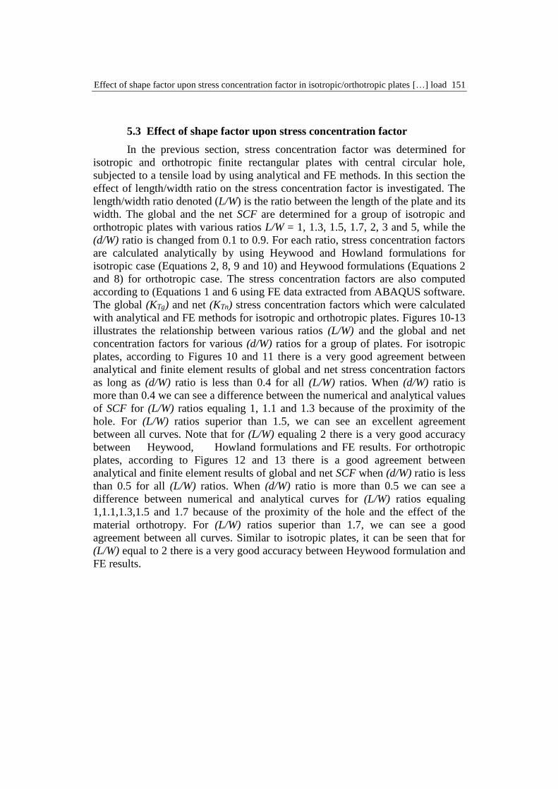
5.3 Effect of shape factor upon stress concentration factor
In the previous section, stress concentration factor was determined for
isotropic and orthotropic finite rectangular plates with central circular hole,
subjected to a tensile load by using analytical and FE methods. In this section the
effect of length/width ratio on the stress concentration factor is investigated. The
length/width ratio denoted (L/W) is the ratio between the length of the plate and its
width. The global and the net SCF are determined for a group of isotropic and
orthotropic plates with various ratios L/W = 1, 1.3, 1.5, 1.7, 2, 3 and 5, while the
(d/W) ratio is changed from 0.1 to 0.9. For each ratio, stress concentration factors
are calculated analytically by using Heywood and Howland formulations for
isotropic case (Equations 2, 8, 9 and 10) and Heywood formulations (Equations 2
and 8) for orthotropic case. The stress concentration factors are also computed
according to (Equations 1 and 6 using FE data extracted from ABAQUS software.
The global (KTg) and net (KTn) stress concentration factors which were calculated
with analytical and FE methods for isotropic and orthotropic plates. Figures 10-13
illustrates the relationship between various ratios (L/W) and the global and net
concentration factors for various (d/W) ratios for a group of plates. For isotropic
plates, according to Figures 10 and 11 there is a very good agreement between
analytical and finite element results of global and net stress concentration factors
as long as (d/W) ratio is less than 0.4 for all (L/W) ratios. When (d/W) ratio is
more than 0.4 we can see a difference between the numerical and analytical values
of SCF for (L/W) ratios equaling 1, 1.1 and 1.3 because of the proximity of the
hole. For (L/W) ratios superior than 1.5, we can see an excellent agreement
between all curves. Note that for (L/W) equaling 2 there is a very good accuracy
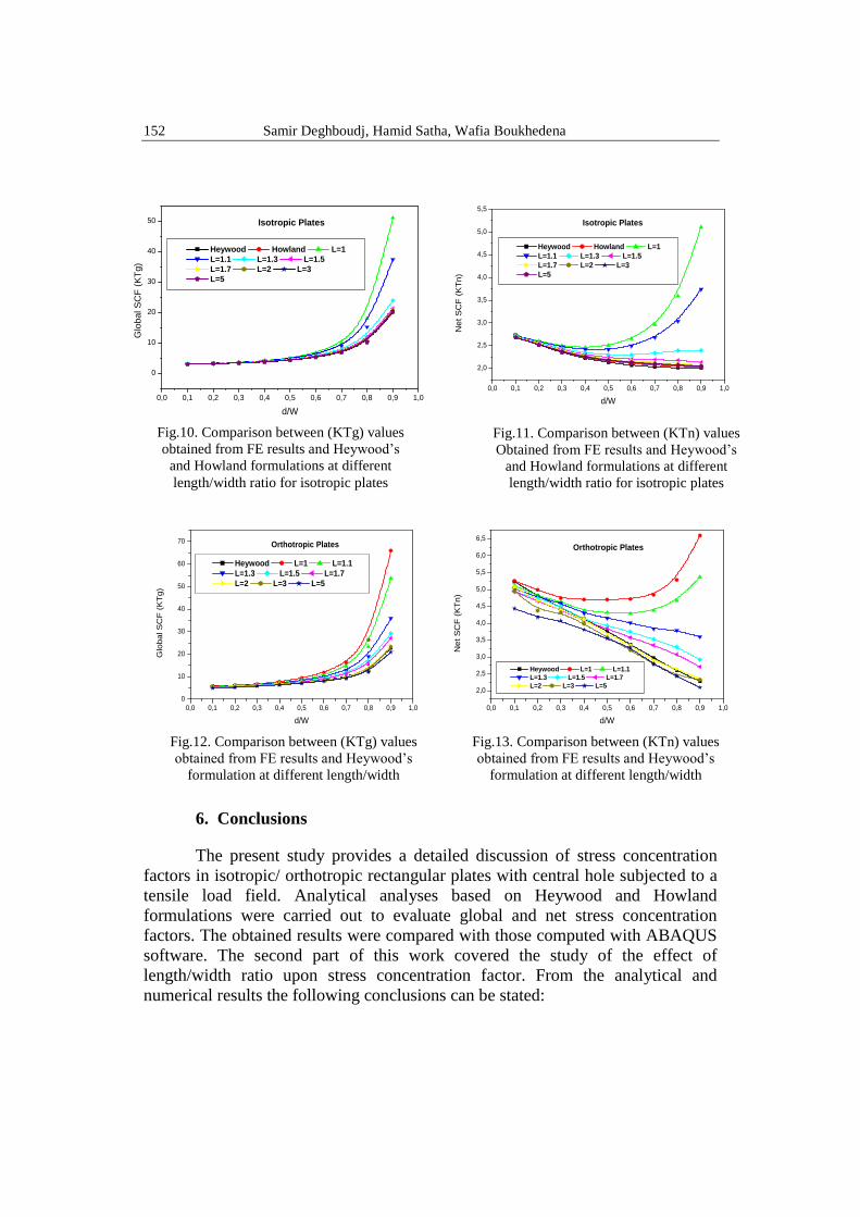
between Heywood, Howland formulations and FE results. For orthotropic
plates, according to Figures 12 and 13 there is a good agreement between
analytical and finite element results of global and net SCF when (d/W) ratio is less
than 0.5 for all (L/W) ratios. When (d/W) ratio is more than 0.5 we can see a
difference between numerical and analytical curves for (L/W) ratios equaling
1,1.1,1.3,1.5 and 1.7 because of the proximity of the hole and the effect of the
material orthotropy. For (L/W) ratios superior than 1.7, we can see a good
agreement between all curves. Similar to isotropic plates, it can be seen that for
(L/W) equal to 2 there is a very good accuracy between Heywood formulation and
FE results.
152 Samir Deghboudj, Hamid Satha, Wafia Boukhedena
6. Conclusions
The present study provides a detailed discussion of stress concentration
factors in isotropic/ orthotropic rectangular plates with central hole subjected to a
tensile load field. Analytical analyses based on Heywood and Howland
formulations were carried out to evaluate global and net stress concentration
factors. The obtained results were compared with those computed with ABAQUS
software. The second part of this work covered the study of the effect of
length/width ratio upon stress concentration factor. From the analytical and
numerical results the following conclusions can be stated:
0,0 0,1 0,2 0,3 0,4 0,5 0,6 0,7 0,8 0,9 1,0
0
10
20
30
40
50
60
70 Orthotropic Plates
Glo
bal S
CF
(K
Tg)
d/W
Heywood L=1 L=1.1
L=1.3 L=1.5 L=1.7
L=2 L=3 L=5
0,0 0,1 0,2 0,3 0,4 0,5 0,6 0,7 0,8 0,9 1,0
2,0
2,5
3,0
3,5
4,0
4,5
5,0
5,5
6,0
6,5
Orthotropic Plates
Net
SC
F (
KT
n)
d/W
Heywood L=1 L=1.1
L=1.3 L=1.5 L=1.7
L=2 L=3 L=5
0,0 0,1 0,2 0,3 0,4 0,5 0,6 0,7 0,8 0,9 1,0
0
10
20
30
40
50
Isotropic Plates
Glo
bal S
CF
(K
Tg)
d/W
Heywood Howland L=1
L=1.1 L=1.3 L=1.5
L=1.7 L=2 L=3
L=5
0,0 0,1 0,2 0,3 0,4 0,5 0,6 0,7 0,8 0,9 1,0
2,0
2,5
3,0
3,5
4,0
4,5
5,0
5,5
Isotropic Plates
Net S
CF
(K
Tn)
d/W
Heywood Howland L=1
L=1.1 L=1.3 L=1.5
L=1.7 L=2 L=3
L=5
Fig.10. Comparison between (KTg) values
obtained from FE results and Heywood’s
and Howland formulations at different
length/width ratio for isotropic plates
Fig.11. Comparison between (KTn) values
Obtained from FE results and Heywood’s
and Howland formulations at different
length/width ratio for isotropic plates
Fig.13. Comparison between (KTn) values
obtained from FE results and Heywood’s
formulation at different length/width
ratio for orthotropic plates
Fig.12. Comparison between (KTg) values
obtained from FE results and Heywood’s
formulation at different length/width
ratio for orthotropic plates

Effect of shape factor upon stress concentration factor in isotropic/orthotropic plates […] load 153
1. For isotropic plate, the stress concentration factors (KTg and KTn) values
obtained from FE method results are in a very good agreement with the analytical
values, obtained with Heywood and Howland formulations with a maximum error
of 0.038. Also, for orthotropic plate, Heywood formulation is in excellent
agreement with FE results with a maximum error of 0.032.
2. This study reveals that for both isotropic and orthotropic cases, global stress
concentration factor values increase as the (d/W) ratio increases and this indicates
an increase in SCF for a reduction in the diameter. On the other hand, the net
stress concentration factor for both isotropic and orthotropic plate decreases as the
(d/W) ratio increases and this indicates a decrease in SCF for a reduction in the
diameter.
3. For isotropic plates, there is a very good agreement between analytical and FE
results of KTg and KTn SCF, when (d/W) ratio is less than 0.4 for all (L/W) ratios.
However, in the case of (d/W) ratio greater than 0.4 one can see a difference
between the numerical and analytical values of SCF for (L/W) ratios of 1, 1.1 and
1.3 due to the proximity of the hole. For (L/W) ratios more than 1.5, an excellent
agreement between all curves is observed.
4. For orthotropic plates, there is a good agreement between the analytical and
finite element results of global and net SCF when (d/W) ratio is less than 0.5 for
all (L/W) ratios. However, in the case of (d/W) ratio more than 0.5 one can see a
difference between the numerical and analytical curves for (L/W) ratios equal to 1,
1.1,1.3,1.5 and 1.7 because of the proximity of the hole and the effect of the
material orthotropy. For (L/W) ratios greater than 1.7, a good agreement between
all curves can be noticed.
5. For isotropic plates, for (L/W) equal to 2, there is an excellent agreement
between Heywood, Howland formulations and FE results.
6. For orthotropic plates, it can be seen that for (L/W) equal to 2 there is also a
very good accuracy between Heywood formulation and FE results.
R E F E R E N C E S
[1] J. Rezaeepazhand, M. Jafari, “Stress concentration in metallic plates with special shaped
cutout”, International Journal of Mechanical Sciences, vol. 52, no. 1, 2010, pp. 96-102
[2]. S. Daghboudj, H. Satha, “Determination of the in-plane shear rigidity modulus of a carbon
non-crimp fabric from bias-extension data test”, Journal of Composite Materials., vol. 48,
no. 22, 2014, pp. 2729-2736
[3]. P.M.G.P. Moreira, S. D. Pastrama and P.M.S.T. de Castro, “ Comparative Three Dimensional
Fracture Analyses of Cracked Plates”, U.P.B. Sci. Bull., Series D, vol.69, no. 1 69, 2007,
pp.43-58
[4]. R.B. Heywood, Designing by Photoelasticity, Chapman and Hall, 1952.
[5]. W.D. Pilkey, Peterson’s Stress Concentration Factors, John Wiley & Sons, 2008.
[6]. R.E. Peterson, Stress Concentration Factors, John Wiley & Sons, 1997.
[7]. N.I. Muskhelishvili, Some Basic Problems of the Mathematical Theory of Elasticity,
Groningen, 1953.

154 Samir Deghboudj, Hamid Satha, Wafia Boukhedena
[8]. S. Timoshenko, J.N. Goodier, Theory of Elasticity, McGraw-Hill, Book Company, New York,
1951.
[9]. R.C.J. Howland, “On the Stresses in the Neighborhood of a Circular Hole in a Strip under
Tension”, Philosophical Transactions of the Royal Society of London, vol. 229, no. (670-
680), 1930, pp. 49-86
[10]. C. Hwai Chung, M. Bin, “On stress concentrations for isotropic/orthotropic plates and
cylinders with a circular hole”, Composites Part B: Engineering, vol. 34, no. 2, 2003, pp. 127-134
[11]. N.K. Jain, N.D. Mittal, “Finite element analysis for stress concentration and deflection in
isotropic, orthotropic and laminated composite plates with central circular hole under
transverse static loading”, Materials Science and Engineering: A, vol. 498, no.(1-2), 2008,
pp.115-124
[12]. N. Troyani, C. Gomes and G. Sterlacci,“Theoretical stress concentration factors for short
rectangular plates with centered circular holes”, ASME Journal of Mechanical Design, vol.
124, no. 3, 2002, pp. 126-128
[13]. L.Toubal, M.Karama and B.Lorrain, “Stress concentration in a circular hole in composite
plate”, Composite Structures., vol. 68, no. 1, 2005, pp. 31-36
[14]. N.K Jain, N.D.Mittal, “Effect of fibre orientation on stress concentration factor in a laminate
with central circular hole under transverse static loading”, Indian Journal of Engineering &
Material Sciences., vol. 15, no. 6, 2008, pp. 452-458
[15]. Z. Hashem, M. Bahador, B. Pedram, M.Gudarzi, “On Stress Concentration Factor for
Randomly Oriented Discontinuous Fiber Laminas with Circular/Square Hole”, Journal of
Science and Engineering, vol. 3, no. 1, 2013, pp. 7-18
[16]. M.M. Mhallah, C. Bouraoui, “Determination of Stress Concentration Factor for Orthotropic
and Isotropic Materials Using Digital Image Correlation (DCI)”, In: Multiphysics
Modelling and Simulation for Systems Design and Monitoring, Applied Condition
Monitoring., vol. 2, 2015, pp. 517-530
[17]. S.G. Leknitskii, S.W Tsai and T. Cheron, Anisotropic Plates, Cordon and Breach Science
Publishers, 1968.
[18]. S.C. Tan, “Finite Width Correction Factors for Anisotropic Plate Containing a Central
Opening, " Journal of Composite Materials, vol. 22,no. 11, 1988, pp. 1080-1097
[19]. M. Enayat, L.S. David, “Boundary Element Study of a Loaded Hole in an Orthotropic
Plate”, Journal of Composite Materials., vol. 20, no. 4, 1986, pp. 375-389
[20]. J.H. Nicholas, M. Christoph, “Stress Concentration Factors for Cylindrically Orthotropic
Plates”, Journal of Composite Materials., vol. 16, no. 4, 1982, pp. 313-317
[21]. B. Kambiz, R. Iraj, and R. Ferhad, “Investigation of Stress Concentration Factor for Finite-
Width Orthotropic Rectangular Plates with a Circular Opening Using Three-Dimensional
Finite Element Model”,Journal of Mechanical Engineering., vol. 54, no. 2, 2008, pp. 140-
147
[22]. S.G. Leknitskii, Theory of Elasticity of an Anisotropic Elastic Body, 1st Ed Holden-Day, San
Francisco, 1963.
[23]. A.N.Tawakol, “Stress concentration analysis in functionally graded plates with elliptic holes
under biaxial loadings”, Ain Shams Engineering Journal., vol. 5, no. 3, 2014, pp. 839-850
[24]. B.C.L. Vanam, M. Aajyalakshmi and R. Inala, “Static analysis of an isotropic rectangular
plate using finite element analysis (FEA) ”, Journal of Mechanical Engineering Research.,
vol. 4, no. 4, 2012, pp. 48-162
[25]. ***ABAQUS user manual documentation V-6.11, 2011.