Effect of servo systems on the contouring errors in INDUSTRIAL robots · · 2012-05-22method to...
14
EFFECT OF SERVO SYSTEMS ON THE CONTOURING ERRORS IN INDUSTRIAL ROBOTS Mohamed Slamani, Albert Nubiola, Ilian A. Bonev E ´ cole de technologie supe ´rieure, Montreal (Quebec), Canada E-mail: [email protected] Received August 2011, Accepted December 2011 No. 11-CSME-75, E.I.C. Accession 3315 ABSTRACT Two important aspects of the performance of a servo system, tracking errors and contour errors, significantly affect the accuracy of industrial robots under high-speed motion. Careful tuning of the control parameters in a servo system is essential, if the risk of severe structural vibration and a large contouring error is to be avoided. In this paper, we present an overview of a method to diagnose contouring errors caused by the servo control system of an ABB IRB 1600 industrial robot by measuring the robot’s motion accuracy in a Cartesian circular shape using a double ballbar (DBB) measurement instrument. Tests were carried out at different TCP (tool centre-point) speed and trajectory radii to investigate the main sources of errors that affect circular contouring accuracy. Results show that radius size errors and out-of-roundness are significant. A simple experimental model based on statistical tests was also developed to represent and predict the radius size error. The model was evaluated by comparing its prediction capability in several experiments. An excellent error prediction capability was observed. Keywords: robot; accuracy; acontouring error; adynamic error; aservo error; adouble ballbar. EFFET DES SYSTE ` MES ASSERVIS SUR LES ERREURS DE CONTOUR DANS LES ROBOTS INDUSTRIELS RE ´ SUME ´ Les erreurs de poursuite et de contour sont deux aspects importants qui influencent la pre ´cision des robots industriels en de ´placements rapides. Les parame `tres d’un syste `me asservis doivent e ˆtre soigneusement re ´gle ´s, car des parame `tres non re ´gle ´s causent souvent des vibrations de structures importantes et une grande erreur de contour. Dans cet article, nous pre ´sentons l’aperc ¸u d’une me ´thode pour diagnostiquer les erreurs de contours dues au syste `me asservi d’un robot industriel ABB IRB 1600, en mesurant la pre ´cision des mouvements du robot a ` partir des trajets circulaires en utilisant l’instrument de mesure « barre a ` billes ». Des essais ont e ´te ´ effectue ´s a ` diffe ´rentes vitesses et a ` diffe ´rents rayons de trajectoire pour e ´tudier les principales sources d’erreurs qui affectent la pre ´cision de contour circulaire. Les re ´sultats de ´montrent que les erreurs radiales et les erreurs de circularite ´s sont importantes. Un mode `le expe ´rimental simple base ´ sur des tests statistiques est de ´veloppe ´ pour repre ´senter et pre ´dire les erreurs radiales. Ensuite, le mode `le a e ´te ´e ´value ´ en comparant les pre ´dictions avec des re ´sultats expe ´rimentaux. Une excellente capacite ´ de pre ´diction a e ´te ´ observe ´e. Mots-cle ´s : robot; apre ´cision; aerreurs de contour; aerreurs dynamiques; aerreurs d’asservissement; abarre a ` billes. Transactions of the Canadian Society for Mechanical Engineering, Vol. 36, No. 1, 2012 83
Transcript of Effect of servo systems on the contouring errors in INDUSTRIAL robots · · 2012-05-22method to...
EFFECT OF SERVO SYSTEMS ON THE CONTOURING ERRORS IN INDUSTRIALROBOTS
Mohamed Slamani, Albert Nubiola, Ilian A. BonevEcole de technologie superieure, Montreal (Quebec), Canada
E-mail: [email protected]
Received August 2011, Accepted December 2011
No. 11-CSME-75, E.I.C. Accession 3315
ABSTRACT
Two important aspects of the performance of a servo system, tracking errors and contourerrors, significantly affect the accuracy of industrial robots under high-speed motion. Carefultuning of the control parameters in a servo system is essential, if the risk of severe structuralvibration and a large contouring error is to be avoided. In this paper, we present an overview of amethod to diagnose contouring errors caused by the servo control system of an ABB IRB 1600industrial robot by measuring the robot’s motion accuracy in a Cartesian circular shape using adouble ballbar (DBB) measurement instrument. Tests were carried out at different TCP (toolcentre-point) speed and trajectory radii to investigate the main sources of errors that affectcircular contouring accuracy. Results show that radius size errors and out-of-roundness aresignificant. A simple experimental model based on statistical tests was also developed to representand predict the radius size error. The model was evaluated by comparing its prediction capabilityin several experiments. An excellent error prediction capability was observed.
Keywords: robot; accuracy; acontouring error; adynamic error; aservo error; adouble ballbar.
EFFET DES SYSTEMES ASSERVIS SUR LES ERREURS DE CONTOUR DANS LESROBOTS INDUSTRIELS
RESUME
Les erreurs de poursuite et de contour sont deux aspects importants qui influencent laprecision des robots industriels en deplacements rapides. Les parametres d’un systeme asservisdoivent etre soigneusement regles, car des parametres non regles causent souvent des vibrationsde structures importantes et une grande erreur de contour. Dans cet article, nous presentonsl’apercu d’une methode pour diagnostiquer les erreurs de contours dues au systeme asservi d’unrobot industriel ABB IRB 1600, en mesurant la precision des mouvements du robot a partir destrajets circulaires en utilisant l’instrument de mesure « barre a billes ». Des essais ont eteeffectues a differentes vitesses et a differents rayons de trajectoire pour etudier les principalessources d’erreurs qui affectent la precision de contour circulaire. Les resultats demontrent queles erreurs radiales et les erreurs de circularites sont importantes. Un modele experimentalsimple base sur des tests statistiques est developpe pour representer et predire les erreursradiales. Ensuite, le modele a ete evalue en comparant les predictions avec des resultatsexperimentaux. Une excellente capacite de prediction a ete observee.
Mots-cles : robot; aprecision; aerreurs de contour; aerreurs dynamiques; aerreursd’asservissement; abarre a billes.
Transactions of the Canadian Society for Mechanical Engineering, Vol. 36, No. 1, 2012 83
1. INTRODUCTION
Higher speed is a key requirement for productivity enhancement in many automatedmanufacturing systems. High-accuracy trajectory performance is also a requirement in manyindustrial robot operations, and should be provided by the servo mechanism. A major problemwith the servo systems of industrial robots is contour errors, which occur during curve tracking.A desired curve is the shortest difference between the actual trajectory and that of the referencecommand. When the robot speed is relatively low, the contour error due to the servo system isusually acceptable. However, once high-speed and high-accuracy are demanded, for example inwater jet cutting, laser cutting, gluing, dispensing and deburring, contour errors will have asignificant effect [1]. Unfortunately, industrial robots, which were designed to carry outrepeatable tasks, are not all that accurate. While robot repeatability ranges typically from0.02 mm to 0.1 mm, accuracy is often in the order of only a few millimetres [2], and hence theneed to improve the performance of contouring control by decreasing or eliminating contourerrors as much as possible. There are two common methods for achieving this. One is to designadvanced controllers, and the other is path pre-compensation.
In circular contouring, errors can be divided into two categories: out-of-roundness errors(form errors); and radius size errors (size errors). On the robot side, out-of-roundness errors canoriginate from three major sources: geometric errors, dynamic errors and friction. Geometricerrors are usually caused by mechanical or geometrical imperfections, such as link parametererrors, flexibility and wearing of the robot’s structural elements [3]. Dynamic errors generallymanifest as overshooting, rounding-off and vibration [4]. In the case of vibration, a well-planned trajectory guarantees good path tracking and generates less excitement of the robot’smechanical structure and servo control system, and so this source of error can be avoided [5].Friction is one of the major limitations in performing high precision manipulation tasks, as itaffects both static and dynamic contouring performances, and may cause instability whencoupled to position or force feedback control [6].
Radius size error, which can be present at low speeds due to geometric error, is also present athigh velocities as a dynamic error (tracking error) caused by the servo control system [1]. Forhigh speed machine tool, it has been observed that the radius size error can reach as much asseveral hundred micrometers [7] and is proportional to the square of the feedrate and inverselyproportional to the curvature radius [8, 9].
Today, the telescopic ballbar is the most common metrology tool for assessing andcalibrating the accuracy (the XYZ part) of CMMs and machine tools, and is very popular forcalibrating parallel robots [10]. However, its use in industrial serial robots, though proposedmore than two decades ago [11], remains very limited (for example, it was used in [12], but incombination with an inclinometer, and in [13] with a reference angular encoder to characterise asix-axis serial robot). In fact, the software that comes with the popular telescopic barmanufactured by Renishaw was specifically developed for use on a machine in which thecircular motion is generated by the simultaneous movement of two orthogonal linear axes, andrequires that a defined test sequence be followed. The use of the telescopic ballbar in five-axismachine tools, when several axes are driven simultaneously or when rotary axes are driven, isstill a subject of research [14,15].
In order to improve the robot’s accuracy and efficiency, researchers are looking for ways tomeasure errors and identify their causes. In this paper, we used the Renishaw QC20-Wtelescoping ballbar (also called, double ballbar, or DBB) for measuring the contouringperformance of a non-calibrated ABB IRB 1600 industrial serial robot. We then analyzed the
Transactions of the Canadian Society for Mechanical Engineering, Vol. 36, No. 1, 2012 84
data collected and derived an empirical model of radius size error which we validatedexperimentally.
2. MODELLING APPROACH
Suppose that we have observed data for the radius size error, DR, at different TCP speeds forn cases, and would like to determine an empirical model for predicting those errors with twoindependent variables (X1 and X2) that are TCP speed-dependent.
The proposed empirical model can be written as:
DRi~b0zb1X1izb2X2izei: ð1Þ
Expressing Eq. (1) in matrix form, we have
Dr~Jbze, ð2Þ
where Dr is the n-dimensional column vector of n observations, J is the n63 matrix ofindependent variables, b is the 3-dimensional column vector of parameters, and e is the n-dimensional column vector of residual terms.
In least-squares estimation, the sum of the squares of the residual vector elements isminimised. The minimisation is equivalent to:
bb~(JTJ){1JTDr, ð3Þ
provided that the inverse of JTJ exists.
Subsequently, a stepwise regression is used to evaluate the marginal contribution of thevariables X1 and X2. In stepwise regression, terms are kept or removed from the model based onthe partial F value. The process begins by including in the model the independent variablehaving the highest simple correlation with the dependent variable DR, i.e. the highest Fj value,on condition that Fj is equal to or exceeds the critical Fa;p;n{p value (Fj§Fa;p;n{p), where n is thenumber of observations, p is the number of estimated parameters and a is the level ofsignificance. If Fj is less than Fa;p;n{p, the process terminates with no independent variablesincluded in the model.
The Fj value can be calculated by the following equation [14]:
Fj~MSM(Xj)
MSE(Xj), j~1, . . . ,p, ð4Þ
where
MSM~SSR
p, ð5Þ
MSE~SSE
n{p, ð6Þ
Transactions of the Canadian Society for Mechanical Engineering, Vol. 36, No. 1, 2012 85
SSE~Xn
i~1
(DRi{DRRi)2, ð7Þ
SST~Xn
i~1
(DRi{DR)2, ð8Þ
SSR~SST{SSE, ð9Þ
SSR~Xn
i~1
(DRRi{D�RR)2, ð10Þ
and DRRi is the estimated radius size error, D�RR is the mean radius size error, MSM is the meansquares model (mean squares due to regression), MSE is the mean square error, SSE is the sumof squares error, SST is the total variation or the total sum of the squares and SSR is theexplained variation or sum of squares due to regression.
Once the first independent variable is included in the model, the contribution of the secondindependent variable is determined for the model that already includes the first variable (sayX1). The partial F ratio in this case can be calculated by the following equation:
F2=1~MSM(X2jX1)
MSE(X2,X1): ð11Þ
If F2/1 is equal to or exceeds the critical value of Fa;p;n{p, the independent variable is included inthe model, otherwise the process terminates.
In stepwise regression, we can also test whether or not the independent variable introducedinto the model at an earlier stage may subsequently be removed, once other independentvariables have been evaluated.
3. TEST METHODS
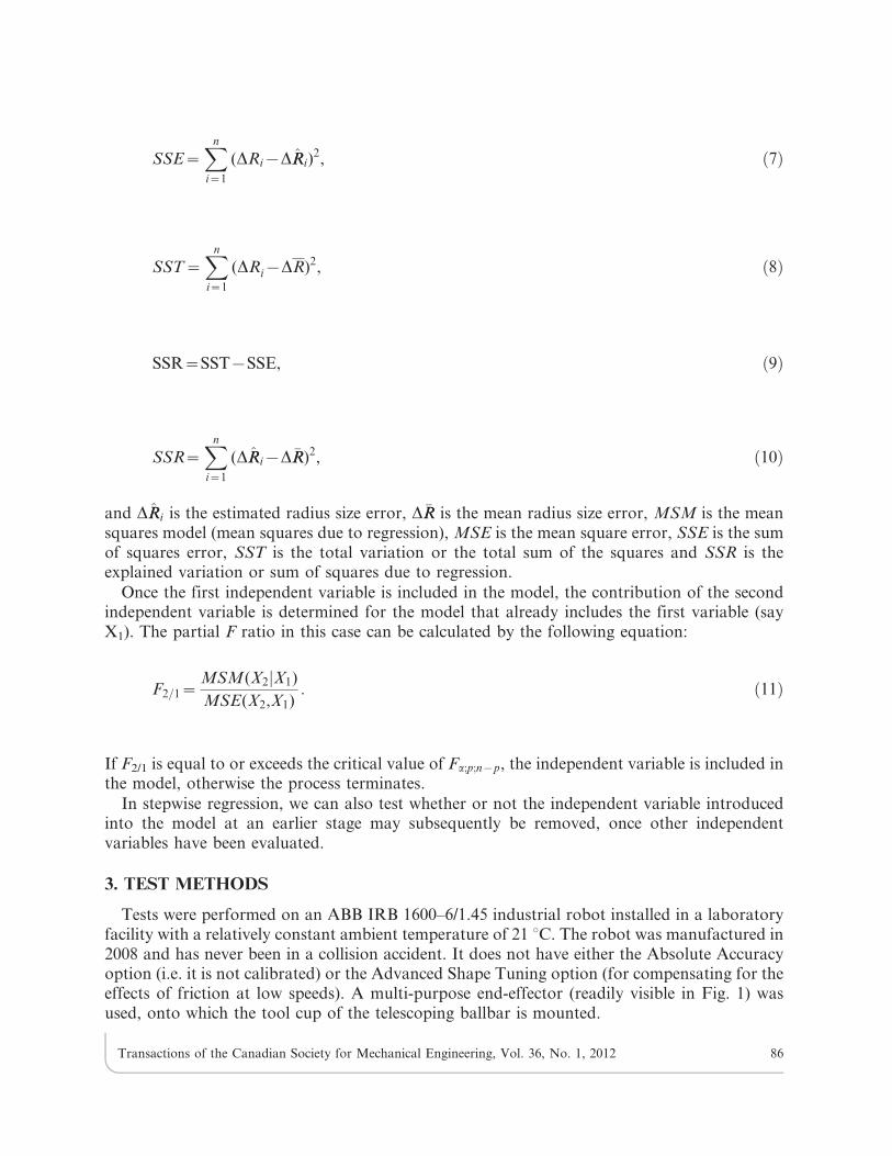
Tests were performed on an ABB IRB 1600–6/1.45 industrial robot installed in a laboratoryfacility with a relatively constant ambient temperature of 21 uC. The robot was manufactured in2008 and has never been in a collision accident. It does not have either the Absolute Accuracyoption (i.e. it is not calibrated) or the Advanced Shape Tuning option (for compensating for theeffects of friction at low speeds). A multi-purpose end-effector (readily visible in Fig. 1) wasused, onto which the tool cup of the telescoping ballbar is mounted.
Transactions of the Canadian Society for Mechanical Engineering, Vol. 36, No. 1, 2012 86
The measurement instrument used in this study is a QC20-W telescopic ballbar by Renishawwith Bluetooth wireless technology. It consists of a wireless telescoping ballbar, ballbarextensions, a tool cup, two measuring balls and a pivot assembly. The tool cup is mounted onthe robot end-effector. The base of the pivot assembly is magnetic, and is solidly attached to aheavy steel table, as shown in Fig. 1. The ballbar sensor accuracy (at 20 uC) is¡0.5 mm, and themeasuring range is a mere ¡1.0 mm (which is probably too small for large, non-calibratedindustrial robots).
Fig. 1. Telescoping ballbar setup for measuring radial errors along a horizontal circular path ofradius 300 mm.
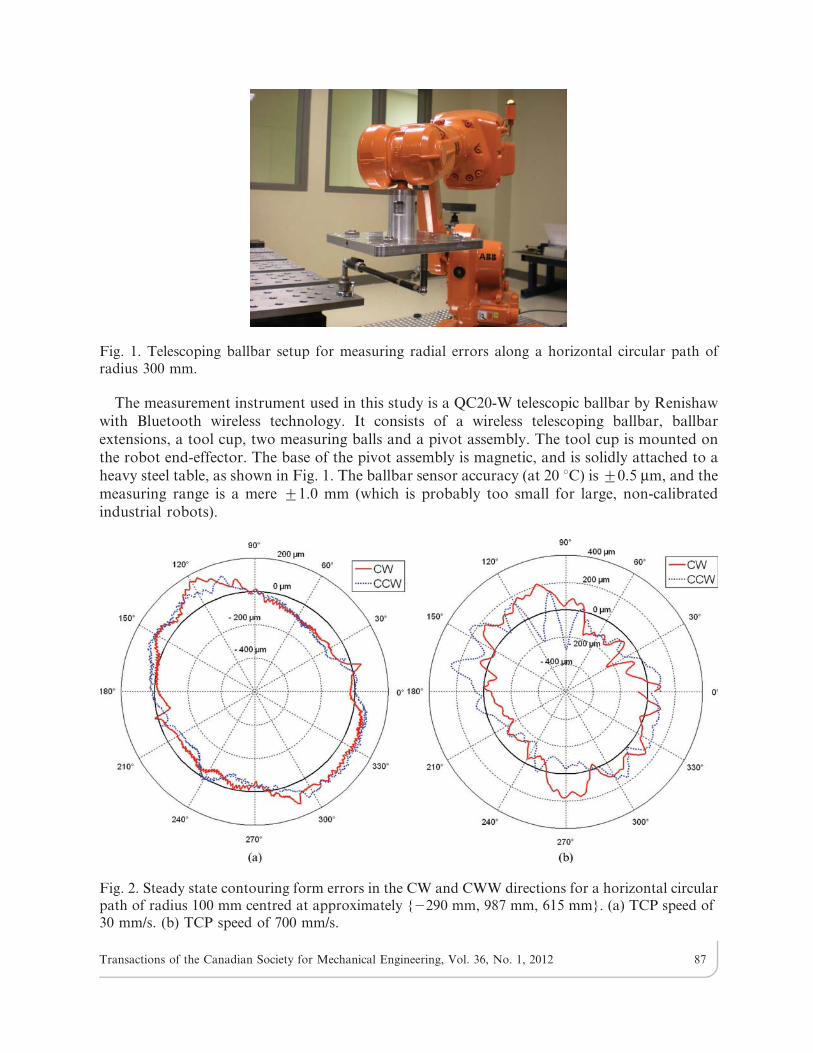
Fig. 2. Steady state contouring form errors in the CW and CWW directions for a horizontal circularpath of radius 100 mm centred at approximately {2290 mm, 987 mm, 615 mm}. (a) TCP speed of30 mm/s. (b) TCP speed of 700 mm/s.
Transactions of the Canadian Society for Mechanical Engineering, Vol. 36, No. 1, 2012 87
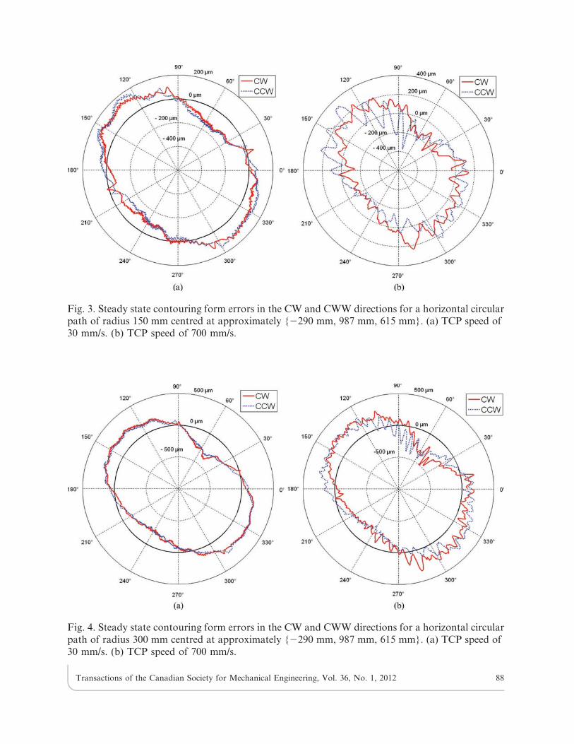
Fig. 3. Steady state contouring form errors in the CW and CWW directions for a horizontal circularpath of radius 150 mm centred at approximately {2290 mm, 987 mm, 615 mm}. (a) TCP speed of30 mm/s. (b) TCP speed of 700 mm/s.
Fig. 4. Steady state contouring form errors in the CW and CWW directions for a horizontal circularpath of radius 300 mm centred at approximately {2290 mm, 987 mm, 615 mm}. (a) TCP speed of30 mm/s. (b) TCP speed of 700 mm/s.
Transactions of the Canadian Society for Mechanical Engineering, Vol. 36, No. 1, 2012 88
An end-effector, weighing approximately 2 kg, was used in all the ballbar tests. Circulartests were performed in the clockwise (CW) and counter-clockwise (CCW) directions at radiiof 100 mm, 150 mm and 300 mm, and at a constant TCP speed, ranging from 20 mm/s to700 mm/s. The coordinates of the measurement point (i.e. the centre of the tool cup) withrespect to the robot flange reference frame is approximately {0 mm, 65 mm, 149 mm}. Toeliminate the effect of not knowing the coordinates of the measurement point precisely, the end-effector is kept at a constant orientation along each circular path.
As the robot runs the ballbar through a sequence of programmed routines, a precisiontransducer tracks the robot’s movement. Renishaw software converts the data into a polar plotof its true movement. Unfortunately, as mentioned above, the ballbar software was developedto analyze CMMs and machine tool data, not robot data. After the end of the test, the raw dataare saved and then analysed separately.
As usual, before starting a telescoping bar test, the robot is warmed up by repeating theactual circular trajectory for one hour (from a cold start).
4. DATA ANALYSIS
A circular test with the telescopic ballbar returns a series of measurement values in the[21 mm, 1 mm] range, approximately. We then add the nominal radius (i.e. the length of theballbar at which it reads a zero error) to these values to obtain the actual circular path (in aCartesian reference frame) and fit a least-squares circle, in order to estimate the actual centre ofthe circular path (which is usually offset by several tens of microns with respect to the taughtcentre position). A circle of nominal radius is then constructed at the least squares circle centre,and errors are considered with respect to this nominal circle. The radius size error is defined as
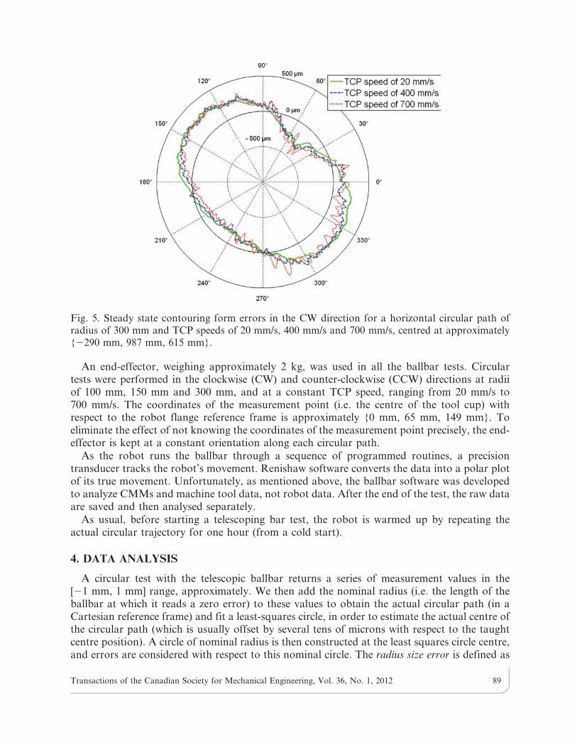
Fig. 5. Steady state contouring form errors in the CW direction for a horizontal circular path ofradius of 300 mm and TCP speeds of 20 mm/s, 400 mm/s and 700 mm/s, centred at approximately{2290 mm, 987 mm, 615 mm}.
Transactions of the Canadian Society for Mechanical Engineering, Vol. 36, No. 1, 2012 89
the radius of the least-squares circle minus the nominal radius. Out-of-roundness is defined asthe difference between the largest and the smallest radial distance from the centre of the least-squares circle to the actual circular path.
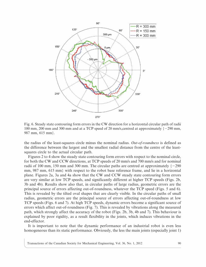
Figures 2 to 4 show the steady state contouring form errors with respect to the nominal circle,for both the CW and CCW directions, at TCP speeds of 20 mm/s and 700 mm/s and for nominalradii of 100 mm, 150 mm and 300 mm. The circular paths are centred at approximately {2290mm, 987 mm, 615 mm} with respect to the robot base reference frame, and lie in a horizontalplane. Figures 2a, 3a and 4a show that the CW and CCW steady state contouring form errorsare very similar at low TCP speeds, and significantly different at higher TCP speeds (Figs. 2b,3b and 4b). Results show also that, in circular paths of large radius, geometric errors are theprincipal source of errors affecting out-of-roundness, whatever the TCP speed (Figs. 5 and 6).This is revealed by the tilted oval shapes that are clearly visible. In the circular paths of smallradius, geometric errors are the principal source of errors affecting out-of-roundness at lowTCP speeds (Figs. 6 and 7). At high TCP speeds, dynamic errors become a significant source oferrors which affect out-of-roundness (Fig. 7). This is revealed by vibrations along the measuredpath, which strongly affect the accuracy of the robot (Figs. 2b, 3b, 4b and 7). This behaviour isexplained by poor rigidity, as a result flexibility in the joints, which induces vibrations in theend-effector.
It is important to note that the dynamic performance of an industrial robot is even lesshomogeneous than its static performance. Obviously, the less the main joints (especially joint 1)
Fig. 6. Steady state contouring form errors in the CW direction for a horizontal circular path of radii100 mm, 200 mm and 300 mm and at a TCP speed of 20 mm/s,centred at approximately {2290 mm,987 mm, 615 mm}.
Transactions of the Canadian Society for Mechanical Engineering, Vol. 36, No. 1, 2012 90
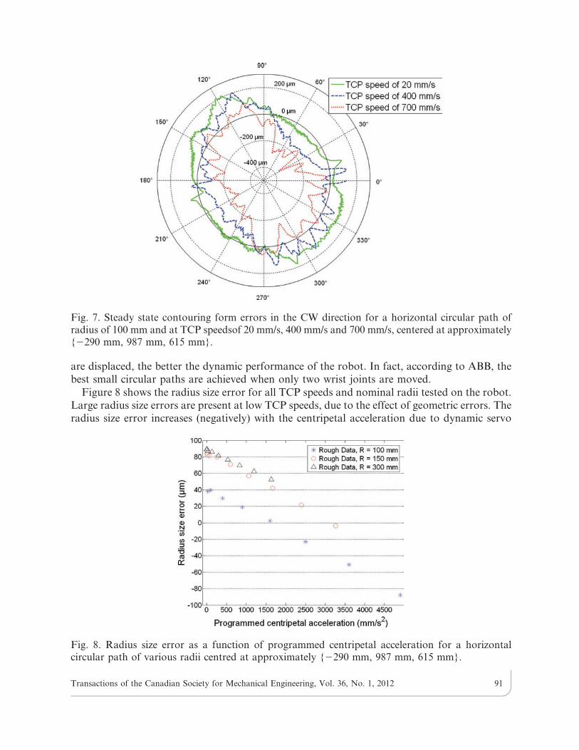
are displaced, the better the dynamic performance of the robot. In fact, according to ABB, thebest small circular paths are achieved when only two wrist joints are moved.
Figure 8 shows the radius size error for all TCP speeds and nominal radii tested on the robot.Large radius size errors are present at low TCP speeds, due to the effect of geometric errors. Theradius size error increases (negatively) with the centripetal acceleration due to dynamic servo
Fig. 7. Steady state contouring form errors in the CW direction for a horizontal circular path ofradius of 100 mm and at TCP speedsof 20 mm/s, 400 mm/s and 700 mm/s, centered at approximately{2290 mm, 987 mm, 615 mm}.
Fig. 8. Radius size error as a function of programmed centripetal acceleration for a horizontalcircular path of various radii centred at approximately {2290 mm, 987 mm, 615 mm}.
Transactions of the Canadian Society for Mechanical Engineering, Vol. 36, No. 1, 2012 91
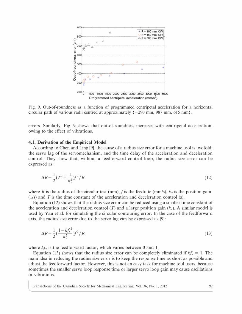
errors. Similarly, Fig. 9 shows that out-of-roundness increases with centripetal acceleration,owing to the effect of vibrations.
4.1. Derivation of the Empirical ModelAccording to Chen and Ling [9], the cause of a radius size error for a machine tool is twofold:
the servo lag of the servomechanism, and the time delay of the acceleration and decelerationcontrol. They show that, without a feedforward control loop, the radius size error can beexpressed as:
DR~1
2(T2z
1
k2v)f 2
�R ð12Þ
where R is the radius of the circular test (mm), f is the feedrate (mm/s), kn is the position gain(1/s) and T is the time constant of the acceleration and deceleration control (s).
Equation (12) shows that the radius size error can be reduced using a smaller time constant ofthe acceleration and deceleration control (T) and a large position gain (kn). A similar model isused by Yau et al. for simulating the circular contouring error. In the case of the feedforwardaxis, the radius size error due to the servo lag can be expressed as [9]:
DR~1
2(1{kfv
2
k2v)f 2
�R ð13Þ
where kfn is the feedforward factor, which varies between 0 and 1.
Equation (13) shows that the radius size error can be completely eliminated if kfn 5 1. Themain idea in reducing the radius size error is to keep the response time as short as possible andadjust the feedforward factor. However, this is not an easy task for machine tool users, becausesometimes the smaller servo loop response time or larger servo loop gain may cause oscillationsor vibrations.
Fig. 9. Out-of-roundness as a function of programmed centripetal acceleration for a horizontalcircular path of various radii centred at approximately {2290 mm, 987 mm, 615 mm}.
Transactions of the Canadian Society for Mechanical Engineering, Vol. 36, No. 1, 2012 92
The constant parameters in brackets in Eqs. (12) and (13) become machine tool constantsonce they have been determined. Since they do not change during machining, Eqs. (12) and (13)can be further rearranged as:
DR~Kf 2
R: ð14Þ
For our industrial robot, our results show that Eq. (14) is not adequate. However, statisticaltests show that the servo contouring error for the industrial robot is in good agreement with thefollowing equation:
DR~b1f 2
Rzb2
f 4
R3ð15Þ
where b1 and b2 are robot constants, f2�R is the centripetal acceleration, R is the programmed
radius and f is the programmed TCP speed.Supposing that X1~f 2
�R and X2~f 4
�R3, Eq. (15) can be written as follows:
DR~b1X1zb2X2: ð16Þ
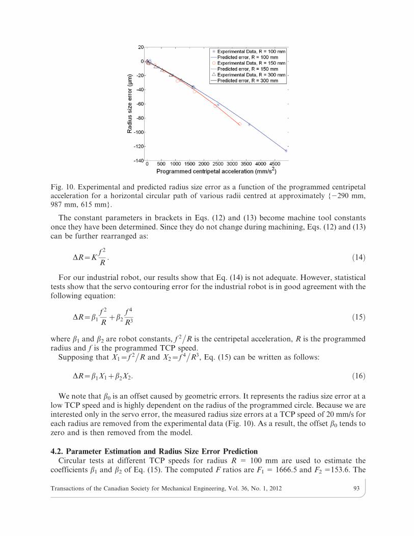
We note that b0 is an offset caused by geometric errors. It represents the radius size error at alow TCP speed and is highly dependent on the radius of the programmed circle. Because we areinterested only in the servo error, the measured radius size errors at a TCP speed of 20 mm/s foreach radius are removed from the experimental data (Fig. 10). As a result, the offset b0 tends tozero and is then removed from the model.
4.2. Parameter Estimation and Radius Size Error PredictionCircular tests at different TCP speeds for radius R 5 100 mm are used to estimate the
coefficients b1 and b2 of Eq. (15). The computed F ratios are F1 5 1666.5 and F2 5153.6. The
Fig. 10. Experimental and predicted radius size error as a function of the programmed centripetalacceleration for a horizontal circular path of various radii centred at approximately {2290 mm,987 mm, 615 mm}.
Transactions of the Canadian Society for Mechanical Engineering, Vol. 36, No. 1, 2012 93
first independent variable to be included in the model is the variable X1, because F1 is largerthan F2 and F1 .F0:05;1;24~4:26. In the second stage, the contribution of the secondindependent variable X2 is determined for the model that already includes the variable X1. Apartial F ratio has to be computed for this variable based on Eq. (17):
F2,1~MSM(X2jX1)
MSE(X2,X1), ð17Þ
where
MSM(X2jX1)~SSR(X2jX1)
p, ð18Þ
SSR(X2jX1)~SSR(X1,X2){SSR(X1): ð19Þ
In the above equations, SSR(X1,X2) represents the sum of squares regression when both X1
and X2 are included in the model, SSR(X2jX1) represents the additional contribution when X2 is
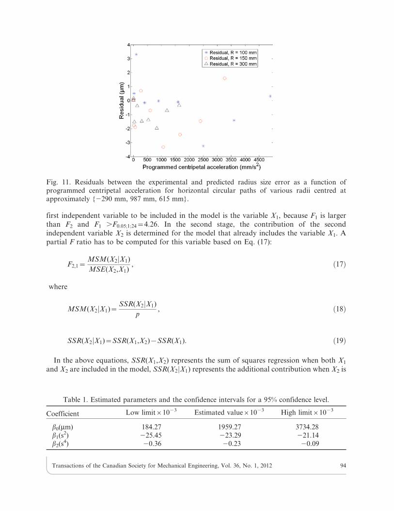
Fig. 11. Residuals between the experimental and predicted radius size error as a function ofprogrammed centripetal acceleration for horizontal circular paths of various radii centred atapproximately {2290 mm, 987 mm, 615 mm}.
Table 1. Estimated parameters and the confidence intervals for a 95% confidence level.
Coefficient Low limit61023 Estimated value61023 High limit61023
b0(mm) 184.27 1959.27 3734.28b1(s
2) 225.45 223.29 221.14b2(s
4) 20.36 20.23 20.09
Transactions of the Canadian Society for Mechanical Engineering, Vol. 36, No. 1, 2012 94
included, given that X1 is already in the model, and SSR(X1) represents the contribution whenonly X1 is included in the model.
Results show that F2/1 5 21.4. Since the F2/1 value is clearly greater than the critical Fishervalue of F0:05;1;24~4:26 at the 0.05 level of significance, then X2 is included in the model.
To measure the overall quality of the estimation and the uncertainty associated with a specificestimate, a calculation of the confidence region is required. This can be achieved based on Eq.(20). Every estimated value will be in this region, with a confidence level of 1006 (12a)%(a being the significance level) [16].
bbj{t a2p{n{p
ffiffiffiffiffiffiffiffiffiffiffis2Cjj
qƒbjƒbbjzt a
2p{n{p
ffiffiffiffiffiffiffiffiffiffiffis2Cjj
qð20Þ
where bb is normally distributed with mean vector b and covariance matrix s2(JTJ)21, Cjj is thediagonal element of (JTJ)21, s2 is the error variance, n is the number of observations and p isthe number of unknowns. The error variance is defined as
s2~DrTDr{bbTJTDr
n{p: ð21Þ
Table 1 shows the range of values calculated using Eq. (20) for 95% confidence levels.
The estimated coefficients and the statistical model that has been developed are then used topredict the radius size error using experimental data with different radii from those used foridentification. As shown in Fig. 10, good agreement was obtained. Furthermore, a closer lookat the residuals between the real and predicted radius illustrated in Fig. 11 shows that the modelwas used successfully to predict the radius size error, as the residuals are smaller than 4 mm.
5. CONCLUSION
Circular tests performed on an ABB IRB 1600-6/1.45 industrial robot show that servodynamic errors have a significant impact on contouring errors, causing out-of-roundness andpotentially large radius size errors. Comparison of the telescoping ballbar tests performed atdifferent TCP speeds shows that the geometric errors are dominant at low TCP speeds and havea significant impact on circular contouring errors. The dynamic errors are present as vibrations,and are dominant at high TCP speeds for small radii, reaching 25% of the total error at a TCPspeed of 700 mm/s. Results also show that the tested robot exhibits significant radius size errors.An approach for the modelling and prediction of the radius size error is presented based onexperimental data and statistical tests. The developed model was fitted using experimental data,and then its performance was checked by comparing the model predictions to additional sets ofdata which are different from those used for identification. Results show that the model wasable to predict 98% to 99% of the radius size error.
REFERENCES
1. Brogardh, T., ‘‘Robot control overview: An industrial perspective,’’ Modeling, Identification and
Control, Vol. 30, No. 3, pp. 167–180, 2009.
Transactions of the Canadian Society for Mechanical Engineering, Vol. 36, No. 1, 2012 95
2. Damak, M., Grosbois, J. and De Smet, P., ‘‘Vision robot based absolute accuracymeasurement-calibration and uncertainty evaluation,’’ The 35th International Symposium onRobotics, Paris-Nord Villepinte, France, 2004.
3. Hayati, S., Tso, K. and Roston, G., ‘‘Robot geometry calibration,’’IEEE International
Conference on Robotics and Automation, Philadelphia, PA, USA, Vol. 942, pp. 947–951, 1988.4. Kataoka, H., Miyazaki, T., Ohishi, K., Katsura, S. and Tungpataratanawong, S., ‘‘Tracking
control for industrial robot using notch filtering system with little phase error,’’ ElectricalEngineering in Japan, Vol. 175, No. 1, pp. 793–801, 2011.
5. Olabi, A., Bearee, R., Gibaru, O. and Damak, M., ‘‘Feedrate planning for machining withindustrial six-axis robots,’’ Control Engineering Practice, Vol. 18, No. 5, pp. 471–482, 2010.
6. Lischinsky, P., Canudas-de-Wit, C. and Morel, G., ‘‘Friction Compensation of a SchillingHydraulic Robot,’’ IEEE International Conference on Control Applications, Hartford, CT, USA,October 5–7, pp. 294–299, 1997.
7. Slamani, M., Mayer, R., Balazinski, M. and Engin, S., ‘‘Identification and compensation ofdynamic scale mismatches in a high-speed end mill boring trajectory on CNC machines,’’Journal of Manufacturing Science and Engineering, Vol. 132, No. 3, pp. 0345011–0345016, 2010.
8. Yau, H.T., Ting, J.Y. and Chuang, C.M., ‘‘NC simulation with dynamic errors due to high-speed motion,’’ The International Journal of Advanced Manufacturing Technology, Vol. 23,No. 7–8, pp. 577–585, 2004.
9. Chen, J.S. and Ling, C.C., ‘‘Improving the machine accuracy through machine tool metrologyand error correction,’’International Journal of Advanced Manufacturing Technology, Vol. 11,No. 3, pp. 198–205, 1996.
10. Ota, H., Shibukawa, T. and Uchiyama, M., ‘‘Forward kinematic calibration method for parallelmechanism using pose data measured by a double ball bar system,’’ Proceedings of the Year
2000 Parallel Kinematic Machines International Conference, pp. 57–62, 2000.11. Vira, N. and Lau, K., ‘‘An extensible ball bar for evaluation of robots’ positioning
performance,’’ Journal of Robotic Systems, Vol. 4, No. 6, pp. 799–814, 1987.12. Karlsson, B. and Brogardh, T., ‘‘A new calibration method for industrial robots,’’ Robotica,
Vol. 19, No. 6, 2001.13. Oh, Y.T., ‘‘Influence of the joint angular characteristics on the accuracy of industrial robots,’’
Industrial Robot: An International Journal, Vol. 38, No. 4, pp. 406–418, 2011.14. Lei, W. T., Paung, I. M. and Yu, C.-C. ‘‘Total ballbar dynamic tests for five-axis CNC machine
tools,’’ International Journal of Machine Tools & Manufacture, Vol. 49, No. 6, pp. 488–499,2009.
15. Zargarbashi, S.H.H. and Mayer, J.R.R. ‘‘Assessment of machine tool trunnion axis motionerror, using magnetic double ball bar,’’ International Journal of Machine Tools & Manufacture,Vol. 46, No. 14, pp. 1823–1834, 2006.
16. Berenson, M.L., Levine, D.M. and Goldstein, M., Intermediate Statistical Methods andApplications: A Computer Package Approach, Prentice-Hall, Englewood Cliffs, 1983.
Transactions of the Canadian Society for Mechanical Engineering, Vol. 36, No. 1, 2012 96