Heat Load Calculation with Duct Design of a Multi Storeyed Residential Building

International Journal of Technical Innovation in Modern Engineering & Science (IJTIMES)
Impact Factor: 5.22 (SJIF-2017), e-ISSN: 2455-2585 Volume 4, Issue 12, December-2018
IJTIMES-2018@All rights reserved 162
EFFECT OF FLOATING COLUMNS ON MULTI-STOREYED BUILDINGS
1 R.S.S. Babitha Sri ,2 Dr. Shaik Yajdani
1M.Tech, Department of Civil Engineering, Andhra University College of Engineering, Visakhapatnam, India. 2 Associate Professor, Department of Civil Engineering, Andhra University College of Engineering, Visakhapatnam,
India.
Abstract: — The columns which are supported on a beam instead of the rigid foundation are called as the floating
columns. Floating columns are adopted to fulfil the room sizes criteria of architects. In the recent days, lots of multi-
storeyed buildings are constructed with floating column for getting more space at parking areas for movement and for
aesthetic point of view. But, such buildings are highly gets damaged during earthquake in highly seismic zone as
compared to regular building. Structure with the floating column must be sound enough to resist earthquake forces.
The earthquake forces developed at the different floor levels in the building need to be brought down along the height
to the ground by the shortest path, if any deviation or discontinuity such as floating columns results in poor
performance of the building. In this study, the effect of floating columns on RC frame G+9 structure has been studied
for zone III. This work is done to study the response of RC frame building with floating columns under earthquake
loading. For all the models of the building, response spectrum analysis is carried out. The work includes analysis of
the structure by using ETABS software. The comparative results for the building models have been studied for various
parameters such as base shear, storey shear, storey drift, storey displacement, stiffness, beam forces, column forces
and time period.
Keywords— Floating column, RC frame, Response spectrum analysis, ETABS etc.
1. INTRODUCTION
Earthquakes perhaps the most unpredictable and devastating of all the natural disasters. They cause great destruction in
terms of human casualties, and also have a tremendous economic impact on the affected area. The concern about seismic
hazards has led to the awareness and demand for the structures designed to withstand seismic forces. To make the
buildings and structures safe in earthquake prone areas lies on the designers, architects, and engineers who conceptualize
these structures. Many urban multistorey buildings in India today have open first storey as an unavoidable feature. This is
primarily being adopted to accommodate parking or reception lobbies in the first storey. The total seismic base shear
experienced by a building during an earthquake is dependent on its natural period and the seismic force distribution is
dependent on the distribution of stiffness and mass along the height. The behaviour of a building during earthquakes
depends critically on its overall size, shape and geometry, in addition to how the earthquake forces are carried to the
ground.
The floating column which is a vertical element, its lower level rests on a beam which is a horizontal member. This
horizontal member in turn transfer the load to other columns below it. The load from the floating column act as a
concentrated load on the transfer beam. The floating columns are implemented, especially above the base floor, so that
added open space is accessible for assembly hall or parking purpose. Floating columns are usually adopted above the
ground story level. So that, maximum space is made available in the ground floor which is essentially required in the
apartments, mall or other commercial buildings where parking is a major problem.
2. LITERATURE REVIEW
Nikhil Bandawal (2014) focused on the various types of irregularities like floating columns at various levels and various
levels and locations. Earthquake load as specified in IS 1893 (part 1): 2002 are considered in the analysis of building . A
G+06 storied building with different architectural complexities such as External floating columns, Internal floating
columns and combination of Internal and External floating columns is analysed for various earthquake zones. This
building is design and analyse with the help of STAAD-Pro software. It is concluded that external floating columns may
increase displacements at various nodes, external and internal floating columns and Internal floating columns may
increase axial force Fx and shear in z direction (Fz) at all floors. internal and external floating columns increases the Mx
and Mz values at all floors for all zones.
Er. Ashfi Rahman (2015), has analysed a multi-storey building with and without floating columns by using response
spectrum analysis. Different cases of the building are studied by varying the location of floating columns floor wise and
within the floor. The structural response of the building models with respect to fundamental time period, Spectral
acceleration, Base shear, Storey drift and Storey displacements is investigated. The analysis is carried out using software
STAAD Pro V8i software. It was observed that in building with floating columns there is an increase in fundamental
time period in both X-direction as well as Z-direction as compared to building without floating columns, By introduction
of floating columns in a building base shear and spectral acceleration decreases. Thus, it has this technical and functional
advantage over conventional construction.
International Journal of Technical Innovation in Modern Engineering & Science (IJTIMES)
Volume 4, Issue 12, December-2018, e-ISSN: 2455-2585, Impact Factor: 5.22 (SJIF-2017)
IJTIMES-2018@All rights reserved 163
S.B Waykule and Dr. C.P. (2016) studied about analysis of G+5 Building with and without floating column in highly
seismic zone v. Two models are created such as floating column at 1st and without floating column building. Linear static
and time history analysis are carried out of all the two models and comparison of seismic response parameter such as
time period, base shear, storey displacement, storey drift and dynamic response are done by varying the location of
floating column floor wise by using linear static and time history analysis. It was observed that in building with floating
column has more time period, less base shear, more displacement, more storey drift compared to building without
floating column.
Rupali Goud (2017) compared the response of two RC frame buildings with and without floating columns under
earthquake loading and under normal loading. The buildings were modified in four different ways. The effect of
earthquake forces on these models building models for various parameters were carried out with the help of response
spectrum analysis using Staad-Pro. Parameters such as storey drift, storey displacement and amount of steel required
were compared with the results of normal RC building.
3. OBJECTIVES OF WORK
The objective of this study is to carry out the analysis of the multi-storeyed building against earthquake load as per Indian
standard code of practice IS 1893(Part 1):2002.
1. To check the behaviour of RC framed building with and without floating columns under seismic load.
2. Determination of seismic response of all the models by using response spectrum analysis for zone III earthquake
loading. The base of the building frame is assumed to be fixed.
3. To study the response of base shear, storey drift, storey displacement, storey stiffness, storey shears and time period of
the models with and without floating columns.
4. To determine the affect of shear force and moment in columns and beams among the RC framed models with and
without floating column.
4. MODELLING OF THE BUILDING
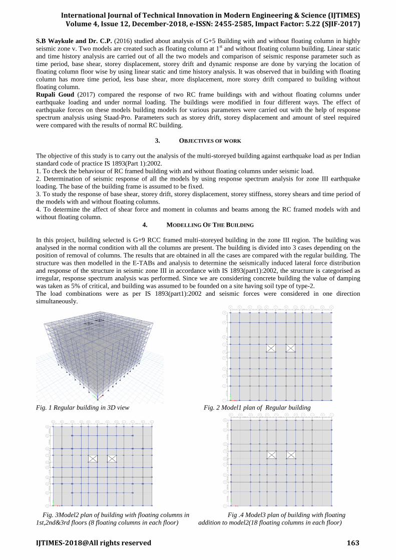
In this project, building selected is G+9 RCC framed multi-storeyed building in the zone III region. The building was
analysed in the normal condition with all the columns are present. The building is divided into 3 cases depending on the
position of removal of columns. The results that are obtained in all the cases are compared with the regular building. The
structure was then modelled in the E-TABs and analysis to determine the seismically induced lateral force distribution
and response of the structure in seismic zone III in accordance with IS 1893(part1):2002, the structure is categorised as
irregular, response spectrum analysis was performed. Since we are considering concrete building the value of damping
was taken as 5% of critical, and building was assumed to be founded on a site having soil type of type-2.
The load combinations were as per IS 1893(part1):2002 and seismic forces were considered in one direction
simultaneously.
Fig. 1 Regular building in 3D view Fig. 2 Model1 plan of Regular building
Fig. 3Model2 plan of building with floating columns in Fig .4 Model3 plan of building with floating
1st,2nd&3rd floors (8 floating columns in each floor) addition to model2(18 floating columns in each floor)

International Journal of Technical Innovation in Modern Engineering & Science (IJTIMES)
Volume 4, Issue 12, December-2018, e-ISSN: 2455-2585, Impact Factor: 5.22 (SJIF-2017)
IJTIMES-2018@All rights reserved 164
Table1. Specifications of the regular building
Parameters Regular building
Floor Height 3.0m
Height of the Building 30m
Seismic zone Zone III
Soil Type Medium
Thickness of slab 150mm
Beam Dimensions 230mmX370mm,
300mmX450mm
Column dimensions 300mmX450mm,
370mmX600mm,
300mmX530mm,
Grade of Concrete M30
5. MODELLING OF THE BUILDING
Analysis is carried out for G+9 building by considering all earthquake load combination. The parameters used for
comparison are base shear, storey shear, column forces, storey drift, storey maximum displacement, storey stiffness
between regular frame and floating columns frame.
5.1 Base Shear:
Base shear is the horizontal reaction at the base against horizontal earthquake load. This base shear is acting at the base
or supports of the structure or wherever structure is fixed and it depends on the seismic mass and stiffness of building.
Table2. Base shear along x-direction Table3. Base shear along y-direction
Base Shear VB (KN)
Direction Model 1 Model 2 Model 3
X 2517.24 2534.07 2559.99
Fig.5 Comparison of base shear in x direction Fig.6 Comparison of base shear in y direction
5.2 Storey Shear:
The forces which are induced at every storey during earthquake are known as storey forces. For a building, storey forces
goes on increasing for lower stories and it will be maximum for bottom storey.
Base Shear VB (kN)
Direction Model 1 Model 2 Model 3
Y 1916.58 1984.38 1852.88
International Journal of Technical Innovation in Modern Engineering & Science (IJTIMES)
Volume 4, Issue 12, December-2018, e-ISSN: 2455-2585, Impact Factor: 5.22 (SJIF-2017)
IJTIMES-2018@All rights reserved 165
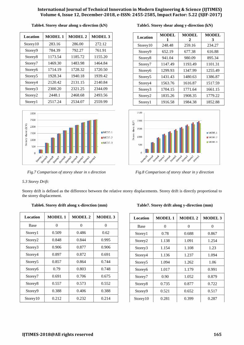
Table4. Storey shear along x-direction (kN) Table5. Storey shear along y-direction (kN)
Location MODEL 1 MODEL 2 MODEL 3
Storey10 283.16 286.00 272.12
Storey9 784.39 792.27 761.91
Storey8 1173.54 1185.72 1155.20
Storey7 1469.30 1483.98 1464.84
Storey6 1714.19 1728.32 1720.50
Storey5 1928.34 1940.18 1939.42
Storey4 2120.42 2131.15 2140.84
Storey3 2300.20 2321.25 2344.09
Storey2 2448.1 2468.68 2493.56
Storey1 2517.24 2534.07 2559.99
Fig.7 Comparison of storey shear in x direction Fig.8 Comparison of storey shear in y direction
5.3 Storey Drift:
Storey drift is defined as the difference between the relative storey displacements. Storey drift is directly proportional to
the storey displacement.
Table6. Storey drift along x-direction (mm) Table7. Storey drift along y-direction (mm)
Location MODEL 1 MODEL 2 MODEL 3
Base 0 0 0
Storey1 0.509 0.486 0.62
Storey2 0.848 0.844 0.995
Storey3 0.906 0.877 0.906
Storey4 0.897 0.872 0.691
Storey5 0.857 0.864 0.744
Storey6 0.79 0.803 0.748
Storey7 0.691 0.706 0.675
Storey8 0.557 0.573 0.552
Storey9 0.388 0.406 0.388
Storey10 0.212 0.232 0.214
Location MODEL
1
MODEL
2
MODEL
3
Storey10 248.48 259.16 234.27
Storey9 652.19 677.38 616.88
Storey8 941.04 980.09 895.34
Storey7 1147.49 1193.49 1101.31
Storey6 1299.93 1347.99 1255.49
Storey5 1431.43 1480.63 1386.87
Storey4 1563.76 1616.87 1517.59
Storey3 1704.15 1771.64 1661.15
Storey2 1835.26 1908.35 1779.22
Storey1 1916.58 1984.38 1852.88
Location MODEL 1 MODEL 2 MODEL 3
Base 0 0 0
Storey1 0.78 0.688 0.867
Storey2 1.138 1.091 1.254
Storey3 1.154 1.108 1.23
Storey4 1.136 1.237 1.094
Storey5 1.094 1.262 1.06
Storey6 1.017 1.179 0.991
Storey7 0.90 1.052 0.879
Storey8 0.735 0.877 0.722
Storey9 0.521 0.652 0.517
Storey10 0.281 0.399 0.287

International Journal of Technical Innovation in Modern Engineering & Science (IJTIMES)
Volume 4, Issue 12, December-2018, e-ISSN: 2455-2585, Impact Factor: 5.22 (SJIF-2017)
IJTIMES-2018@All rights reserved 166
Fig.9 Comparison of storey drift in x direction Fig.10 Comparison of storey drift in y direction
5.4 Storey Displacement:
Storey displacement is the lateral movement of the structure caused by lateral force. The deflected shape of a structure is
the most important and most clearly visible point of comparison for any structure. No other parameter of comparison can
give a better idea of behaviour of the structure than comparison of storey displacement.
The reason for high storey displacements in buildings with floating columns is that the stiffness of the building decreases
due to the presence of floating columns. Due to discontinuity of stiffness, the flexibility increases and strength decreases
resulting in high displacements. Storey displacement is proportional to the storey stiffness, as storey stiffness increases
storey displacement decreases and viceversa.
Table8. Storey displacement along x-direction (mm) Table9. Storey displacement along y-direction (mm)
Location MODEL 1 MODEL 2 MODEL 3
Base 0 0 0
Storey1 1.5 1.5 1.8
Storey2 4.1 4 4.8
Storey3 6.8 6.6 7.5
Storey4 9.5 9.2 9.6
Storey5 12 11.8 11.8
Storey6 14.4 14.2 14.1
Storey7 16.5 16.3 16.1
Storey8 18.2 18 17.8
Storey9 19.3 19.2 18.9
Storey10 20 19.9 19.6
Fig.11 Comparison of storey displacement in x direction Fig.12 Comparison of storey displacement in y direction
Location MODEL
1
MODEL
2
MODEL
3
Base 0 0 0
Storey1 2.3 2.1 2.6
Storey2 5.8 5.3 6.4
Storey3 9.2 8.6 10
Storey4 12.6 12.4 13.2
Storey5 15.8 16.1 16.4
Storey6 18.8 19.7 19.3
Storey7 21.5 22.8 22
Storey8 23.7 25.5 24.1
Storey9 25.2 27.4 25.7
Storey10 26.1 28.6 26.5

International Journal of Technical Innovation in Modern Engineering & Science (IJTIMES)
Volume 4, Issue 12, December-2018, e-ISSN: 2455-2585, Impact Factor: 5.22 (SJIF-2017)
IJTIMES-2018@All rights reserved 167
5.5 Storey stiffness:
Table10. Storey stiffness along x-direction (kN/m) Table11. Storey stiffness along y-direction (kN/m)
Location MODEL 1 MODEL 2 MODEL 3
Storey10 879213.14 831007.071 848522.092
Storey9 1296710.414 1258265.026 1275920.02
Storey8 1341486.906 1313848.945 1346732.777
Storey7 1345024.01 1323057.682 1379927.452
Storey6 1348561.408 1331279.252 1422611.065
Storey5 1355057 1348193.291 1557803.423
Storey4 1365511.318 1409959.279 1767636.017
Storey3 1395609.878 1449401.423 1381259.204
Storey2 1515562.865 1536138.151 1282133.358
Storey1 2529635.386 2673799.241 2104904.983
Fig.13 Comparison of storey stiffness in x direction Fig.14 Comparison of storey stiffness in y direction
5.6 Time Period:
Fundamental time period is the time taken by the building to undergo a cycle of to and fro movement. The introduction
of floating columns decreases the time period due to increase in the stiffness of structure.
Table 12. Comparison of Time period (sec)
Fig.14 Comparison of Time period in sec.
5.7 Beam forces:
The following were the bending moment values of the continuous beam (B23,B24….B30) of the storey4 for all the
models.
Location MODEL 1 MODEL 2 MODEL 3
Storey10 605780.197 603382.904 584536.691
Storey9 793332.848 790141.235 778771.77
Storey8 804578.358 803292.168 794516.331
Storey7 806694.433 805770.046 800143.51
Storey6 807630.126 807450.308 803445.136
Storey5 810459.379 816042.087 811303.616
Storey4 815464.543 890583.597 821055.607
Storey3 825514.483 949217.829 743700.85
Storey2 859291.985 926786.632 747050.873
Storey1 1261087.6 1469828.255 1087029.956
Mode MODEL 1 MODEL 2 MODEL 3
1 1.724 1.664 1.786
2 1.33 1.318 1.372
3 1.308 1.301 1.307
4 0.566 0.557 0.582
5 0.433 0.436 0.45
6 0.424 0.424 0.434
7 0.33 0.323 0.333
8 0.249 0.248 0.25
9 0.241 0.239 0.237
10 0.23 0.221 0.232
11 0.174 0.168 0.178
12 0.17 0.166 0.17
International Journal of Technical Innovation in Modern Engineering & Science (IJTIMES)
Volume 4, Issue 12, December-2018, e-ISSN: 2455-2585, Impact Factor: 5.22 (SJIF-2017)
IJTIMES-2018@All rights reserved 168
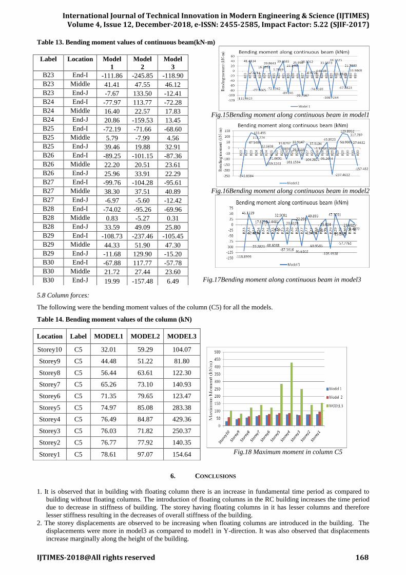
Table 13. Bending moment values of continuous beam(kN-m)
Fig.15Bending moment along continuous beam in model1
Fig.16Bending moment along continuous beam in model2
Fig.17Bending moment along continuous beam in model3
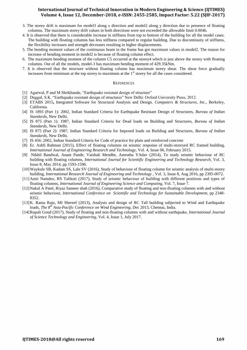
5.8 Column forces:
The following were the bending moment values of the column (C5) for all the models.
Table 14. Bending moment values of the column (kN)
Fig.18 Maximum moment in column C5
6. CONCLUSIONS
1. It is observed that in building with floating column there is an increase in fundamental time period as compared to
building without floating columns. The introduction of floating columns in the RC building increases the time period
due to decrease in stiffness of building. The storey having floating columns in it has lesser columns and therefore
lesser stiffness resulting in the decreases of overall stiffness of the building.
2. The storey displacements are observed to be increasing when floating columns are introduced in the building. The
displacements were more in model3 as compared to model1 in Y-direction. It was also observed that displacements
increase marginally along the height of the building.
Label Location Model
1
Model
2
Model
3
B23 End-I -111.86 -245.85 -118.90
B23 Middle 41.41 47.55 46.12
B23 End-J -7.67 133.50 -12.41
B24 End-I -77.97 113.77 -72.28
B24 Middle 16.40 22.57 17.83
B24 End-J 20.86 -159.53 13.45
B25 End-I -72.19 -71.66 -68.60
B25 Middle 5.79 -7.99 4.56
B25 End-J 39.46 19.88 32.91
B26 End-I -89.25 -101.15 -87.36
B26 Middle 22.20 20.51 23.61
B26 End-J 25.96 33.91 22.29
B27 End-I -99.76 -104.28 -95.61
B27 Middle 38.30 37.51 40.89
B27 End-J -6.97 -5.60 -12.42
B28 End-I -74.02 -95.26 -69.96
B28 Middle 0.83 -5.27 0.31
B28 End-J 33.59 49.09 25.80
B29 End-I -108.73 -237.46 -105.45
B29 Middle 44.33 51.90 47.30
B29 End-J -11.68 129.90 -15.20
B30 End-I -67.88 117.77 -57.78
B30 Middle 21.72 27.44 23.60
B30 End-J 19.99 -157.48 6.49
Location Label MODEL1 MODEL2 MODEL3
Storey10 C5 32.01 59.29 104.07
Storey9 C5 44.48 51.22 81.80
Storey8 C5 56.44 63.61 122.30
Storey7 C5 65.26 73.10 140.93
Storey6 C5 71.35 79.65 123.47
Storey5 C5 74.97 85.08 283.38
Storey4 C5 76.49 84.87 429.36
Storey3 C5 76.03 71.82 250.37
Storey2 C5 76.77 77.92 140.35
Storey1 C5 78.61 97.07 154.64
International Journal of Technical Innovation in Modern Engineering & Science (IJTIMES)
Volume 4, Issue 12, December-2018, e-ISSN: 2455-2585, Impact Factor: 5.22 (SJIF-2017)
IJTIMES-2018@All rights reserved 169
3. The storey drift is maximum for model3 along x direction and model2 along y direction due to presence of floating
columns. The maximum storey drift values in both directions were not exceeded the allowable limit 0.004h.
4. It is observed that there is considerable increase in stiffness from top to bottom of the building for all the model cases.
The building with floating columns has less stiffness compared to regular building. Due to discontinuity of stiffness,
the flexibility increases and strength decreases resulting in higher displacements.
5. The bending moment values of the continuous beam in the frame has got maximum values in model2. The reason for
increase of bending moment in model2 is because of floating column effect.
6. The maximum bending moment of the column C5 occurred at the storey4 which is just above the storey with floating
columns. Out of all the models, model-3 has maximum bending moment of 429.35kNm.
7. It is observed that the structure without floating column has maximum storey shear. The shear force gradually
increases from minimum at the top storey to maximum at the 1st storey for all the cases considered.
REFERENCES
[1] Agarwal, P and M Shrikhande, “Earthquake resistant design of structure”
[2] Duggal, S.K. “Earthquake resistant design of structures” New Delhi: Oxford University Press, 2012.
[3] ETABS 2015, Integrated Software for Structural Analysis and Design. Computers & Structures, Inc., Berkeley,
California.
[4] IS 1893 (Part 1): 2002, Indian Standard Criteria for Earthquake Resistant Design of Structures, Bureau of Indian
Standards, New Delhi.
[5] IS 875 (Part 1): 1987, Indian Standard Criteria for Dead loads on Building and Structures, Bureau of Indian
Standards, New Delhi.
[6] IS 875 (Part 2): 1987, Indian Standard Criteria for Imposed loads on Building and Structures, Bureau of Indian
Standards, New Delhi.
[7] IS 456: 2002, Indian Standard Criteria for Code of practice for plain and reinforced concrete
[8] Er. Ashfi Rahman (2015), Effect of floating columns on seismic response of multi-storeyed RC framed building,
International Journal of Engineering Research and Technology, Vol. 4, Issue 06, February 2015.
[9] Nikhil Bandwal, Anant Pande, Vaishali Mendhe, Amrutha YAdav (2014), To study seismic behaviour of RC
building with floating columns, International Journal for Scientific Engineering and Technology Research, Vol. 3,
Issue 8, May 2014, pp 1593-1596.
[10] Waykule SB, Kadam SS, Lale SV (2016), Study of behaviour of floating column for seismic analysis of multi-storey
building, International Research Journal of Engineering and Technology , Vol. 3, Issue 8, Aug 2016, pp 2395-0072.
[11] Amit Namdeo, RS Talikoti (2017), Study of seismic behaviour of building with different positions and types of
floating columns, International Journal of Engineering Science and Computing, Vol. 7, Issue 7.
[12] Nakul A Patel, Riyaz Sameer shah (2016), Comparative study of floating and non-floating columns with and without
seismic behaviour, International Conference on Scientific and Technology for Sustainable Development, pp 2348-
8352.
[13] K. Rama Raju, MI Shereef (2013), Analysis and design of RC Tall building subjected to Wind and Earthquake
loads, The 8th Asia-Pacific Conference on Wind Engineering, Dec 2013, Chennai, India.
[14] Rupali Goud (2017), Study of floating and non-floating columns with and without earthquake, International Journal
of Science Technology and Engineering, Vol. 4, Issue 1, July 2017.