Calcium Aluminate Cement as Dental Restorative. Mechanical ...
Upload
muhammad-javed-iqbalCategory
view
223download
3
A
captissA©
K
1
ptrtpahtmtrisit
f
0d
Materials Science and Engineering B 136 (2007) 140–147
Effect of doping of divalent and trivalent metal ions on the structuraland electrical properties of magnesium aluminate
Muhammad Javed Iqbal ∗, Saima FarooqDepartment of Chemistry, Quaid-i-Azam University, Islamabad 45320, Pakistan
Received 21 July 2006; received in revised form 26 August 2006; accepted 8 September 2006
bstract
Nanosized magnesium aluminate materials doped by divalent cations (Ca2+, Ba2+, Sr2+) and trivalent cations (Cr3+, Mn3+, Fe3+) having nominalompositions Mg1−xMxAl2O4 and MgAl2−xMxO4 (x = 0.02–0.1), respectively, were synthesized by the sol–gel method. The samples were char-cterized by X-ray diffraction (XRD) and dc electrical resistivity measurements. The XRD data showed that all the samples were spinel singlehase cubic closed packed crystalline materials having crystallite sizes between 6 and 35 nm. The lattice constant and X-ray density were foundo be affected by the ionic radii of doped metal cations investigated here. Both the bulk density (db) and X-ray density (dx) of doped materialsncreased whereas the porosity percentage (P) decreased with the increase in the contents of the substituents. The dc-electrical resistivity of all the
amples was measured in temperature range 160–400 ◦C by a two-point probe method and was found to decrease with temperature as expected foremiconductors. It was observed that alkaline earth metal dopants increased the resistivity of MgAl2O4 more than that by transition metal dopants.rhenius activation energy of hopping of electron for all the samples was also calculated.2006 Elsevier B.V. All rights reserved.o-poin
capgictcigabCtp
eywords: Nanomaterials; Magnesium aluminate; dc-Electrical resistivity; Tw
. Introduction
Nanophase materials (<100 nm) exhibit greatly alteredhysicochemical properties compared to their normal bulk coun-erparts [1–3]. Because of their theoretical and technologicalelevance, spinel magnesium aluminates and their related struc-ures have been studied thoroughly. It is a mixed oxide whosehysical properties range between those of magnesium oxidend aluminum oxide. Magnesium aluminate (MgAl2O4) spinelas received a great deal of attention as a technologically impor-ant material on account of its attractive properties such as high
elting point (2135 ◦C), high mechanical strength at elevatedemperatures, high chemical inertness and good thermal shockesistance [4–6]. Therefore, it has been extensively used for var-ous purposes such as refractory material [7], catalyst or catalyst
upport in the field of environmental catalysis [8], active elementn humidity sensors [9] and structural material in fusion reac-ors [10]. It has also been employed as an excellent transparent∗ Corresponding author. Tel.: +92 51 9219811/0642143;ax: +92 51 2873869/271689.
E-mail address: [email protected] (M.J. Iqbal).
2
oM9u
921-5107/$ – see front matter © 2006 Elsevier B.V. All rights reserved.oi:10.1016/j.mseb.2006.09.009
t probe method; X-ray density
eramic material for high-temperature arc-enclosing envelopsnd alkali-metal vapor discharge devices [11]. The physicalroperties of ceramic materials are influenced by the nature ofrains, such as shape, size, orientation, grain boundaries, voids,nhomogeneities, etc. The electronic properties and electricalonductivity of mesoscopically small crystals change comparedo their bulk counterparts owing to their small grain sizes. Thehange also depends on the large percentage of their atomsn grain boundary environments and the interactions betweenrains [12]. Studies concerning substitution of Ce3+, Cr3+, Mn3+
nd Ti2+ at Al3+ site of MgAl2O4 spinel have been carried outy several workers [13–16]. The synthesis of Ca2+, Ba2+, Sr2+,r3+, Mn3+ and Fe3+substituted MgAl2O4 nanoparticles in order
o investigate the substitution effect on structural and electricalroperties is the focus of the present study.
. Experimental
The compounds used in the synthesis of samples were
f analytical grade i.e. Al(NO3)3·9H2O (Merck, 95.0%),g(NO3)2·6H2O (Merck, 99.9%), ethylene glycol (Merck,9.0%) and aqueous NH3 (Reidal, 33.0%) and were thereforesed as such. Samples were prepared by the sol–gel method [17].

ce and Engineering B 136 (2007) 140–147 141
IawmwwwnTahtscXsfDpaSmt
3
Bxp
Fx
F(
M.J. Iqbal, S. Farooq / Materials Scien
n the sol–gel method, aqueous solutions of magnesium nitratend aluminum nitrate in a molar ratio (Mg/Al = 0.5) were mixedith aqueous solution of ethylene glycol in ratio 0.5 of mixedetal nitrate/glycol. Ammonia solution was added drop wiseith constant stirring to maintain the pH value at about 5 andas monitored by a pH-meter (Horiba, HM-7E). The sampleas evaporated with constant stirring on a hot plate with mag-etic stirrer (Velp, model ARE) at 120 ◦C for 10 h till dryness.he powdered sample was then calcined in air using a temper-ture programmed tube furnace (Carbolite, CFT 12/100) at aeating rate of 5 ◦C/min up to 800 ◦C. The cation doped deriva-ives of MgAl2O4 were also prepared by adding the appropriatetoichiometric quantities of the dopants following the same pro-edure. The X-ray diffraction analysis was performed by an-ray diffractometer (Jeol JDX-60PX) using Cu K� radiation
ource, at 45 kV and 40 mA. Data were collected in the 2θ rangerom 10◦ to 90◦ with a step 0.04◦ and counting time of 1 s/step.iffraction peaks were used to identify the structure of the sam-les by matching with the standard pattern of the magnesiumluminate spinel. The crystallite size was determined using thecherrer formula [18] (Eq. (2)). The dc electrical resistivity waseasured in a temperature range of 160–400 ◦C using a labora-
ory made equipment by a two-point probe method [19].
. Results and discussions
XRD patterns of pure MgAl2O4, Mg1−xMxAl2O4 (M = Ca2+,a2+, Sr2+) and MgAl2−xMxO4, (M = Cr3+, Mn3+, Fe3+) and= (0.02–0.6) are shown in Figs. 1–6. Fig. 1(a) shows theeaks corresponding to (1 1 1), (2 2 0), (3 1 1), (4 0 0), (5 1 1)
ig. 1. Comparison of XRD patterns of Mg1−xCaxAl2O4 where: (a) x = 0.0; (b)= 0.1; (c) x = 0.2; (d) x = 0.3; (e) x = 0.4; (f) x = 0.5; (g) x = 0.6.
aCcbs
Fx
ig. 2. Comparison of XRD patterns of Mg1−xBaxAl2O4 where: (a) x = 0.00;b) x = 0.02; (c) x = 0.04; (d) x = 0.06; (e) x = 0.08; (f) x = 0.1.
nd (4 4 0) reflection of standard MgAl2O4 pattern (JCPDS
ard No. 21–1152). The temperature for obtaining the wellrystallized and highly pure MgAl2O4 spinel phase has alreadyeen optimized [20]. It is evident from Figs. 1–6 that a singlepinel phase has been formed in all the samples. The value ofig. 3. Comparison of XRD patterns of Mg1−xSrxAl2O4 where: (a) x = 0.00; (b)= 0.02; (c) x = 0.04; (d) x = 0.06; (e) x = 0.08; (f) x = 0.1.

142 M.J. Iqbal, S. Farooq / Materials Science and Engineering B 136 (2007) 140–147
Fx
tfcCpF(a
F(
Fig. 6. Comparison of XRD patterns of MgAl2−xFexO4 where: (a) x = 0.0; (b)x = 0.1; (c) x = 0.2; (d) x = 0.3; (e) x = 0.4l; (f) x = 0.5; (g) x = 0.6.
ig. 4. Comparison of XRD patterns of MgAl2−xCrxO4 where: (a) x = 0.0; (b)= 0.1; (c) x = 0.2; (d) x = 0.3; (e) x = 0.4; (f) x = 0.5; (g) x = 0.6.
he lattice constant ‘a’ of the MgAl2O4 spinel as calculatedrom XRD data was 8.082 A. Fig. 7 shows that the latticeonstant ‘a’ increases upon substitution of Ca2+, Ba2+, Sr2+,r3+, Mn3+, Fe3+ in MgAl2O4 spinel. The increase was more
ronounced in case of Ca2+, Ba2+, Sr2+ than for Cr3+ Mn3+,e3+ due to the fact that the ionic radii of Ca2+ (0.99 A), Ba2+1.30 A) and Sr2+ (1.13 A) are larger than that of Mg2+ (0.65 A)nd the ionic radii of Cr3+ (0.69 A), Mn3+ (0.66 A) and Fe3+
ig. 5. Comparison of XRD patterns of MgAl2−xMnxO4 where: (a) x = 0.00;b) x = 0.02; (c) x = 0.04; (d) x = 0.06; (e) x = 0.08; (f) x = 0.1.
Fig. 7. Lattice constant of x = 0.1 for (i) Mg1−xMxAl2O4 (M = Ca2+, Ba2+, Sr2+)(ii) MgAl2−xMxO4 (M = Cr3+, Mn3+, Fe3+) as a function of ionic radii of: (a)Ca2+; (b); Sr2+ (c) Ba2+; (d) Fe3+; (e) Mn3+; (f) Cr3+.

M.J. Iqbal, S. Farooq / Materials Science and Engineering B 136 (2007) 140–147 143
Table 1Comparison of lattice parameter (a), unit cell volume (V), crystallite size (D), X-ray density (dx), bulk density (db) and percentage porosity (P) of Mg1−xMxAl2O4
(M = Ca2+, Ba2+, Sr2+) samples
Samples 2θ (◦) a (A) V (A3) D (nm) dx (g cm−3) db (g cm−3) P (%)
Mg0.9Ca0.1Al2O4 36.887 8.089 529.3 13.29 3.605 1.229 0.66Mg0.8Ca0.2Al2O4 36.984 8.090 529.5 7.59 3.644 1.264 0.65Mg0.7Ca0.3Al2O4 44.797 8.092 530.0 5.91 3.681 1.333 0.64Mg0.6Ca0.4Al2O4 37.090 8.094 530.3 9.09 3.718 1.352 0.63Mg0.5Ca0.5Al2O4 44.768 8.096 530.6 13.29 3.756 1.504 0.60Mg0.4Ca0.6Al2O4 36.808 8.098 531.2 7.60 3.792 1.546 0.59Mg0.98Ba0.02Al2O4 36.727 8.115 534.5 21.25 3.587 1.327 0.63Mg0.96Ba0.04Al2O4 44.624 8.124 536.2 18.17 3.631 1.416 0.61Mg0.94Ba0.06Al2O4 44.573 8.128 537.0 12.77 3.681 1.472 0.60Mg0.92Ba0.08Al2O4 44.686 8.140 540.1 12.73 3.706 1.556 0.58Mg0.90Ba0.1Al2O4 36.358 8.195 550.4 26.59 3.701 1.887 0.49Mg0.98Sr0.02Al2O4 36.870 8.092 529.9 15.19 3.596 1.222 0.66Mg0.96Sr0.04Al2O4 36.932 8.102 531.8 15.87 3.612 1.336 0.63Mg Sr Al O 44.703 8.108 533.0 11.87 3.635 1.490 0.59MM
(vclo
d
wfnob“mcs
TC(
S
MMMMMMMMMMMMMMMMM
TmoF
f
D
wtw
0.94 0.06 2 4
g0.92Sr0.08Al2O4 36.741 8.112 533.8g0.90Sr0.1Al2O4 44.642 8.116 534.0
0.64 A) are also larger than that of Al3+ (0.50 A) [21]. Thealue of ‘a’ increases with increasing the content of the metalations showing that the metal cations actually enter the crystalattice but retain the cubic spinel structure. The X-ray densitiesf the samples were calculated by the following equation [22]:
x-ray = ZM
NAVcell(1)
here Z is the number of molecules per formula unit (Z = 8or spinel system), M the molar mass, NA the Avogadro’sumber and Vcell the unit cell volume. The calculated valuesf the crystallographic parameters as a function of calcium,arium, strontium, chromium, manganese and iron content,
x” are shown in Tables 1–2. The X-ray densities of variousagnesium aluminate samples increased with increase in theontent (x) of the substituted metals i.e. calcium, barium,trontium, chromium, manganese and iron as shown in Fig. 8.
able 2omparison of lattice parameter (a), unit cell volume (V), crystallite size (D), X-ray
M = Cr3+, Mn3+, Fe3+) samples
amples 2θ (◦) a (A) V (A3)
gAl1.9Cr0.1O4 36.921 8.086 528.7gAl1.8Cr0.2O4 36.642 8.099 531.2gAl1.7Cr0.3O4 36.759 8.105 532.4gAl1.6Cr0.4O4 36.653 8.131 537.5gAl1.5Cr0.5O4 36.052 8.132 537.7gAl1.4Cr0.6O4 36.576 8.148 540.9gAl1.98Mn0.02O4 36.727 8.083 528.1gAl1.96Mn0.04O4 36.870 8.084 528.3gAl1.94Mn0.06O4 44.703 8.084 528.3gAl1.92Mn0.08O4 37.103 8.086 528.7gAl1.9Mn0.1O4 44.723 8.087 529.1gAl1.9Fe0.1O4 36.942 8.083 528.5gAl1.8Fe0.2O4 44.816 8.088 529.1gAl1.7Fe0.3O4 36.367 8.092 529.8gAl1.6Fe0.4O4 44.779 8.098 531.0gAl1.5Fe0.5O4 44.728 8.104 532.2gAl1.4Fe0.6O4 44.662 8.108 533.0
o1ii
8.84 3.662 1.611 0.5610.90 3.692 1.809 0.51
he increase is considered to be due to the fact that the atomicass of Ca (40.63), Ba (137.34), Sr (87.62) is higher than that
f Mg (24.31) and the atomic mass of Cr (51.99), Mn (54.94),e (55.85) is also higher than that of Al (26.98) [23].
The crystallite size of the samples was calculated by Scherrerormula [19]:
= Kλ
β cos θ(2)
here λ is the X-ray wavelength and is equal to 1.542 A, β
he half-peak width, θ the Bragg angle and K the constanthich is equal to 0.9 (for cubic system). The crystallite sizesf the samples were calculated by Eq. (2) and were found to be
density (dx), bulk density (db) and percentage porosity (P) of MgAl2−xMxO4
D (nm) dx (g cm−3) db (g cm−3) P (%)
13.29 3.636 1.491 0.5910.62 3.677 1.581 0.5713.42 3.732 1.642 0.5626.56 3.758 1.691 0.5511.51 3.818 1.832 0.5220.21 3.857 1.928 0.5016.39 3.587 1.793 0.5021.27 3.600 1.728 0.5218.18 3.614 1.698 0.5312.47 3.625 1.631 0.55
6.82 3.639 1.601 0.5610.90 3.643 1.675 0.54
6.63 3.712 1.967 0.4715.89 3.780 2.041 0.46
9.09 3.844 2.191 0.4310.91 3.907 2.305 0.4113.63 3.974 2.424 0.39
1 nm for MgAl2O4 prepared by sol–gel method while it wasn range of 6–35 nm for doped magnesium aluminate as shownn Tables 1–2. The bulk density was calculated by the following

144 M.J. Iqbal, S. Farooq / Materials Science and Engineering B 136 (2007) 140–147
F d Mg(
e
d
wb
V
wmdw
P
wiwmd
idoth
jpfMdoitbetween adjacent sites results in local displacements in the direc-tion of local electrical field and a vacancy is created due to thehopping. Therefore, small polaron (Mg2+ and Al3+ acts as elec-tronic carriers) takes part in the conductivity [26,27].
ig. 8. Plots of X-ray density (dx) of Mg1−xMxAl2O4 (M = Ca2+, Ba2+, Sr2+) anx) where: (a) Ca2+; (b) Ba2+; (c) Sr2+; (d) Cr3+; (e) Mn3+; (f) Fe3+.
quation [24]:
b = m
V(3)
here m is the mass and V the volume of the pellet which cane calculated as:
= πr2h (4)
here r and h are the radius and the height of the pellet. Theagnitude of the bulk density is smaller than that of the X-ray
ensity [23] as shown in Tables 1–2. The porosity percentageas calculated using the following equation [24]:
= 1 − db
dx(5)
here db is the bulk density and dx the X-ray density. The poros-ty percentage, P, as given in Tables 1–2, shows that it decreaseith the substitution of calcium, barium, strontium, chromium,anganese and iron content due to the increase in the X-ray
ensity.Fig. 8 shows the relationship between dc electrical resistiv-
ty with temperature of pure magnesium aluminate and calcium
oped magnesium aluminate. The plot shows that the resistivityf the material decreases linearly with increase of tempera-ure. In MgAl2O4, the presence of Al3+, Mg2+ ions and theole transfer between these ions in B sites (octahedral sites) areF(
Al2−xMxO4 (M = Cr3+, Mn3+, Fe3+) (x = 0–0.6) samples vs. dopant ion content
ointly responsible for electrical conduction according to hop-ing mechanism [25]. The hopping takes place at interstial sitesor the occupancy of Al3+and Mg2+ions in the octahedral sites.
g2+ ions are not completely free but are strongly localizedue to the varying potential that exists in crystals. The transferf charge carriers between adjacent Mg2+ takes place via O2−ons present in the system. Al3+ present in the system screenshe interaction between Mg2+ ions. The hopping of electrons
ig. 9. Arhenius type plots of electrical resistivity of Mg1−xCaxAl2O4
x = 0–0.6) samples vs. 1/T.
M.J. Iqbal, S. Farooq / Materials Science and Engineering B 136 (2007) 140–147 145
F and Mi
drac
ρ
wtosale
octvtMch(o
tTitircFwtf
ibr1cCFi(T
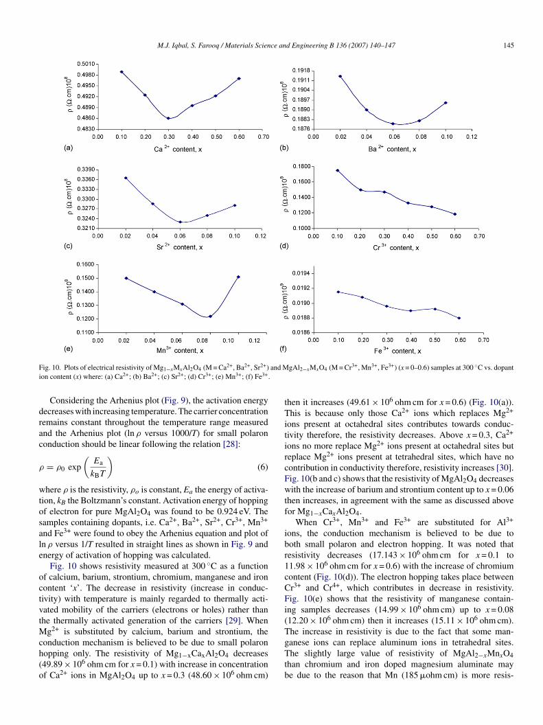
ig. 10. Plots of electrical resistivity of Mg1−xMxAl2O4 (M = Ca2+, Ba2+, Sr2+)on content (x) where: (a) Ca2+; (b) Ba2+; (c) Sr2+; (d) Cr3+; (e) Mn3+; (f) Fe3+.
Considering the Arhenius plot (Fig. 9), the activation energyecreases with increasing temperature. The carrier concentrationemains constant throughout the temperature range measurednd the Arhenius plot (ln ρ versus 1000/T) for small polarononduction should be linear following the relation [28]:
= ρ0 exp
(Ea
kBT
)(6)
here ρ is the resistivity, ρo is constant, Ea the energy of activa-ion, kB the Boltzmann’s constant. Activation energy of hoppingf electron for pure MgAl2O4 was found to be 0.924 eV. Theamples containing dopants, i.e. Ca2+, Ba2+, Sr2+, Cr3+, Mn3+
nd Fe3+ were found to obey the Arhenius equation and plot ofn ρ versus 1/T resulted in straight lines as shown in Fig. 9 andnergy of activation of hopping was calculated.
Fig. 10 shows resistivity measured at 300 ◦C as a functionf calcium, barium, strontium, chromium, manganese and ironontent ‘x’. The decrease in resistivity (increase in conduc-ivity) with temperature is mainly regarded to thermally acti-ated mobility of the carriers (electrons or holes) rather thanhe thermally activated generation of the carriers [29]. When
g2+ is substituted by calcium, barium and strontium, the
onduction mechanism is believed to be due to small polaronopping only. The resistivity of Mg1−xCaxAl2O4 decreases49.89 × 106 ohm cm for x = 0.1) with increase in concentrationf Ca2+ ions in MgAl2O4 up to x = 0.3 (48.60 × 10⁶ ohm cm)gTtb
gAl2−xMxO4 (M = Cr3+, Mn3+, Fe3+) (x = 0–0.6) samples at 300 ◦C vs. dopant
hen it increases (49.61 × 10⁶ ohm cm for x = 0.6) (Fig. 10(a)).his is because only those Ca2+ ions which replaces Mg2+
ons present at octahedral sites contributes towards conduc-ivity therefore, the resistivity decreases. Above x = 0.3, Ca2+
ons no more replace Mg2+ ions present at octahedral sites buteplace Mg2+ ions present at tetrahedral sites, which have noontribution in conductivity therefore, resistivity increases [30].ig. 10(b and c) shows that the resistivity of MgAl2O4 decreasesith the increase of barium and strontium content up to x = 0.06
hen increases, in agreement with the same as discussed aboveor Mg1−xCaxAl2O4.
When Cr3+, Mn3+ and Fe3+ are substituted for Al3+
ons, the conduction mechanism is believed to be due tooth small polaron and electron hopping. It was noted thatesistivity decreases (17.143 × 10⁶ ohm cm for x = 0.1 to1.98 × 106 ohm cm for x = 0.6) with the increase of chromiumontent (Fig. 10(d)). The electron hopping takes place betweenr3+ and Cr4+, which contributes in decrease in resistivity.ig. 10(e) shows that the resistivity of manganese contain-
ng samples decreases (14.99 × 10⁶ ohm cm) up to x = 0.0812.20 × 106 ohm cm) then it increases (15.11 × 10⁶ ohm cm).he increase in resistivity is due to the fact that some man-
anese ions can replace aluminum ions in tetrahedral sites.he slightly large value of resistivity of MgAl2−xMnxO4han chromium and iron doped magnesium aluminate maye due to the reason that Mn (185 �ohm cm) is more resis-

146 M.J. Iqbal, S. Farooq / Materials Science and Engineering B 136 (2007) 140–147
F 2+,Bad f) Fe3
tr1Twrob‘dht0ueua(adchxs
dc
4
ootipt(Bm(a
ig. 11. Plots of activation energy of hopping (Ea)of Mg1−xMxAl2O4 (M = Caopant ion content (x) where: (a) Ca2+; (b) Ba2+; (c) Sr2+; (d) Cr3+; (e) Mn3+; (
ive than Al (2.65 �ohm cm) [31,32]. Fig. 10(f) shows thatesistivity decreases (19.15 × 10⁵ ohm cm for x = 0.1 to8.80 × 105 ohm cm for x = 0.6) with increase of iron content.he transition energy between Fe2+ and Fe3+ is 0.2 eV [33,34],hich indicated pronounced electron hopping and hence
apid decrease in resistivity. Fig. 11 shows the dependencef energy of activation of hopping of electron on calcium,arium, strontium, chromium, manganese and iron contentx’. The variation is similar as the compositional variation ofc electrical resistivity. The samples having high resistivityave high energy of activation and vice versa. The activa-ion energy of hopping for Mg1−xCaxAl2O4 decreases from.881 eV for x = 0.1 to 0.862 eV for x = 0.3 then increasesp to 0.883 eV (Fig. 11(a)). Fig. 11(b) shows that activationnergy of hopping for Mg1−xBaxAl2O4 decreases (0.680 eV)p to x = 0.06 (0.659 eV) then increases. Fig. 11(c) shows thatctivation energy of hopping for Mg1−xSrxAl2O4 decreases0.780 eV) up to x = 0.06 (0.760 eV) then increases. Thectivation energy of hopping of electron for MgAl2−xCrxO4ecreases (0.722–0.631 eV) with an increase in chromium
ontent as shown in Fig. 11(d). The activation energy ofopping for MgAl2−xMnxO4 decreases (0.690 eV) up to= 0.06 (0.665 eV) then increases (Fig. 11(e)). Fig. 11(f)hows that activation energy of hopping for MgAl2−xFexO4R
2+, Sr2+) and MgAl2−xMxO4 (M = Cr3+, Mn3+, Fe3+) (x = 0–0.6) samples vs.+.
ecreases (0.691–0.622 eV) with an increase in ironontent.
. Conclusions
The sol–gel method is found to be suitable for the synthesisf nanosized MgAl2O4 spinel and its derivatives. The resultsf XRD show that lattice constant and X-ray density appearo be affected by the doped metal cations depending upon theironic radii. The dc electrical resistivity studies showed that smallolaron and electron hopping mechanisms takes part in conduc-ivity of the samples investigated here. Decrease in resistivityincrease in conductivity) resulted upon substitution of Ca2+,a2+, Sr2+ at Mg2+ site and Cr3+, Mn3+, Fe3+ at Al3+ site. Ainimum value of activation energy of hopping of electrons
polaron) was noted in case of iron doped magnesium aluminates compared to all other dopants.
eferences
[1] G. Xiong, X. Wei, X. Yang, L. Lu, X. Wang, J. Mater. Sci. 35 (2000)931–936.
[2] D.H. Chen, Y.Y. Chen, J. Collolid Interface Sci. 236 (2001) 41–46.

ce an
[
[
[
[[[
[
[[
[
[
[
[
[[
[
[[
[
[
[[
M.J. Iqbal, S. Farooq / Materials Scien
[3] S. Che, J.F. Wang, Q. Chen, J. Phys. Condense. Matter 15 (2003)L335–L339.
[4] C. Baudin, R. Martinaz, P. Pena, J. Am. Ceram. Soc. 78 (1995) 1857–1862.[5] I. Ganesh, S. Bhattacharjee, B.P. Saha, R. Johnson, R. Rajeshwari, M.V.
Senguptta, R. Ramana, Y.R. Mahajan, Ceram. Int. 28 (2002) 245–253.[6] I. Ganesh, S. Bhattacharjee, B.P. Saha, R. Johnson, Y.R. Mahajan, Ceram.
Int. 21 (2001) 773–779.[7] L.P. Ping, A.M. Azad, T.W. Dung, Mater. Res. Bull. 36 (2001) 1417–1420.[8] J. Salmones, J.A. Galicia, M.A. Wang, G. Valenzuela, A. Rios, J. Mater.
Sci. Lett. 19 (2000) 1033–1037.[9] G. Gusmano, G. Montesperelli, E. Traversa, J. Am. Ceram. Soc. 76 (1993)
743–750.10] J.A. Ball, M. Pirzada, R.W. Grims, M.O. Zaceta, D.W. Price, B.P. Uberuaga,
J. Phys. Condense. Matter 17 (2005) 7621–7631.11] L. Guang, L. Ikegami, L. Jong-Heun, T. Mori, J. Am. Ceram. Soc. 83 (2000)
2866–2868.12] S. Kurien, S. Sebastian, J. Mathew, K.C. George, Indian J. Pure Appl. Phys.
42 (2004) 926–933.13] D. Jia, W.M. Yen, J. Lumin. 101 (2003) 115–121.14] C. Garapon, H. Manaa, R. Moncoge, J. Chem. Phys. 95 (1991) 5501–5512.15] A. Tomita, T. Sato, K. Tanaka, Y. Kawabe, M. Shirai, E. Hanamura, J.
Lumin. 109 (2004) 19–24.
16] T. Sato, M. Shirai, K. Tanaka, Y. Kawabe, E. Hanamura, J. Lumin. 114(2005) 155–161.17] H. Zhang, X. Jia, Z. Liu, Z. Li, Mater. Lett. 58 (2004) 1625–1628.18] H.P. Klug, L.E. Alexender, X-ray Diffraction Procedures for Polycrystalline
and Amorphous Materials, 2nd ed., Wiley–Interscience, New York, 1974.
[
[[
d Engineering B 136 (2007) 140–147 147
19] T. Abbas, M.U. Islam, M. Ashraf, Mod. Phys. Lett. B 9 (1995) 1419–1426.
20] J. Guo, H. Lou, H. Zhao, X. Wang, X. Zhang, Mater. Lett. 58 (2004)1920–1923.
21] I.S.A. Farag, M.A. Ahmad, S.M. Hammad, A.M. Moustafa, Egypt. J. Sol.24 (2001) 215–225.
22] Y.S. Hong, C.M. Ho, H.Y. Hsu, C.T. Liu, J. Magn. Magn. Mater. 279 (2004)401–410.
23] A.A. Sattar, Egypt. J. Sol. 27 (2004) 99–110.24] M.M. Barakat, M.A. Henaish, S.A. Olofa, A. Tawfik, J. Therm. Anal.
Calorim. 37 (1991) 241–248.25] H.V. Keer, M.G. Bodas, A. Bhaduri, A.B. Biswas, J. Inorg. Nucl. Chem.
37 (1975) 1605–1607.26] J. Nell, B. Wood, J. Am. Miner. 76 (1991) 405–426.27] S. Angappan, L.J. Berchmans, C.O. Augustin, Mater. Lett. 58 (2004)
2283–2289.28] R. Raman, V.R.K. Murthy, B. Viswanathan, J. Appl. Phys. 69 (1991)
4053–4055.29] N. Iftimie, E. Rezlescu, P.D. Popa, N. Rezlescu, J. Optoelectron. Adv.
Mater. 7 (2005) 911–914.30] J. Nell, B.J. Wood, O.T. Mason, Am. Miner. 74 (1989) 339–351.31] U. Ghazanfar, S.A. Siddiqi, G. Abbas, Mater. Sci. Eng. B 118 (2005)
132–134.32] C. Kittle, An Introduction to Solid State Physics, 5th ed., Wiley, London,
1976.33] A.J. Bosmsn, H.J. Van, Adv. Phys. 19 (1970) 1–5.34] A.A. Sattar, Egypt. J. Sol. 26 (2003) 113–121.