Properties of Activated Carbon Bl acks Filled SBR Rubber ...
EFFECT OF DIFFERENT ORIGIN OF NATURAL RUBBER, CARBON
BLACK LOADING, AND VULCANIZATION SYSTEMS ON PROPERTIES
OF NATURAL RUBBER COMPOUNDS
YOS PHANNY
UNIVERSITI SAINS MALAYSIA
2011
EFFECT OF DIFFERENT ORIGIN OF NATURAL RUBBER, CARBON
BLACK LOADING, AND VULCANIZATION SYSTEMS ON PROPERTIES
OF NATURAL RUBBER COMPOUNDS
by
YOS PHANNY
Thesis submitted in fulfillment of the
requirements for the degree of
Master of Science
June 2011
ii
ACKNOWLEDGEMENTS
Firstly, I would like to thank to my scholarship sponsor AUN/SEED.Net for their
financial support for this M.Sc program. Thank you to Universiti Sains Malaysia (USM) and
School of Materials and Mineral Resources Engineering (SMMRE) for their cooperation.
I would like to express my sincere appreciation to my supervisors Assoc. Prof. Dr.
Azura A. Rashid and Prof. Hanafi Ismail (USM) for their supervisions, advices,
encouragement and warm hospitality. Also, I would like to express my sincere
acknowledgement to Assistant Prof. Dr. Tosaka Masatoshi, Division of Materials Chemistry-
Polymer Controlled Synthesis, Institute for Chemical Research, Kyoto University, for his
valuable comments. I would like to thank my advisor Mr. Phat Boné, Institute of Technology
of Cambodia for his support.
Unforgettably, I would like to convey my special thanks to the Dean, Deputy Dean,
lecturers and all staffs of SMMRE for their kind assistants and supports.
Finally, I would like to express my highest gratitude to my parents, relatives and
friends for their care and supports.
iii
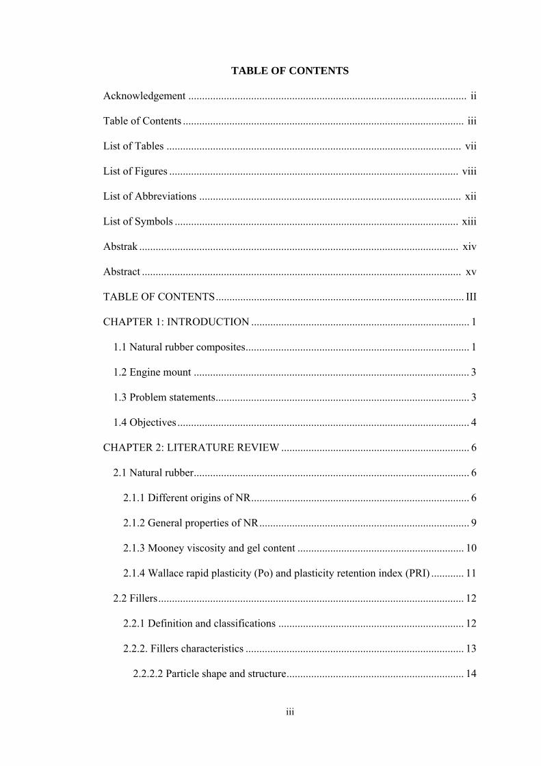
TABLE OF CONTENTS
Acknowledgement ...................................................................................................... ii
Table of Contents ....................................................................................................... iii
List of Tables ............................................................................................................ vii
List of Figures .......................................................................................................... viii
List of Abbreviations ................................................................................................ xii
List of Symbols ........................................................................................................ xiii
Abstrak ..................................................................................................................... xiv
Abstract ..................................................................................................................... xv
TABLE OF CONTENTS ........................................................................................... III
CHAPTER 1: INTRODUCTION ................................................................................ 1
1.1 Natural rubber composites .................................................................................. 1
1.2 Engine mount ..................................................................................................... 3
1.3 Problem statements ............................................................................................. 3
1.4 Objectives ........................................................................................................... 4
CHAPTER 2: LITERATURE REVIEW ..................................................................... 6
2.1 Natural rubber ..................................................................................................... 6
2.1.1 Different origins of NR ................................................................................ 6
2.1.2 General properties of NR ............................................................................. 9
2.1.3 Mooney viscosity and gel content ............................................................. 10
2.1.4 Wallace rapid plasticity (Po) and plasticity retention index (PRI) ............ 11
2.2 Fillers ................................................................................................................ 12
2.2.1 Definition and classifications .................................................................... 12
2.2.2. Fillers characteristics ................................................................................ 13
2.2.2.2 Particle shape and structure ................................................................. 14
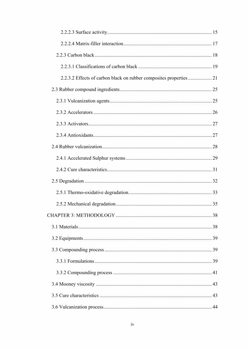
iv
2.2.2.3 Surface activity .................................................................................... 15
2.2.2.4 Matrix-filler interaction ....................................................................... 17
2.2.3 Carbon black .............................................................................................. 18
2.2.3.1 Classifications of carbon black ........................................................... 19
2.2.3.2 Effects of carbon black on rubber composites properties ................... 21
2.3 Rubber compound ingredients .......................................................................... 25
2.3.1 Vulcanization agents .................................................................................. 25
2.3.2 Accelerators ............................................................................................... 26
2.3.3 Activators ................................................................................................... 27
2.3.4 Antioxidants ............................................................................................... 27
2.4 Rubber vulcanization ........................................................................................ 28
2.4.1 Accelerated Sulphur systems ..................................................................... 29
2.4.2 Cure characteristics .................................................................................... 31
2.5 Degradation ...................................................................................................... 32
2.5.1 Thermo-oxidative degradation ................................................................... 33
2.5.2 Mechanical degradation ............................................................................. 35
CHAPTER 3: METHODOLOGY ............................................................................. 38
3.1 Materials ........................................................................................................... 38
3.2 Equipments ....................................................................................................... 39
3.3 Compounding process ...................................................................................... 39
3.3.1 Formulations .............................................................................................. 39
3.3.2 Compounding process ............................................................................... 41
3.4 Mooney viscosity ............................................................................................. 43
3.5 Cure characteristics .......................................................................................... 43
3.6 Vulcanization process ....................................................................................... 44
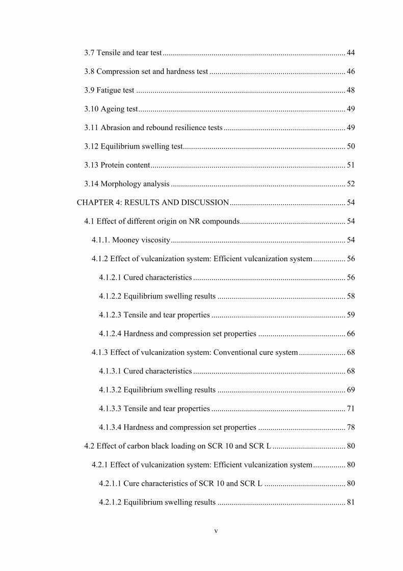
v
3.7 Tensile and tear test .......................................................................................... 44
3.8 Compression set and hardness test ................................................................... 46
3.9 Fatigue test ....................................................................................................... 48
3.10 Ageing test ...................................................................................................... 49
3.11 Abrasion and rebound resilience tests ............................................................ 49
3.12 Equilibrium swelling test ................................................................................ 50
3.13 Protein content ................................................................................................ 51
3.14 Morphology analysis ...................................................................................... 52
CHAPTER 4: RESULTS AND DISCUSSION ......................................................... 54
4.1 Effect of different origin on NR compounds .................................................... 54
4.1.1. Mooney viscosity ...................................................................................... 54
4.1.2 Effect of vulcanization system: Efficient vulcanization system ................ 56
4.1.2.1 Cured characteristics ........................................................................... 56
4.1.2.2 Equilibrium swelling results ............................................................... 58
4.1.2.3 Tensile and tear properties .................................................................. 59
4.1.2.4 Hardness and compression set properties ........................................... 66
4.1.3 Effect of vulcanization system: Conventional cure system ....................... 68
4.1.3.1 Cured characteristics ........................................................................... 68
4.1.3.2 Equilibrium swelling results ............................................................... 69
4.1.3.3 Tensile and tear properties .................................................................. 71
4.1.3.4 Hardness and compression set properties ........................................... 78
4.2 Effect of carbon black loading on SCR 10 and SCR L .................................... 80
4.2.1 Effect of vulcanization system: Efficient vulcanization system ................ 80
4.2.1.1 Cure characteristics of SCR 10 and SCR L ........................................ 80
4.2.1.2 Equilibrium swelling results ............................................................... 81

vi
4.2.1.3 Tensile and tear properties .................................................................. 83
4.2.1.4 Fatigue life .......................................................................................... 88
4.2.1.5 Hardness and compression set ............................................................ 89
4.2.1.6 Rebound resilience and abrasion ......................................................... 92
4.2.1.6 Effect of ageing on tensile properties of SCR 10 ................................ 93
4.2.2 Comparison between Efficient vulcanization system and Conventional
vulcanization system for SCR 10 ....................................................................... 96
4.2.2.1 Cure characteristics ............................................................................. 96
4.2.2.2 Equilibrium swelling results ............................................................... 97
4.2.2.2 Tensile properties ................................................................................ 98
4.2.2.3 Fatigue life ........................................................................................ 100
4.2.2.4 Effect of ageing on tensile properties ................................................ 101
CHAPTER 5: CONCLUSIONS AND SUGGESTIONS FOR FUTURE WORK .. 104
5.1 Conclusions .................................................................................................... 104
5.2 Suggestions for future work ........................................................................... 106
vii
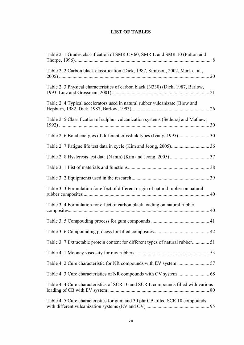
LIST OF TABLES Table 2. 1 Grades classification of SMR CV60, SMR L and SMR 10 (Fulton and Thorpe, 1996) ............................................................................................................... 8
Table 2. 2 Carbon black classification (Dick, 1987, Simpson, 2002, Mark et al., 2005) .......................................................................................................................... 20
Table 2. 3 Physical characteristics of carbon black (N330) (Dick, 1987, Barlow, 1993, Lutz and Grossman, 2001) ............................................................................... 21
Table 2. 4 Typical accelerators used in natural rubber vulcanizate (Blow and Hepburn, 1982, Dick, 1987, Barlow, 1993) ............................................................... 26
Table 2. 5 Classification of sulphur vulcanization systems (Sethuraj and Mathew, 1992) .......................................................................................................................... 30
Table 2. 6 Bond energies of different crosslink types (Ivany, 1995) ......................... 30
Table 2. 7 Fatigue life test data in cycle (Kim and Jeong, 2005) ............................... 36
Table 2. 8 Hysteresis test data (N mm) (Kim and Jeong, 2005) ................................ 37
Table 3. 1 List of materials and functions .................................................................. 38
Table 3. 2 Equipments used in the research ............................................................... 39
Table 3. 3 Formulation for effect of different origin of natural rubber on natural rubber composites ...................................................................................................... 40
Table 3. 4 Formulation for effect of carbon black loading on natural rubber composites .................................................................................................................. 40
Table 3. 5 Compouding process for gum compounds ............................................... 41
Table 3. 6 Compounding process for filled composites ............................................. 42
Table 3. 7 Extractable protein content for different types of natural rubber .............. 51
Table 4. 1 Mooney viscosity for raw rubbers ............................................................ 53
Table 4. 2 Cure characteristic for NR compounds with EV system .......................... 57
Table 4. 3 Cure characteristics of NR compounds with CV system .......................... 68
Table 4. 4 Cure characteristics of SCR 10 and SCR L compounds filled with various loading of CB with EV system .................................................................................. 80
Table 4. 5 Cure characteristics for gum and 30 phr CB-filled SCR 10 compounds with different vulcanization systems (EV and CV) ................................................... 95
viii
List of Figures
Figure 2. 1 (a) Hevea braziliensis, (b) Castilloa elastica, (c) Ficus elastica, and (d) Landolphia owariensis (Loadman, 2005) ..................................................................... 7
Figure 2. 2 Repeat unit of NR (polyisoprene) (Simpson, 2002) ................................ 10
Figure 2. 3 The fillers various morphology with aspect ratio (Sekutowski, 1996) .... 15
Figure 2. 4 SEM micrographs of fracture surfaces of various NR vulcanizates: (a) Control, (b) N330, (c) N550 and (d) N774 (Rattanasom and Prasertsri, 2009) ......... 16
Figure 2. 5 Surface chemistry of carbon black (Leblanc, 2002) ................................ 19
Figure 2. 6 TEM micrograph of carbon black N326: (a) low structure and (b) high structure (Wypych, 2000) .......................................................................................... 19
Figure 2. 7 Effect of curing temperature on the mechanical properties of NR vulcanizates: □, ∆ and ○ represent gum CV, SEV and EV; ■, ▲ and ● represent N330-filled CV, SEV and EV vulcanizates (Fan et al., 2001) ................................... 22
Figure 2. 8 The behavior of swelling ratio for NBR vulcanizates at different temperature as a function of carbon black loading (Mostafa et al., 2009) ................. 23
Figure 2. 9 The effect of carbon black loading on the compression set of SBR and NBR filled compounds (Mostafa et al., 2009) ........................................................... 24
Figure 2. 10 Dynamic compression set of NR vulcanizates with various fillers at various content, where C–Clay, CB–Carbon black and S–Silica (Rattanasom et al., 2009) .......................................................................................................................... 24
Figure 2. 11 General structure of PPDs (Dick, 2003) ................................................ 28
Figure 2. 12 In vulcanization the randomly oriented chains of raw rubber become cross-linked as indicated diagrammatically at the right (Rodgers, 2004) .................. 28
Figure 2. 13 Structural features of vulcanisate network (Blow and Hepburn, 1982) 29
Figure 2. 14 Cure profile of CV, semi-EV and EV vulcanizates (Henning, 2007) ... 31
Figure 2. 15 General degradation activities of natural rubber compounds (IRI, 1998) .................................................................................................................................... 33
Figure 2. 16 Thermal decomposition (IRI, 1998) ...................................................... 34
Figure 2. 17 Mechanism of oxidative degradation of olefins (Bolland and Have, 1947) .......................................................................................................................... 35
Figure 3. 1 Shape and dimension of tensile test specimens ....................................... 45
Figure 3. 2 Shape and dimension of tear test specimen in trouser type ..................... 46
ix
Figure 3. 3 Device for compression set under constant deflection ............................ 47
Figure 3. 4 Changes of sample thickness as function of time for compression set testing (Brown, 1986) ................................................................................................ 48
Figure 3. 5 Fatigue specimen shape and dimension (ASTM D 4482) ....................... 48
Figure 3. 6 Overall flow chart of the research work .................................................. 52
Figure 4. 1 Effect of mastication time on Mooney viscosity ..................................... 54
Figure 4. 2 (a) Swelling ratio and (b) crosslink density for different origins of gum NR and 30 phr CB-filled NR compounds with EV system ....................................... 58
Figure 4. 3 Tensile strength for different origins of gum NR and 30 phr CB-filled NR compounds with EV system ....................................................................................... 60
Figure 4. 4 Elongation at break for different origins of gum NR and 30 phr CB-filled NR compounds with EV system ................................................................................ 61
Figure 4. 5 Tensile modulus at (a) 100% and (b) 300% elongation for different origins of gum NR and 30 phr CB-filled NR compounds with EV system ............... 61
Figure 4. 6 Tear strength for different origins of gum NR and 30 phr CB-filled NR compounds with EV system ....................................................................................... 62
Figure 4. 7 SEM micrograph for tensile fracture surface of gum NR compounds (a) SMR CV60, (b) SVR 3L (c) SCR 10 and (d) SCR L (mag. 30x) .............................. 64
Figure 4. 8 SEM micrograph for tensile fracture surface of 30 phr CB-filled NR compounds (a) SMR CV60, (b) SVR 3L, (c) SCR 10 and (d) SCR L (mag. 30x) .... 65
Figure 4. 9 Hardness for different origins of gum NR and 30 phr CB-filled NR compounds ................................................................................................................. 66
Figure 4. 10 Compression set for different origins of gum NR and 30 phr CB-filled NR compounds ........................................................................................................... 67
Figure 4. 11 (a) Swelling ratio and (b) crosslink density of different origins for gum NR and 30 phr CB-filled NR compounds with CV system ....................................... 70
Figure 4. 12 Tensile strength of different origins for gum NR and 30 phr CB-filled NR compounds with CV system ................................................................................ 72
Figure 4. 13 Elongation at break of different origins for gum NR and 30 phr CB-filled NR compounds with CV system ...................................................................... 73
Figure 4. 14 Tensile modulus at (a) 100% and (b) 300% elongation of different origins for gum NR and 30 phr CB-filled NR compounds with CV system ............. 73
Figure 4. 15 SEM micrographs of tensile fracture surface for gum NR compounds (a) SMR CV60 (b) SVR 3L, (c) SCR 10 and (d) SCR L (mag. 30x) .............................. 75

x
Figure 4. 16 SEM micrograph of tensile fracture surface for 30 phr CB-filled NR compounds (a) SMR CV60, (b) SVR 3L (c) SCR 10 and (d) SCR L, Arrows show the agglomerations ..................................................................................................... 76
Figure 4. 17 Tear strength of different origins for gum NR and 30 phr CB-filled NR compounds with CV system ...................................................................................... 77
Figure 4. 18 Hardness of different origins for gum NR and 30 phr CB-filled NR compounds ................................................................................................................. 78
Figure 4. 19 Compression set of different origins for gum NR and 30 phr CB-filled NR compounds ........................................................................................................... 79
Figure 4. 20 (a) Swelling ratio and (b) crosslink density for SCR 10 and SCR L compounds filled with various loading of CB with EV system ................................. 82
Figure 4. 21 The dispersion of CB filled SCR 10 at 40 phr with EV system ............ 82
Figure 4. 22 Tensile strength for SCR 10 and SCR L compounds filled with various loading of CB with EV system .................................................................................. 84
Figure 4. 23 Elongation at break for SCR 10 and SCR L compounds filled with various loading of CB with EV system ...................................................................... 84
Figure 4. 24 Tensile modulus at (a) 100% and (b) 300% elongation for SCR 10 and SCR L compounds filled with various loading of CB with EV system ..................... 85
Figure 4. 25 SEM micrographs for CB dispersion in SCR 10 compounds (a) CB 20 phr, (b) CB 30phr and (c) CB 40 phr ........................................................................ 86
Figure 4. 26 Tear strength for SCR 10 and SCR L compounds filled with various loading of CB with EV system .................................................................................. 87
Figure 4. 27 Fatigue life for SCR 10 and SCR L compounds filled with various loading of CB with EV system .................................................................................. 88
Figure 4. 28 SEM fatigue fracture surface at 30 phr CB-filled SCR 10 .................... 89
Figure 4. 29 Hardness for SCR 10 and SCR L compounds filled with various loading of CB with EV system ............................................................................................... 90
Figure 4. 30 Compression set for SCR 10 and SCR L compounds filled with various loading of CB with EV system .................................................................................. 91
Figure 4. 31 Rebound resilience for SCR 10 and SCR L compounds filled with different loading of CB with EV system .................................................................... 92
Figure 4. 32 Abrasion rate of SCR 10 and SCR L compounds filled with various loading of CB with EV system .................................................................................. 93
Figure 4. 33 Tensile strength for SCR 10 compounds filled with various loading of CB with EV system after ageing for 1 day and 3 days at 100 oC .............................. 94

xi
Figure 4. 34 Elongation at break for SCR 10 compounds filled with various loading of CB with EV system after ageing for 1 day and 3 days at 100 oC .......................... 95
Figure 4. 35 Tensile modulus at (a) 100% and (b) 300% elongation for SCR 10 compounds filled with various loading of CB with EV system after ageing for 1 day and 3 days at 100 oC ................................................................................................... 95
Figure 4. 36 (a) Swelling ratio and (b) crosslink density for gum and 30 phr CB-filled SCR 10 compounds with EV and CV systems .......................................................... 98
Figure 4. 37 Tensile properties: (a) Tensile strength, (b) Elongation at break, (c) M100 and (d) M300 for SCR 10 compounds with EV and CV systems ................... 99
Figure 4. 38 SEM micrograph for tensile surface fractures of compounds filled with 30 phr CB (a) with CV system and (b) with EV system. Arrows show hole and agglomeration ........................................................................................................... 100
Figure 4. 39 Fatigue life of gum and 30 phr CB-filled SCR 10 compounds with EV and CV systems ........................................................................................................ 101
Figure 4. 40 Tensile strenght for gum and 30 phr CB-filled SCR 10 compounds after ageing for 1 and 3 days at 100 oC with EV and CV systems ................................... 102
Figure 4. 41 Elongation at break for gum and 30 phr CB-filled SCR 10 compounds after ageing for 1 and 3 days at 100 oC with EV and CV systems ........................... 103
Figure 4. 42 Tensile modulus M100 for gum and 30 phr CB-filled SCR 10 compounds after ageing for 1 and 3 days at 100 oC with EV and CV systems ....... 103
xii
List of Abbreviations ASTM American Standard for Testing and Materials
CB Carbon black
CBS N-cyclohexyl-2-benzothiazole sulfonamide
CRI Cure Rate Index
CV Conventional vulcanization
EV Efficient vulcanization
IPPD N-isopropyl-N’-phenyl-p-phenylenediamine
IRHD International Rubber Hardness Degree
JIS Japan Industrial Standard
NR Natural rubber
phr Part per hundred rubber
PRI Plasticity retention index
SCR Specified Cambodian Rubber
SEM Scanning Electron Microscopy
SMR Standard Malaysian Rubber
SVR Standard Vietnamese Rubber
TSR Technically Specified Rubber
xiii
List of Symbols C Compression set
d Thickness
F Force
M100 Tensile modulus at 100% elongation
M300 Tensile modulus at 300% elongation
Mc Number average molecular weight of network chains
MH Maximum torque
ML Minimum torque
Mo Original weight
Mt Swelling weight
Po Wallace plasticity
Q Swelling ratio
t90 Cure time
tf Final thickness
ti Original thickness
Ts Tear strength
ts Thickness of the spacer bar
ts2 Scorch time
Vl Molar volume of the swelling liquid
Vr The volume fraction of rubber in the swollen material
A solvent-rubber interaction constant
Density of the network
xiv
KESAN PERBEZAAN TEMPAT ASAL, PEMBEBANAN HITAM KARBON
(CB) DAN SISTEM PEMVULKANAN KE ATAS SIFAT SIFAT SEBATIAN
GETAH ASLI
ABSTRAK
Dalam kajian ini, kelikatan Mooney bagi getah asli yang diperolehi daripada
Malaysia (SMR CV60), Kemboja (SCR 10 dan SCR L) dan Vietnam (SVR 3L) telah
diuji. Kesan tempat asal, pembebanan hitam karbon (CB) dan sistem pemvulkanan
yang berbeza (sistem pemvulkanan cekap (EV) dan pemvulkanan lazim (CV)) telah
dikaji. Getah asli yang diperolehi daripada tempat yang berbeza menunjukkan sifat-
sifat vulkanizat yang berbeza disebabkan oleh berat molekul dan kandungan protein.
Di dalam sistem EV, oleh sebab berat molekul dan kandungan protein yang tinggi
yang terdapat di dalam SCR 10, kadar pemvulkanan bagi sebatian tanpa pengisi dan
sebatian berpengisi adalah cepat. Bagi sistem CV pula, SCR L yang mempunyai
berat molekul yang rendah tetapi mempunyai kandungan protein yang tinggi
menunjukkan kadar pemvulkanan yang cepat. Kesan pembebanan CB dapat dilihat
secara menyeluruh dengan peningkatan pembebanan CB dapat meningkatkan sifat-
sifat fizikal and mekanikal sebatian getah asli tetapi pada masa yang sama, ia
mengurangkan ketahanan terhadap kelesuan yang disebabkan oleh kestabilan
sebatian. Sebatian yang menggunakan sistem CV menunjukkan sifat-sifat fizikal dan
mekanikal yang lebih tinggi berbanding sistem EV, tetapi daya tahan terhadap haba
yang lemah disebabkan oleh pemutusan sambung silang polisulfida.
xv
EFFECT OF DIFFERENT ORIGIN OF NATURAL RUBBER, CARBON
BLACK LOADING, AND VULCANIZATION SYSTEMS ON PROPERTIES
OF NATURAL RUBBER COMPOUNDS
ABSTRACT
In this research, Mooney viscosity was tested for natural rubber (NR) from
Malaysia (SMR CV60), Cambodia (SCR 10 and SCR L) and Vietnam (SVR 3L).
The effect of different origins of NR, different loading of carbon black (CB) filled
NR compounds, and different vulcanization systems (efficient vulcanization (EV)
and conventional vulcanization (CV) systems) were studied. Origins of NR showed
different cure characteristics due to molecular weight and protein content. In EV
system, SCR10 possesses higher molecular weight and protein content hence give
faster cure rate for both gum and filled compounds. For CV system SCR L possesses
lower molecular chain but higher protein content exhibiting faster cure rate for gum
compound. For effect of CB loading, higher CB loading significantly increased the
physical and mechanical properties of NR compounds, but decreases fatigue life due
to stability of the compound. Compounds with CV system show higher physical and
mechanical properties compared to EV system, but CV system are vulnerable to heat
ageing due to the breakage of polysulphidic crosslinks.
1
CHAPTER 1
INTRODUCTION
The rubber industry is a full-grown industry which really became known as a
commercial enterprise after Charles Goodyear found out how to vulcanize rubber in
1839. From its early applications in shoe soles and bicycle tires, the industry has
started a wide variety of products such as truck tires, farm tires, passenger tires, off-
the-road tires, hose, conveyor belts, molded mechanical goods, matting and sheeting,
tank lining, V-belts, shoe heel and soles, and sponge rubber.
1.1 Natural rubber composites
Rubbers are extensively used in many applications for their large reversible
elastic deformation, excellent damping and energy absorption characteristic.
Difference from other polymers, natural rubber (NR) is highly vulnerable to
degradation, due to the presence of double bonds in the main chain. NR is easy to be
attacked by solvents, deteriorated by oxygen, ozone, sun light, UV rays as well as
humidity (Vinod et al., 2002). Therefore, reinforcing fillers are necessarily added
into NR in most cases in order to gain appropriate properties for specific applications
(Blow and Hepburn, 1982, Ismail and Poh, 2000, Choi et al., 2003). Rubber mount is
widely used in vehicles powertrain (group of components that generate power and
deliver it to the road surface, water or air) mounting system and plays an important
role in noise, vibration and harshness (NVH) reduction. Also, it is used in vehicle cab
mounting system, wheel suspension system, and other mobile or stationary
machines’ mounting systems (Blow and Hepburn, 1982, Mark, 2007).
2
A composite material is a material brought about by combining materials
differing in composition or form on a macroscale for the purpose of obtaining
specific characteristics and properties. The constituents retain their identity such that
they can be physically identified and they exhibit an interface between one another
(Schwartz, 1992). Rubber composites are rubber vulcanizates with fillers. The
properties of composites depend on interaction of fillers with elastomer including
extensity, intensity and geometrical factors (Blow and Hepburn, 1982, Osman and
Atallah, 2006, Fu et al., 2008). Fillers also have been used in rubber to cheapen the
products and do not strongly affect the vulcanizate properties in rubber. The use of
fillers in rubber is almost as old as the use of rubber itself (Blow and Hepburn,
1982). For a filler to provide significant reinforcement, it must possess high specific
surface area. Small particles have large surface area to interact with the rubber and
close particle-to-particle spacing in the compound. Carbon black and silica are two
types of fillers that are most effective for reinforcing rubber. They can be produced
with a primary particle size as small as 100 Ǻ, corresponding to a surface area of a
few hundred m2 per gram of filler (Gent, 2001).
Origins of NR have been reported for their different in properties such
molecular weight, gel content, protein content and nitrogen effect. Nitrogen groups
from Hevea brasiliensis have been regarded as an important factor governing cured
rubber properties (Sakdapipanich, 2007). Moreover, protein in NR have long been
considered to be essential component that affect to the characteristic properties of
NR, mainly cured rubber properties. Chenal et al. (2007) showed that decrease in
average molecular weight leads to decrease in the crystallite growth at high crosslink
density while crystallite volume is quasi-independent on average molecular weight at
3
weak crosslink density. Bhowmick et al. (1986) showed that Hevea braziliensis is
superior to synthetic Natsyn and guayule rubber in terms of mechanical and
rheological properties for the same isoprene backbone chain.
1.2 Engine mount
The engine mounts are used to isolate engine vibration and prevent engine
bounce from shock excitation. Engine mount improvement has been made for the
requirement of vibration and noise level and for modern car designs having a trend
for lighter car body with more power-intensive engines. Different types of engine
mounting systems, from elastomeric to hydraulic and from passive to active, have
been developed to improve the mount performance. Elastomeric mounts are rubber
mounts designed for the necessary elastic stiffness rate characteristics in all
directions for proper vibration isolation. Passive hydraulic mounts can provide a
better performance than elastomeric mounts especially at low frequency. Semi-active
techniques are usually used to further improve performance of hydraulic mounts by
making them more tunable which meant one or more system parameters can be
controlled to adjust the dynamic response of the system. The active engine mounting
system can be very stiff at low frequency and be tuned to be very soft at the higher
frequency range to isolate vibration (Kim and Singh, 1995, Yu et al., 2001, Hillis et
al., 2005).
1.3 Problem statements
Cambodia still has limited knowledge of natural rubber composites and all
natural rubber in form of dry rubber is exported to nearby countries. As more rubber
trees are now planting in many parts of country, Cambodian natural rubber was used
4
to study the properties in composites which are expected to be very useful in future
work in Cambodia.
Different origins of rubber give different properties, hence very important to
studies each property. Vulcanization systems also play important roles in
determining rubber vulcanizates properties. Accelerated sulphur system is the most
popular system for rubber compounding. Efficient vulcanization and conventional
vulcanization systems are used to study the different properties of rubber composites
for this research.
Addition of carbon black (CB) to certain loading has been found to offer
substantial improvement in the mechanical properties of rubber because of its
compatibility with rubber, but it will decreased to higher loading of CB. It was
chosen in this study due to its significant reinforcement in rubber composites. Anti-
vibration, damping, and noise; mounts are usually affected by fatigue action,
compression, and loss of resilience. Mostly, engine mounts, being used as seal or
lining, are faced with motor oil or other hydrocarbon such as petrol which caused
swelling.
1.4 Objectives
This study was conducted to give better understanding on properties of
natural rubber composites affected by different origin of natural rubber (Malaysian,
Vietnamese and Cambodian natural rubber) with conventional vulcanization (CV)
and efficient vulcanization (EV) systems. It also aimed to investigate the effect of
carbon black loading on Cambodian natural rubber with EV system and the effect of
5
different vulcanization systems, CV versus EV systems, on SCR 10 rubber. This
work was carried out to achieve the following objectives:
i. To determine the properties of natural rubber composites with different
origins of natural rubber
ii. To determine the effect of carbon black loading on physical and
mechanical properties of the properties of Cambodian natural rubber composites.
iii. To investigate the effect of different cure systems, CV and EV systems,
on SCR 10 rubber composites at 30 phr carbon black loading.
6
CHAPTER 2
LITERATURE REVIEW
2.1 Natural rubber
2.1.1 Different origins of NR
Natural rubber (NR) can be extracted from different plant species which only
a few are commercially important. There are a number of tree species for rubber
which are native to many parts of Africa and the Far East. The outstanding source of
natural rubber is the large forest tree Hevea brasiliensis, located in the southern
equatorial region of America. It was brought to India in 1876 and sent to equatorial
part such as Java, Borneo and Ceylon and more particularly in Malaya for the
cultivation of rubber trees (Blow and Hepburn, 1982, Sethuraj and Mathew, 1992,
Loadman, 2005). The Hevea Brasiliensis trees can grow up to 30 m high with a
main trunk of about 50 cm diameter (Kothandaraman, 2008). Some historical interest
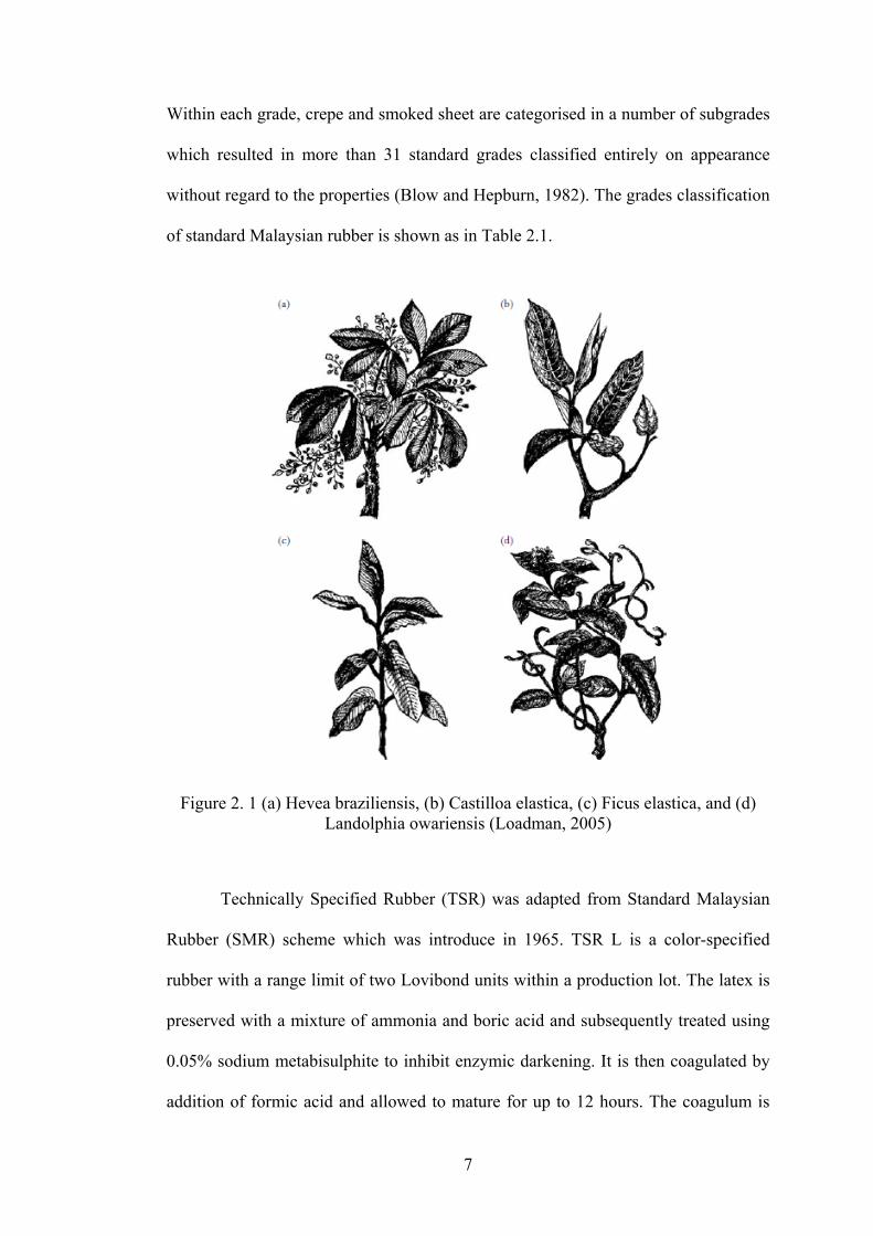
rubber trees are listed below and Hevea braziliensis (Figure 2.1 (a)) produces almost
all of the natural rubber products in the world (Loadman, 2005).
- Castilloa (elastica and ulei): The former is found in Central America and
Mexico (Figure 2.1(b)), the latter in Peru and Brazil.
- Manihot glaziovii: From the Ceara region of Brazil.
- Ficus elastica: Found in Java and Malaysia (Figure 2.1 (c))
- Landolphia: Creepers found mainly in the Congo basin (Figure 2.1 (d))
- Funtumia elastica: Found in West Africa.
For many years there have been two mains types of rubber; crepe prepared by
coagulating the latex, washing, rolling, and drying the coagulum; and smoked sheet
prepared similar as creep rubber but drying the coagulum in the presence of smoke.
7
Within each grade, crepe and smoked sheet are categorised in a number of subgrades
which resulted in more than 31 standard grades classified entirely on appearance
without regard to the properties (Blow and Hepburn, 1982). The grades classification
of standard Malaysian rubber is shown as in Table 2.1.
Figure 2. 1 (a) Hevea braziliensis, (b) Castilloa elastica, (c) Ficus elastica, and (d) Landolphia owariensis (Loadman, 2005)
Technically Specified Rubber (TSR) was adapted from Standard Malaysian
Rubber (SMR) scheme which was introduce in 1965. TSR L is a color-specified
rubber with a range limit of two Lovibond units within a production lot. The latex is
preserved with a mixture of ammonia and boric acid and subsequently treated using
0.05% sodium metabisulphite to inhibit enzymic darkening. It is then coagulated by
addition of formic acid and allowed to mature for up to 12 hours. The coagulum is
8
processed into crumb form, followed by hot air drying at 100 oC and the dried
crumbs are cooled to 60 oC and compressed into standard bales. For TSR CV, natural
rubber undergoes an irreversible increase in viscosity that occurs during transport
and storage.
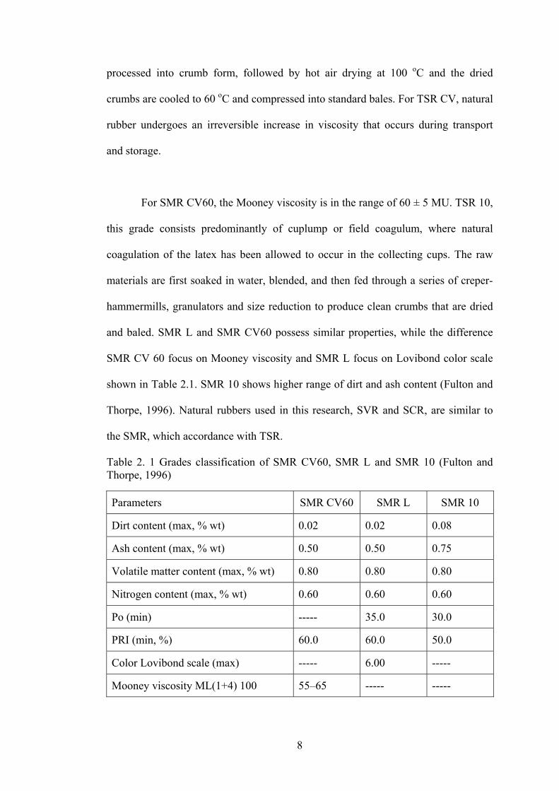
For SMR CV60, the Mooney viscosity is in the range of 60 ± 5 MU. TSR 10,
this grade consists predominantly of cuplump or field coagulum, where natural
coagulation of the latex has been allowed to occur in the collecting cups. The raw
materials are first soaked in water, blended, and then fed through a series of creper-
hammermills, granulators and size reduction to produce clean crumbs that are dried
and baled. SMR L and SMR CV60 possess similar properties, while the difference
SMR CV 60 focus on Mooney viscosity and SMR L focus on Lovibond color scale
shown in Table 2.1. SMR 10 shows higher range of dirt and ash content (Fulton and
Thorpe, 1996). Natural rubbers used in this research, SVR and SCR, are similar to
the SMR, which accordance with TSR.
Table 2. 1 Grades classification of SMR CV60, SMR L and SMR 10 (Fulton and Thorpe, 1996)
Parameters SMR CV60 SMR L SMR 10
Dirt content (max, % wt) 0.02 0.02 0.08
Ash content (max, % wt) 0.50 0.50 0.75
Volatile matter content (max, % wt) 0.80 0.80 0.80
Nitrogen content (max, % wt) 0.60 0.60 0.60
Po (min) ----- 35.0 30.0
PRI (min, %) 60.0 60.0 50.0
Color Lovibond scale (max) ----- 6.00 -----
Mooney viscosity ML(1+4) 100 55–65 ----- -----
9
Cornish (2001) made a review on the investigation of rubber biochemistry
factors that affecting rubber yield (biosynthetic rate, substrate availability and rubber
particle size, number and ontogeny(growing)) and rubber quality (primarily rubber
molecular weight) among plant species. She compared three different types of
rubber, Hevea brasiliensis, Parthenium argentatum and Ficus elastica. The amount of
protein associated with rubber particles varies tremendously between species and the
number of different proteins is remarkably different. Hevea brasiliensis contains the
most complicated particles. It is found that Hevea brasiliensis and Parthenium
argentatum contain high molecular weight rubber while Ficus elastica contains low
molecular weight rubber.
2.1.2 General properties of NR
NR is a polymer composed of long chains of isoprene which are randomly
agglomerated and entangled with the empirical formula of C5H8. NR is cis-1,4-
polyisoprene, of molecular weight 200,000-500,000, with small level of highly
important non-rubber constituents which include proteins, sugars and fatty acids
(Blow and Hepburn, 1982, Billmere, 1984, Sethuraj and Mathew, 1992,
Kothandaraman, 2008). The trace elements present include potassium, manganese,
phosphorus, copper and iron which can act as catalysts for oxidation (Simpson,
2002). NR is produced from the coagulation of natural rubber latex containing 25-
40% of rubber hydrocarbon (Billmere, 1984, Dick, 1987). NR possesses superior
building tack over other synthetics with sticky quality that is needed to build
different rubber products from uncured rubber. NR has the ability to strain crystallize
when stretched which enables NR gum compounds (compounds without fillers) to
have good tensile strength. NR has extremely high resilience, high tensile strength,
10
good tear resistance, and high fatigue to failure in cured state. The carbon–carbon
double bonds in its chains possesses poor ageing properties weather heat ageing,
weathering or ozone attack and poor resistance to oil (Dick, 1987, Zhou et al., 2000,
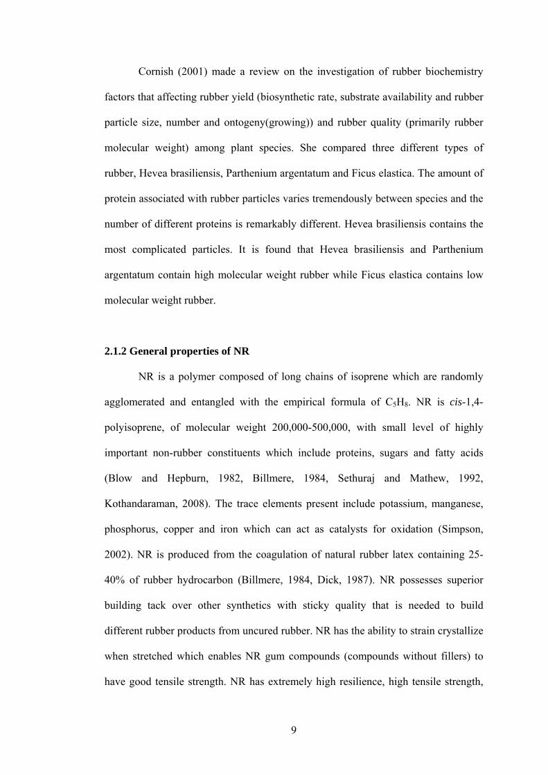
Nakason et al., 2005). Figure 2.2 shows general repeat unit of isoprene of natural
rubber. For this structure, two carbon atoms are joined together by a double bond and
locked in a rigid structure. Because of the presence of an asymmetric carbon atom,
cis (two same groups attached to each carbon are in the same sides) and trans (two
same groups attached to each carbon are in the opposite sides) forms are possible.
Figure 2. 2 Repeat unit of NR (polyisoprene) (Simpson, 2002)
2.1.3 Mooney viscosity and gel content
Mooney viscosity is a measure of the viscosity of a raw rubber or rubber
compound determined in a Mooney shearing disk viscometer. Mooney viscosity was
first used in technically classified rubber for grading standard rubber (Simpson,
2002). For raw rubber, the measured viscosity is done at temperature of 100 oC with
one minute preheating and four minutes running test which is written in short
ML(1+4)100 (Ehabé et al., 2005). Mooney viscosity of rubber sample relates roughly
to the rubber’s average molecular weight. It also reflects the molecular weight
distribution and the amount of network structure that is exhibited in rubber (Blow
and Hepburn, 1982, IRI, 1998).
Bhowmick et al. (1986) investigated the effect of gel and molecular weight
on properties of natural rubber. Samples with different gel contents but similar
11
molecular weights and samples with the same gel content with varying molecular
weights prepared from the extraction of natural rubber. The gel content was varied
from 1.5 to 29% and molecular weight from 1 x 10⁵ to 9.9 x l05 g mol- 1. Samples
with higher molecular weight and higher gel content showed better stress-strain
properties. Chenal et al. (2007) investigated the strain-induce crystallization (SIC) of
natural rubber compounds which focus on molecular weight between physical
entanglements. It showed that natural rubber is essentially constituted of cis-1,4
polyisoprene which stereoregularity allows rapid crystallization when it is stretched
more than 300% of its original length. This strain-induced crystallization (SIC), gives
NR a self-reinforcement characteristics, and increase in crosslink density which
reduced the NR matrix mobility and delays the orientation of the crystallites during
the stretching process.
2.1.4 Wallace rapid plasticity (Po) and plasticity retention index (PRI)
Plasticity can be described as ease of deformation of rubber so that highly
plastic rubber is determined by one that deforms or flow easily (Brown, 1986). The
PRI reflects the vulnerability of the product to thermo-oxidation, whereas Po
provides the viscosity of an average for the range of shear rates throughout the
rubber of the raw material. Plasticity is determined by the Wallace plastimeter which
used as quality control for most natural rubber product (Bonfils et al., 1999).
12
2.2 Fillers
2.2.1 Definition and classifications
The concept of cost reduction by use of filled materials has been known
throughout the ages (Blow and Hepburn, 1982, Lutz and Grossman, 2001). In
general, fillers are defined as materials (can be in the form of solid, liquid, or gas)
that are added to the formulation to lower the compound cost. The appropriate
selection and optimization of such materials, not only lower the price but improved
other properties such as processing and mechanical behaviour (Lutz and Grossman,
2001).
For effective utilization of fillers, a complete understanding of individual
characteristics is essential. Each class of fillers appears to exhibit specific
characteristics which suited for the given application. For example, aluminium
powder is used to improve the resistance of the compounds toward heat, ozone and
gamma irradiation (Vinod et al., 2002), calcined clays for electrical properties
(González et al., 2000). Although these fillers retain their inherent characteristics,
very significant differences are often observed, depending on the molecular weight,
compounding technique, and the presence of other additives in the formulation.
Therefore, once the basic property requirements are established, the optimum filler
type and loading for cost/performance balance can be determined (Wypych, 2000,
Lutz and Grossman, 2001).
Fillers can be classified in many different ways, ranging from their shapes
(sphere, rods, ribbons, flakes) to specific characteristics (conductivity, fire
retardancy)(Wypych, 2000). For simplicity, fillers can be classified in two
categories: extenders (primarily occupies space and is mainly used to lower the
13
formulation cost) and functional/reinforcement materials (has a definite and required
function in the formulation apart from cost) (Lutz and Grossman, 2001). In general,
an ideal extender should:
- be spherical to permit retention of anisotropic properties
- have an appropriate particle size distribution for particle packing
- no chemical reactivity with the polymer or additives
- have a low specific gravity
- have a desirable refractive index and color
- low in cost.
Common extenders are limestone, kaolin clay and talc. For functional group,
precipitated silica and carbon black are commonly used among commercial fillers
and these are extensively used when high strength is essential.
2.2.2. Fillers characteristics
Fillers are added to the matrix to improve the properties (tensile strength, tear
resistance, abrasion resistance) of composites (Blow and Hepburn, 1982, Dick,
1987). Fillers can constitute either a major or a minor part of a composite. Modulus
of rubbers is increased by the incorporation of reinforcing fillers such as carbon
black or silica. The key elements of rubber reinforcement with fillers are particle
size, surface area, structure, dispersion and interaction between the surface of the
reinforcing material and the rubber (IRI, 1998). The structure of filler particles
ranges from precise geometrical forms, such as spheres, hexagonal plates, or short
fibers, to irregular masses. Extensive usage of particulate fillers in many polymers is
for the enhancement in stiffness, strength, dimensional stability, toughness, heat
distortion temperature, damping, impermeability, and cost reduction (Herman, 2003).
14
2.2.2.1 Particle size
Average filler’s particle size is one of the most important characteristics in predicting
the function for a given filler to impart the properties of rubber. In general, the
smaller the average particle size of a filler, the higher the degree of reinforcement
imparted to the vulcanizate. Improvement in reinforcement means the tensile,
modulus, abrasion resistance, and tear resistance showed very large increase in
properties. Large particles of fillers caused severe cracking. Fillers with average
particle sizes range (1 to 5 microns) are dilution fillers which do not significantly
improve or have a negative effect on the physical properties of the vulcanizate
provided the loadings are not too high (Dick, 1987). However, due to increases in
both surface area and volume ratio with a reduction in filler particle size, finer
particles are prone to agglomerate for the conservation of internal energy and are
more difficult to be dispersed (Herman, 2003).
2.2.2.2 Particle shape and structure
The structure and particle shape of a filler are also important. Structure
relates to the aggregation of particles. Carbon blacks tend to have much higher
structure than inorganic fillers. The structure of most inorganic fillers is lower than
carbon black and tends to break up easily during mixing. Carbon blacks with the
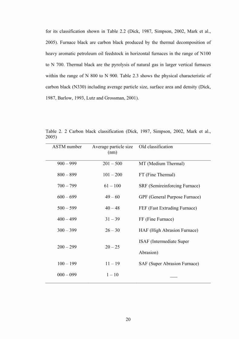
same particle size but with different structures will give different physical properties
in rubber. A higher structure carbon black (Figure 2.5(b)) in a rubber compound will
impart less extrudate shrinkage, swell less on extrusion and impart a higher modulus
than a lower structure carbon black (Dick, 1987). Figure 2.3 shows the basic particle
shapes and typical aspect ratios which is the ratio of the longest length of a particle to
it thickness. In general, a high aspect ratio material is more difficult to process and
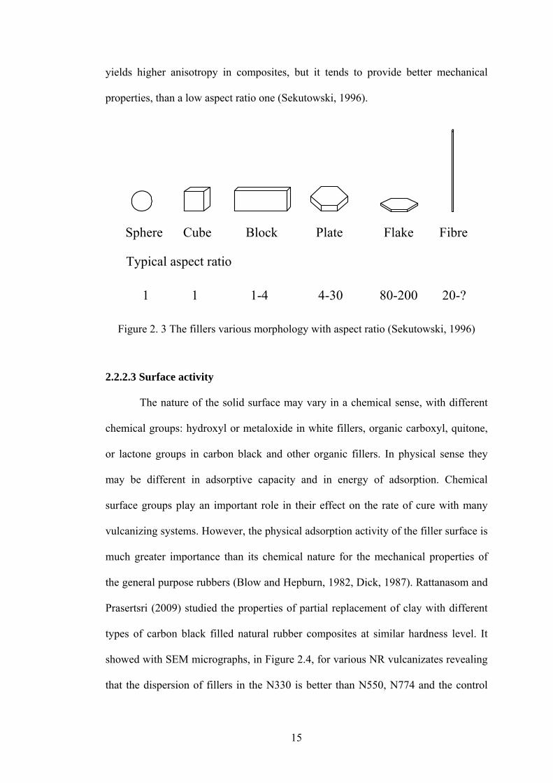
15
Sphere Cube Block Plate Flake Fibre
Typical aspect ratio
1 1 1-4 4-30 80-200 20-?
yields higher anisotropy in composites, but it tends to provide better mechanical
properties, than a low aspect ratio one (Sekutowski, 1996).
Figure 2. 3 The fillers various morphology with aspect ratio (Sekutowski, 1996)
2.2.2.3 Surface activity
The nature of the solid surface may vary in a chemical sense, with different
chemical groups: hydroxyl or metaloxide in white fillers, organic carboxyl, quitone,
or lactone groups in carbon black and other organic fillers. In physical sense they
may be different in adsorptive capacity and in energy of adsorption. Chemical
surface groups play an important role in their effect on the rate of cure with many
vulcanizing systems. However, the physical adsorption activity of the filler surface is
much greater importance than its chemical nature for the mechanical properties of
the general purpose rubbers (Blow and Hepburn, 1982, Dick, 1987). Rattanasom and
Prasertsri (2009) studied the properties of partial replacement of clay with different
types of carbon black filled natural rubber composites at similar hardness level. It
showed with SEM micrographs, in Figure 2.4, for various NR vulcanizates revealing
that the dispersion of fillers in the N330 is better than N550, N774 and the control
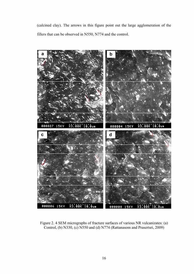
16
(calcined clay). The arrows in this figure point out the large agglomeration of the
fillers that can be observed in N550, N774 and the control.
Figure 2. 4 SEM micrographs of fracture surfaces of various NR vulcanizates: (a) Control, (b) N330, (c) N550 and (d) N774 (Rattanasom and Prasertsri, 2009)
17
2.2.2.4 Matrix-filler interaction
The interaction between rubber and filler give significant effect on
reinforcement of filled rubber composites. The rubber–filler interactions strongly
depend on their characteristic and their amount. Matrix-filler interaction showed the
compatibility between rubber and filler while filler-filler interaction occur due to the
bonding between the fillers and their ability to form networks which are aggregates
(agglomerates) (Kohls and Beaucage, 2002). The interaction in the rubber
composites occurs by chemical and physical combination interactions (Mark et al.,
2005).
In general, reinforcement can obtained through applied stress transferred
from polymer to fillers. Through more uniform distribution of stress from a large
number of extremely small flaws, weak points or cracks that tend to open up at
points of high local stress concentration. The unique reinforcing capacity of carbon
black may be due to its surface adsorption characteristics. These relatively strong
bonds limit further slippage and contribute to the strength of vulcanisate (Blow and
Hepburn, 1982). Carbon black has been found to offer substantial improvement in
the mechanical properties of rubber due to its good compatibility with rubber.
Practically, the crosslink density in rubber vulcanizates increases significantly with
increasing carbon black content. These crosslinks control extensibility of the rubber
chains caused by swelling and make it more difficult for oil to diffusion into the gaps
between rubber molecules and decrease the swelling percentage (Mostafa et al.,
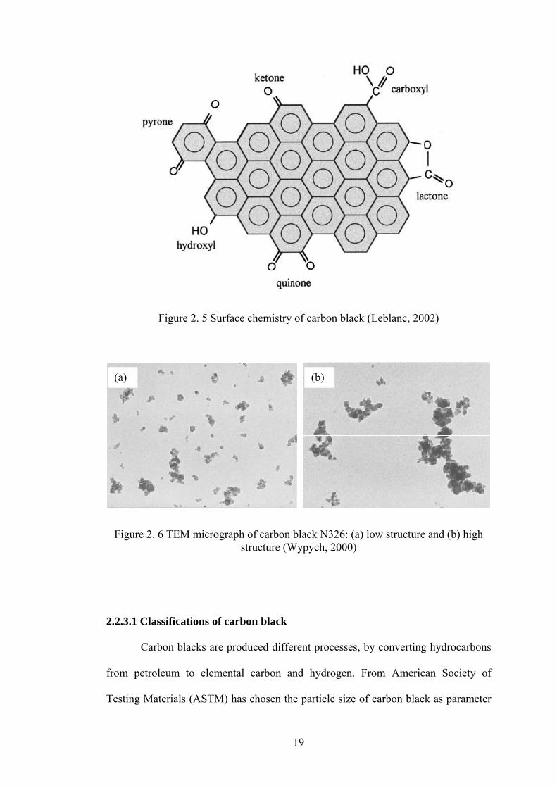
2009) which showed the increase in filler-rubber matrix interaction. Leblanc (2002)
reviewed the rubber-filler interactions and rheological properties of rubber filled
carbon black and silica composites. It showed filler particle size and structure as
18
primary parameters, and surface characteristics as secondary particle parameters.
Figure 2.5 shows the functional groups of carbon black on surface chemistry which
results in high interaction to rubber matrix. A review of characterization dispersion
state of filler and polymer-filler interactions in rubber-carbon composites was done
by Karásek and Sumita (1996). The uniform dispersion of carbon black throughout
the rubber matrix is very important for rubber compounding to achieve optimum
vulcanizate properties and the degree of dispersion is a factor which ultimately
controls the physical properties of the composite.
2.2.3 Carbon black
Carbon black is an amorphous carbon of quasi-graphitic structure. The
particles range from 10 nm to 500 nm in diameter. A common value used for the
density of carbon black in rubber is 1.80 and carbon blacks consist of 90 to 99
percent elemental carbon. The other major constituents are hydrogen and oxygen.
Carbon blacks are produced by converting either liquid or gaseous hydrocarbons to
elemental carbon and hydrogen by partial combustion or thermal decomposition.
Carbon black particle surfaces have quinine, lactone, carboxyl, and other organic
functional groups, shown in Figure 2.6, which improve the interaction between the
carbon black and rubber (Blow and Hepburn, 1982, Dick, 1987, Barlow, 1993, Kohls
and Beaucage, 2002, Leblanc, 2002, Simpson, 2002, Mark et al., 2005). Figure 2.6
showed the TEM micrograph of carbon black N326 in (a) low structure and (b) high
structure. A higher structure carbon black in a rubber compound will impart less
extrudate shrinkage, swell less on extrusion and impart a higher modulus than a
lower structure carbon black.
19
(a)
Figure 2. 5 Surface chemistry of carbon black (Leblanc, 2002)
Figure 2. 6 TEM micrograph of carbon black N326: (a) low structure and (b) high
structure (Wypych, 2000)
2.2.3.1 Classifications of carbon black
Carbon blacks are produced different processes, by converting hydrocarbons
from petroleum to elemental carbon and hydrogen. From American Society of
Testing Materials (ASTM) has chosen the particle size of carbon black as parameter
(b)
20
for its classification shown in Table 2.2 (Dick, 1987, Simpson, 2002, Mark et al.,
2005). Furnace black are carbon black produced by the thermal decomposition of
heavy aromatic petroleum oil feedstock in horizontal furnaces in the range of N100
to N 700. Thermal black are the pyrolysis of natural gas in larger vertical furnaces
within the range of N 800 to N 900. Table 2.3 shows the physical characteristic of
carbon black (N330) including average particle size, surface area and density (Dick,
1987, Barlow, 1993, Lutz and Grossman, 2001).
Table 2. 2 Carbon black classification (Dick, 1987, Simpson, 2002, Mark et al., 2005)
ASTM number Average particle size (nm)
Old classification
900 – 999 201 – 500 MT (Medium Thermal)
800 – 899 101 – 200 FT (Fine Thermal)
700 – 799 61 – 100 SRF (Semireinforcing Furnace)
600 – 699 49 – 60 GPF (General Purpose Furnace)
500 – 599 40 – 48 FEF (Fast Extruding Furnace)
400 – 499 31 – 39 FF (Fine Furnace)
300 – 399 26 – 30 HAF (High Abrasion Furnace)
200 – 299 20 – 25 ISAF (Intermediate Super
Abrasion)
100 – 199 11 – 19 SAF (Super Abrasion Furnace)
000 – 099 1 – 10 ___
21
Table 2. 3 Physical characteristics of carbon black (N330) (Dick, 1987, Barlow, 1993, Lutz and Grossman, 2001)
Parameter Carbon black (N330)
Average particle size (m) 0.026 – 0.03
Surface area (m2/g) 98.9
Density (g/cm3) 1.8
2.2.3.2 Effects of carbon black on rubber composites properties
The primary purpose for using carbon black with rubber for reinforcement
which included the enhancement of tensile strength (TS), modulus, abrasion, and tear
resistance. Carbon blacks affect both rubber processing and vulcanizate properties
due to physical properties (particle size, surface area and character, and structure)
and chemical interaction. Probably the most important property of a carbon black is
the surface that is accessible for reaction with rubber molecules per unit of weight.
Carbon black aggregate particles can be tightly clustered together like a bunch of
grapes, or the same number of particles can be arranged in more open fashion, giving
greater bulk, in a manifestation called high structure (Gent, 2001, Arroyo et al., 2003,
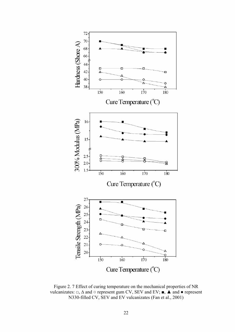
Choi et al., 2003). Fan et al. (2001) studied the effect of curing temperature on
properties of gum and N330-filled natural rubber vulcanizate with conventional
(CV), semi-efficient (SEV), and efficient (EV) cure systems. The presence of carbon
black in natural rubber vulcanizates increased their tensile strength, 300% modulus,
and hardness as shown in Figure 2.7.
22
Figure 2. 7 Effect of curing temperature on the mechanical properties of NR vulcanizates: □, ∆ and ○ represent gum CV, SEV and EV; ■, ▲ and ● represent
N330-filled CV, SEV and EV vulcanizates (Fan et al., 2001)