Effect of damped outriggers arrangement on the seismic...
32
* Corresponding author. Azadi St., Tehran, Iran. Email: [email protected]; Tel.: +98 21 66164214; Fax: +98 21 66014828; Mobile number: +98 912 377 1857. Email addresses: [email protected], [email protected]. Effect of damped outriggers arrangement on the seismic response of high-rise steel structures Hamid Asadi Ghoozhdi a and Masood Mofid a,* a. Department of Civil Engineering, Sharif University of Technology, Tehran, Iran Abstract. Recently, a novel structural system, which is defined as damped outrigger system, has been proposed to control dynamic vibration of tall buildings. This paper examines seismic performance of tall buildings involving multiple outriggers equipped with viscous dampers. In this respect, a dual structural system (braced moment frame) is selected as a bare structure. In addition, the number and position of outriggers are assumed to be variable along the height of structure. Nonlinear response history analysis (RHA) is performed to evaluate the efficiency of damped-outrigger system under eight scaled ground motions. The results are presented based on the average of all ground motions. The mean inter-story drift ratio and maximum base shear force are compared in order to determine the best arrangement of damped outriggers. Conclusively, based on minimizing base shear force, the optimal location of damped outriggers under dynamic excitation is generally the same as that made for conventional outriggers. According to the inter-story drift ratio parameter, it is recommended to place one of the outriggers at the roof level. KEYWORDS: Damped outrigger; Viscous damper; Outriggers arrangement; High-rise steel structures, Inelastic dynamic time-history analysis 1. Introduction Construction of towers and tall buildings has been favored among humankind from the beginning of civilization. The purpose of the first towers like castles was defending cities. In the 19 th century, development of high-rise structures was a solution to commercial and residential needs [1]. Since 1970, outrigger systems have been often used in tall buildings [2]. This system includes two types of structural systems; the first type is a central core such as steel braced frame, steel shear wall, concrete core and concrete shear wall. The second type is an outrigger system such as girders and truss connecting the central core to the perimeter columns. The optimum position of outrigger system is a major challenge for structural engineers. Furthermore, architectural limitations should be considered. As a common solution, outriggers are placed at stories with mechanical equipment. Outrigger system usually can be applied in two sequential stories in order to increase the stiffness of structure [1,2]. Damping is a major factor in controlling the vibration of tall buildings located in seismic regions. Based on the recent investigations on different buildings, damping ratio of tall buildings is lower in comparison to the others. Moreover, damping ratio depends on the amplitude of the earthquake to the point that increasing the intensity of
Transcript of Effect of damped outriggers arrangement on the seismic...
* Corresponding author. Azadi St., Tehran, Iran. Email: [email protected];
Tel.: +98 21 66164214; Fax: +98 21 66014828; Mobile number: +98 912 377 1857.
Email addresses: [email protected], [email protected].
Effect of damped outriggers arrangement on the seismic response
of high-rise steel structures
Hamid Asadi Ghoozhdia and Masood Mofid
a,*
a. Department of Civil Engineering, Sharif University of Technology, Tehran, Iran
Abstract. Recently, a novel structural system, which is defined as damped outrigger
system, has been proposed to control dynamic vibration of tall buildings. This paper
examines seismic performance of tall buildings involving multiple outriggers equipped
with viscous dampers. In this respect, a dual structural system (braced moment frame) is
selected as a bare structure. In addition, the number and position of outriggers are
assumed to be variable along the height of structure. Nonlinear response history analysis
(RHA) is performed to evaluate the efficiency of damped-outrigger system under eight
scaled ground motions. The results are presented based on the average of all ground
motions. The mean inter-story drift ratio and maximum base shear force are compared
in order to determine the best arrangement of damped outriggers. Conclusively, based
on minimizing base shear force, the optimal location of damped outriggers under
dynamic excitation is generally the same as that made for conventional outriggers.
According to the inter-story drift ratio parameter, it is recommended to place one of the
outriggers at the roof level.
KEYWORDS: Damped outrigger; Viscous damper; Outriggers arrangement; High-rise
steel structures, Inelastic dynamic time-history analysis
1. Introduction
Construction of towers and tall buildings has been favored among humankind from the
beginning of civilization. The purpose of the first towers like castles was defending
cities. In the 19th
century, development of high-rise structures was a solution to
commercial and residential needs [1].
Since 1970, outrigger systems have been often used in tall buildings [2]. This system
includes two types of structural systems; the first type is a central core such as steel
braced frame, steel shear wall, concrete core and concrete shear wall. The second type is
an outrigger system such as girders and truss connecting the central core to the
perimeter columns. The optimum position of outrigger system is a major challenge for
structural engineers. Furthermore, architectural limitations should be considered. As a
common solution, outriggers are placed at stories with mechanical equipment. Outrigger
system usually can be applied in two sequential stories in order to increase the stiffness
of structure [1,2].
Damping is a major factor in controlling the vibration of tall buildings located in
seismic regions. Based on the recent investigations on different buildings, damping ratio
of tall buildings is lower in comparison to the others. Moreover, damping ratio depends
on the amplitude of the earthquake to the point that increasing the intensity of

earthquake provides more level of damping [3]. In addition, analysis and design of tall
buildings should be performed under several levels of ground motion intensity. By
using an appropriate device as an additional damping source, it is feasible to achieve
higher levels of damping. Subsequently, the materials used in the structural elements
may be reduced [4].
To improve the structural performance of outrigger system, the location and number
of outriggers should be adjusted. The optimum location has been computed mainly for
static condition. There are few number of references available on dynamic response of
outrigger systems. For uniform lateral loading and considering rigid outriggers,
optimum location has been computed in several cases. In the one-outrigger case, the
optimum location was at 0.455H from the top of the structure, where H is the height of
the cantilever model [5]. For a uniform cantilever beam equipped with two rigid
outriggers, optimum locations were at 0.312H and 0.685H from the top, where H had
the same definition [6]. Response of outrigger system with variable stiffness of the
cantilever model along the height of structure was studied under several lateral load
distributions. It was concluded that the location of outrigger at the vicinity of the base
level was not efficient enough. Besides, the effect of lateral load distribution on
outrigger position was negligible [7]. In the next study, the influence of outrigger
flexibility in regards to the best position of multi-outrigger system subjected to uniform
lateral loading was discussed. In addition, the effect of outrigger flexibility relevant to
the various structural parameters such as core moment distribution, top drift and optimal
position was investigated. The more flexible outriggers are, their optimum position
locates lower. In addition, using outrigger systems with less rigidity caused vital
reduction in structural efficiency [8]. Optimal design of high-rise structures equipped
with multiple conventional outriggers was investigated under two prevalent lateral load
distributions. Furthermore, variations of some structural parameters like fundamental
period of structure versus location of outriggers have been achieved. It was found that
the optimum location of outriggers in tall buildings subjected to uniform lateral loading
is approximately 5% lower than that of structures subjected to triangular lateral load
distributions [9].
In recent years, damped outrigger systems have been proposed for tall buildings.
This structural form is introduced as a new philosophy to control the induced vibration
in tall buildings. Based on this concept, using damped outriggers may lead to higher
levels of damping. In this system, combination of outriggers and viscous dampers can
be applied in several ways. For instance, a viscous damper can be connected to the end
of outriggers or located in them. To evaluate the efficiency of damped outrigger, two
actual buildings were considered. It was concluded that the additional damping ratio of
those structures subjected to a 100-year wind vibration was estimated between 5.2% and
11.2% for each principal direction. Consequently, the amount of structural material
reduced and the net area of each story increased [10].
The efficiency of damped outrigger systems is also verified by experimental study.
This investigation showed that the amount of supplementary damping increases by
adding viscous dampers at the end of outriggers. By performing a test with a shaking
table, the seismic performance of eight-story steel structure with multiple outriggers
was investigated for the two cases. In the first case, the connections between outriggers
and perimeter columns were pinned, whereas in the second, outriggers are equipped
with viscous dampers. It was found that the efficiency of viscous damper under
moderate earthquakes is nearly equal to the bare structures. However, as earthquake
intensity increases, the influence of viscous damper becomes more obvious [11].
A simplified model was suggested for assessing the seismic behavior of tall buildings
equipped with hysteresis damped outriggers. The effect of outriggers on the central core
was considered based on the applied concentrated moments [12]. A simple beam-
damper model has been developed to obtain the exact solution for damped outrigger
systems. Furthermore, this includes a cantilever beam and rigid horizontal element
model as the main structure and the outrigger, respectively. Outrigger was connected to
the cantilever beam by using viscous dampers. Dynamic characteristics of the model
have been computed based on the analytical solution. Thus, the optimal location of
damped outrigger and optimum value of damping coefficient were determined [13]. The
cantilever beam model was improved by considering the effect of axial stiffness of
perimeter columns [14]. A general solution for performance evaluation of tall buildings
with multiple damped and conventional outriggers was presented. As the results of a tall
building with multiple damped or undamped outriggers, the proposed method was
capable of providing an optimally parametric design with respect to the position of
outriggers, damping, and core-to-column and core-to-outrigger stiffness ratio [15].
Huang and Takeuchi obtained analytical solution for the dynamic response evaluation
of a single-damped-outrigger system and determined the optimal outrigger locations and
damper sizes to minimize response. The optimal outrigger location was between 0.5H
and 0.8H from the base. Besides, The optimum values of outrigger location and damper
size increase with building height [16]. The seismic energy distribution through the core
and outriggers of a 60‐ story building with conventional and damped outriggers was
examined under small, moderate, strong, and severe long‐ period earthquakes. It was
revealed that, as the ground motion becomes stronger, viscous dampers effectively
reduce the potential of damage to the structure compared to the conventional outriggers
[17].
To increase damping of the outrigger system, other passive energy dissipators like
buckling-restrained brace (BRB) are also implemented [18-21]. This element limits the
maximum force that the outrigger can develop [18]. It was observed that location of the
plastic hinges in core-wall is influenced by the BRB outriggers [20]. Moreover, a
response modification factor of 5 is recommended for the RC core-wall with BRB [21].
Most of the above-mentioned studies have mainly focused on the linear systems.
Moreover, these investigations are commonly limited to single outrigger structures. In
this paper, seismic response of tall buildings involving multiple damped outriggers is
studied. Two important parameters, number and location of outriggers, are considered
to examine the performance of damped-outrigger system. To this purpose, a dual
structural system consists of a moment frame and a braced core has been selected as the
reference model. These steel frames are modeled with geometric and material nonlinear
behavior. Moreover, based on including outriggers, two general cases are considered. It
should be noted that the position of outrigger is varied along the height of structure. In
addition, the number of outriggers is assumed to be one, two or three. Nonlinear time-
history analysis is applied to assess the performance of damped-outrigger system. These
structures responses including maximum story drift and maximum base shear force are
compared to determine the best position of outriggers.

2. Description of the models
2.1 Preliminary design
Three structural models having 20, 30 and 40 stories are considered to evaluate the
seismic performance of damped outrigger system. These models are two-dimensional,
regular and interior frames. The elevation view of the models is depicted in Figure 1. A
dual structural system, which includes a moment frame and a braced core, has been
selected. Preliminary design of steel bare structures (without outrigger) is performed
according to the Iranian Code of Practice for Seismic Resistant Design of Buildings
(Standard No. 2800) and the Iranian National Building Codes (Parts 6 and 10).
Furthermore, design of steel frames is performed based on the Load and Resistance
Factor Design (LRFD) method mentioned in AISC-LRFD 2010 [22] and AISC 341-10
[23]. Therefore, the effect of outriggers in the initial design of structural members has
been ignored. As seen in Figure 2, inter-story drift limits may not be satisfied in the bare
structures under linear response spectrum analysis. In the preliminary design, this
defection will be improved by appropriate arrangement of damped outriggers. The aim
of this paper is obtaining the best solution for this problem.
The structural frames have bays with an equal width of 5 m and a typical height of
3.2 m at each story. The structures are assumed to be located in Tehran which is a high
seismic region (with zone design acceleration corresponding to 475 years return period,
A = 0.35) on soil type C according to NEHRP classification. The gravity loads are 7.5
kN/m2 and 2.5 kN/m
2 for dead and live loads, respectively. The effective seismic mass
of the structure was considered to be dead load plus 20% of the live load. The fully
restrained beam to column connections in steel moment resisting frames have been
considered. In addition, nonlinear beam-column elements with pinned end connections
were applied for the braces. The box profiles are selected for columns and braces and
HEB profiles are used for beams. The sections of structural components are shown in
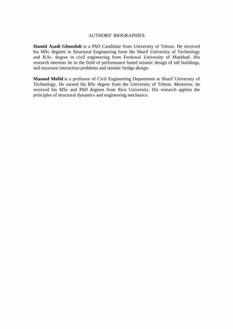
Table 1.
Figure 1. [Near Here]
Table 1. [Near Here]
Figure 2. [Near Here]
2.2 Nonlinear modeling
In order to investigate the seismic responses of structures equipped with damping
systems, according to the ASCE/SEI 7-10 [24] recommendation, nonlinear response
history procedure is suggested. For this purpose, high-rise structures with damped
outriggers should be modeled with nonlinear material behavior. Elastic-linearly plastic
behavior is utilized for steel material. Properties of steel are defined with the yield stress
of 235 MPa, initial elastic modulus of 200 GPa and strain-hardening stiffness ratio
equals to 2%. The ‘Steel01’ material which is defined in the library of Open System for
Earthquake Engineering (OpenSees) platform [25] is applied to model behavior of
steel material.
Braces, beams and columns have been modeled with the force-based beam-column
element (FBE) in the OpenSees framework. The formation of plastic hinges is captured
by utilizing the fiber modeling approach (distributed plasticity). The beams and
columns of the structure are modeled with single force-based beam-column element.
Five integration points along the member length are considered and each section at
the beam-column ends is discretized to 200 fibers. Lateral buckling of the brace
elements has been applied by considering an initial imperfection for the braces. Based
on the recommendations of Uriz and Mahin [26], parameters needed for modeling steel
brace are specified (including number of segments, integration points and value of
initial camber). Accordingly, each brace element was modeled by subdividing its length
into 2 force-based fiber element in order to contemplate the simplest initial imperfection
curve. The initial imperfection is assumed to be 0.1% of the member length at the
middle of brace element in this study. It should be noted that the number of integration
points and fibers selected for brace elements is the same as that used for beam-column
members.
2.3 Inherent damping
Damping is a structural factor to evaluate the amount of energy dissipated by structure.
This parameter causes considerable reduction in dynamic vibration of tall buildings.
There are three sources to provide damping: inherent, hysteretic and additional
damping. Inherent damping depends on some characteristics of the building itself such
as foundation, structural system, material, non-structural components and the cladding.
Moreover, the height of buildings plays a significant role in the level of damping
contributed to the response of structure. According to these factors, determination of
inherent damping is complicated [4]. Hysteretic damping which is a primary source of
damping developed by formation plastic hinges at member ends. The third source which
is defined by adding a device to the building is supplementary damping. In this paper,
the effect of supplementary damping on the behavior of structures is modeled explicitly.
Section 2.4 of PEER/ATC-72-1 [3] puts forward some recommendations for modeling
the material damping. Measurements indicated that damping value in tall buildings is
lower compared to low-rise structures as illustrated in Figure 3. Therefore, using classic
damping ratios suggested by available guidelines, as well as, codes is non-conservative.
By using the following recommendations for damping ratio of high-rise steel structures
in Figure 3, this value is determined. Note that this damping ratio is suggested for
nonlinear response history analyses. Using Rayleigh method, the material damping is
assigned to the first mode and the mode in which the cumulative mass participation is at
least 90%.

Figure 3. [Near Here]
2.4 Verification of linear structures
By a modal analysis, fundamental periods of structures are presented in Table 2. Modal
analysis is established by Finite Element Programs (SeismoStruct [27] and OpenSees).
It must be regarded that the fundamental period of vibration is determined without
considering the effect of outriggers. In other words, these periods are related to bare
structures. It can be found that the models periods computed based on two computer
programs are the same. Therefore, the linear models constructed in OpenSees
framework are verified.
Table 2. [Near Here]
3. Ground motion Excitations
3.1 Selection of the earthquake records
The ground motions selected in this study include eight earthquake records. These
records are chosen from the earthquake excitations mentioned in Appendix-C of FEMA
440 [28] and Appendix-A of FEMA P695 [29]. Furthermore, the proposed records are
related to the site class C according to the NEHRP Site Classification (average shear
wave velocity in the top 30 m: 360-760 m/s). In addition, the station selected for each
earthquake is related to a far-field record. Thus, Table 3 shows the ensemble of eight
ground motions used in the nonlinear response history analysis. In this table, scaling
factors of the ground motions are given based on the technique presented in section 3.2.
Earthquake records were obtained from the PEER ground motion database [30].
Table 3. [Near Here]
3.2 Scaling the earthquake records
According to the ASCE/SEI 7-10 standard, records should be scaled in a way that the
design response spectrum for the site class C does not get greater than the average of the
acceleration spectra for the ground motions. Periods ranging from 0.2T to 1.5T must be
controlled, where T is the fundamental period of structure. Comparison between mean
linear response spectrum of the eight ground motion and target spectrum is depicted in
Figure 4; and the pseudo-acceleration response spectrum of the ground motion is
determined.
Figure 4. [Near Here]
4. Specifications of damped outriggers
4.1 Configuration of damped outriggers
The components of damped outriggers in each structural model are shown in Figure 5.
Basically, the outrigger set is located at two adjacent stories and consists of steel brace
element and viscous damper. Bracing members used in the outrigger system are
modeled similar to braces of reference structure. Therefore, the possibility of lateral
buckling for these elements has been also investigated using the method mentioned in
section 2.1.
Viscous damper is a type of viscoelastic damping systems. These devices are
installed between two specific points of the structure and work based on the relative
velocity of the points. Viscous dampers are installed as diagonal braces at peripheral
bays. The central braced core is connected to viscous dampers by steel bracing
members. Damper system is modeled by using Maxwell material. This model includes a
viscous damper and a spring connected in series. Spring element represents the elastic
stiffness of the link used to install the viscous damper in target frame.
Figure 5. [Near Here]
4.2 Determination of damped outrigger parameters
It is essential to compute the effective parameters of damped outrigger system before
evaluating the impact of outrigger location on response of tall buildings. For this reason,
characteristics of the brace element, as well as, the viscous damper should be obtained.
In the one-outrigger case, the outrigger placed at mid-height, in order to determine the
properties of the damped outrigger. In other cases, the first outrigger is fixed at middle
stories and the second one is located at roof level. Based on these assumptions, the
designed section for steel brace element is selected according to the results of linear
response spectrum analysis presented in Table 4. Moreover, the damping coefficient
(Cd) is calculated by conducting nonlinear response history analysis (RHA) at the
design earthquake (DBE) level. The influence of damping coefficient on maximum
seismic response of damped outrigger system was previously examined by
some researchers [10, 16]. Hence, it is necessary to iterate the viscous resistance (Cd) of
the dampers to determine its optimum value. The variation of base shear force with the
damping coefficient for 20-story and 30-story structures subjected to Hector Mine
earthquake is computed and plotted in Figure 6. It can be seen that there is an optimum
value for Cd that can achieve the best performance. Moreover, mid-height damped
outrigger has better seismic performance than the case of damped outrigger at base
level. This observation is in agreement with the results presented by Huang and
Takeuchi [16]. The results of the parametric study, calculated based on RHA, lead to
optimum coefficient of viscous damper (Table 4). Note that damping exponent is
assumed to be 1 and viscous damper behavior is linear.
Figure 6. [Near Here]
Table 4. [Near Here]
4.3 Studied positions for damped outriggers
Several positions opted for damped outriggers in various cases including one, two and
three outriggers. In the one-outrigger case, the position of outrigger moves upward
along the height of structure from the base. Thus, the number of cases analyzed in the
structures with 20, 30 and 40 stories equals to 10, 15 and 20, respectively. Determining
the best position of damped outriggers, primarily in structures with more than one
outrigger, involves a specific condition which is related to the outriggers arrangement.
Therefore, in the two-outrigger case, it is assumed that one of these outriggers has been
located in the lower half and the other one has been placed approximately at the upper
half of the structure’s height. For models equipped with three outriggers, the first
outrigger is located in the lower one third of the height, the position of second outrigger
is varied in the middle one third and the third outrigger is located at upper one third of
the building’s height. This case is only considered for 30-story and 40-story models. For
instance, these studied positions are illustrated for 40-story structure in Figure 7.
Figure 7. [Near Here]
5. Optimum arrangement of damped outriggers
5.1 Definition of key parameters
To investigate the performance of damped outrigger systems, two significant parameters
comprised of base shear force and inter-story drift ratio have been considered for
determination of optimum arrangement of outrigger. The first parameter is base shear
force which can be demonstrated by the amount of lateral loads carried by the structural
form. Inter-story drift ratio is chosen as the second parameter which is limited to
definite values by guidelines. In order to evaluate predefined parameters, nonlinear
RHA for each ground motion should be performed. The presented results are mean
values of 8 earthquake ground motions. For all structures, this analysis is also
performed without considering the effect of outriggers. As mentioned before, one-
outrigger systems located at two adjacent stories labeled with their lower story number
are depicted in the following figures. According to the ASCE/SEI 7-10 [21] for
buildings with long-period, allowable drift ratio is assumed to be equal to 0.02.
5.2 Base shear force
The effect of maximum base shear force on the arrangement of damped outriggers is
studied. For structures with one outrigger, the effect of outrigger location on the
maximum base shear force is shown in Figure 8. It is found that the middle stories are
the optimum positions for the damped outrigger in each model. The optimum location
of damped outrigger of 30-story model is slightly higher compared to other structures,
possibly due to the greater aspect ratio. This conclusion is in agreement with the optimal
outrigger location reported by Huang and Takeuchi [16] for three different outrigger
frame buildings based on lateral displacement and story drift. It should be mentioned
that inter-story drift ratio is directly related to the resulting base shear of structure for
elastic systems.
Figure 8. [Near Here]
In Figure 9, structures equipped with two outriggers are investigated. The results are
reported in a way that the position of lower outrigger is fixed and the variation of
maximum base shear force versus upper outrigger location is plotted. The results of
each structural model are obtained as follows:
For 20-story frame, the optimum position of lower outrigger is located in 7th
story. Besides, position of upper outrigger has less effect on minimizing base
shear force. Therefore, it could be concluded that using two outriggers may not
provide more impressive efficiency compared to one outrigger in this structure.
For other structures, the optimum position of both lower and upper outriggers
are approximately at 0.33 and 0.66 of the structural height, respectively.
Note that similar to the one-outrigger case, two outriggers are placed slightly
higher for 30-story structure.
It is observed that the optimal location of lower outrigger is nearly at the mid-
height when the upper outrigger is placed at the roof level. This trend is
generally seen for all buildings with different number of stories. This
observation is compatible with the results of the study carried out by Fang et al.
[15] for maximum modal damping ratio of structures equipped with two damped
outriggers.
Figure 9. [Near Here]
Evidently, Figure 10 demonstrates the optimum positions of three outriggers. To
determine the optimum positions of outriggers, it is assumed that the locations of upper
and lower outriggers are fixed, as well as, base shear diagram is depicted versus
position of middle outrigger. For 30-story frame, the best positions of first, second and

third outriggers are suggested to be at 9th
story, 15th
story and 23rd
story, respectively.
Further observation reveals that in three-outrigger case, the best locations of damped
outriggers are nearly at 0.25, 0.5 and 0.75 of the structural height. Thus, optimum
location of damped outriggers based on minimizing the base shear force of structure
under seismic motion is similar to the that of conventional outriggers.
Figure 10. [Near Here]
5.3 Inter-story drift ratio
For one-outrigger case, the variation of story drift ratio with outrigger position is
illustrated in Figure 11. It is seen that drift ratio of bare structures increases along the
height of structures. Therefore, story drift values of upper stories are more than those of
the lower level. The performance of damped outrigger system can be evaluated based on
the amount of drift reduction. It is concluded that adding damped outrigger to the
models has a local effect. At the same time, it can also be observed that drift ratio
decreases in stories placed near damped outrigger. Although using a damped outrigger
at mid-height of the building has the most efficient effect because of minimizing the
base shear force, this position does not provide the best condition for drift requirement.
Furthermore, it is also found that placing damped outrigger at the roof level provides the
best condition for story drift parameter.
The inter-story drift ratio of tall buildings with two outriggers is shown in Figure 12.
It is observed that using one of the outriggers at the highest level has a drastic effect on
the control of lateral deflections. Moreover, appropriate position of lower outrigger is
the middle stories. In 20-story structure to reduce drift values, the optimum locations of
the first and second outriggers are 7th
story and 19th
story. Therefore, the optimum
positions of the lower and upper outriggers according to inter-story drift are nearly at
the mid-height of structure and roof level, respectively. It should be added that
efficiency of using two outriggers as opposed to one outrigger will be evaluated in the
next section.
Figure 11. [Near Here]
Figure 12. [Near Here]
For structures with three outriggers, Figure 13 indicates the variation of story drift
values versus location of damped outriggers. It can be found that like previous cases,
placing one outrigger at the top level of structure is highly efficient. For instance, using
upper outrigger at 27th
story has a good capability to decrease drift values of top stories
of 30-story frame.
Figure 13. [Near Here]
5.4 Optimum number of outriggers
The optimum number of outriggers is obtained through the comparison of the response
of structures in various cases including one, two and three outriggers. Figure 14 shows
the variation of maximum base shear force along with the position and number of
outriggers. It is concluded that the optimum number of outriggers depends on the height
of the building. In the other words, as the number of stories and consequently the height
of the structure increases, more outriggers are needed. It is observed that the optimum
number of outriggers to achieve the minimum base shear force in 20-story structure is 1.
However, essentially for 40-story frame, using two outriggers provides the optimum
condition. As seen, the case of two damped outriggers for 40-story structure leads to
lower base shear force as compared to the case of single damped outrigger. This
founding was confirmed by Fang et al. [15].
To determine the optimum number of outriggers according to inter-story drift
requirement, Figure 15 should be considered. It is also found that in this case, similar to
base shear parameter, the optimum number of outriggers for 20-story frame is 1,
whereas, for 40-story structure, two outriggers are needed. In the two-outrigger case, it
is recommended that one of those outriggers should be located at the roof level to
achieve good efficiency of story drifts, as it is mentioned earlier in this paper.
Figure 14. [Near Here]
Figure 15. [Near Here]
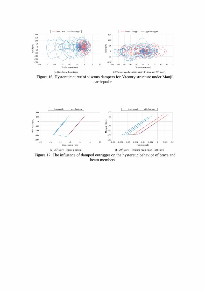
5.5 Hysteretic behavior of damper and steel members
The force–displacement hysteretic curve of damper element for 30-story structure
subjected to Manjil earthquake can be seen in Figure 16. The results are for systems
with one damped outrigger at two positions and the case of two damped outriggers
located at 13th
story and 23th
story. It is observed that viscous damper in the case of
outrigger placed at mid-height dissipates more seismic energy which implies that the
damper is working efficiently. For the case of two damped outriggers, the energy
dissipated by lower and upper outrigger is also depicted in Figure 16. As seen, both
dampers have almost the same hysteretic performances.

Figure 16. [Near Here]
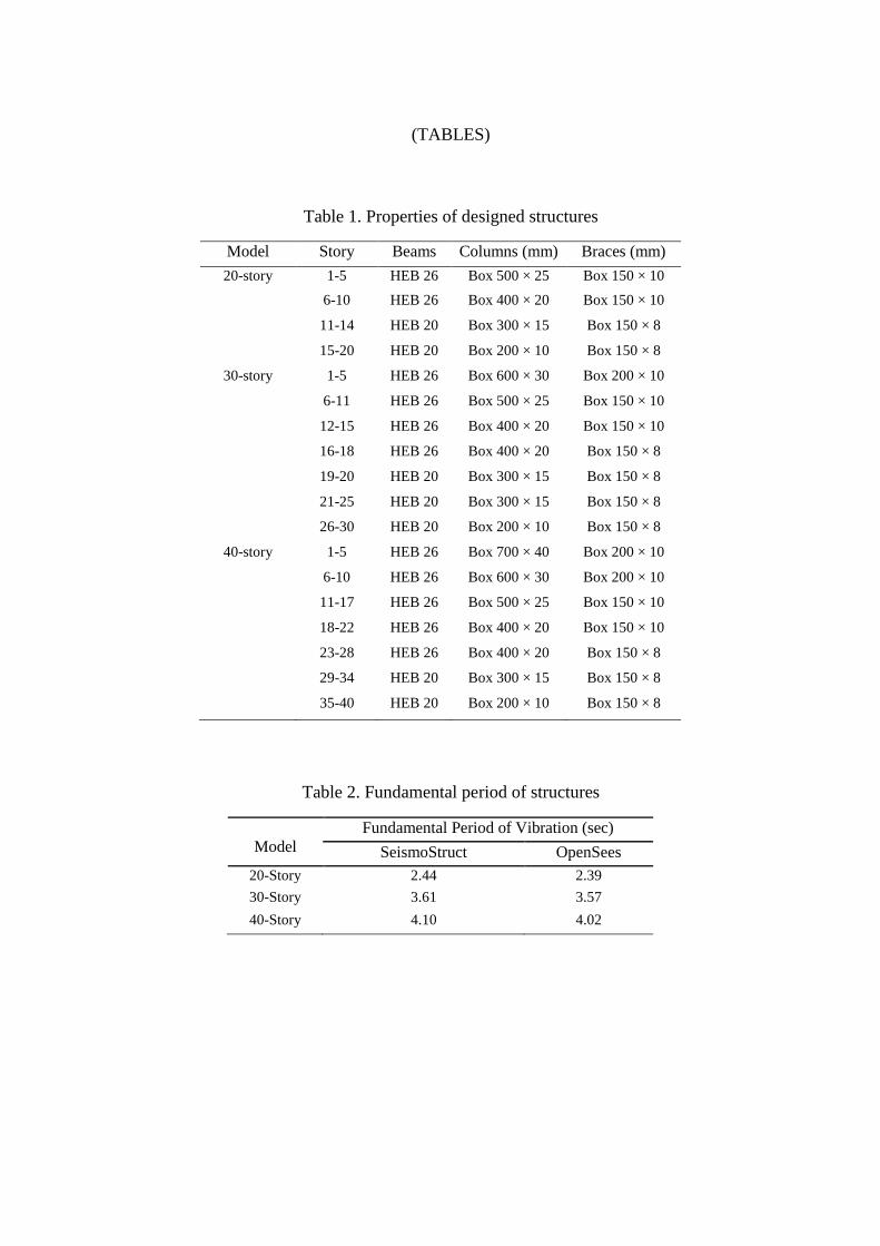
Furthermore, the damped outrigger system can significantly mitigate seismic demand
and damage to the main structural components. Figure 17 shows the effect of damped
outrigger on the hysteretic behavior of 25th
story brace and 29th
story exterior beam. The
results corresponding to 30-story structure with one damped outrigger at mid-height
subjected to Manjil ground motion are plotted in comparison with the intact model. It
can be observed that, under optimal outrigger arrangement, the addition of viscous
dampers decreases both the seismic displacement demand of exterior beam and core
brace element, leading to increase of the seismic performance level of the damped
outrigger systems with respect to the intact model.
Figure 17. [Near Here]
6. Conclusions
This paper has investigated the influence of damped outriggers arrangement on the base
shear force and the inter-story drift ratio of high-rise structures. For this purpose, three
models involving 20-story, 30-story and 40-story are presented. Preliminary design of
these models was performed by linear response spectrum analysis to satisfy the
requirements of Iranian National Buildings Codes. The deficiency observed in the initial
design procedure decreased by adding damped outriggers to the structures. Eight ground
motions are applied to obtain the nonlinear seismic response of tall buildings. The main
conclusions of this study can be summarized as follows:
1. The optimum location of damped outriggers for minimizing base shear force
under seismic excitation is mainly the same as that obtained for conventional
outriggers statically loaded.
2. Placing the outrigger at the highest level has a significant influence on the control
of lateral deflections.
3. The efficiency of viscous dampers in the case of damped outrigger at the mid-
height is better than the case of damped outrigger at base level.
4. The optimum number of damped outriggers depends on the height of structure.
Accordingly, the number of required outriggers increase with the building height.
5. Damping coefficient of the outriggers affects the seismic response of the
structures. Consequently, it must be adjusted to an appropriate value.
REFERENCES
[1] Stafford Smith, B. and Coull, A. "Tall Building Structures: Analysis and
Design", John Wiley & Sons, New York (1991).
[2] Choi, H., Ho, G., Joseph, L. and Mathias, N. "Outrigger Design for High-Rise
Buildings: An output of the CTBUH Outrigger Working Group", Council on Tall
Buildings and Urban Habitat, Chicago (2012).
[3] Applied Technology Council. "Modeling and acceptance criteria for seismic
design and analysis of tall buildings", PEER/ATC-72-1, Prepared for Pacific
Earthquake Engineering Research Center (PEER), California (2010).
[4] Smith, R.J. and Willford, M.R. "Damped outriggers for tall buildings", The
ARUP Journal, 3, pp. 15-21 (2008).
[5] Taranath, B.S. "Optimum belt truss locations for high-rise structures", AISC
Engineering Journal, 11(1), pp. 18-21 (1974).
[6] McNabb, J.W. and Muvdi, B.B. "Drift reduction factors for belted high-rise
structures", Engineering Journal, 3nd Quarter, pp. 88-91 (1975).
[7] Rutenberg, A. and Tal, D. "Lateral load response of belted tall building
structures", Engineering Structures, 9(1), pp. 53-67 (1987).
[8] Stafford Smith, B. and Salim, I. "Parameter study of outrigger-braced tall
building structures", Journal of the Structural Division, 107(10), pp. 2001-2014
(1981).
[9] Wu, J.R. and Li, Q.S. "Structural performance of multi-outrigger-braced tall
buildings", The Structural Design of Tall and Special Buildings, 12(2), pp. 155-
176 (2003).
[10] Smith, R.J. and Willford, M.R. "The damped outrigger concept for tall
buildings", The Structural Design of Tall and Special Buildings, 16(4), pp. 501-
517 (2007).
[11] Zhou, Y. and Li, H. "Analysis of a high-rise steel structure with viscous damped
outriggers", The Structural Design of Tall and Special Buildings, 23(13), pp.
963-979 (2014).
[12] Deng, K., Pan, P., Lam, A. and Xue, Y. "A simplified model for analysis of
high-rise buildings equipped with hysteresis damped outriggers", The Structural
Design of Tall and Special Buildings, 23(15), pp. 1158-1170 (2014).
[13] Chen, Y., McFarland, D.M., Wang, Z., Spencer Jr, B.F. and Bergman, L.A.
"Analysis of tall buildings with damped outriggers", Journal of Structural
Engineering, 115(4), pp. 1435-1443 (2013).
[14] Tan, P., Fang, C. and Zhou, F. "Dynamic characteristics of a novel damped
outrigger system", Earthquake Engineering and Engineering Vibration, 13(2),
pp. 293-304 (2014).
[15] Fang, C.J., Tan, P., Chang, C.M. and Zhou, F.L. "A general solution for
performance evaluation of a tall building with multiple damped and undamped
outriggers", The Structural Design of Tall and Special Buildings, 24(12), pp.
797-820 (2015).
[16] Huang, B. and Takeuchi, T. "Dynamic response evaluation of damped-outrigger
systems with various heights.", Earthquake Spectra, 33(2), pp. 665-685 (2017).
[17] Morales-Beltran, M., Turan, G,, Yildirim, U., Paul, J. "Distribution of strong
earthquake input energy in tall buildings equipped with damped outriggers.",
The Structural Design of Tall and Special Buildings, Early View (2018).
[18] Youssef, N., Wilkerson, R., Fischer, K. and Tunick, D. " Seismic performance
of a 55-storey steel plate shear wall", The Structural Design of Tall and Special
Buildings, 19(1-2), pp. 139-165 (2010).
[19] Beiraghi, H., Kheyroddin, A. and Kafi, M.A. "Effect of record scaling on the
behavior of reinforced concrete core-wall buildings subjected to near-fault and
far-fault earthquakes", Scientia Iranica A, 24(3), pp. 884-899 (2017).
[20] Beiraghi, H. and Siahpolo, N. "Seismic assessment of RC core-wall building
capable of three plastic hinges with outrigger.", The Structural Design of Tall
and Special Buildings, 26(2): e1306 (2017).

[21] Beiraghi, H. "Forward directivity near-fault and far-fault ground motion effects
on the responses of tall reinforced concrete walls with buckling-restrained brace
outriggers", Scientia Iranica A, (in press).
[22] American Institute of Steel Construction. "specification for structural steel
buildings", ANSI/AISC 360-10, Chicago, IL (2010).
[23] American Institute of Steel Construction. "Seismic provisions for structural steel
buildings", ANSI/AISC 341-10, Chicago, IL (2010).
[24] American Society of Civil Engineers. "Minimum design loads for buildings and
other structures", ASCE/SEI 7-10, New York (2010).
[25] OpenSees (Open System for Earthquake Engineering Simulation platform),
Version 2.4.0, developed by the Pacific Earthquake Engineering Research
Center (PEER), Berkeley, http://opensees.berkeley.edu/
[26] Uriz, P. and Mahin, S.A. "Toward Earthquake-Resistant Design of
Concentrically Braced Steel-Frame Structures", Report No. 2008/08, Pacific
Earthquake Engineering Research Center (PEER), College of Engineering,
University of California, Berkeley (2008).
[27] SeismoSoft. SeismoStruct: A computer program for static and dynamic
nonlinear analysis of framed structures (online), available from URL:
http://seismosoft.com/
[28] Federal Emergency Management Agency (FEMA). "Improvement of nonlinear
static seismic analysis procedures", FEMA-440, Washington, D.C. (2005).
[29] Federal Emergency Management Agency (FEMA). "Quantification of building
seismic performance factors", FEMA P695, Washington, D.C. (2009).
[30] Pacific Earthquake Engineering Research Center (PEER). “PEER Strong Motion
Database”, http://peer.berkeley.edu/smcat/.

Figure Captions
Figure 1. Schematic plot of studied structures
Figure 2. Inter-story drift values of structures under preliminary design
Figure 3. Proposed damping ratio for tall buildings [3,4]
Figure 4. Acceleration response spectrum of the scaled ground motion records
Figure 5. Schematic plots of damped outrigger system configuration
Figure 6. The effect of damping coefficient on base shear force for 20-story and 30-
story structures subjected to Hector Mine earthquake
Figure 7. Studied positions of damped outriggers for 40-story frame
Figure 8. Effect of one damped outrigger location on the maximum base shear force
(a) 20-story frame, (b) 30-story frame, (c) 40-story frame
Figure 9. Effect of two damped outriggers locations on the maximum base shear
force (a) 20-story frame, (b) 30-story frame, (c) 40-story frame
Figure 10. Effect of three damped outriggers locations on the maximum base shear
force (a) 20-story frame, (b) 30-story frame, (c) 40-story frame
Figure 11. Effect of one damped outrigger location on the inter-story drift ratio
(a) 20-story frame, (b) 30-story frame, (c) 40-story frame
Figure 12. Effect of two damped outriggers locations on the inter-story drift ratio
(a) 20-story frame, (b) 30-story frame, (c) 40-story frame
Figure 13. Effect of three damped outriggers locations on the inter-story drift ratio
(a) 20-story frame, (b) 30-story frame, (c) 40-story frame
Figure 14. Optimum number of damped outriggers according to base shear force
(a) 20-story frame, (b) 30-story frame, (c) 40-story frame
Figure 15. Optimum number of damped outriggers according to inter-story drift ratio
(a) 20-story frame, (b) 30-story frame, (c) 40-story frame
Figure 16. Hysteretic curve of viscous dampers for 30-story structure under Manjil
earthquake
Figure 17. The influence of damped outrigger on the hysteretic behavior of brace and
beam members

Table Captions
Table 1. Properties of designed structures
Table 2. Fundamental period of structures
Table 3. Properties of ground motion records
Table 4. Characteristics of damped outrigger components

(FIGURES)
Figure 1. Schematic plot of studied structures
Figure 2. Inter-story drift values of structures under preliminary design

Figure 3. Proposed damping ratio for tall buildings [3, 4]
Figure 4. Acceleration response spectrum of the scaled ground motion records

Figure 5. Schematic plots of damped outrigger system configuration
3000
3250
3500
3750
4000
0 10 20 30 40 50
Bas
e S
hear
(kN
)
Daming Coefficient (MN.sec/m)
Base level Mid‐height
(b) 30-story structure
1500
1750
2000
2250
2500
0 10 20 30 40 50
Bas
e S
hear
(kN
)
Daming Coefficient (MN.sec/m)
Base level Mid-height
(a) 20-story structure Figure 6. The effect of damping coefficient on base shear force for 20-story and 30-
story structures subjected to Hector Mine earthquake
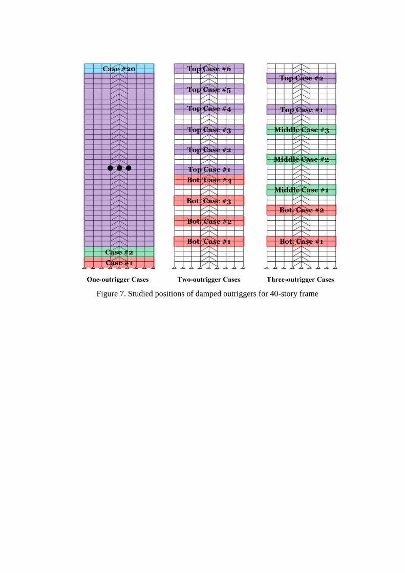
Figure 7. Studied positions of damped outriggers for 40-story frame

Figure 8. Effect of one damped outrigger location on the maximum base shear force
(a) 20-story frame, (b) 30-story frame, (c) 40-story frame
Figure 9. Effect of two damped outriggers locations on the maximum base shear
force (a) 20-story frame, (b) 30-story frame, (c) 40-story frame

Figure 10. Effect of three damped outriggers locations on the maximum base shear
force (a) 20-story frame, (b) 30-story frame, (c) 40-story frame

Figure 11. Effect of one damped outrigger location on the inter-story drift ratio
(a) 20-story frame, (b) 30-story frame, (c) 40-story frame

Figure 12. Effect of two damped outriggers locations on the inter-story drift ratio
(a) 20-story frame, (b) 30-story frame, (c) 40-story frame

Figure 13. Effect of three damped outriggers locations on the inter-story drift ratio
(a) 20-story frame, (b) 30-story frame, (c) 40-story frame
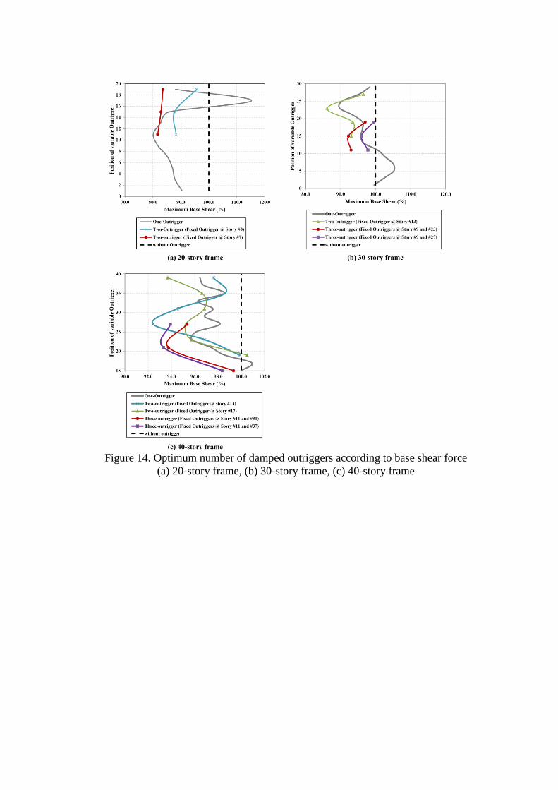
Figure 14. Optimum number of damped outriggers according to base shear force
(a) 20-story frame, (b) 30-story frame, (c) 40-story frame

Figure 15. Optimum number of damped outriggers according to inter-story drift ratio
(a) 20-story frame, (b) 30-story frame, (c) 40-story frame
-250
-200
-150
-100
-50
0
50
100
150
200
-30 -25 -20 -15 -10 -5 0 5 10
Forc
e (k
N)
Displacement (mm)
Base Level Mid-height
(a) One damped outrigger
-100
-50
0
50
100
150
-30 -25 -20 -15 -10 -5 0 5 10 15 20
Forc
e (k
N)
Displacement (mm)
Lower Outrigger Upper Outrigger
(b) Two damped outriggers (at 13th
story and 23th
story) Figure 16. Hysteretic curve of viscous dampers for 30-story structure under Manjil
earthquake
-1200
-900
-600
-300
0
300
600
-20 -15 -10 -5 0 5 10
Axi
al F
orc
e (k
N)
Displacement (mm)
Intact model with Outrigger
(a) 25th story –�Brace element
-200
-150
-100
-50
0
50
100
-0.03 -0.025 -0.02 -0.015 -0.01 -0.005 0 0.005 0.01
Mo
men
t (k
N.m
)
Rotation (rad)
Intact model with Outrigger
(b) 29th story –�Exterior beam span (Left side)
Figure 17. The influence of damped outrigger on the hysteretic behavior of brace and
beam members
(TABLES)
Table 1. Properties of designed structures
Model Story Beams Columns (mm) Braces (mm)
20-story 1-5 HEB 26 Box 500 × 25 Box 150 × 10
6-10 HEB 26 Box 400 × 20 Box 150 × 10
11-14 HEB 20 Box 300 × 15 Box 150 × 8
15-20 HEB 20 Box 200 × 10 Box 150 × 8
30-story 1-5 HEB 26 Box 600 × 30 Box 200 × 10
6-11 HEB 26 Box 500 × 25 Box 150 × 10
12-15 HEB 26 Box 400 × 20 Box 150 × 10
16-18 HEB 26 Box 400 × 20 Box 150 × 8
19-20 HEB 20 Box 300 × 15 Box 150 × 8
21-25 HEB 20 Box 300 × 15 Box 150 × 8
26-30 HEB 20 Box 200 × 10 Box 150 × 8
40-story 1-5 HEB 26 Box 700 × 40 Box 200 × 10
6-10 HEB 26 Box 600 × 30 Box 200 × 10
11-17 HEB 26 Box 500 × 25 Box 150 × 10
18-22 HEB 26 Box 400 × 20 Box 150 × 10
23-28 HEB 26 Box 400 × 20 Box 150 × 8
29-34 HEB 20 Box 300 × 15 Box 150 × 8
35-40 HEB 20 Box 200 × 10 Box 150 × 8
Table 2. Fundamental period of structures
Model
Fundamental Period of Vibration (sec)
SeismoStruct OpenSees
20-Story 2.44 2.39
30-Story 3.61 3.57
40-Story 4.10 4.02

Table 3. Selected ground motions' characteristics
Earthquake
Name
Date
Ms
Station
Name Epicenter
(km)
Component (deg)
PGA (g)
Scaled PGA (g)
Hector Mine 1999 7.1 Hector 26.5 90 0.34 0.49
Kobe 1995 6.9 Nishi-Akashi 8.7 0 0.51 0.53
Manjil 1990 7.4 Abbar 40.4 TR 0.50 0.50
Loma Prieta 1989 7.1 Saratoga 27.2 0 0.51 0.54
Loma Prieta 1989 7.1 Gilory 29.0 67 0.36 0.55
Northridge 1994 6.8 Castaic 40.7 360 0.51 0.51
Morgan Hill 1984 6.1 Gilory #6 36.3 90 0.29 0.50
Tabas 1978 6.9 Dayhook 20.6 TR 0.41 0.55
Table 4. Characteristics of damped outrigger components
Model
No. of outriggers
Viscous damper
Bracing (mm) Stiffness (kN/m)
Damping Coefficient (kN.sec/m)
20-Story 1 50000 2000 Box 150 × 10
2 50000 1000 Box 150 × 10
30-Story 1 50000 2500 Box 200 × 10
2, 3 50000 1000 Box 200 × 10
40-Story 1 50000 3500 Box 200 × 10
2, 3 50000 1500 Box 200 × 10
AUTHORS’ BIOGRAPHIES
Hamid Asadi Ghoozhdi is a PhD Candidate from University of Tehran. He received
his MSc degrees in Structural Engineering from the Sharif University of Technology
and B.Sc. degree in civil engineering from Ferdowsi University of Mashhad. His
research interests lie in the field of performance based seismic design of tall buildings,
soil-structure interaction problems and seismic bridge design.
Masood Mofid is a professor of Civil Engineering Department at Sharif University of
Technology. He earned his BSc degree from the University of Tehran. Moreover, he
received his MSc and PhD degrees from Rice University. His research applies the
principles of structural dynamics and engineering mechanics.