EFFECT OF CONFINING METHOD ON THE DUCTILITY · PDF fileJournal of Engineering Sciences, Assiut...
17
Journal of Engineering Sciences, Assiut University, Vol. 35, No. 3 pp. 617-633, May 2007 617 EFFECT OF CONFINING METHOD ON THE DUCTILITY OF OVER-REINFORCED CONCRETE BEAMS M. M. Ahmed, O. A. Farghal, Ass. Prof. Dr of Civil Eng. Faculty of Eng. Assiut University, Assiut, Egypt. A. K. Nagah and Lect. Dr of Civil Eng. Faculty of Eng. Al-Azhar University, Qena, Egypt. A. A. Haridy Demonstrator in Civil Eng. Faculty of Eng. Al-Azhar University, Qena, Egypt. (Received March 29, 2007 Accepted April 16, 2007) Most design codes limit the amount of tensile reinforcement in beams to avoid the brittle failure. However, sometimes a high percentage of steel reinforcement is used in order to minimize structural depth and still provide adequate stiffness. The objective of this work is to investigate and evaluate the methods of improving the behavior of over-reinforced beams. The effect of different types of techniques on the enhancement of strength and ductility of such beams was presented. An experimental and theoretical study of the behavior of fourteen over-reinforced, either internally confined or externally plated C. beams with 240 cm length and a cross-section of 15 x 23cm were carried out. Variables such as helix pitch, helix diameter, concrete compressive strength, longitudinal reinforcement ratio and confining with steel plate were considered. The results were discussed, analyzed and compared with those obtained theoretically. The results indicated the contribution of proposed techniques to the structural ductility for improving behaviour of such over-reinforced concrete beams. Finally some valuable conclusions and recommendations were given. KEYWORDS: over-reinforced, confining, helically reinforced, ductility, plated beams. INTRODUCTION The brittleness of reinforced concrete members increases with the use of high percentages of longitudinal reinforcement. Over-reinforced sections fail suddenly by crushing of the compression concrete when their ultimate compressive strain has been exceeded, while the strain in the longitudinal reinforcement has not reached yield. The limited extent of the deflection and cracking found in over-reinforced beams gives insufficient warning of impending failure. At present, in order to avoid brittle compression failures, codes of practice sensibly prohibit the use of over-reinforced sections [1]. Previous researches had shown that the ductility and flexural response of over- reinforced and prestressed concrete beams can be enhanced by the use of full-depth
Transcript of EFFECT OF CONFINING METHOD ON THE DUCTILITY · PDF fileJournal of Engineering Sciences, Assiut...

Journal of Engineering Sciences, Assiut University, Vol. 35, No. 3 pp. 617-633, May 2007
617
EFFECT OF CONFINING METHOD ON THE DUCTILITY OF OVER-REINFORCED CONCRETE BEAMS
M. M. Ahmed, O. A. Farghal, Ass. Prof. Dr of Civil Eng. Faculty of Eng. Assiut University, Assiut, Egypt.
A. K. Nagah and Lect. Dr of Civil Eng. Faculty of Eng. Al-Azhar University, Qena, Egypt.
A. A. Haridy
Demonstrator in Civil Eng. Faculty of Eng. Al-Azhar University, Qena, Egypt.
(Received March 29, 2007 Accepted April 16, 2007)
Most design codes limit the amount of tensile reinforcement in beams to avoid the brittle failure. However, sometimes a high percentage of steel reinforcement is used in order to minimize structural depth and still provide adequate stiffness. The objective of this work is to investigate and evaluate the methods of improving the behavior of over-reinforced beams. The effect of different types of techniques on the enhancement of strength and ductility of such beams was presented. An experimental and theoretical study of the behavior of fourteen over-reinforced, either internally confined or externally plated C. beams with 240 cm length and a cross-section of 15 x 23cm were carried out. Variables such as helix pitch, helix diameter, concrete compressive strength, longitudinal reinforcement ratio and confining with steel plate were considered. The results were discussed, analyzed and compared with those obtained theoretically. The results indicated the contribution of proposed techniques to the structural ductility for improving behaviour of such over-reinforced concrete beams. Finally some valuable conclusions and recommendations were given. KEYWORDS: over-reinforced, confining, helically reinforced, ductility, plated beams.
INTRODUCTION The brittleness of reinforced concrete members increases with the use of high percentages of longitudinal reinforcement. Over-reinforced sections fail suddenly by crushing of the compression concrete when their ultimate compressive strain has been exceeded, while the strain in the longitudinal reinforcement has not reached yield. The limited extent of the deflection and cracking found in over-reinforced beams gives insufficient warning of impending failure. At present, in order to avoid brittle compression failures, codes of practice sensibly prohibit the use of over-reinforced sections [1].
Previous researches had shown that the ductility and flexural response of over-reinforced and prestressed concrete beams can be enhanced by the use of full-depth

M. M. Ahmed, O. A. Farghal, A. K. Nagah and A. A. Haridy 618
rectangular steel wire helical reinforcement [2,3]. However, circular helical reinforcement, located entirely above the longitudinal reinforcement and enveloping the entire compression zone, provides greater confinement [4,5].
Whitehead and Ibell [6] concluded that, by placing a steel helix of 3 or 4.8mm wire diameter in the compression zone of heavily over-reinforced concrete beam considerable ductility has been achieved, even when using a longitudinal steel percentage of about 7%. Providing a longitudinal compression reinforcement or using randomly oriented steel fibers or by installing rectangular stirrups in the compression zone which restrains the lateral expansion enhance the strength and ductility of over-reinforced beams. [5, 6, 7, 8, 9, 10, 11, 12]
However most of the previous works have dealt mainly with the internal confinement in the compression zone of these members, especially those of high strength concrete. Few available researches have studied the effect of internal confinement with long and short stirrups together or the external confinement in case of the existing members such as glueded and bolted steel plates to the top surface of the beams.
This paper presents an experimental study to investigate the contribution of some proposed techniques for improving behavior of such over-reinforced concrete beams. The test program includes two main parts: The first one is that related to some precautions provided internally during casting the beams by means of providing either steel helix or short rectangular stirrups. The second one deals with that provided to the external surface of the beams by gluing and bolting steel plates to the top surface of the beams.
EXPERIMENTAL PROGRAM
Details of the tested beams
Fourteen rectangular beams were tested in this work. All the tested beams have the same concrete dimensions. Beams of series A, B and C were reinforced with six bottom bars of 16 mm in diameter (As), two top bars of 10 mm in diameter and steel helix of 13 cm helical diameter with different values of wire diameter and pitch placed in concrete compression zone. Beams of series D and E provided with short rectangular stirrups instead of steel helix. Beams of series G provided with upper steel plates. Tables (1) as well as Fig (1) show the details of the main parameters considered in this investigation.
Materials
All beams were made using normal concrete having small range of variable concrete compressive strength, see table (1). The used concrete was made from Ordinary Portland Cement, local sand which has specific weight, bulk density and fineness modulus of 2.5, 1700 kg/m3 and 2.43 respectively and Gravel of 20 mm maximum nominal size. The water cement ratio w/c was 0.55 for all batches. The high tensile steel with about 4370 kg/cm2 proof stress, was used as main reinforcement, while the

EFFECT OF CONFINING METHOD ON THE DUCTILITY…. 619
steel used as stirrups was mild steel of about 3222 kg/cm2 yield strength, and for helical steel fy was 3890, 6360 and 5090 kg/cm2 for Φ6, Φ4 and Φ3 respectively.
Preparation of test specimens and Test procedure
The concrete was batched in the laboratory using a pan mixer. Control specimens including cubes of 15 cm side length were cast from each batch. The concrete was placed by hand in steel forms and compacted using a 2.5 cm diameter electric vibrator. The tested beams and the corresponding control specimens were tested in the same day after 28 days from casting. All the beams were simply supported and the load was applied to the beams through two points as shown in Fig (1). The loading was applied in increments of 0.5 ton. The crack pattern, cracking load, mid-span deflection, failure load and strains in longitudinal steel at mid-span were measured and recorded.
Table (1): Details of tested beams
Series Beam No.
fcu Kg/cm2
ф mm
S (cm)
ρ (%)
ρmax (%)
Area of plates Ap (cm2)
Type of technique
A Bsp1 330 6 4 4.23 1.42 -
Steel helix
Bsp3 265 6 4 4.23 1.14 - Bsp2 225 6 4 4.23 0.97 -
B Bsp4 295 4 4 4.23 1.27 - Bsp5 265 3 4 4.23 1.14 -
C Bsp6 215 3 3 4.23 0.93 - Bsp7 215 3 2 4.23 0.93 -
D Bst1 265 - 10 2.82 1.14 -
Short stirrups Bst2 220 - 10 4.23 0.95 - Bst3 265 - 10 5.64 1.14 -
E Bst4 265 - - 4.23 1.14 - - Bst5 265 - 5 4.23 1.14 - Short stirrups
G Bst6 265 - - 2.82 1.14 12x0.6
steel plates Bst7 265 - 10 2.82 1.14 12x0.3
S : pitch of the spiral or spacing between short stirrups. ф : diameter of helical reinforcement.
TEST RESULTS AND DISCUSSION
Ductility
The displacement ductility index [µD] can be measured as the ratio between maximum deflection [∆max] (corresponding to 90% of the maximum recorded load capacity) and the deflection corresponding to cracking load [∆cr]. The ductility index ratio [R] is the ductility index of the different tested beams compared with the corresponding

M. M. Ahmed, O. A. Farghal, A. K. Nagah and A. A. Haridy 620
reference beam Bst4, table (2). It emerged that, both confined and plated beams showed an acceptable increased ductility in comparison with that of the corresponding reference beam Bst4, particularly in case of beams having higher concrete compressive strength and that having biggest wire diameter of spiral (Bsp1, Bsp4 and Bsp3).
a) Reinforcement details for beams of series A, B and C
b) Reinforcement details for beams of series D and E
c) Reinforcement details for beams of series G
Fig (1): Details of the tested beams
15
2 8
4 16
10 8/m\
P/2 P/2
85 cm 85 cm 50 cm 10 10
170 cm
23
20
12
15
23
20 13
6 16
10 8/m\
2 10 P/2 P/2
85 cm 85 cm 50 cm 10 10
Spacing of sh. st.
15
23
20
6 16
10 8/m\
2 10 P/2 P/2
85 cm 85 cm 50 cm 10 10
Pitch (Sh) Rh=13
EFFECT OF CONFINING METHOD ON THE DUCTILITY…. 621
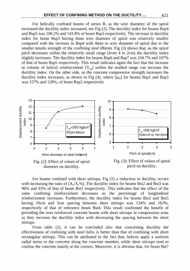
For helically confined beams of series B, as the wire diameter of the spiral increased the ductility index increased, see Fig (2). The ductility index for beams Bsp4 and Bsp5 was 108.2% and 141.8% of beam Bsp3 respectively. The increase in ductility index for beam Bsp3 having 6mm wire diameter of spiral was relatively smaller compared with the increase in Bsp4 with 4mm in wire diameter of spiral due to the smaller tensile strength of the confining steel Ø6mm. Fig (3) shows that, as the spiral pitch decreases within the relatively small range (from 4 to 2cm) the ductility index slightly increases. The ductility index for beams Bsp6 and Bsp7 was 104.7% and 107% of that of beam Bsp5 respectively. This result indicates again the fact that the increase in volume of helical reinforcement [Vsp] within the studied range can increase the ductility index. On the other side, as the concrete compressive strength increases the ductility index increases, as shown in Fig (4), where [µD] for beams Bsp1 and Bsp3 was 157% and 128%, of beam Bsp2 respectively
For beams confined with short stirrups, Fig (5) a reduction in ductility occurs
with increasing the ratio of (As/Ac%). The ductility index for beams Bst2 and Bst3 was 96% and 93% of that of beam Bst1 respectively. This indicates that the effect of the same confining reinforcement decreases as the percentage of longitudinal reinforcement increases. Furthermore, the ductility index for beams Bst2 and Bst5 having 10cm and 5cm spacing between short stirrups was 134% and 163%, respectively of that of reference beam Bst4. This result confirmed the benefit of providing the over reinforced concrete beams with short stirrups in compression zone as they increase the ductility index with decreasing the spacing between the short stirrups.
From table (2), it can be concluded also that concerning ductility the effectiveness of confining with steel helix is better than that of confining with short rectangular stirrups. This can be attributed to the fact that, helices apply a uniform radial stress to the concrete along the concrete member, while short stirrups tend to confine the concrete mainly at the corners. Moreover, it is obvious that, for beam Bst7
Fig. (3): Effect of values of spiral pitch on ductility.
f cu=265 kg/cm2
Diam. of st. he=3mm
5
6
7
8
9
10
1 2 3 4 5
Pitch of spiral (cm)
Dis
plac
emen
t duc
tility
in
dex
Fig. (2): Effect of values of spiral diameter on ductility.
f cu=265 kg/cm2
Pich=40cm
6
7
8
9
10
11
12
13
2 3 4 5 6 7
Wire diameter of steel helix (mm)
Dis
plac
emen
t duc
tility
in
dex

M. M. Ahmed, O. A. Farghal, A. K. Nagah and A. A. Haridy 622
provided with steel plates, the ductility index was 116% of that of reference beams Bst1. The technique of providing steel plates on the top compression side seems to have a significant effect on the ductility index, provided that, the plates must be good fastened to the upper side. Furthermore, the ductility index for beam Bst6 in which the short stirrups were replaced by additional another steel plate was 105% of that of beam Bst7 having short stirrups. From the previous result, it is emerged that using additional steel plate instead of short rectangular stirrups gave a slightly better ductility index.
Load Deflection Diagrams.
The results shows that confining the concrete in compression zone with steel helix or short stirrups or glued steel plates on to top face of over reinforced beams improve their ductility. The flat Plato of the curves for these beams showed a considerable increase. The maximum deflection decreases slightly as the concrete compressive strength increases. The maximum deflection for beams Bsp3 and Bsp1 was 90.3% and 120% of that of beam Bsp2 respectively, see Fig (6). On the other hand, the ultimate mid-span deflection decreases as the volume of helical reinforcement decreases, as shown in Fig (8). The deflection for beam Bsp6 at loads greater than 0.8Pu is bigger than the corresponding value of the reference beam Bst4. This can be attributed to the fact that the effect of confining is more activated at higher load levels.
The maximum deflection for beams Bst7 provided with steel plates was 195% of that of reference beams Bst1 without steel plates. Furthermore the maximum deflection for beam Bst6 having steel plate with cross section Ap=720 mm2 and without short rectangular stirrups was more than that of beam Bst7 having Ap=360 mm2 and with short rectangular stirrups, see table (2). This result confirmed again that replacing the short rectangular stirrups with steel plates gives a better ductility.
S=10cmf cu=265kg/cm2
5.5
6
6.5
7
7.5
8
2 3 4 5 6
(As/Ac) %
Dis
plac
emen
t du
ctili
ty in
dex
Fig. (5): Effect of (ρ%) ratio on ductility
Fig. (4): Effect of (fcu) on ductility.
Diam. of st. h=6mmPitch=40mm
7
8
9
10
11
12
13
14
15
200 250 300 350
Concrete compressive strength kg/cm2
Dis
plac
emen
t du
ctili
ty in
dex

EFFECT OF CONFINING METHOD ON THE DUCTILITY…. 623
0
5
10
15
20
0 1 2 3 4 5
Mid-span deflection (cm)
Load
ton
Beam Bsp 5 (pitch of st . h=40mm)Beam Bsp 6 (pitch of st . h=30mm)Beam Bsp 7 (pitch of st . h=20mm)Beam Bst 4 (-)
Fig. (8): Deflection curves for beams with different values of spiral pitch.
0
5
10
15
20
0 1 2 3 4 5
Mid-span deflection (cm)
Load
ton
Beam Bst 2 (S=10 cm)
Beam Bst 4 (-)
Beam Bst 5 (S=5 cm)
Fig. (9): Deflection curves for beams with different values of (ρ%).
0
5
10
15
20
0 1 2 3 4 5
Mid-span deflection (cm)
Load
ton
Beam Bsp 1 (fcu = 330 kg\cm2)
Beam Bsp 2 (fcu = 225 kg\cm2)Beam Bsp 3 (fcu = 265 kg\cm2)
Beam Bst 4 (ref .)
Fig. (6): Deflection curves for beams with different values of fcu.
0
5
10
15
20
0 1 2 3 4 5
Mid-span deflection (cm)
Load
ton
Beam Bsp 3 (Diam. of st . h=6mm)Beam Bsp 4 (Diam. of st . h=4mm)Beam Bsp 5 (Diam. of st . h=3mm)Beam Bst 4 (-)
Fig. (7): Deflection curves for beams with different wire diameter.
0
5
10
15
20
0 1 2 3 4 5
Mid-span deflection (cm)
Load
ton
Beam Bst1 (p=2.82%)Beam Bst2 (p=4.23%)Beam Bst3 (p=5.64%)Beam Bst4 (ref )
Fig. (10): Deflection curves for beams with different short stirrups space.
Fig. (11): Deflection curves for beams with different values of (Ap).
0
5
10
15
20
0 1 2 3 4 5 6
Mid-span deflection (cm)
Load
ton
Beam Bst1 (short stir)
Beam Bst4 (-)
Beam Bst6 (Asp=720mm2)
Beam Bst7 (Asp=360mm2)

M. M. Ahmed, O. A. Farghal, A. K. Nagah and A. A. Haridy 624
Crack Patterns and Modes of Failure
The initiation and propagation of cracks for the different tested beams Fig (12), was obtained visually with a magnifying glass. The cracks were first initiated at the bottom fibers in the constant moment zone for all confined and plated beams. As the load increased, new cracks were created along the beam and the formed cracks propagated towards the points of load application. The rate of cracks propagation was smaller than that of the reference beam Bst4. Prior to failure a horizontal crack was initiated near the upper side of the beam at the steel level and the concrete cover began to spell off. At failure the height of the cracked portion of the tested beams was some what more than that of the reference beam Bst4, particularly in case of beam Bst6 provided with steel plates on to the top compression fiber. The mode of failure for the different tested beams is also included in Table (2). The reference beam Bst4 (without any confining reinforcement) failed in a brittle flexural compression by sudden concrete crushing in the compression zone and the spalling off concrete cover occurred just prior to crushing of concrete. For the confined beams, the modes of failure were also flexural compression, however they changed from a brittle to a relatively ductile one in a gradual manner through crushing in the compression zone and buckling in upper steel was observed. The spalling off concrete cover began earlier than in the corresponding reference beam Bst4. The obtained results showed a similar trend as was observed in a previous work by Whitehead and Ibell [6]. The plated beams Bst6 and Bst7 failed in flexural compression in a ductile way by gradual crushing of the compression zone and local buckling of the fixed steel plate. The horizontal upper cracks were observed at about 95% of its ultimate load, and then the local buckling of steel plat occurred at the instant of failure.
Cracking and Ultimate Loads
The cracking load was not influenced considerably with the presence of steel helix or steel plate. This can be attributed to the fact that the first crack was a flexural one and had occurred at relatively low load before confining effect took place.
From table (2), it can be seen that there was a gain in load capacity for all beams especially in case of beams Bsp1, Bst3, Bst5 and Bst6. The increase in concrete compressive strength or longitudinal reinforcement ratio or glued steel plate showed a considerable increase on the ultimate load as shown in Figs (13) and (15). The ultimate load of beams in series D having fcu = 330, 225 and 265 kg\cm2 was 1.33, 1.17 and 1.18 times that of the corresponding reference beam Bst4 respectively. The obtained results confirm the previous results reported by Whitehead and Ibell [6]. However the spiral pitch, diameter of spiral wire, and spacing of short stirrups, within the studied range have not affected considerably Pu, see Fig (14). Beams Bst2 and Bst5 having spacing of short rectangular stirrups equal to 10 and 5 cm, the ultimate loads, were 1.11 and 1.27 times that of the reference beam Bst4 respectively.

EFFECT OF CONFINING METHOD ON THE DUCTILITY…. 625
Fig (12):Pattern of cracks and modes of failure for tested beams.

M. M. Ahmed, O. A. Farghal, A. K. Nagah and A. A. Haridy 626
Table (2): Results of tested beams
Beam No.
Pcr ton
Pu ton
Pu/Pcr Psp/Pu Ductility
Mode of failure ∆cr (cm)
∆max (cm)
µD R %
Bsp1 2.5 17.4 6.96 0.86 0.14 2.1 14.8 276 Flex. Comp. (ductile) Bsp3 2.5 15.5 6.2 0.9 0.13 1.58 12.0 225 Flex. Comp. (ductile) Bsp2 3 15.4 5.13 0.93 0.18 1.75 9.4 176 Flex. Comp. (ductile) Bsp4 2.5 14.7 5.88 0.88 0.15 1.74 11.1 208 Flex. Comp. (ductile) Bsp5 3 15.1 5.05 0.92 0.2 1.7 8.5 159 Flex. Comp. (ductile) Bsp6 2.5 15.3 6.14 0.91 0.12 1.14 8.9 166 Flex. Comp. (ductile) Bsp7 2.5 15.2 6.1 0.92 0.21 1.99 9.1 170 Flex. Comp. (ductile) Bst1 2.5 12.4 4.96 0.84 0.17 1.28 7.45 139 Flex. Comp. (ductile) Bst2 3 14.6 4.86 0.92 0.17 1.27 7.17 134 Flex. Comp. (ductile) Bst3 4 16.9 4.2 0.88 0.23 1.6 6.95 130 Flex. Comp. (ductile) Bst4 3.5 13.1 3.74 0.95 0.23 1.23 5.34 100 Flex. Comp. (brittle) Bst5 2.5 16.6 6.64 0.9 0.17 1.55 8.75 163 Flex. Comp. (ductile) Bst6 3 18 6 0.95 0.27 2.46 9.11 170 Flex. Comp. (ductile) Bst7 3 15.3 5.1 0.95 0.29 2.5 8.65 116 Flex. Comp. (ductile)
Pcr : the Cracking load, Psp = spalling off concrete cover load. Pu : the ultimate load, ρ = the Longitudinal reinforcement ratio. ρmax : the maximum longitudinal reinforcement ratio.
The ratio between the ultimate and the cracking loads (Pu/Pcr) for all the confined
and plated beams was bigger than that of the corresponding reference beam Bst4, which reflect also the improvement of their ductility, table (2).
Diam. of st . h=6mmPitch=40mm
02468
1012141618
200 250 300 350
Concrete compressive strength kg /cm2
Load
ton
cracking loadultimate load
Fig. (13): Effect of fcu on cracking and ultimate load.
p= 4.23%f cu = 265kg/cm2
02468
1012141618
0 5 10 15 20 25
No of short rectangular stirrups /m
Load
ton cracking load
ultimate load
Fig. (14): Effect of No. of short stirrups on cracking and ultimate load.

EFFECT OF CONFINING METHOD ON THE DUCTILITY…. 627
S=10cm
f cu=265kg/cm2
02468
1012141618
2 3 4 5 6
(As/Ac) ratio %
Load
ton cracking load
ultimate load
Fig. (15): Effect of (ρ%).on cracking and ultimate load.
PREDICTION OF THE BEHAVIOUR OF CONFINED BEAMS The tested beams with helically confined concrete were theoretically analyzed. The ultimate load and the induced deflection at mid-span for different helically confined over reinforced beams were estimated at different stages of loading; non cracked, cracked and ultimate stages. The following equations in both non linear and cracked stage with respect to Figs (16), (17), (18) and (19) are used.
])/()/2[( 2ccocccoccucc fKf εεεε −= ,
where )/)()/((05.21 2cuywhhhh ffSDRDK −+= π
fyh
= fy + (εs - εy ) Ep
)/2.0( cocccu K εε +Ψ=
)/75.0/()5.0(/tan 50 KSRKf cohhhucucc ερεθψ −+−==
Fig (17): Stress strain curve for steel
fsu
fy
εy εsu
fs
εs
Ep
Fig (16): stress-strain model for concrete confined by circular spirals. [13]
fc
kfcu
k3 fcu
0.8kfcu
0.2fcu
0.5fcu
0.2kfcu
εco A
εcco εcu
ε50u εccu
ε20u ε50uc ε20uc εc
εcco = εco k

M. M. Ahmed, O. A. Farghal, A. K. Nagah and A. A. Haridy 628
where Ep is modulus of plasticity of steel, f
yh is value of the upper yield strength, εcco is
strain of concrete at compressive cylinder strength of the unconfined concrete, fcu is the compressive strength of unconfined concrete, fcc , εc are stress and strain in concrete, ε
y is the yield or proof strain for steel, K is confinement coefficient.
Fig. (18): Section analysis for cracked stage
The Neutral axis position for the cracked nonlinear stage may be given as: 0.67bfccx
2 + (AscEsεcc + AsEsεcc )x-AsEsεccd- AscEsεccdc= 0 (4.6) The flexural strength (M) is therefore: M = Asfs(d-0.375 x) + Ascfsc (0.375x-dc ) (4.7)
Fig. (19): Section analysis for ultimate stag
The equilibrium of internal forces at ultimate gives the neutral axis position: 0.536 fcu x b +0.536 x\ b\ (fccu - fcu)+ Ascfsc - Asfs = 0 The ultimate flexural strength (Mu) is therefore: Mu = Asfs(d-0.4x) + Asc f
\y (0.4x-dc ) - 0.536 x\ b\ (fccu - fcu) (0.4x\ +dc-0.4x)
Strain distribution
εcu≥0.003
εs
εccu
d h
x
dc
εco
Beam cross section
Asc
As
b
0.67fcu
Idealized stress distribution
x 0.8x
0.67fccu
x\
0.8x\
x\
0.4x\ +dc
b\ = Rh
εc<0.003
εs
εsc
d h
x
dc
Strain distribution
εco
Asc
As
b
Beam cross section
fcc
fs
Stress distribution
Rh

EFFECT OF CONFINING METHOD ON THE DUCTILITY…. 629
A comparison between the load deflection curve obtained from experimental work and that predicted theoretically, are presented in figures (20 to 26), for beams Bsp1 to Bsp7. The figures indicated that, the deflection curves are typically similar and there is almost full agreement between the theoretical estimated up to about 50% of the ultimate load. After this limit, there is a deviation between the experimental and the theoretical curve. This deviation increased with increasing the load up to failure. The theoretical values of maximum deflection at ultimate are smaller than the experimental values except for beams Bsp1, Bsp2 and Bsp3. The experimental measured ultimate load for the tested beams was always slightly bigger than the corresponding predicted values, see Fig (20). The maximum deviation between theoretical and experimental values reaches about 18% for beam Bsp1.
0
2
4
6
8
10
12
14
16
18
20
0 0.5 1 1.5 2 2.5 3 3.5 4 4.5 5
Mid-span deflection (cm)
Load
ton
experimental
theoretical
Fig. (22): comparison of experimental and theoretical deflection of beam Bsp3
0
2
4
6
8
10
12
14
16
18
20
0 0.5 1 1.5 2 2.5 3 3.5 4 4.5 5
Mid-span deflection (cm)
Load
ton
experimental
theoretical
Fig. (23): comparison of experimental and theoretical deflection of beam Bsp4
0
2
4
6
8
10
12
14
16
18
20
0 0.5 1 1.5 2 2.5 3 3.5 4 4.5 5
Mid-span deflection (cm)
Load
ton
experimental
theoretical
Fig. (20): comparison of experimental and theoretical deflection of beam Bsp1
0
2
4
6
8
10
12
14
16
18
20
0 0.5 1 1.5 2 2.5 3 3.5 4 4.5 5
Mid-span deflection (cm)
Load
ton
experimental
theoretical
Fig. (21): comparison of experimental and theoretical deflection of beam Bsp2

M. M. Ahmed, O. A. Farghal, A. K. Nagah and A. A. Haridy 630
Fig. (26): comparison of experimental and theoretical deflection of beam Bsp7
0
2
4
6
8
10
12
14
16
18
20
0 0.5 1 1.5 2 2.5 3 3.5 4 4.5 5
Mid-span deflection (cm)
Load
ton
experimental
theoretical
0
2
4
6
8
10
12
14
16
18
20
0 0.5 1 1.5 2 2.5 3 3.5 4 4.5 5
Mid-span deflection (cm)
Load
ton
experimental
theoretical
Fig. (24): comparison of experimental and theoretical deflection of beam Bsp5
0
2
4
6
8
10
12
14
16
18
20
0 0.5 1 1.5 2 2.5 3 3.5 4 4.5 5
Mid-span deflection (cm)
Load
ton
experimental
theoretical
Fig. (25): comparison of experimental and theoretical deflection of beam Bsp6
Fig. (28): Experimental versus theoretical ultimate load
0
3
6
9
12
15
18
21
0 3 6 9 12 15 18 21
Experimental ultimate load ton
The
oret
ical
ulti
mat
e lo
ad to
n
Fig. (27): Experimental versus theoretical ultimate deflection
0
1
2
3
4
5
6
0 1 2 3 4 5 6
Experimental ult. deflection (cm)
The
oret
ical
ult
defle
ctio
n c
m

EFFECT OF CONFINING METHOD ON THE DUCTILITY…. 631
Table (3): Comparison between theoretical and experimental results
Beam No
Ultimate load (ton) Exp/
Theo
Ultimate deflection (cm) Exp/
Theo Exp Theo Exp Theo
Bsp1 17.4 14.13 1.2 4.2 4.45 0.94 Bsp3 15.5 13.94 1.1 4 4.35 0.92 Bsp2 15.4 13.82 1.1 3.5 4.29 0.81 Bsp4 14.7 13.89 1.05 3.5 2.7 1.29 Bsp5 15.1 13.81 1.09 2.86 2.03 1.4 Bsp6 15.3 13.56 1.13 4.13 3.47 1.19 Bsp7 15.2 13.58 1.12 4.46 3.45 1.28
CONCLUSIONS Based on the results obtained in this work, the following conclusions can be drawn:
− Considerable increase in ductility has been achieved by providing the over-reinforced concrete beams with steel helix in the compression zone, even when using high longitudinal steel percentage of about 5.64%. This increase in ductility increases as the volume of steel helix increases.
− The effect of the same helices decreases as the percentage of the main reinforcement increases. In addition to that, the characteristics strength of the confining steel influenced the behavior of the confined beam.
− With the same confining reinforcement as the concrete compressive strength increases the ultimate deflection at failure increases.
− The structural ductility and the load capacity of over-reinforced concrete beams can be increased by confining the concrete in the compression zone either internally with steel helix or short rectangular stirrups or externally by glueded and bolted steel plate.
− The external confinement by attaching steel plates on to the compression zone of these beams can be as effective as the internal one if it is properly provided.
− The flat portion of mid-span deflection curves for over-reinforced beams were significantly increased by the corresponding internal and/or external confining techniques.
− Both the internal and external confinement of the compression zone for over-reinforced beams can change the modes of failure from a brittle flexural compression to a ductile flexural compression in a gradual crushing in the compression zone.
− Using helical confinement in the compression zone of rectangular beams is more effective than short rectangular stirrups. This can be attributed to the fact that, helices apply a uniform radial stress to the concrete along the concrete member, while short rectangular stirrups tend to confine the concrete mainly at the corners.

M. M. Ahmed, O. A. Farghal, A. K. Nagah and A. A. Haridy 632
− The behavior of such over-reinforced beams, the ultimate load and the corresponding deflection can be satisfactorily predicted using the well known formulas for the analysis of R. C. members besides the given equations which considered the effect of confinement. However, the used equations overestimate the ultimate deflection while underestimate the ultimate load.
REFERENCES 1. Ziara M. M, D. Haldane and S. Hood “Proposed changes to flexural design in
BS 8110 to allow over-reinforced sections to fail in a ductile manner” Magazine of Concrete Research, 2000, 52, No. 6, Dec., 443-454.
2. Nawy, E. G, Denesi, R. F. and Grosko, J. J, “Rectangular Spiral Binders Effect on Plastic Hinge Rotation Capacity in Reinforced Concrete Beams”, Journal of American Concrete Institute, Vol 65, No 12, December, 1968, pp. 1001-1010.
3. Muguruma H., Watanabe F., Tanak a H., Katsuda S. and Iwashimizu T. “Improving the flexural ductility of prestressed concrete beams by using the lateral hoop reinforcement of high yield strength”. Transactions of the Japan Concrete Institute, 1980, 2, 391–398.
4. Base G. D. “Helical reinforcement in the compression zone of concrete beams”. Concrete and Construction Engineering, 1962, 57, No. 12, 456–461.
5. Hadi M. N. S. and Schmidt L. C. “Use of helixes in reinforced concrete beams”. American Concrete Institute Structural Journal, 2002, 99, No. 2, 191–198.
6. P. A. Whitehead and T. J. Ibell “Deformability and ductility in over-reinforced concrete structures” Magazine of Concrete Research, 2004, 56, No. 3, April, 167–177.
7. Base GD, Red JB. “Effectiveness of helical binding in the compression zone of concrete beams”. J Am. Con. Inst Proc 1965;62(July):763–781.
8. Bing Chen and Juanyu Liu “Properties of lightweight expanded polystyrene concrete reinforced with steel fiber” Cement and Concrete Research, 2004, 34, 1259–1263.
9. Cusson D, Paultre P. “High-strength concrete columns confined by rectangular ties”. ACI Struct J 1994;120(3):783–804.
10. Chan, W. L., “The Ultimate Strength and Deformation of Plastic Hinges in reinforced concrete Frameworks” Magazine of Concrete Research, 1955, 7, No. 21, Nov, 121–132.
11. Galeota D, Giammatteo M. M, Marino R. “Strength and ductility of confined high strength concrete”. In: Proceedings of 10th world conference, Toronto, on earthquake engineering, Madrid, vol. (5); 1992. p. 2609–13.
12. Hatanaka S, Tanigawa Y. “Lateral pressure requirements for compressive concrete”. In: Proceedings of 10th world conference on earthquake engineering, Madrid; 1992. p. 2603–8.
13. Alacali. S. N and Doran. B “The Effects of Confinement and Strain Hardening on the Performance and Design of Short Circular Columns” Yıldız Technical Univ, Main Campus, 80750 Yildiz / Istanbul / Turkey.

EFFECT OF CONFINING METHOD ON THE DUCTILITY…. 633
14. Mohamed. M. A. “Static and repeated response of strengthened R. C. beams made of significantly low strength concrete”. Inter Build 99 , Cairo, Egypt, 1999, 26-30 June, pp, 673-685.
تسليح في االنحناءتحسين سلوك الكمرات الخرسانية عالية ال
معظـــم أكـــواد تصـــميم وتنفيـــذ المنشـــآت الخرســـانية توصـــي باالبتعـــاد قـــدر اإلمكـــان عـــن تصـــميم القطاعـــات ولكـن قـد نضـطر . الخرسانية عاليـة التسـليح حيـث أنهـا قليلـة الممطوليـة وقـد تتسـبب فـي االنهيـار المفـاجئ
الكمـرة مـثًال، أوقـد يحـدث عـن طريـق لتنفيذ مثل هـذا النـوع مـن القطاعـات ألغـراض معماريـة كتقليـل عمـقلـذلك فـإن هـدف هـذا البحـث هـو دراسـة تـأثير بعـض التقنيـات المقترحـة . الصدفة كأخطـاء فـي التنفيـذ مـثالً
.لتحسين سلوك هذه الكمرات في االنحناء من ناحية الجساءة والممطولية وكيفية توقع سلوكهافي هذا البحث تم عمل دراسة نظرية وعملية على سلوك أربعة عشرة كمرة خرسانية عاليـة التسـليح مـزودة
ألـواح مسـتمرة علويـة ملصـوقة بمنطقـة (أو بحصر خـارجي ) حلزوني أو كانات قصيرة(إما بحصر داخلي وعرضــها ســم240وكانــت هــذه الكمــرات ذات أبعــاد ثابتــة حيــث بلــغ طولهــا ، )الضــغط ومدعمــة بــالجوايط
تــم أخــذ مجموعــة مــن المتغيــرات فــي االعتبــار ممثلــة فــي قطــر الحديــد الحلزونــي . ســم23ســم وارتفاعهــا 15وخطــوات انتشــاره ومقاومــة الخرســانة ونســبة حديــد التســليخ والمســافات بــين الكانــات القصــيرة وأيضــًا وجــود
وأخيـرًا تـم . ه الكمـرات المختبـرةاأللواح الخارجية وذلك على كل من قدرة تحمل وتشكل وطراز االنهيار لهـذ. حســاب قــيم التشــكالت عنــد كــل حمــل وأقصــى تــرخيم وأقصــى حمــل نظريــًا ومقارنتهــا مــع النتــائج المعمليــة
النتائج أظهـرت التـأثير المفيـد لهـذه التقنيـات علـى ممطوليـة هـذه الكمـرات وتحسـين سـلوكها وكـذلك إمكانيـة .لية والحمل األقصىالتنبؤ نظريًا بمقدار هذا التحسن في الممطو