EFFECT OF COMPRESSOR BLADES’ … · During the operation of civil aircraft (CA) engines, ... To...
18
http://www.iaeme.com/IJMET/index.asp 756 [email protected] International Journal of Mechanical Engineering and Technology (IJMET) Volume 9, Issue 1, January 2018, pp. 756–773, Article ID: IJMET_09_01_084 Available online at http://www.iaeme.com/IJMET/issues.asp?JType=IJMET&VType=9&IType=1 ISSN Print: 0976-6340 and ISSN Online: 0976-6359 © IAEME Publication Scopus Indexed EFFECT OF COMPRESSOR BLADES’ OPERATIONAL DAMAGES WITHIN AN AIRCRAFT GAS-TURBINE ENGINE ON ITS PERFORMANCE Nikolay Nikolaevich Sirotin The State Scientific Research Institute of Civil Aviation, Mikhalkovskaya St., 67, building 1, Moscow, 125438, Russian Federation Maxim Vladimirovich Kuzmin Experimental Design Bureau named by A. Lyulka – Ufa Engine Industrial Association, Kasatkina St., 13, Moscow, 129301, Russian Federation Yurii Mikhailovich Kolitievskiy The State Scientific Research Institute of Civil Aviation, Mikhalkovskaya St., 67, building 1, Moscow, 125438, Russian Federation Alexey Alekseevich Komov The State Scientific Research Institute of Civil Aviation, Mikhalkovskaya St., 67, building 1, Moscow, 125438, Russian Federation Anatoly Ivanovich Frolkov The State Scientific Research Institute of Civil Aviation, Mikhalkovskaya St., 67, building 1, Moscow, 125438, Russian Federation ABSTRACT Damages of compressor blades caused by foreign objects (FO) or bird strike result in a change in the configuration of blades profiles and a decrease in their structural strength. Depending on the damage extent of the compressor blades, as well as on secondary damages and destructions of the structural components of gas- turbine engines (GTE), accidents or emergencies may occur. A decrease in the structural strength of damaged blades is taken into account via chippings’ rating. The effect of compressor blades’ damages on its operational efficiency is not speci fied. A change in the configuration of the damaged blades’ profiles leads to a change in the flow character, which, in turn, may lead to deterioration of effectiveness of the compressor operation and its characteristics as a blade unit. This research is aimed to estimate some types of operational damages of the compressor blades and their possible effect on the effectiveness of the compressor operation as a blade unit. A change in the effectiveness of the compressor operation as a blade unit was estimated based on the analytical method and via compressor operation simulation using gas
Transcript of EFFECT OF COMPRESSOR BLADES’ … · During the operation of civil aircraft (CA) engines, ... To...

http://www.iaeme.com/IJMET/index.asp 756 [email protected]
International Journal of Mechanical Engineering and Technology (IJMET)
Volume 9, Issue 1, January 2018, pp. 756–773, Article ID: IJMET_09_01_084
Available online at http://www.iaeme.com/IJMET/issues.asp?JType=IJMET&VType=9&IType=1
ISSN Print: 0976-6340 and ISSN Online: 0976-6359
© IAEME Publication Scopus Indexed
EFFECT OF COMPRESSOR BLADES’
OPERATIONAL DAMAGES WITHIN AN
AIRCRAFT GAS-TURBINE ENGINE ON ITS
PERFORMANCE
Nikolay Nikolaevich Sirotin
The State Scientific Research Institute of Civil Aviation,
Mikhalkovskaya St., 67, building 1, Moscow, 125438, Russian Federation
Maxim Vladimirovich Kuzmin
Experimental Design Bureau named by A. Lyulka – Ufa Engine Industrial Association,
Kasatkina St., 13, Moscow, 129301, Russian Federation
Yurii Mikhailovich Kolitievskiy
The State Scientific Research Institute of Civil Aviation,
Mikhalkovskaya St., 67, building 1, Moscow, 125438, Russian Federation
Alexey Alekseevich Komov
The State Scientific Research Institute of Civil Aviation,
Mikhalkovskaya St., 67, building 1, Moscow, 125438, Russian Federation
Anatoly Ivanovich Frolkov
The State Scientific Research Institute of Civil Aviation,
Mikhalkovskaya St., 67, building 1, Moscow, 125438, Russian Federation
ABSTRACT
Damages of compressor blades caused by foreign objects (FO) or bird strike
result in a change in the configuration of blades profiles and a decrease in their
structural strength. Depending on the damage extent of the compressor blades, as well
as on secondary damages and destructions of the structural components of gas-
turbine engines (GTE), accidents or emergencies may occur. A decrease in the
structural strength of damaged blades is taken into account via chippings’ rating. The
effect of compressor blades’ damages on its operational efficiency is not specified. A
change in the configuration of the damaged blades’ profiles leads to a change in the
flow character, which, in turn, may lead to deterioration of effectiveness of the
compressor operation and its characteristics as a blade unit. This research is aimed to
estimate some types of operational damages of the compressor blades and their
possible effect on the effectiveness of the compressor operation as a blade unit. A
change in the effectiveness of the compressor operation as a blade unit was estimated
based on the analytical method and via compressor operation simulation using gas

Effect of Compressor Blades’ operational Damages Within an Aircraft Gas-Turbine Engine on its
Performance
http://www.iaeme.com/IJMET/index.asp 757 [email protected]
dynamics numerical methods, which are based on the computational fluid dynamics
(CFD) analysis. The analytical estimation of a change in the airflow through the blade
passage for the blade with a damaged leading edge in the form of chipping and the
results of CFD analysis have shown a possibility of a change in the effectiveness of the
compressor operation as a blade unit and deterioration of the compressor
characteristics. A substantial change in the compressor characteristics in case of the
damaged blades occurs only within a certain range of rotor speeds and for large
damages.
Key words: compressor of an aircraft GTE, blade unit, compressor blades, chippings,
plastic deformation.
Cite this Article: Nikolay Nikolaevich Sirotin, Maxim Vladimirovich Kuzmin, Yurii
Mikhailovich Kolitievskiy, Alexey Alekseevich Komov, Anatoly Ivanovich Frolkov,
Effect of Compressor Blades’ Operational Damages Within an Aircraft Gas-Turbine
Engine on its Performance, International Journal of Mechanical Engineering and
Technology 9(1), 2018, pp. 756–773.
http://www.iaeme.com/IJMET/issues.asp?JType=IJMET&VType=9&IType=1
1. INTRODUCTION
During the operation of civil aircraft (CA) engines, their structural components are exposed to
different damaging factors, particularly those, which are connected with temperature and
humidity of atmosphere air, environmental pollution, foreign objects (FO) on the air strip
(AS) surface and birds in the air. The effect of these damaging factors on the GTE compressor
blades leads to their damage. Especially dangerous for CA are damages of compressor blades
caused by the effect of FO [1-6] and birds [7-10]. The FO probability and bird strike depends
on the GTE type, its location within CA, flying intensity, and quality of airport pavements.
FO with the dimensions of less than 70 mcm are classified as dust and the damage of the
blade body caused by these FO is characterized as the erosion damage (erosion wear).
The analysis of the data on aircraft GTE operation shows that despite implementation of
effective measures at the GTE designing, production and operation stages aimed to prevent
operational damages of compressor structural components caused by FO and bird strike, the
quantity of engines, taken out of operation ahead of schedule for this reason, still remains
rather substantial. Because of GTE compressor blade damage caused by FO strike, up to 30-
40%, at an average, of total number of engines are removed from operation ahead of schedule.
Nowadays, the existing methods of GTE protection from damages caused by FO strike do
not make it possible to completely prevent GTE damage by FO and to eliminate removing
these engines from operation ahead of schedule.
Due to the fact that in future the quantity of civil aviation flights will increase,
contemporary designs of GTE and CA will hardly offer in the foreseeable future a positive
solution of the problem pertinent to compressor blades’ damage caused by FO and bird strike.
Reducing the adverse effect of FO and bird strike on GTE structures is possible via GTE
creation being FO and bird strike-proof, as well as via an increase in the operation efficiency
based on the use of calculations’ results, obtained at the designing stage and pertinent to the
effect of different types of operational damages on the effectiveness of the compressor
operation as a blade unit.
Nikolay Nikolaevich Sirotin, Maxim Vladimirovich Kuzmin, Yurii Mikhailovich Kolitievskiy,
Alexey Alekseevich Komov, Anatoly Ivanovich Frolkov
http://www.iaeme.com/IJMET/index.asp 758 [email protected]
Currently, the principal document regulating the extent of compressor blades’ damage is
OST 1 00304-79. This branch standard (OST) allows operation of damaged blades after
confirmation of the dynamic strength margin for the whole service life. Operation of GTE
with damages is allowed only for definite damage extents, determined by the depth of
chipping, its location on the blade body relative to the node of oscillations and so on. Safe
operation in this case depends on the results of visual and instrumental monitoring of the
blades state without performing of quantitative estimates of service life changing. Such an
approach does not always provide the required level of safe GTE use with the damaged
compressor blades and effectiveness of the engine operation.
If the damaged blade is repaired through cutting-down of the damaged zone, then it
involves certain material costs and, besides, cutting-down operation in some cases cannot be
performed in operating conditions.
The repair of the damaged blades through cutting-down of the chippings and removing of
the deformed areas allows only partly overcoming a decrease in the fatigue strength of the
blades. This operation does not solve the problem connected with the effect of a change in the
profile configurations of the damaged blades on the gas-dynamic behavior of the compressor
and on the safety of the GTE use with the repaired compressor blades. Large damages may
lead to accidents or emergencies caused by both breaking down of the damaged compressor
components in flight and its malfunctions caused by a change in the flow character around the
damaged compressor components. A change in the airflow character around the damaged
compressor blades will lead to a change in the effectiveness of compression processes and
compressor operation as a blade unit [11-16].
In accordance with the standards and manuals for designers at the stage of GTE designing,
engineering documentation for the pilot item provides creation of blade damages’ allowances,
at which GTE operation is allowed without limiting of the service life. Compressor blade
damages’ allowances, operated as a blade unit, are not specified.
In operating conditions, this circumstance makes it difficult to estimate a decrease in the
effectiveness for the damaged compressor operation and, particularly, in some cases it is
rather difficult to determine the real cause of compressor surging, which happens in flight and
is not reproduced during bench tests.
Therefore, with the purpose of CA flights safety improvement and effective aircraft GTE
use, it is expedient to have the data not only pertinent to the effect of some types of
compressor blades’ operational damages on a decrease in their structural strength, but the data
on a possible change in the stable engine operation and a decrease in the compressor
effectiveness as a blade unit as well.
2. PURPOSE AND OBJECTIVES
Research purpose: to ascertain the effect of some types of operational damages of compressor
blades within the aircraft gas-turbine engine on the compressor characteristics and GTE
performance.
Research objectives
To develop an analytical model connecting some compressor characteristics with the extent of
operational damages in the form of chipping at the leading edge of the compressor blade;
Based on the analytical method, to estimate the effect of chippings at the leading edge of the
aircraft GTE compressor blade on a change in the compressor characteristics;
Effect of Compressor Blades’ operational Damages Within an Aircraft Gas-Turbine Engine on its
Performance
http://www.iaeme.com/IJMET/index.asp 759 [email protected]
Based on the CFD analysis, to estimate the effect of chippings at the leading edge of the
aircraft GTE compressor blade and of plastic damages of the blades bodies on the GTE
performance.
3. METHODS AND MATERIALS
In order to reach the research purpose, two methods have been used, namely:
- analytical method for estimation of relations between the characteristics of the compressor
operating as a blade unit and the operational damages’ characteristics of compressor blades.
This method is based on the use of principal analytical relationships established by the theory
of blade units;
- simulation method pertinent to processes of compressor operation and air flow around the
blade profile using gas dynamics numerical methods, which describe the gas flow with the
least possible allowances, in other words, CFD analysis [17-22], aimed to estimate the
damaged blade profile effect on the flow character and compressor characteristics. CFD
analysis has been performed by Candidate of Science (Engineering) Fedechkin S.K., who has
used commercial software.
In this study, chippings at the leading edge of the low-pressure compressor (LPC) blades,
which were caused by FO strike, and plastic deformations of the blades bodies caused by the
bird strike, have been considered as the primary operational damages of compressor blades
(Figs. 1, 2). These deformations lead to a change in the blades’ configuration and of the angle
of attack in the damaged area.
The principal factors, providing blades’ damage by the FO and bird strikes, are as follows:
the shape, sizes and material of the FO, the speed and direction of their movement relative to
the blade, as well as the material, sizes and shape of the blade itself. The geometrical
parameters of the damaging objects, their materials and speeds of movement are rather
different. In most cases, it is impossible to identify an object, which caused the damage of the
blade. The collision velocity with the foreign object, in accordance with some estimates, is
almost equal to flow tip speed. Compressor blades’ damages are generally represented by
dents, chippings and cracks. Mostly they appear at the leading edge of a blade and are
characterized by different forms and dimensions not exceeding several millimeters.
It is rather difficult to describe the processes of the blades’ damaging and of compressor
and GTE effectiveness decreasing. This is due to difficulties arising during description of
GTE components and interaction with FO or birds, as well as due to a variety of damaging
objects, uncertainty of collision velocities with the blade and so on. Generally, such model
may be presented as an assembly of interrelated and interacting elements of the system in
terms of "Gray box". The output parameters in this model are corresponding to the research
purpose. The principal elements of such a system are the GTE model, the FO model and the
bird model.
The analysis of the factors leading to the engine failure through its damage by FO or by
birds shows that the loss of function takes place in consequence of the following reasons:
appearing of inadmissible damages of the design components in the LPC blading section
under the damaging effect of FO or birds;
choking of the blading section and the engine air systems by FO particles and by birds'
remains;
Nikolay Nikolaevich Sirotin, Maxim Vladimirovich Kuzmin, Yurii Mikhailovich Kolitievskiy,
Alexey Alekseevich Komov, Anatoly Ivanovich Frolkov
http://www.iaeme.com/IJMET/index.asp 760 [email protected]
malfunction of the engine systems caused by entering into the engine channel of dust, birds'
remains and solid fragments from the destroyed structural components.
The analysis of the GTE damage dynamics caused by the damaging effect of FO and birds
has shown that the GTE damage is determined by the character of the system operation,
among the elements of which are FO and birds, air flow, structural components of LPC
blading, the properties of which are changed as the damage process advances. The
interconnection and interaction of elements of this system with changing properties determine
the character of GTE damage. Therefore, reliable determining of GTE damage caused by FO,
birds and dust strike is possible only in the course of investigations of the damage process,
with due account of interconnections and interactions of the system components determining
the damage process.
Consequently, creation of a GTE, being FO and bird strike-proof, is possible provided it is
realized with due account of the system components’ interconnection, which determines the
process of FO and birds interaction with the GTE blading elements. Such GTE creation is
based on understanding the mechanisms of the damage processes affecting the compressor
operation effectiveness, as well as of GTE operation effectiveness decreasing with due
account of special features of their designs, technology and operational factors.
If during operation, the compressor rotor blade will be damaged, then the damaged
compressor should be repaired in accordance with the restoring technology developed for
each specific type of aircraft GTE. It is supposed that repairing damages will allow
eliminating or reducing the negative effect of compressor blades damage on the safety of GTE
use.
Blades’ repair through cutting-down makes it possible to reduce stress concentration and
to restore the configuration of the repaired blade profile close to the design profile of the
undamaged blade. However, to reach such a result in practice is impossible. Therefore, the
geometrical dimensions of the restored blade differ from the geometrical dimensions of the
design blade. Consequently, the actual flow does not get in line with the design flow, which
leads to vortex flows generation, additional hydraulic losses, a reduction in the of compressor
gas-dynamic stall margin and a decrease in the GTE use effectiveness. Such characteristic as
fuel consumption is substantially changed.
Damages regulation is aimed exclusively to provide fatigue strength characteristics in
terms of allowable chippings. Allowable chippings, plastic deformations and areas of their
location on the blade's body are generally determined based on the principle of fatigue
strength assurance within the limits of the design fatigue life (durability). It is accepted that
the blades with the allowable chippings do not exert substantial effect on the compressor gas-
dynamic characteristics and, respectively, on the safety and effectiveness of GTE use. The
rating of damages affecting the compressor as a blade unit is not specified in these documents.
Therefore, the estimation of the effect exerted by operational damages, by changes in the
blade profiles’ configuration caused by their damage and by changes in the repaired blade
profile configuration on the compressor gas-dynamic characteristics and the safety and
effectiveness of GTE use is not included into operational documentation. However, the
practice of GTE operation indicates the necessity to have such data.
The simulation of the damage extent for the compressor rotor blades was based on the
model of a four-stage LPC within a bypass turbofan engine (TFE), which was used as the
design model in CFD analysis (Fig. 3).

Effect of Compressor Blades’ operational Damages Within an Aircraft Gas-Turbine Engine on its
Performance
http://www.iaeme.com/IJMET/index.asp 761 [email protected]
Figure 1 Compressor rotor blades' deformation schemes in the form of downturn and bend of the blade body
under the bird strike, accepted for numerical simulation of processes in the compressor; stages: (a) the blade is
not damaged; (b) plastic deformation of the blade in the form of downturn of the top body part; (c) plastic
deformation of the blade in the form of the body bend
Figure 2 Models of undamaged (a) and damaged (b) compressor rotor blades accepted for numerical simulation
of processes in the compressor; h – blade height; b – chord
Figure 3 Model of a low-pressure compressor of a turbofan engine
Nikolay Nikolaevich Sirotin, Maxim Vladimirovich Kuzmin, Yurii Mikhailovich Kolitievskiy,
Alexey Alekseevich Komov, Anatoly Ivanovich Frolkov
http://www.iaeme.com/IJMET/index.asp 762 [email protected]
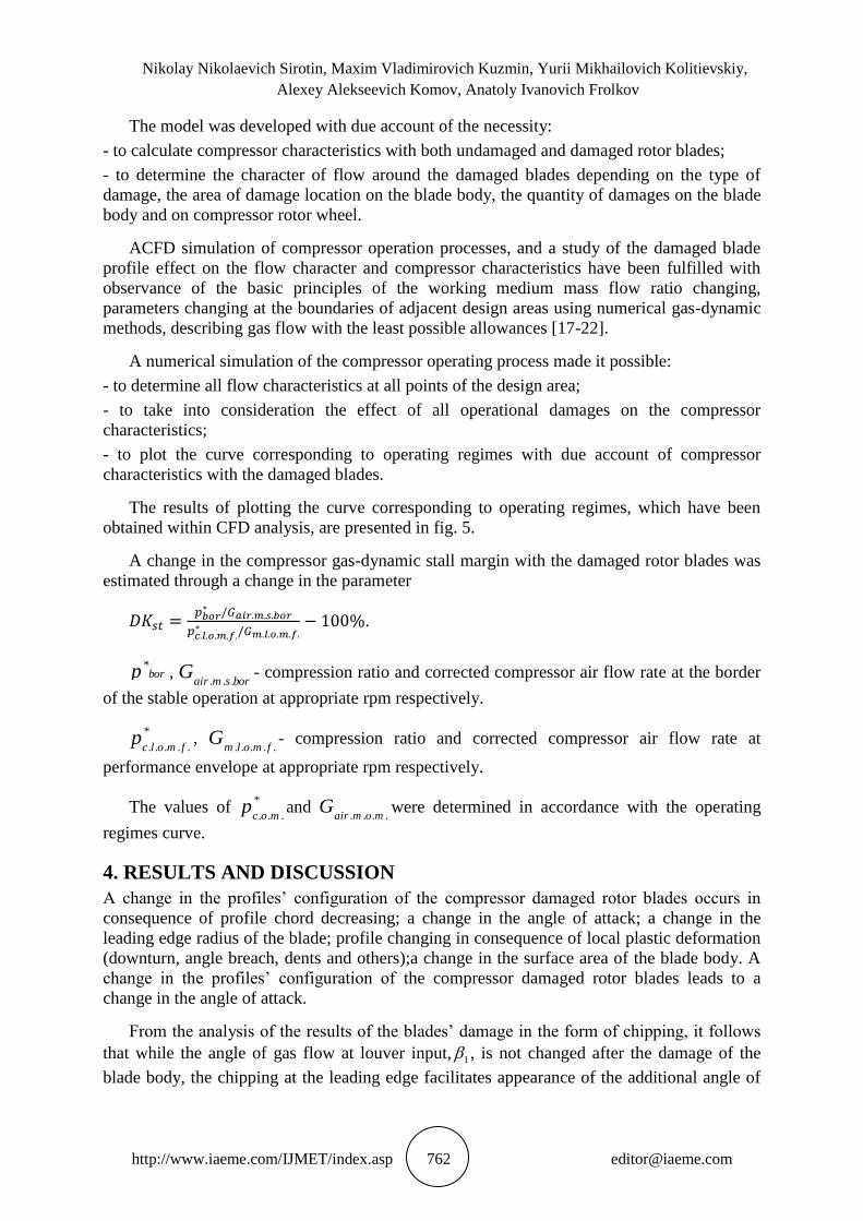
The model was developed with due account of the necessity:
- to calculate compressor characteristics with both undamaged and damaged rotor blades;
- to determine the character of flow around the damaged blades depending on the type of
damage, the area of damage location on the blade body, the quantity of damages on the blade
body and on compressor rotor wheel.
ACFD simulation of compressor operation processes, and a study of the damaged blade
profile effect on the flow character and compressor characteristics have been fulfilled with
observance of the basic principles of the working medium mass flow ratio changing,
parameters changing at the boundaries of adjacent design areas using numerical gas-dynamic
methods, describing gas flow with the least possible allowances [17-22].
A numerical simulation of the compressor operating process made it possible:
- to determine all flow characteristics at all points of the design area;
- to take into consideration the effect of all operational damages on the compressor
characteristics;
- to plot the curve corresponding to operating regimes with due account of compressor
characteristics with the damaged blades.
The results of plotting the curve corresponding to operating regimes, which have been
obtained within CFD analysis, are presented in fig. 5.
A change in the compressor gas-dynamic stall margin with the damaged rotor blades was
estimated through a change in the parameter
.
borp *,
. . .air m s borG - compression ratio and corrected compressor air flow rate at the border
of the stable operation at appropriate rpm respectively.
. . . . .c l o m fp *
, . . . . .m l o m f
G - compression ratio and corrected compressor air flow rate at
performance envelope at appropriate rpm respectively.
The values of . . .c o m
p *and
. . . .air m o mG were determined in accordance with the operating
regimes curve.
4. RESULTS AND DISCUSSION
A change in the profiles’ configuration of the compressor damaged rotor blades occurs in
consequence of profile chord decreasing; a change in the angle of attack; a change in the
leading edge radius of the blade; profile changing in consequence of local plastic deformation
(downturn, angle breach, dents and others);a change in the surface area of the blade body. A
change in the profiles’ configuration of the compressor damaged rotor blades leads to a
change in the angle of attack.
From the analysis of the results of the blades’ damage in the form of chipping, it follows
that while the angle of gas flow at louver input, 1 , is not changed after the damage of the
blade body, the chipping at the leading edge facilitates appearance of the additional angle of

Effect of Compressor Blades’ operational Damages Within an Aircraft Gas-Turbine Engine on its
Performance
http://www.iaeme.com/IJMET/index.asp 763 [email protected]
attack . ..1 1.b ch b
a b bD = - , where .
1 . .b chb is the design angle at the profile input, formed by
the line tangent to the centerline of the profile in the blade's damage point in the form of
chipping and louver front; .
1bb –is the design angle at profile input, formed by the line tangent
to the centerline of the undamaged blade profile and louver front. The sign of the additional
angle of attack aD is formed depending on the damage character (chipping, chipping with
plastic deformation and so on).
If plastic deformations at the boundary between the surface of the blade body and the
surface of the chipping are absent, then a positive additional angle of attack is formed. If
plastic deformations at the boundary between the surface of the blade body and the surface of
the chipping are present, then the sign of the angle of attack is formed depending on character
of the plastic deformations and may be not only positive but also negative.
A change in the blade profiles’ configuration leads to deterioration of their structural
strength and a change in the flow character around the damaged blades’ profile being an
object located within the air flow. The deterioration of the flow character around the
compressor blades leads to a change in the air consumption in the adjacent blade passages.
The velocity at the output from the blade passage is decreased. In channels adjacent to the
channel with the damaged blade, air consumption is either increased or decreased depending
on an increase or decrease in the angle of attack. Rotating stall may be formed, which leads to
a decrease in the effectiveness of the whole blade row with the damaged blade in the form of
chipping caused by an increase in the angles of attack.
A change in the working medium flow character around the damaged blades’ profile
relative to the design flow around the undamaged blades facilitates a change in the flow
structure; vortex flows’ generation; appearance of velocity and pressure profiles’ irregularities
behind the rotor wheel and behind the deflector in radial and circular directions; a change in
the air consumption in blade passages with the undamaged blades within the damaged
cascade; deterioration of the intake (suction) capacity of the damaged profile; velocity
decreasing at the output from the blade passage; deterioration of some other characteristics of
the operational process.
Changes in the flow structure facilitate a decrease in the compression process
effectiveness and a decrease in the effectiveness of the whole blade row, as well as a decrease
in the compressor stage stall margin and compressor operation in general. A decrease in the
compressor effectiveness and compressor gas-dynamic stall margin caused by the blades’
damage leads to a reduction in the aircraft safety factor and facilitates an increase in the
operational expenses connected with the necessity to provide additional conditions of the safe
operation and restoring of the damaged GTE.
The results of analytical estimation of effect of the compressor blades’ damage on a
change in its characteristics are as follows.
A change in the air consumption in the blade passage of the operational louver of the basic
cascade, formed between i and i +1 sections and two adjacent profiles, in case of the blades'
leading edge damage in the form of chipping, is characterized by the following equation:
k k k k1 1( )( )
a aG G c c F F r- D = - D + D
, (1)
Nikolay Nikolaevich Sirotin, Maxim Vladimirovich Kuzmin, Yurii Mikhailovich Kolitievskiy,
Alexey Alekseevich Komov, Anatoly Ivanovich Frolkov
http://www.iaeme.com/IJMET/index.asp 764 [email protected]
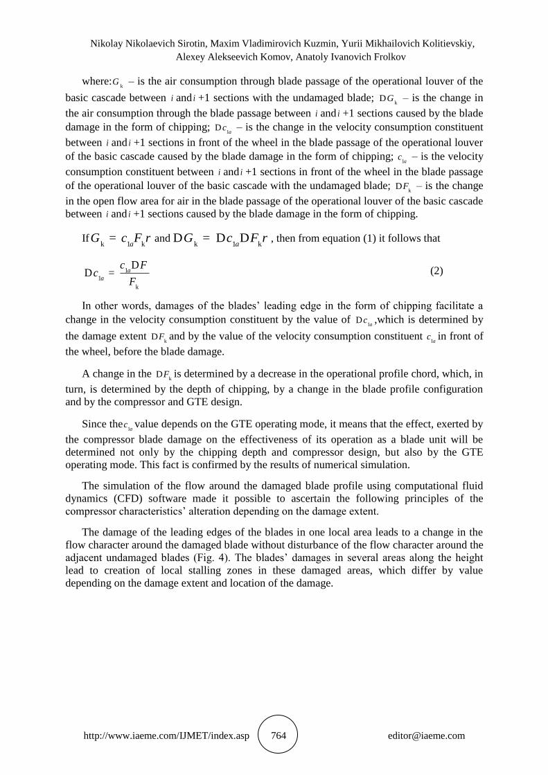
where:k
G – is the air consumption through blade passage of the operational louver of the
basic cascade between i and i +1 sections with the undamaged blade; k
GD – is the change in
the air consumption through the blade passage between i and i +1 sections caused by the blade
damage in the form of chipping; 1a
cD – is the change in the velocity consumption constituent
between i and i +1 sections in front of the wheel in the blade passage of the operational louver
of the basic cascade caused by the blade damage in the form of chipping; 1a
c – is the velocity
consumption constituent between i and i +1 sections in front of the wheel in the blade passage
of the operational louver of the basic cascade with the undamaged blade; k
FD – is the change
in the open flow area for air in the blade passage of the operational louver of the basic cascade
between i and i +1 sections caused by the blade damage in the form of chipping.
If and , then from equation (1) it follows that
(2)
In other words, damages of the blades’ leading edge in the form of chipping facilitate a
change in the velocity consumption constituent by the value of 1a
cD ,which is determined by
the damage extent k
FD and by the value of the velocity consumption constituent 1a
c in front of
the wheel, before the blade damage.
A change in the k
FD is determined by a decrease in the operational profile chord, which, in
turn, is determined by the depth of chipping, by a change in the blade profile configuration
and by the compressor and GTE design.
Since the1a
c value depends on the GTE operating mode, it means that the effect, exerted by
the compressor blade damage on the effectiveness of its operation as a blade unit will be
determined not only by the chipping depth and compressor design, but also by the GTE
operating mode. This fact is confirmed by the results of numerical simulation.
The simulation of the flow around the damaged blade profile using computational fluid
dynamics (CFD) software made it possible to ascertain the following principles of the
compressor characteristics’ alteration depending on the damage extent.
The damage of the leading edges of the blades in one local area leads to a change in the
flow character around the damaged blade without disturbance of the flow character around the
adjacent undamaged blades (Fig. 4). The blades’ damages in several areas along the height
lead to creation of local stalling zones in these damaged areas, which differ by value
depending on the damage extent and location of the damage.
k k1aG c F r=
k k1aG c F rD = D D
k
1
1
a
a
c Fc
F
DD =

Effect of Compressor Blades’ operational Damages Within an Aircraft Gas-Turbine Engine on its
Performance
http://www.iaeme.com/IJMET/index.asp 765 [email protected]
Figure 4 Flow character around the LPC blades; the blades’ damage in the form of 6 mm depth
chipping
The damage of the leading edges of the LPC 1st stage rotor wheel blades within the TFE
in two local areas will change the flow character around the blades in the zones of their
damage, which depends on the location of these zones along the height of the blade.
For the isolated 1st stage rotor wheel of the studied four-stage LPC, 50% blades of which
are damaged in the form of single chipping, characterized by the depth of bz =6.0 mm, located
on the leading edge at l =0.3h, in case of a specific mode of GTE operation gas-dynamic stall
margin may be reduced from 17% up to 13%.
The substantial deterioration of the characteristics . .
( , )m air m
f n Gp * = and ( , )m
f np h* *= of the
four-stage LPC with the damaged blades occurs in a certain range of LPC rotor speeds (rpm),
however, only in case of substantial damages of the blades’ leading edges in the form of
chippings. The most significant changes were registered for damages in the form of chippings
having the depth of zb >6.0 mm and for m
n »2
n mode of operation (Figs. 5, 6). For the
studied LPC model, chippings with the depth of not more than 0.5 mm are allowed without
their cutting-down, and those having the depth of not more than 2.0 mm are allowed after
cutting-down of such chippings.
If up to 50% of rotor blades of the isolated (without stator) rotor wheel are damaged and
have two chippings with the depth of bz =6.0 mm in the areas of l = 0.3handl =0.7h, then the
gas-dynamic stall margin may be reduced from 17% to 9%. The damaged rotor wheel,
considered together with stator, exerts more substantial effect on the deterioration of
characteristics than the isolated damaged rotor wheel.
A zero change of the gas-dynamic stall margin stKD for compressor with the damaged
rotor blades in case of other modes of GTE operation may be realized due to mutual
compensation of the changing parameters c
p * and . .air mG

Nikolay Nikolaevich Sirotin, Maxim Vladimirovich Kuzmin, Yurii Mikhailovich Kolitievskiy,
Alexey Alekseevich Komov, Anatoly Ivanovich Frolkov
http://www.iaeme.com/IJMET/index.asp 766 [email protected]
Figure 5 Characteristic curve . .( , )aim r mGf np* = for the four-stage LPC depending on the damage
extent (zb ), the area of its location (l),the quantity of the damaged blades (N).
Figure 6 Changes in characteristic curve . .
( , )m air m
Gf np * = for the four-stage LPC depending on
the plastic deformation extent of the rotor wheel blade body
The received data show that the operational damages of compressor blades exert the most
significant effect on a change in the compressor characteristics only for a certain mode of
GTE operation. For other modes, the effect of damages is negligible and may be ignored as a
factor exerting substantial effect on the effectiveness of the compressor operation as a blade
unit.
Chippings’ cutting-down and removal of definite zones of plastic deformations make it
possible partly to compensate a decrease in the fatigue strength of blades; however, these
procedures do not solve the problem of the damages’ effect on a change in the effectiveness
of GTE use with the repaired compressor blades.
Accordingly, safe GTE operation and providing of the required safety level of aircraft
flights may be reached only based on the data analysis pertinent to joint estimations of effect
exerted by compressor blades’ damages, both in terms of strength and in terms of the effect of
the damaged compressor blades on a possible decrease in its operation as a blade unit.

Effect of Compressor Blades’ operational Damages Within an Aircraft Gas-Turbine Engine on its
Performance
http://www.iaeme.com/IJMET/index.asp 767 [email protected]
The estimation of the effect of operational damages of compressor rotor blades on a
change in the GTE technical state and the compressor characteristics may be realized based
on the following approach.
Let the assumption be valid that the generation of ( )S t state of GTE may be represented
as the sum of the constituent states, generated by Z action and degradation (deterioration).
Then the following equation will be valid:
м м м( ) ( ) ( )Z D
j i j i j iS t S t S tD = D + D ,
where: м
( )j i
S tD – is the change in the technical state of thej-th element of thei-thGTE
module caused by external damaging factors and degradation;
м( )Z
j iS tD – is the change in the technical state of thej-th element ofthe i-th GTE module
caused by external damaging factors;
м( )D
j iS tD – is the change in the technical state of thej-th element ofthei-th GTE module
caused by degradation.
For GTE in general, the following equation will be valid:
( ) ( ) ( )Z DS t S t S tD = D + D ,
where: ( )ZS tD – is the change in the GTE technical state caused by external factors Z ,
which is characterized by the difference between the values of input parameters, in case of
zero affecting external factors, and the values of output parameters during monitoring
(diagnostics), in case of affecting external factors.
( )DS tD – is the change in the GTE technical state caused by degradation, which is
characterized by the difference between the values of output parameters, determining the
technical state in operational condition, and the values of output parameters during monitoring
(diagnostics), in case of zero affecting external factors.
Further, if there exists ( )S tD caused by the effect of damaging factors Z on GTE, then it
becomes possible to determine the reason of technical state changing.
If during estimation of GTE technical state, the distinction between a change in the
technical state caused by degradation, ( )DS tD , and a change in the technical state caused by
external factors, ( )ZS tD , are not taken into account, then such an approach may lead to
difficulties in establishing the real reason of technical state changing.
For GTE, the assumption is valid that GTE may be considered as the object of a "black
box" type, characterized by a set ( )i
Z t , a set of control actions ( )i
U t and a set of output
parameters ( )i
Y t , the elements of which, ( )r i
y t , are determined by the GTE state and by the
control actions’ values. Then the model, characterizing a change in the GTE state as an
operational object, may be presented as follows:

Nikolay Nikolaevich Sirotin, Maxim Vladimirovich Kuzmin, Yurii Mikhailovich Kolitievskiy,
Alexey Alekseevich Komov, Anatoly Ivanovich Frolkov
http://www.iaeme.com/IJMET/index.asp 768 [email protected]
stan , , , , ,u
M T U Z Y= W G,
where:{ }1 2
, , ..., , ...i r
T t t t t=– is the ordered finite set of time points, at which the
values of parameters of the set elements ( )Y t and ( )Z t have been measured;
( )U t – is a set of input control actions;
( )Z t – is a set of external affecting factors;
( )Y t – is a set of output parameters;
uW – is the space of ( )u t functions describing allowable input exposures;
Γ– is the space of ( )y t functions describing a change in the output parameters in time.
The explicit parameters of the GTE technical state ( )S t are not presented in this model.
However, the changes of ( )S t exert an effect on the character and sequence of the control
actions for compensation of disturbing factors exerting an effect on the GTE operation as an
operational object. In this case, ( )S t is considered as the state generated under the effect of
the external affecting factors and degradation, and is determined by a finite set consisting of
K elements, 1( ) ,..., ,...,k KS t S S S ,
where: kS – is the actual k -th GTE technical state, generated during operation under
effect of real external affecting factors f
kZ .
Then estimation of operation quality, depending on the GTE technical state, may be
performed using the following algorithm:
1. If
( ) ( ) ( ) max0
i i i iY t Y t Y tD = - £
,
( ) ( ) ( ) min0
i i i iY t Y t Y tD = - ³
,
then GTE is functionally operative.
Here ( ) maxi iY t and ( ) mini i
Y t –arethe maximum and minimum allowable values of the
output parameter, respectively.
2. If
( ) ( ) ( ) ( )TUi i ref i iY t Y t Y t Y tD = - > D
,
then technical state within the normal operation area has deteriorated during operation.
Here: ( )stani
Y t – is the output parameter value following the reference standard;
Effect of Compressor Blades’ operational Damages Within an Aircraft Gas-Turbine Engine on its
Performance
http://www.iaeme.com/IJMET/index.asp 769 [email protected]
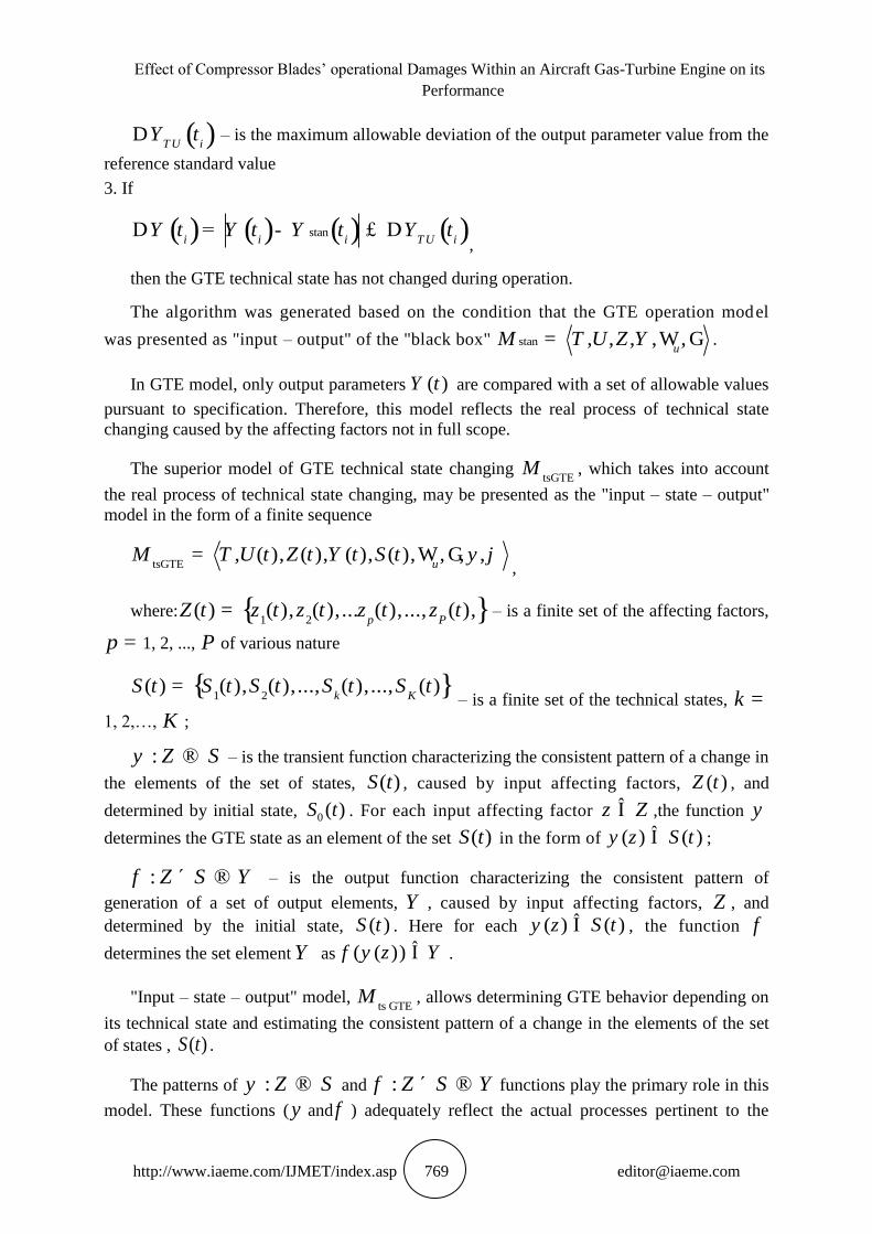
( )T U iY tD – is the maximum allowable deviation of the output parameter value from the
reference standard value
3. If
( ) ( ) ( ) ( )stani i i TU i
Y t Y t Y t Y tD = - £ D,
then the GTE technical state has not changed during operation.
The algorithm was generated based on the condition that the GTE operation model
was presented as "input – output" of the "black box" stan , , , , ,u
M T U Z Y= W G .
In GTE model, only output parameters ( )Y t are compared with a set of allowable values
pursuant to specification. Therefore, this model reflects the real process of technical state
changing caused by the affecting factors not in full scope.
The superior model of GTE technical state changing tsGTE
M , which takes into account
the real process of technical state changing, may be presented as the "input – state – output"
model in the form of a finite sequence
tsGTE, ( ), ( ), ( ), ( ), , , ,
uM T U t Z t Y t S t y j= W G
,
where: { }1 2( ) ( ), ( ),... ( ),..., ( ),
p PZ t z t z t z t z t= – is a finite set of the affecting factors,
p = 1, 2, ..., P of various nature
{ }1 2( ) ( ), ( ),..., ( ),..., ( )
k KS t S t S t S t S t=
– is a finite set of the technical states, k =1, 2,…, K ;
: Z Sy ® – is the transient function characterizing the consistent pattern of a change in
the elements of the set of states, ( )S t , caused by input affecting factors, ( )Z t , and
determined by initial state, 0 ( )S t . For each input affecting factor z ZÎ ,the function y
determines the GTE state as an element of the set ( )S t in the form of ( ) ( )z S ty Î ;
: Z S Yf ´ ® – is the output function characterizing the consistent pattern of
generation of a set of output elements, Y , caused by input affecting factors, Z , and
determined by the initial state, ( )S t . Here for each ( ) ( )z S ty Î , the function f
determines the set element Y as ( ( ))z Yf y Î .
"Input – state – output" model, ts GTE
M , allows determining GTE behavior depending on
its technical state and estimating the consistent pattern of a change in the elements of the set
of states , ( )S t .
The patterns of : Z Sy ® and : Z S Yf ´ ® functions play the primary role in this
model. These functions (y and f ) adequately reflect the actual processes pertinent to the

Nikolay Nikolaevich Sirotin, Maxim Vladimirovich Kuzmin, Yurii Mikhailovich Kolitievskiy,
Alexey Alekseevich Komov, Anatoly Ivanovich Frolkov
http://www.iaeme.com/IJMET/index.asp 770 [email protected]
technical state changing, provided they take into account the real operation conditions and
actual state of operating component. Therefore, simulation and development of methods
should be performed with due account of the real operation conditions and actual state of
operating component.
Changing GTE technical state caused by external affecting factors and degradation is
characterized by a change in the output parameters’ values in the space of these parameters.
The function : Z Sy ® determines the consistent pattern of a change in the elements of the
set ( )S t caused by input affecting factors ( )Z t . The function : Z S Yf ´ ®
characterizes the consistent pattern of the generation of elements of the set of outputsY under
effect of the input affecting factors Z and state parameters ( )S t . These functions determine
the consistent pattern of GTE technical state changing.
Thus, generation of GTE technical state under external affecting factors and degradation is
determined by the patterns of y and f functions depending on the operating factors. During
estimation of reliability of the created mathematical model describing a change in the GTE
technical state, reproducibility of the developed model in different experimental and practical
operational conditions has been revealed and qualitative coincidence of the results obtained
by the authors of this article with the results presented in independent publications devoted to
this topic [23-26] has been found.
5. CONCLUSIONS
The results of the performed investigation reflect an interest of experts involved in practical
aircraft GTE operation in data, pertinent to character of the operational damages of the
compressor blades during compressor operation as a blade unit. The performed numerical
simulation of the compressor operation with the damaged blades has shown that the obtained
simulation results agree well with the results of the GTE operation in real conditions.
The analytical estimation of the compressor blade operational damages’ effect on its
parameters as a blade unit has shown that the principal parameters exerting an effect on a
change in the consumption constituent of the flow velocity at its input into the compressor
stage, in case of the blades’ damage, are the value of the consumption constituent of the flow
velocity in front of the rotor wheel before the blades’ damage, mode of operation and the
damage extent.
A change in the compressor characteristics in case of the damaged blades facilitates a
change in the GTE technical state, the level of its operating capacity and evidences on the fact
that the damaged blades exert an effect on the compressor, being the blade unit, depending on
the compressor design, GTE design and mode of its operation.
The results of numerical simulation have shown that the compressor blades’ damages
exert the most substantial effect on a change in the compressor characteristics only for the
case of a certain mode of GTE operation, while for other modes effect of damages is
negligible and should not be considered as the factor exerting an effect on the effectiveness of
the compressor operation as a blade unit.
The performed numerical simulation of the effect of the compressor rotor blades’ damages
on the compressor operation as a blade unit has shown that the simulation results based on the
accepted analytical model agree well with the actual physical processes and concepts. The
simulation results also agree well with the results of analytical investigations, in which the
Effect of Compressor Blades’ operational Damages Within an Aircraft Gas-Turbine Engine on its
Performance
http://www.iaeme.com/IJMET/index.asp 771 [email protected]
suggested model of consumption constituent changing depending on rotor blades damage has
been used.
The results of investigations have shown that it is appropriate to perform estimation of
effect of the compressor blades’ damages in an integrated manner, both with due account of a
decrease in the fatigue strength of the damaged blades, and with due account of the
compressor blade damages’ effect on a decrease in the effectiveness of the compressor
operation as a blade unit, on a change in the fuel consumption and effectiveness of GTE use.
It is appropriate to perform such estimation at the stage of GTE creation. The estimation
of the compressor characteristics with the damaged blades at the stage of GTE creation will
make it possible to manufacture more reliable and effective GTEs, and during operation to use
the endurance capabilities of aircraft GTEs more safely and effectively and to forecast a
change in the compressor characteristics under effect of the operational damaging factors. If
during operation, the task will appear to determine the reasons of GTE unstable operation,
then usage of numerical simulation of compressor operation with the damaged blades will
allow shortening the terms of investigations aimed to determine the reasons of GTE unstable
operation and improving the quality of investigation.
The estimation of the effect of the operational damages of compressor rotor blades on a
change in the GTE technical state and on a change in the compressor characteristics may be
realized based on the following approach.
Let the assumption be valid that the generation of the ( )S t state of GTE may be
presented as a sum of states of the constituent components, modules, structural elements,
generated by the affecting factors Z and in consequence of degradation.
Further, if estimations of changes in the GTE technical state, ( )S tD , and estimations of
changes in the GTE technical state caused by damaging factors, Z , are available, then it is
quite possible to determine the reason of technical state changing in the operational capability
area and to estimate the GTE performance and technical state with particular detailing
following the respective algorithm. The algorithm is developed on the basis of the assumption
that the GTE operation model is represented by the "black box", as "input – output".
The model of a change in the GTE technical state, in which the GTE is considered as an
operational and diagnostics object, may be presented as the "input – state – output" model,
which allows explaining the observed behavior of the GTE depending on its technical state
and to estimate the consistent pattern of a change in the elements of the set of states.
REFERENCES
[1] Aviatsionnye pravila Chast 33 "Normy letnoi godnosti dvigatelei vozdushnykh sudov"
[Flying Regulations Part 33 "Airworthiness Standards for Aircraft Engines"]. Interstate
Aviation Committee, OAO "Aviaizdat", 2012, pp. 78.
[2] Gritsin, A.V., Kocherov, E.P., Rempel, A.P. and Samoilov, V.A. Issledovanie i
normirovanie dopustimykh zaboin na rabochikh lopatkakh kompressora na primere
dvigatelya NK-12 [Investigation and Rating of the Allowable Chippings on Compressor
Rotor Blades as Exemplified by NK-12 Engine]. Vestnik Samarskogo Gosudarstvennogo
Aerokosmicheskogo Universiteta, 3(19), 2009, pp. 221-229.
[3] OST 1 00304-79. Lopatki gazovykh turbinnykh dvigatelei. Normirovanie povrezhdenii
lopatok kompressorov ot popadaniya postoronnikh predmetov [Branch Standard OST 1

Nikolay Nikolaevich Sirotin, Maxim Vladimirovich Kuzmin, Yurii Mikhailovich Kolitievskiy,
Alexey Alekseevich Komov, Anatoly Ivanovich Frolkov
http://www.iaeme.com/IJMET/index.asp 772 [email protected]
00304 – 79. Blades of Gas-Turbine Engines. Rating of Compressor Blades Damages
Caused by Foreign Objects Strike], 1979.
[4] Sirotin, N.N., Marchukov, E.Yu. and Novikov, A.S. Povrezhdaemost I rabotosposobnost
aviatsionnykh GTD. Spravochnik [Damaging and Operating Capacity of Aircraft GTE.
Reference Book]. Moscow: Nauka, 2015, pp. 551.
[5] Ghenaiet, A., Tan, S.C. and Elder, R.L. Experimental Investigation of Axial Fan Erosion
and Performance Degradation. Proceedings of the Institution of Mechanical Engineers,
Part A: Journal of Power and Energy, 218(6), 2004, pp. 437-446.
[6] Suzuki, M. and Yamamoto, M. Numerical Simulation of Sand Erosion Phenomena in a
Single-Stage Axial Compressor. Journal of Fluid Science and Technology, 6(1), 2011.
[7] Wildlife Strikes to Civil Aircraft in the United States 1990-2013. Federal Aviation
Administration National Wildlife Strike Database. Report No.20, July, 2014.
[8] Wilbeck, J.S. Impact Behavior of Low Strength Projectiles: Technical Report: AFML-TR-
77-134. Air Force Materials Laboratory, Air Force Wright Aeronautical, 1978.
[9] Shorr, B., Melnikova, G. and Tishchenko, N. Numerical and Experimental Analysis of a
Large Bird Impact on Fan Blades forthe Certification Purpose. Athens: International Bird
Strike Committee, 2005.
[10] Lavoie, M.-A., Gakwaya, NejadEnsan, M., and Zimcik, D.G. Validation of Available
Approaches for Numerical Bird Strike Modeling Tools. International Review of
Mechanical Engineering, 1(4), 2007, pp. 380-389.
[11] Inozemtsev, A.A., Nykhamkin, M.A. and Sandratskii, V.L. Osnovy konstruirovaniya
aviatsionnykh dvigatelei i energeticheskikh ustanovok. Tom II. Obshchie svedeniya.
Kompressory. Kamery sgoraniya. Forsazhnye kamery. Turbiny. Vykhodnye ustroistva
[Aircraft Engines and Power Generating Systems’ Design Foundations. Vol. 2: Aircraft
Engines and Power Generating Systems’ Design Foundations. General Information.
Compressors. CombustionChambers. Augmenters. Turbines. OutputDevices]. Moscow:
Mashinostroenie, 2008, pp. 366.
[12] Cumpsty, N. Aerodynamika kompressorov [Aerodynamics of Compressors]. Moscow:
Mir, 2000, pp. 688.
[13] Stechkin, B.S., Kazandzhan, P.K., Alekseev, L.P., Govorov, A.N., Nechaev, Yu.N. and
Fedorov, R.M. Teoriya reaktivnykh dvigatelei. Lopatochnye mashiny [Jet Engines
Theory. Blade Units]. Moscow: Gosudarstvennoe izdatelstvo oboronnoi promyshlennosty,
1956, pp. 543.
[14] Kholshevnikov, K.V., Emin, O.N. and Mitrokhin, V.N. Teoriya i raschet aviatsionnykh
lopatochnykh mashin [Theory and Analysis of Aircraft Blade Units]. Moscow:
Mashinostroenie, 1986, pp. 432.
[15] Shulekin, V.T. Kharakteristika stupeni osevogo kompressora GTD s povrezhdyonnimy
lopatkami [Characteristics of GTE Axial Compressor with the Damaged Blades].
Moscow: MGTUGA, 2008, pp. 99.
[16] Lewis, R.I. Turbomachinery Performance Analysis. ElsevierScience & Technology
Books, 1996.
[17] Avgustinovich, V.G., Shmotin, Yu.N., Sipatov, A.M., Rumyantsev, D.B. et al. Chislennoe
modelirovanie nestatsionarnykh yavlenii v gazoturbinnykh dvigatelyakh [Numerical
Simulation of Non-Stationary Phenomena in Gas-turbine Engines]. Moscow:
Mashinostroenie, 2005, pp. 535.
[18] Fletcher, K. Vychislitelnye metody v dinamike zhidkostei [Computational Methods in
Liquids Dynamics]. Moscow: Mir, 1991, pp. 1056.
Effect of Compressor Blades’ operational Damages Within an Aircraft Gas-Turbine Engine on its
Performance
http://www.iaeme.com/IJMET/index.asp 773 [email protected]
[19] Anderson, D., Tannehill, G. and Pletcher, R. Vychislitelnaya gidromekhanika i
teploobmen [Computational Hydromechanics and Heat Exchange]. Moscow: Mir, 1990,
pp. 384.
[20] Fang, Y., Hu, Z., Teng, H., Jiang, Z. and Ng, H.D. Numerical Study of Inflow
Equivalence Ratio Inhomogeneity on Oblique Detonation Formation in Hydrogen-Air
Mixtures. Journal of Aerospace Science and Technology, 71, 2017, pp. 256-263.
[21] Sargent, R.G. Verifying and Validating Simulation Models. In: Proceedings of the 2014
Winter Simulation Conference, December 7-10, 2014, Westin Savannah Harbor Resort,
Savannah, GA, 2014.
[22] Claus, R.W. and Townsend, S. A Review of High Fidelity, Gas-Turbine Engine
Simulations. In: 27th International Congress of The Aeronautical Sciences, Stockholm:
ICAS, 2010.
[23] Kirpichev, A.I., Kuleshov, A.A. and Ratenko, D.V. Otsenka vozmozhnosti i perspektiv
perevoda dvigatelei TV3-117VM, VK-2500 v dvukhtoplivnyi variant
(ASKT/Aviakerosin) [Estimation of Possibilities and Prospects of TV3-117VM, VK-2500
Engines Transfer for Double-Fuel Version (ASKT/Aviakerosin)]. Nauchnyi Vestnik
GosNIIGA, 4(315), 2014, pp. 29-38.
[24] Kuleshov, A.A. and Ratenko, D.V. Problemy i perspektivy ispolzovaniya gazomotornogo
topliva v aviatsii na sovremennom etape [Problems and Prospects of Gas-Engine Fuel Use
for Aircrafts at Present Stage]. Nauchnyi Vestnik GosNIIGA, 5(316), 2014, pp. 15-24.
[25] Sirotin, N.N., Marakhovskii, I.V. and Kirsanov, A.R. Metodika otsenki adekvatnosti
povrezhdaemosti gazoturbinnogo dvigatelya, vosproizvedennoi pri chislennom
modelirovanii realnoi povrezhdaemosti [Method for Adequacy Estimation of Gas-turbine
Engine Damaging Reproduced in Numerical Simulation of Actual Damaging]. Nauchnyi
Vestnik GosNIIGA, 11(322), 2015, pp. 82-93.
[26] Shapkin, V.S. and Pleshakov, A.I. FGUP GosNII GA v Federalnoi sisteme monitoring
rezultativnosti deyatelnosti nauchnykh organizatsii [FSUE GosNII GA Rating Established
by Federal System for Monitoring of Effectiveness of Scientific Institutions Activities].
Nauchnyi Vestnik GosNIIGA, 11(322), 2015, pp. 67-78.
[27] MD Khaleel, Marampalli Shilpa and L.Farooq Modeling and CFD Analysis on one Stage
of Turbine of Gas Turbine Engine. International Journal of Civil Engineering and
Technology, 8(5), 2017, pp. 638–645.
[28] Yousif Khudhair Abbas, Effect of Sideslip Angle on the Balance of Aircraft Moments
Through Steady - State Spin. International Journal of Civil Engineering and Technology,
8(10), 2017, pp. 627 – 633
[29] K. V. Chaudhari, D. B. Kulshreshtha, S. A. Channiwala, Design And Experimental
Investigations Of Pressure Swirl Atomizer Of Annular Type Combustion Chamber For 20
Kw Gas Turbine Engine. International Journal of Advanced Research in Engineering and
Technology (IJARET), 3(2), 2012, pp.311–321


![Energy, Exergy and Thermoeconomics Analysis of Water ... · the compressor blades [9]. The water droplets carryover and the resulting damage to the compressor blades, limit the use](https://static.fdocuments.us/doc/165x107/5fb09dc937f8ed239348c22a/energy-exergy-and-thermoeconomics-analysis-of-water-the-compressor-blades-9.jpg)