Effect of Compensation and Arbitrary Sampling in ... · This can be implemented by using efficient...
13
Research Journal of Applied Sciences, Engineering and Technology 6(4): 609-621, 2013 ISSN: 2040-7459; e-ISSN: 2040-7467 © Maxwell Scientific Organization, 2013 Submitted: August 29, 2012 Accepted: September 24, 2012 Published: June 20, 2013 Corresponding Author: Rajeev Ratan, Electronics and Communication Engineering Department, Thapar University, Patiala- 147004, Punjab, India 609 Effect of Compensation and Arbitrary Sampling in interpolators for Different Wireless Standards on FPGA Platform Rajeev Ratan, Dr. Sanjay Sharma and Dr. Amit K. Kohli Electronics and Communication Engineering Department, Thapar University, Patiala-147004, Punjab, India Abstract: In any communication system, it is desired to convert very high sampling frequency to processor frequency. This can be implemented by using efficient use of Multirate Filters. In this paper, the Multi rate filters have been implemented very effectively on FPGA Platform. Also, it has been shown that how performance of Multi rate filters can be improved using different techniques at different sampling rates. The filter structures suggested here have wide applications in the field of ADC (Analog to Digital Converter), DUC (Digital Up Converter)/DDC(Digital Down Converter) and in almost every stage of communication system wherever convolution is being done. The results also show that proposed multi rate filter structures can be used very effectively and efficiently in designing and development of very large scale integration of Digital communication system. Keywords: Field Programmable Gate Arrays (FPGA), Global System for Mobile communication (GSM), interpolators, Universal Mobile Telecommunications System (UMTS), Wideband Code Division Multiple Access (WCDMA), Worldwide Interoperability for Microwave Access (WIMAX) INTRODUCTION The digital filters have emerged as a strong option for removing noise, shaping spectrum, and minimizing inter-symbol interference in communication architectures. These filters have become popular because their precise reproducibility allows design engineers to achieve performance levels that are difficult to obtain with analog filters. The main building blocks of any communication system are Multi rate systems. Their function is to alter the rate of the discrete-time signals, by adding or deleting a portion of the signal samples. An essential component of cost effective DSP algorithms is multi rate signal type filters. Such filters offer extremely efficient structures to simultaneously perform digital filtering, spectral translation, interpolation, and decimation in both non-recursive and recursive structures. Field-Programmable gate Array (FPGA) has become an extremely cost-effective means of off-loading computationally intensive digital signal processing algorithms to improve overall system performance. The basic blocks of modern digital communication system are multi rate systems. The main function of multi rate systems is to either increase or decrease the sampling rate. These systems are very useful for signal analysis, denoising, compression and so forth. These systems have increasingly found applications in recent trends in the areas of digital communication. Multi rate filters provide extremely efficient structures to simultaneously perform interpolation and decimation in the digital communication system. These filters have become popular because their precise reproducibility allows design engineers to achieve performance levels that are difficult to obtain with analog filters. In this paper, it has been shown that how compensation improves the performance of digital filters, therefore CIC filter with and without compensation technique is implemented on FPGA platform and their results have been compared. Fractional sampling rate is the need of all modern communication systems. The Farrow structure is an efficient structure to implement the interpolation filter for fractional rate change as well as for any arbitrary rate change factor. In this work, the Farrow filters have been implemented for fractional delay and arbitrary change in sample rate conversion on FPGA platform which is the need of any modern digital communication system. Both of these filters gives a better performance than the common filter structures in terms of speed of operation, cost and power consumption in real-time. CIC FILTERS The Cascaded Integrator-Comb (CIC) filter is a class of hardware-efficient linear phase Finite Impulse Response (FIR) digital filters. CIC filters achieve
Transcript of Effect of Compensation and Arbitrary Sampling in ... · This can be implemented by using efficient...

Research Journal of Applied Sciences, Engineering and Technology 6(4): 609-621, 2013 ISSN: 2040-7459; e-ISSN: 2040-7467 © Maxwell Scientific Organization, 2013 Submitted: August 29, 2012 Accepted: September 24, 2012 Published: June 20, 2013
Corresponding Author: Rajeev Ratan, Electronics and Communication Engineering Department, Thapar University, Patiala-
147004, Punjab, India 609
Effect of Compensation and Arbitrary Sampling in interpolators for Different Wireless
Standards on FPGA Platform
Rajeev Ratan, Dr. Sanjay Sharma and Dr. Amit K. Kohli Electronics and Communication Engineering Department, Thapar University,
Patiala-147004, Punjab, India Abstract: In any communication system, it is desired to convert very high sampling frequency to processor frequency. This can be implemented by using efficient use of Multirate Filters. In this paper, the Multi rate filters have been implemented very effectively on FPGA Platform. Also, it has been shown that how performance of Multi rate filters can be improved using different techniques at different sampling rates. The filter structures suggested here have wide applications in the field of ADC (Analog to Digital Converter), DUC (Digital Up Converter)/DDC(Digital Down Converter) and in almost every stage of communication system wherever convolution is being done. The results also show that proposed multi rate filter structures can be used very effectively and efficiently in designing and development of very large scale integration of Digital communication system. Keywords: Field Programmable Gate Arrays (FPGA), Global System for Mobile communication (GSM),
interpolators, Universal Mobile Telecommunications System (UMTS), Wideband Code Division Multiple Access (WCDMA), Worldwide Interoperability for Microwave Access (WIMAX)
INTRODUCTION
The digital filters have emerged as a strong option
for removing noise, shaping spectrum, and minimizing inter-symbol interference in communication architectures. These filters have become popular because their precise reproducibility allows design engineers to achieve performance levels that are difficult to obtain with analog filters. The main building blocks of any communication system are Multi rate systems. Their function is to alter the rate of the discrete-time signals, by adding or deleting a portion of the signal samples.
An essential component of cost effective DSP algorithms is multi rate signal type filters. Such filters offer extremely efficient structures to simultaneously perform digital filtering, spectral translation, interpolation, and decimation in both non-recursive and recursive structures. Field-Programmable gate Array (FPGA) has become an extremely cost-effective means of off-loading computationally intensive digital signal processing algorithms to improve overall system performance.
The basic blocks of modern digital communication system are multi rate systems. The main function of multi rate systems is to either increase or decrease the sampling rate. These systems are very useful for signal analysis, denoising, compression and so forth. These systems have increasingly found applications in recent
trends in the areas of digital communication. Multi rate filters provide extremely efficient structures to simultaneously perform interpolation and decimation in the digital communication system. These filters have become popular because their precise reproducibility allows design engineers to achieve performance levels that are difficult to obtain with analog filters. In this paper, it has been shown that how compensation improves the performance of digital filters, therefore CIC filter with and without compensation technique is implemented on FPGA platform and their results have been compared. Fractional sampling rate is the need of all modern communication systems. The Farrow structure is an efficient structure to implement the interpolation filter for fractional rate change as well as for any arbitrary rate change factor. In this work, the Farrow filters have been implemented for fractional delay and arbitrary change in sample rate conversion on FPGA platform which is the need of any modern digital communication system. Both of these filters gives a better performance than the common filter structures in terms of speed of operation, cost and power consumption in real-time.
CIC FILTERS
The Cascaded Integrator-Comb (CIC) filter is a
class of hardware-efficient linear phase Finite Impulse Response (FIR) digital filters. CIC filters achieve

Res. J. Appl. Sci. Eng. Technol., 6(4): 609-621, 2013
610
Fig. 1: Decimating CIC filter (3 stage)
Fig. 2: Interpolating CIC filter (3 stage) sampling rate decrease (decimation) and sampling rate increase (interpolation) without using multipliers. A CIC filter consists of an equal number of stages of ideal integrator filters and comb filters. Its frequency response may be tuned by selecting the appropriate number of cascaded integrator and comb filter pairs. The highly symmetric structure of a CIC filter allows efficient implementation in hardware. However, the disadvantage of a CIC filter is that its pass band is not flat, which is undesirable in many applications. Fortunately, this problem can be alleviated by a compensation filter. The CIC filter can also be implemented very efficiently in hardware due to its symmetric structure. A CIC decimator would have N cascaded integrator stages clocked at fs, followed by a rate change by a factor R, followed by N cascaded comb stages running at fs/R. Figure 1 show the three stage decimating CIC filter. A CIC interpolator would be N cascaded comb stages running at fs/R, followed be a zero-stuffer, followed by N cascaded integrator stages running at fs. Figure 2 shows the three stage interpolating CIC filter.
The transfer function of the CIC filter in z-domain is given in Eq. (1) (Hogenauer, 1981).
𝐻𝐻(𝑧𝑧) = �1−𝑧𝑧−𝑘𝑘
1−𝑧𝑧−1�𝐿𝐿
(1)
In equation (1), K is the oversampling ratio and L is the order of the filter. The numerator (1–z -k) L represents the transfer function of a differentiator and the denominator (1–z -1)L indicates the transfer function of an integrator.
A very poor magnitude characteristic of the comb filter is improved by cascading several identical comb filters. The transfer function H(z) of the multistage comb filter composed of K identical single-stage comb filters is given by:
Fig. 3: CIC filter gain responses: single-stage K= 1, two-stage
K=2, three-stage K=3 and four-stage
Fig. 4: CIC filter gain response: Pass-band droop for Fig. 2
𝐻𝐻(𝑧𝑧) = �1𝑁𝑁
1−𝑧𝑧−𝑁𝑁
1−𝑧𝑧−1�𝐾𝐾
(2)
Figure 3 shows how the multistage realization improves the selectivity and the stop-band attenuation of the overall filter: the selectivity and the stop-band attenuation are augmented with the increase of the number of comb filter sections (Meyer-Bease, 2007; Ljiljana, 2009). The filter has multiple nulls with

Res. J. Appl. Sci. Eng. Technol., 6(4): 609-621, 2013
611
Fig. 5: Two-stage decimator composed of a CIC filter and an FIR filter: (a) Cascade implementation, (b) Single-stage equivalent
Fig. 6: Two-stage interpolator composed of an FIR filter in the first and CIC filter in the second stage: (a) Cascade
implementation, (b) Single-stage equivalent multiplicity equal to the number of the sections (K). Consequently, the stop-band attenuation in the null intervals is very high. Figure 4 illustrates a monotonic decrease of the magnitude response in the pass-band, called the pass-band droop.
COMPENSATION OF CIC FILTER
A CIC filter can be used as a first stage in
decimation when the overall conversion ratio M is factorable as:
𝑀𝑀 = 𝑁𝑁 × 𝑅𝑅 (3)
The overall factor-of-M sampling rate conversion system can be implemented by cascading a factor-of-N CIC decimator and a factor-of-R FIR decimator as shown in Fig. 5a. The corresponding single-stage equivalent is given in Fig. 5b.
When constructing an interpolator with a conversion factor L factorable as:
𝐿𝐿 = 𝑅𝑅 × 𝑁𝑁 (4)
It might be beneficial to implement the second (last) stage as a CIC interpolator. The first stage is usually implemented as an FIR filter. Figure 6a, depicts the two-stage interpolator consisting of the cascade of a factor-of-R FIR interpolator and a factor-of-N CIC interpolator. The corresponding single-stage equivalent is shown in Fig. 6b.
In the two-stage solutions of Fig. 5 and 6, the role of CIC decimator (interpolator) is to convert the sampling rate by the large conversion factor N, whereas the FIR filter T (z) provides the desired transition band of the overall decimator (interpolator) and compensates the pass-band characteristic of the CIC filter (Crochiere and Rabiner, 1983; Ricardo, 2008; Vesma, 1999; Farrow, 1988).
FILTERS WITH NON INTEGER DECIMATION
FACTOR: FARROW FILTERS
When the decimation factor 1/R or the interpolation factor R is an integral value, then the conversion of sampling rate can be performed conveniently with the aid of fixed digital filters (Hentschel and Fettweis, 2000a). In case of a scenario where the factors are irrational, it will be impossible to use fixed digital filters directly. Moreover, if R is considered as the ratio of two relatively large prime integers, then, in the case of the conventional polyphone implementation, it is quiet essential that the orders of the required filter become very large. In nutshell, it means that a large number of coefficients need to be stored in coefficient memory. In sampling rate conversion by non-integer factor, it is required to determine the values between existing samples. In this case, it is very convenient to use interpolation filters. Among them, polynomial-based filters are generally assumed to provide an efficient implementation form
Res. J. Appl. Sci. Eng. Technol., 6(4): 609-621, 2013
612
Fig. 7: Multirate far row filter directly in digital domain. Such filters witness an effective implementation through Farrow structure or its higher version (Babic and Renfors, 2005; Babic et al., 2001).
Consider the diagram shown in Fig. 7. The dashed line separates the filter into a section running at the input signal’s sampling-rate and a section running at the output sampling-rate. Note that the output is re-labeled to be y[m] rather than y[n]. This is due to different input and output rates. Notably, the fractional delay now denoted βm will now change at every instant an output sample occurs (Vesma and Saramaki, 2007; Jiang and Jr, 1997; Dolecek and Mitra, 2005).
One can use Farrow structure or its modifications directly. However, in many cases, it becomes more efficient to use cascaded structures engineered by the modification of the Farrow structure and fixed FIR, or
multistage FIR filter (Abu-Al-Saud and Stuber, 2003; Hentschel and Fettweis, 2000b).
MATERIALS AND METHODS
Field-Programmable gate Array (FPGA) has
become an extremely cost-effective means of off-loading computationally intensive digital signal processing algorithms to improve overall system performance.
In this paper, CIC filter with and without compensation technique are implemented on FPGA. Also the Farrow filters are implemented for fractional delay and arbitrary change in sample rate conversion. Both of these filters gives a better performance than the common filter structures in terms of speed of operation, cost, and power consumption in real-time. These filters are implemented in Altera Stratix-II-EP2S15F484C3 FPGA and simulated with the help of Quartus II v9.1sp2. These filters can work in real time.
The proposed work has been carried out at Thapar University, Patiala and Punjab, INDIA. The author is a research scholar at Thapar University, Patiala and Punjab, INDIA since December 2009 – till date. This paper represents the conclusion of one module of the whole work carried out by the author during his research tenure.
RESULTS AND DISCUSSION
This section illustrates the properties of the
proposed filters by means of design.
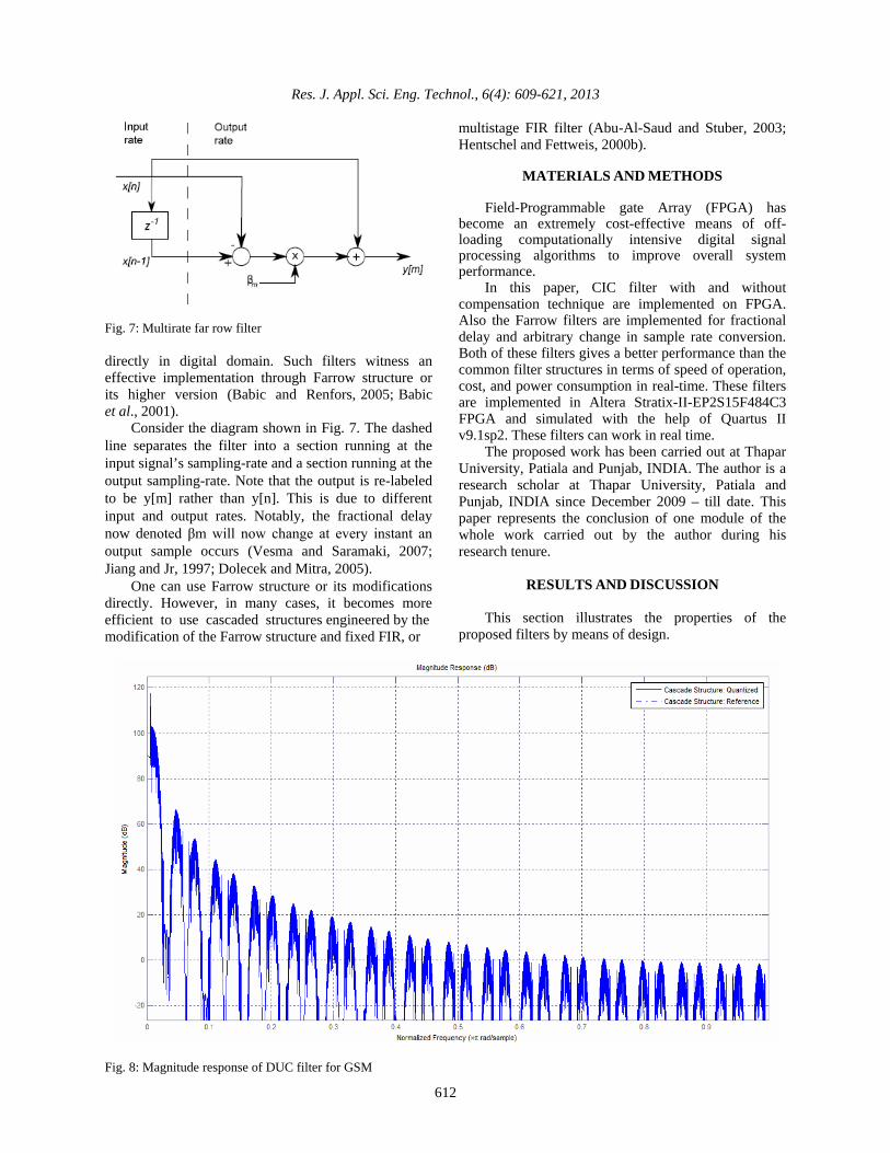
Fig. 8: Magnitude response of DUC filter for GSM

Res. J. Appl. Sci. Eng. Technol., 6(4): 609-621, 2013
613
Fig. 9: Modelsim simulation of DUC filter design for GSM Design examples of multistage CIC filter with compensation techniques: This subsection illustrates the simulation results of DUC filter design for various wireless standards using the multistage CIC filters with compensation techniques: Simulation results of DUC filter design for GSM: The specifications for DUC Filter for GSM are as follows: • Input Sampling Frequency :34.667 KHz • Output Sampling Frequency:270.83 KHz • Pass-band Edge :0.08 MHz • Stop-band Edge :0.1 MHz • Pass-band Ripple :0.1 dB • Stop-band Attenuation :65 dB
Using the above specifications, the multistage filter is implemented. The response of the filter is shown in Fig. 8 and its simulation is shown in Fig. 9.
Simulation results of DUC filter design for WCDMA: The specifications for DUC Filter for WCDMA are as follows: • Input Sampling Frequency : 3.84 MHz • Output Sampling Frequency: 61.44 MHz • Pass-band Edge :2 MHz • Stop-band Edge :2.5 MHz • Pass-band Ripple :0.5 dB • Stop-band Attenuation :44 dB
Using the above specifications, the multistage filter is implemented. The response of the filter is shown in Fig. 10 and its simulation is shown in Fig. 11. Simulation results of DUC filter design for multichannel Wimax: The specifications for DUC Filter for Multichannel Wimax are as follows: • Input Sampling Frequency: 16.704 MHz • Output Sampling Frequency: 133.632 MHz

Res. J. Appl. Sci. Eng. Technol., 6(4): 609-621, 2013
614
Fig. 10: Magnitude response of DUC filter for WCDMA
Fig. 11: Modelsim simulation of DUC filter design for WCDMA

Res. J. Appl. Sci. Eng. Technol., 6(4): 609-621, 2013
615
Fig. 12: Magnitude response of DUC filter for WiMax
Fig. 13: Modelsim simulation of DUC filter design for WiMax

Res. J. Appl. Sci. Eng. Technol., 6(4): 609-621, 2013
616
Fig. 14: Magnitude response of Farrow SRC filter for GSM
Fig. 15: Modelsim simulation of Farrow SRC filter design for GSM

Res. J. Appl. Sci. Eng. Technol., 6(4): 609-621, 2013
617
Table 1: Comparison of implementation cost and speed analysis of DUC filters for various wireless standards
Property GSM WCDMA WiMAX Logic utilization 93% 43% 51% Worst case set up time (tsu) 20.89ns 20.58ns 7.50ns Worst case clock to Q time (tcq)
6.66ns 7.01ns 6.79ns
Clock frequency 48.82 MHz
39.23 MHz
25.09 MHz
Table 2: Comparison of implementation cost and speed analysis of
Farrow SRC filters Property GSM UMTS Logic utilization <1% <1% Worst case set up time (tsu) 5.13ns 4.79ns Worst case clock to Q time (tcq) 7.00ns 7.23ns Clock frequency 220.80 MHz 306.18 MHz • Pass-band Edge :8 MHz • Stop-band Edge :10 MHz • Pass-band Ripple :0.5 dB • Stop-band Attenuation :39 dB
Using the above specifications, the multistage filter is implemented. The response of the filter is shown in Fig. 12 and its simulation is shown in Fig. 13 and comparison results have been shown in Table 1.
The simulation and implementation results of various Wireless Standards are presented in above sections. From these results, it can be concluded that the CIC filters are efficient for low-cost applications as they have multiplier-less implementation. Due to absence of multipliers, they also have faster response.
But the pass-band droop present in CIC filters restrict the scope of applications. With employing compensation and multistage techniques, the response of CIC filter in pass-band is improved, but at the cost of extra hardware. Design examples of far row filters as sample rate convertors: This subsection illustrates the simulation results of Sample Rate Convertor for GSM and UMTS wireless standards realized using the Farrow Filters: Simulation results of sample rate convertor design for GSM: For the GSM standard, the change of sampling rate is required to be a factor of 1.0832 (677/625). The design to change the sample rate by an arbitrary factor is considered. Using this specification, the Farrow Filter for SRC is implemented. The response of the filter is shown in Fig. 14 and its simulation is shown in Fig. 15 and comparison results have been shown in Table 2. Simulation results of sample rate convertor design for UMTS: For the UMTS standard, the change of sampling rate is required to be a factor of 1.536 (192/125). The design to change the sample rate by an arbitrary factor is considered. Using this specification, the Farrow Filter for SRC is implemented. The response of the filter is shown in Fig. 16 and its simulation is shown in Fig. 17.
Fig. 16: Magnitude response of Farrow SRC filter for UMTS

Res. J. Appl. Sci. Eng. Technol., 6(4): 609-621, 2013
618
Fig. 17: Modelsim simulation of Farrow SRC filters design for UMTS Table 3: Comparison of implementation cost and speed analysis of
cic filters and its cascaded structure with and without compensation
Property CIC filter Cascaded CIC filter with compensation
Logic utilization 29% 63% Worst case set up time (tsu) 7.425ns 6.654ns Worst case clock to Q time (tcq)
7.379ns 6.619ns
Clock frequency 203.54 MHz
21.91MHz
Comparison of CIC filters with and without compensation: • The specifications for DUC for WiMax are as
follows: • Input Sampling Frequency : 11.424 MHz • Output Sampling Frequency: 91.392 MHz
• Pass-band Edge :4.75 MHz • Pass-band Ripple :0.14 dB • Stop-band Attenuation :92 dB
Simulation results of CIC filters are shown in Fig. 18. Simulation results of CIC filter with compensation are shown in Fig. 19 and 20 and comparison results have been shown in Table 3.
From Fig. 18, 19 and 20 and comparison (Table 1 to 3), it can be concluded that the CIC filter are efficient for low-cost implementations. Due to absence of multipliers, they also have faster response. But the pass-band droop present in CIC filters restricts the scope of applications. With compensation technique, the response of CIC filter in pass-band is improved, but at the cost of extra hardware.

Res. J. Appl. Sci. Eng. Technol., 6(4): 609-621, 2013
619
Fig. 18: Magnitude response of DUC for WiMax using CIC filters
Fig. 19: Magnitude response of DUC for WiMax using CIC filters using compensation

Res. J. Appl. Sci. Eng. Technol., 6(4): 609-621, 2013
620
Fig. 20: Magnitude response of DUC for WiMax using CIC filters with compensation: Expanded view
CONCLUSION
Though the implementation of Signal Processing systems on ASICs provide better optimized devices, but the cost of such devices are rising. Also, the specification alteration requires the complete re-design of the system. With the recent advances in FPGA technology, the more complex devices providing high-speed as required in DSP applications are available. .Also, the FPGA has advantage of reconfiguration which provides an upper hand over ASIC devices. The filter implementation in FPGA, utilizing the dedicated hardware resources can effectively achieve application-specific integrated circuit (ASIC)-like performance while reducing development time cost and risks.
In this study, multistage CIC filters with compensation are implemented in Altera’s Stratix II FPGA for the specifications of DUC Filters of various Wireless Standards. Though the CIC filters reduce the cost of implementation and speed, but the compensation techniques ensure the efficient response of designed filter. Apart from CIC filters, Farrow filters are also implemented on FPGA for Sample Rate Conversions. The implementation of Farrow Filters for Arbitrary
Sample Rate Conversions ensures the effective implementation of Digital Up/Down Convertors for various Wireless Standards and other applications.
REFERENCES
Abu-Al-Saud, W. and G. Stuber, 2003. Modified CIC
filter for sample rate conversion in software radio systems. IEEE Signal Proc. Let., 10(5): 152-154.
Babic, D. and M. Renfors, 2005. Power efficient structures for conversion between arbitrary sampling rates. IEEE Signal Proc. Let., 12(1): 1-4.
Babic, D., J. Vesma and M. Renfors, 2001. Decimation by irrational factor using CIC filter and linear interpolation. Proceeding of IEEE International Conference Acoustics Speech Signal Processing, Tampere University of Technology, 6: 3677-3680.
Crochiere, R.E. and L.R. Rabiner, 1983. Multirate Digital Signal Processing. Prentice-Hall, Englewood Cliffs, NJ.
Dolecek, G. and S. Mitra, 2005. A new two-stage sharpened comb decimator. IEEE T. Circuits. I, 52(7): 1414-1420.

Res. J. Appl. Sci. Eng. Technol., 6(4): 609-621, 2013
621
Farrow, C.W., 1988. A continuously variable digital delay element. Proceeding of IEEE International Symposium on Circuits and Systems, Middletown, NJ, pp: 2641-2645.
Hentschel, T. and G. Fettweis, 2000a. Continuous-time digital filter for sample rate conversion in reconfigurable radio terminals. Proceeding of European Wireless Conference, Dresden, Germany, Sep. 12-14, pp: 55-59.
Hentschel, T. and G. Fettweis, 2000b. Sample rate conversion for software radio. IEEE Commun. Mag., 38(8): 142-150.
Hogenauer, E.B., 1981. An economical class of digital filters for decimation and interpolation. IEEE T. Acoust Speech (ASSP), 29(2): 155-162.
Jiang, A.K.Z. and A.W. Jr, 1997. Application of filter sharpening to cascaded integrator-comb decimation filters. IEEE T. Signal Proces., 45(2): 457-467.
Ljiljana, M., 2009. Multirate Filtering for Digital Signal Processing: MATLAB Applications. Information Science Reference, Hershey, PA.
Meyer-Bease, U., 2007. Digital Signal Processing with Field Programmable Gate Arrays. 3rd Edn., Springer.
Ricardo, L., 2008. Digital Filters with MATLAB, [Online]. Retrieve from: http://www. mathworks. com/matlabcentral/fileexchange/19880.
Vesma, J., 1999. Optimization and applications of polynomial based interpolation filters. Ph.D. Thesis, Tampere University of Technology, Publications 254.
Vesma, J. and T. Saramaki, 2007. Polynomial-Based Interpolation filters-Part I: Filter Synthesis’. Circ. Syst. Signal Pr., 26(2): 115-146.