Effect of Cold Working on Creep Rupture Strength of...
12
International Journal of Materials Science and Applications 2017; 6(4): 178-189 http://www.sciencepublishinggroup.com/j/ijmsa doi: 10.11648/j.ijmsa.20170604.13 ISSN: 2327-2635 (Print); ISSN: 2327-2643 (Online) Effect of Cold Working on Creep Rupture Strength of Alloy617 Yoshiki Shioda 1 , Kyohei Nomura 1 , Keiji Kubushiro 1 , Yoshinori Murata 2 1 Research Laboratory, Materials Department, IHI Corporation, Yokohama, Japan 2 Department of Materials, Physics and Energy Engineering, Nagoya University, Nagoya, Japan Email address: [email protected] (Y. Shioda) To cite this article: Yoshiki Shioda, Kyohei Nomura, Keiji Kubushiro, Yoshinori Murata. Effect of Cold Working on Creep Rupture Strength of Alloy617. International Journal of Materials Science and Applications. Vol. 6, No. 4, 2017, pp. 178-189. doi: 10.11648/j.ijmsa.20170604.13 Received: May 26, 2017; Accepted: June 8, 2017; Published: June 29, 2017 Abstract: The effect of cold working on the creep rupture strength of Alloy617 was investigated. The creep rupture tests were conducted at temperatures of 700 to 800°C, under stresses from 100 to 350 MPa. At high stress conditions, the creep rupture time of the non-pre-strained samples are similar to those of the pre-strained samples. On the other hand, at low stress conditions, the creep rupture time of the pre-strained samples are longer than those of the non-pre-strained samples. The amount of precipitates near the grain boundaries in the pre-strained sample is higher than that in the non-pre-strained sample. Weak regions such as PFZ and recrystallization grains in the non-pre-strained sample are formed in the early stage of creep compared to the pre-strained sample. At low stress conditions, the precipitates near the grain boundaries in the pre-strained sample play an effective role to pin the grain boundaries and they delay the formation of the weak regions resulting in extension to the creep rupture time. Keywords: A-USC, Alloy617, Pre-strain, Cold Working, Creep Strength, Microstructure 1. Introduction Recently, for coal-fired power plants, the high temperature steam conditions are required for the reduction of CO 2 emissions and high efficiency of the plants. As a step up from the current 600°C class Ultra Super Critical (USC) boilers [1], technology to Advanced-Ultra Super Critical (A-USC) boilers are being developed [2-8]. In A-USC boilers, 700°C steam which is 100°C higher than the steam used in USC boilers, is used. Both the ferritic heat-resistant steels and austenitic heat-resistant steels are not suitable for this steam temperature of A-USC boilers. Therefore, Ni based alloys which have high strength and corrosion resistance are planned to use in A-USC boilers. As the Ni based alloy, currently, Alloy617 (Ni-22Cr-12.5Co-9Mo alloy) is receiving attention as a candidate material for A-USC boilers. Precipitates in Alloy 617 are mainly γ' phase (Ni 3 (Al, Ti)), M 23 C 6 carbide, M 6 C carbide and Ti (C, N) carbonitride. It is reported that the creep strength is affected considerably by the precipitation of γ’ phase at temperatures below approximately 800°C [9-12]. This alloy has high creep-rupture strength for up to 100,000 hours at 700°C and the strength is approximately 100 MPa. However, Ni based alloys have not been used in boilers thus far. In addition, boiler tubes are cold-worked during fabrication. Therefore, it is necessary to clarify the effect of cold working on long-time creep-rupture strength of Ni based alloys, because this effect varies significantly depending from alloy to alloy [13, 14]. Furthermore, there are some reports about the effect of cold working on creep rupture strength of ferritic heat-resistant steels and austenitic heat-resistant steels [15-17], but very few reports exist about that of Alloy617. In addition, most of creep tests in the previous papers were conducted at temperatures of 850 to 1000°C, which is much higher than the temperature conditions of A-USC. [18, 19]. The purposes of this paper are to clarify the effect of cold working on the creep rupture strength, the creep deformation behavior and the change in microstructure of pre-strained Alloy617. For those purposes, the pre-strained Alloy617 was prepared via interrupted tensile test and was used for the creep rupture and interruption tests. 2. Experimental Procedures In this study, Alloy617 tube material with an outer diameter of 38 mm and a wall thickness of 11 mm was used
Transcript of Effect of Cold Working on Creep Rupture Strength of...

International Journal of Materials Science and Applications 2017; 6(4): 178-189
http://www.sciencepublishinggroup.com/j/ijmsa
doi: 10.11648/j.ijmsa.20170604.13
ISSN: 2327-2635 (Print); ISSN: 2327-2643 (Online)
Effect of Cold Working on Creep Rupture Strength of Alloy617
Yoshiki Shioda1, Kyohei Nomura
1, Keiji Kubushiro
1, Yoshinori Murata
2
1Research Laboratory, Materials Department, IHI Corporation, Yokohama, Japan 2Department of Materials, Physics and Energy Engineering, Nagoya University, Nagoya, Japan
Email address:
[email protected] (Y. Shioda)
To cite this article: Yoshiki Shioda, Kyohei Nomura, Keiji Kubushiro, Yoshinori Murata. Effect of Cold Working on Creep Rupture Strength of Alloy617.
International Journal of Materials Science and Applications. Vol. 6, No. 4, 2017, pp. 178-189. doi: 10.11648/j.ijmsa.20170604.13
Received: May 26, 2017; Accepted: June 8, 2017; Published: June 29, 2017
Abstract: The effect of cold working on the creep rupture strength of Alloy617 was investigated. The creep rupture tests were
conducted at temperatures of 700 to 800°C, under stresses from 100 to 350 MPa. At high stress conditions, the creep rupture time
of the non-pre-strained samples are similar to those of the pre-strained samples. On the other hand, at low stress conditions, the
creep rupture time of the pre-strained samples are longer than those of the non-pre-strained samples. The amount of precipitates
near the grain boundaries in the pre-strained sample is higher than that in the non-pre-strained sample. Weak regions such as PFZ
and recrystallization grains in the non-pre-strained sample are formed in the early stage of creep compared to the pre-strained
sample. At low stress conditions, the precipitates near the grain boundaries in the pre-strained sample play an effective role to pin
the grain boundaries and they delay the formation of the weak regions resulting in extension to the creep rupture time.
Keywords: A-USC, Alloy617, Pre-strain, Cold Working, Creep Strength, Microstructure
1. Introduction
Recently, for coal-fired power plants, the high temperature
steam conditions are required for the reduction of CO2
emissions and high efficiency of the plants. As a step up from
the current 600°C class Ultra Super Critical (USC) boilers [1],
technology to Advanced-Ultra Super Critical (A-USC) boilers
are being developed [2-8]. In A-USC boilers, 700°C steam
which is 100°C higher than the steam used in USC boilers, is
used. Both the ferritic heat-resistant steels and austenitic
heat-resistant steels are not suitable for this steam temperature
of A-USC boilers. Therefore, Ni based alloys which have high
strength and corrosion resistance are planned to use in A-USC
boilers. As the Ni based alloy, currently, Alloy617
(Ni-22Cr-12.5Co-9Mo alloy) is receiving attention as a
candidate material for A-USC boilers. Precipitates in Alloy
617 are mainly γ' phase (Ni3(Al, Ti)), M23C6 carbide, M6C
carbide and Ti (C, N) carbonitride. It is reported that the creep
strength is affected considerably by the precipitation of γ’
phase at temperatures below approximately 800°C [9-12].
This alloy has high creep-rupture strength for up to 100,000
hours at 700°C and the strength is approximately 100 MPa.
However, Ni based alloys have not been used in boilers thus
far. In addition, boiler tubes are cold-worked during
fabrication. Therefore, it is necessary to clarify the effect of
cold working on long-time creep-rupture strength of Ni based
alloys, because this effect varies significantly depending from
alloy to alloy [13, 14]. Furthermore, there are some reports
about the effect of cold working on creep rupture strength of
ferritic heat-resistant steels and austenitic heat-resistant steels
[15-17], but very few reports exist about that of Alloy617. In
addition, most of creep tests in the previous papers were
conducted at temperatures of 850 to 1000°C, which is much
higher than the temperature conditions of A-USC. [18, 19].
The purposes of this paper are to clarify the effect of cold
working on the creep rupture strength, the creep deformation
behavior and the change in microstructure of pre-strained
Alloy617. For those purposes, the pre-strained Alloy617 was
prepared via interrupted tensile test and was used for the creep
rupture and interruption tests.
2. Experimental Procedures
In this study, Alloy617 tube material with an outer
diameter of 38 mm and a wall thickness of 11 mm was used

International Journal of Materials Science and Applications 2017; 6(4): 178-189 179
as a test material. The tube was subjected to solution heat
treatment at 1200°C for 22 min. The chemical composition of
Alloy617 is shown in Table 1.
Table 1. The Chemical composition of Alloy617.
(wt, %)
Alloy C Ni Cr Mo Co Al Ti Si Fe Mn B
Alloy617 0.059 Bal. 21.90 8.66 11.70 0.97 0.42 0.07 0.94 0.04 0.003
Alloy617 has equiaxial grains of approximately 100 µm
and there are no precipitates in the grains. Few undissolved
carbides are only observed.
For simulating the cold work, the tube was processed into
arc-shaped tensile test specimens. The arc-shaped specimens
were parallel portion with a width 15 mm, a thickness 11 mm,
and a gauge distance 80 mm. Tensile interrupted tests were
carried out on them. The specimens were subjected to
pre-strain of 30%. The strain rate is 1.67×10 -3
s -1
. Figure 1
shows a representative result showing the relationship
between stress and interrupted tensile strain.
Figure 1. Relationship between stress and interrupted tensile strain.
Non-uniform deformation was not observed in the
interrupted specimens. The specimens subjected to pre-strain
of 30% in a tensile test at room-temperature are referred to as
the pre-strained specimens, while the specimens that are not
subjected to the pre-strain are referred to as the
non-pre-strained specimens. The Vickers hardness of the
non-pre-strained specimen and the pre-strained one are 205
and 332 HV, respectively. After the interrupted tensile test, the
parallel portion of each test specimen was re-processed into a
specimen with gauge length of 30 mm and a parallel portion of
6 mm for creep rupture tests. The creep rupture tests were
conducted at temperatures of 700 to 800°C, under stresses
from 100 to 350 MPa. The samples were maintained for 2
hours at test temperature before the creep tests were
started.The samples tested at 700°C under 350 MPa were
conducted until ruptured and the creep test at 750°C under 170
MPa was interrupted after 997 hours. Each creep test sample
was cut such that the surface to be observed was parallel with
the stress axis. Microstructure observation and electron back
scatter diffraction (EBSD) measurement were used on the
samples. Microstructures of the samples were observed with a
scanning electron microscope (SEM) and a scanning
transmission electron microscope (STEM). For the EBSD
measurement, the pitch was 0.2 µm and the measurement
range was 200 × 200 µm.
3. Experimental Results and Discussion
3.1. Influence of Pre-strain on Creep Rupture Strength
Figure 2 shows the effect of the pre-strain on the creep
rupture strength. The vertical axis and the horizontal axis are
the stress and creep rupture time, respectively.
Figure 2. The effect of plastic strain on creep rupture strength in Alloy617.

180 Yoshiki Shioda et al.: Effect of Cold Working on Creep Rupture Strength of Alloy617
At high stress conditions, no significant difference was
seen in the creep rupture strength between the pre-strained
and non-pre-strained samples. Meanwhile, at low stress
conditions, the pre-strained samples exhibited higher creep
rupture strength compared to the non-pre-strained samples.
This figure shows that the effect of cold working on the creep
rupture strength is different between high and low stress
conditions. To clarify the causes, creep strain tests were
conducted at 700°C under 350 MPa and 750°C under 170
MPa. Figure 3 shows the creep rate-time curves.
Figure 3. Creep rate-time curves of pre-strained alloys and virgin alloys at 700°C, 350 MPa and 750°C, 170 MPa.
Under both creep conditions, the transient creep rate of the
pre-strained samples is smaller than that of the
non-pre-strained samples and the minimum creep rate is
smaller by approximately one order of magnitude. The figure
also shows that both the time to reach the minimum creep
rate and the time at which accelerating creep begins, are
delayed for the pre-strained samples. In addition, comparing
the pre-strained samples to the non-pre-strained samples, the
creep deformation behaviors after acceleration varied
dependently on the stress. Specifically, at 750°C under 170
MPa, the creep rate of the pre-strained sample did not rapidly
increase after accelerating creep began, unlike the
non-pre-strained sample. On the other hand, at 700°C under
350 MPa, the creep deformation behaviors after the
accelerating creep of both samples were similar to each other.
This shows the effect of pre-strain on creep rupture strength
is different between the high stress condition and the low
stress condition, because the creep deformation behavior of
the pre-strained sample after the acceleration of creep rate at
the high stress condition is not similar to that at the low stress
condition.
To consider the reason why the creep rate of the
pre-strained samples is smaller than that of the
non-pre-strained samples, the instantaneous strain in creep
tests were examined. Figure 4 shows the relationship
between the instantaneous strain and the load stress when
stress was applied.
Figure 4. Comparison of instantaneous strains of pre-strained samples with
virgin samples.
On the non-pre-strained sample remarked “Virgin” in the
figure, an instantaneous plastic strain occurred at around a
load stress of 300 MPa, but such strain did not occur on the
pre-strained sample. This means that hardening occurs in the
pre-strained samples due to dislocations introduced by cold
working. In the next section, microstructures are observed to
confirm whether the difference in fracture morphology and in
microstructure between both samples exists or not.

International Journal of Materials Science and Applications 2017; 6(4): 178-189 181
3.2. Fracture Morphology and the Initiation Point of Fracture of the Ruptured Samples
Figure 5 shows fracture morphology taken from (a) non-pre-strained sample, (b) pre-strained sample (test conditions: 700°C,
350 MPa), (c) non-pre-strained sample and (d) pre-strained sample (test conditions: 750°C, 170 MPa).
Figure 5. Secondary electron images of fracture surface in Alloy617 ruptured at 700°C, 350 MPa ((a) virgin, (b) pre-strain at 30%) and 750°C, 170 MPa ((c)
virgin, (d) pre-strain at 30%).
Comparing (a) to (b), dimples and intergranular cracking
are seen on the fracture surface of the non-pre-strained
sample, whereas intergranular cracking are observed on that
of the pre-strained sample. Comparing (c) to (d), the
non-pre-strained sample shows dimples in the fracture
surface, but the pre-strained sample shows dimples and
intergranular cracking in the fracture surface. To clarify the
causes of this difference, each ruptured sample was observed
using a SEM while attention was paid to the area where the
crack had initiated.
Figure 6 shows SEM images of the samples ruptured at
700°C under 350MPa. (a) is the non-pre-strained sample and
(b) is the pre-strained sample.
Figure 6. Secondary electron images of Alloy617 ruptured at 700°C, 350 MPa (a) virgin, (b) pre-strain at 30%.

182 Yoshiki Shioda et al.: Effect of Cold Working on Creep Rupture Strength of Alloy617
For both samples, cracks initiated at the interface between the matrix and the grain boundaries or at the grain boundary
without precipitates.
Figure 7 shows SEM images of intragranular grain for the samples ruptured at 700°C under a stress of 350 MPa. (a) is the
non-pre-strained sample and (b) is the pre-strained sample.
Figure 7. Secondary electron images of intragranular grain for Alloy617 ruptured at 700°C, 350 MPa (a) virgin, (b) pre-strain at 30%.
For both samples, fine γ' phase was precipitated in the grains, and no significant difference was observed in the
microstructure.
Figure 8 shows SEM images of the samples ruptured at 750°C under 170 MPa. (a) and (b) show the initial crack location on
the non-pre-strained sample and the pre-strained sample, respectively. (c) and (d) show the grain boundaries in the
non-pre-strained sample and in the pre-strained sample, respectively.
Figure 8. Secondary electron images of crack initiation position ((a) virgin, (b) pre-strain at 30%) and grain boundaries ((c) virgin, (d) pre-strain at 30%) for
Alloy617 ruptured at 750°C, 170 MPa.
It is found again that the cracks initiated along precipitation
free zones (PFZ) in the non-pre-strained sample. On the other
hand, cracks initiated at the interfaces between matrix and the
grain boundaries or at the grain boundary without precipitates

International Journal of Materials Science and Applications 2017; 6(4): 178-189 183
in the pre-strained sample. It is also found that the amount of
precipitates at the grain boundaries in the non-pre-strained
sample is observed to be smaller than that in the pre-strained
sample. However, the rupture time of the sample in Figure 8(c)
is different from that in Figure 8(d), and hence the detailed
microstructures were compared using test samples for which
the creep test was interrupted after the same time.
3.3. Microstructures of the Interrupted Samples
Figure 9 shows SEM images of the interrupted samples (test
conditions: 750°C, 170 MPa, interrupted after 997 hours).
Figure 9. Secondary electron images of Alloy617 interrupted at 750°C, 170 MPa (t = 997h, (a) virgin, (b) pre-strain at 30%).
Figure 9(a) shows PFZ near the grain boundaries in the
non-pre-strained sample, as is the case with the ruptured
sample shown in Figure 8. However, no PFZ is seen in the
pre-strained sample as is seen in Figure 9(b). In addition, the
amount of precipitates at the grain boundaries in the
pre-strained sample is larger than that in the non-pre-strained
sample. As shown above, despite the same creep time, the
amount of precipitates near the grain boundaries varies by the
applied strain. In order to investigate the sort of precipitates
and their size, the test samples were observed by STEM/EDX.
The results are shown in Figure 10. (a) is a bright field image
(BF image), taken from the interrupted non-pre-strained
sample (test conditions: 750°C, 170 MPa, interrupted after
997 hours) and (b), (c) and (d) are the corresponding EDX
images of Al, Cr and Mo, respectively.
Figure 10. Scanning transmission electron images of virgin Alloy617 interrupted at 750°C, 170 MPa (t = 997h, (a) BF, (b) Al, (c) Cr, (d) Mo).

184 Yoshiki Shioda et al.: Effect of Cold Working on Creep Rupture Strength of Alloy617
According to the previous study [9-12], precipitates rich in
Cr near the grain boundary and in the grains were identified
as M23C6 carbide. Precipitates rich in Mo were identified as
M6C carbide and precipitates rich in Al were identified as the
γ' phase as well. The BF image (a) shows the trace of the
grain boundary migration. By combining this with the Cr
image (c), the location where M23C6 carbide lined up was
possibly the initial grain boundary. Figure 11 shows STEM
results for the pre-strained sample subjected to the creep
interrupted test conducted under the same condition as that
for the non-pre-strained sample shown in Figure 10.
Figure 11. Scanning transmission electron images of pre-strained Alloy617 interrupted at 750°C, 170 MPa (t = 997h, (a) BF, (b) Al, (c) Cr, (d) Mo).
M23C6 carbide, M6C carbide, and the γ' phase were also
seen, as is the case with the non-pre-strained sample.
Although M6C carbide was also observed in this sample, it
did not seen in the Figure 11. Comparing Figure 10(b) with
Figure 11(b), the amount of γ' phase near the grain boundary
is larger in the pre-strained sample than in the
non-pre-strained sample. As for M23C6 carbide, a comparison
of Figure 10(c) and Figure 11(c) shows that the amount of
this carbide near the grain boundary is larger in the
pre-strained sample and the size is larger as well. In addition,
no M23C6 carbide is seen in the grains, unlike the
non-pre-strained sample. From SEM and STEM observations,
it is found that (1) the amount of precipitates at the grain
boundaries in the non-pre-strained sample is smaller than that
in the pre-strained sample and (2) grain boundary migration
is seen in the non-pre-strained sample. To examine the sort of
precipitates and the state of the grain boundary in the
non-pre-strained sample in more detail, an EBSD pattern and
backscattered electron images (BEIs) were analyzed. Figure
12 shows the results taken from the non-pre-strained sample
interrupted creep (test conditions: 750°C, 170 MPa,
interrupted after 997 hours).
International Journal of Materials Science and Applications 2017; 6(4): 178-189 185
Figure 12. Results of (a) IPF image, (b) backscattered electron image of Alloy617 interrupted at 750°C, 170 MPa.
The white bordered area in the inverse pole figure (IPF)
image (Figure 12(a)) almost matches the area in the BEIs
(Figure 12(b)). The IPF map shows that the grain boundary is
considerably curved and strain contrast is seen around it. In
addition, there is a trace of grain boundary migration as is the
case with the TEM observation. In that area, no γ' phase is
seen [20-22].
3.4. Strain Distribution in the Non-pre-strained and
Pre-strained Samples
To clarify the reason why the amount of precipitates in the
pre-strained sample became large near the grain boundary,
the sample before creep test was observed with EBSD
measurement. Figure 13 shows the results. (a) is the KAM
(Kernel Average Misorientaion) map of the non-pre-strained
sample and (b) is its KAM distribution. (c) is the KAM map
of the pre-strained sample and (d) is its KAM distribution.
186 Yoshiki Shioda et al.: Effect of Cold Working on Creep Rupture Strength of Alloy617
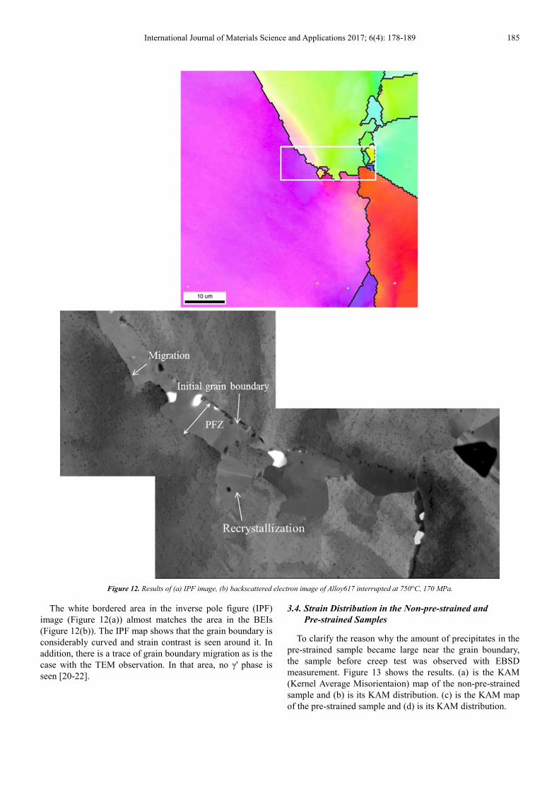
Figure 13. Comparison of KAM of virgin alloy with pre-strained alloy (a) KAM map of virgin alloy, (b) KAM distribution of virgin alloy, (c) KAM map of
pre-strained alloy, (d) KAM distribution of pre-strained alloy.
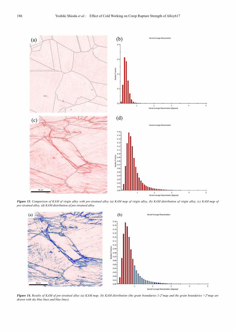
Figure 14. Results of KAM of pre-strained alloy (a) KAM map, (b) KAM distribution (the grain boundaries 1-2°map and the grain boundaries >2°map are
drawn with sky blue lines and blue lines).

International Journal of Materials Science and Applications 2017; 6(4): 178-189 187
It means in Figure 13 that as the red color becomes darker
on the KAM map, the local misorientation (i.e. dislocation
density) is larger. There are no regions with large KAM
values in the non-pre-strained sample. On the other hand, in
the pre-strained sample, regions with large KAM values are
locally seen near the grain boundaries. These are also seen in
the KAM distributions in Figures 13(b) and (d). In the
non-pre-strained sample, the peak is around 0.3° and at the
KAM values of 1° or more, whereas in the pre-strained
sample, the ratio of the KAM values of 1° or more is larger
and the ratio of 2 to 3° or more is also larger than in the
non-pre-strained sample. In order to make clear the regions
where the KAM values are 1° or more (i.e. sections with
large dislocation density) in the pre-strained sample, the
sections with KAM values of 1 to 2° are shown in sky blue
color and the regions with 3° or more are shown in blue color
in Figure 14.
It is found in Figure 14 that most of the regions with KAM
values of 3° or more exist near the grain boundaries. It is
considered that many dislocations introduced by the
pre-strain have accumulated near grain boundaries. These
facts indicate that a large amount of precipitates near grain
boundaries observed in the pre-strained sample is due to the
precipitation on the dislocation accumulated near the grain
boundaries. It has been reported that dislocations introduced
by cold working in Ni base alloys and austenitic steel become
precipitation sites and they accelerate precipitation [22, 23].
In addition, it has been reported that an increase in
precipitates near grain boundaries improves the creep rupture
strength [24, 25]. It is considered that the precipitates near
grain boundaries in the pre-strained sample play an important
role to reduce grain boundary migration and thereby prevent
the formation of zigzag grain boundaries and reduce the
formation of weak conditions such as PFZ and
recrystallization, which results in an improved creep strength.
Figure 15 shows the IPF maps of the samples ruptured at
750°C under 170 MPa. (a) (non-pre-strained sample) and (b)
(pre-strained sample) show that recrystallization have
developed at the grain boundaries and at crack initiation sites
for both samples.
Figure 15. IPF images with EBSD of Alloy617 ruptured at 750°C, 170 MPa (a) Virgin, (b) pre-strain at 30%.
As mentioned in the section in 3.1, the rupture time of the
non-pre-strained sample is shorter than that of the
pre-strained sample. This fact is probably because many
recrystallization grains were formed at the grain boundaries,
as is seen Figure 15(a). In other words, weak conditions are
quickly formed in the non-pre-strained sample comparing to
the pre-strained sample.
3.5. Differences in Creep Deformation Behaviors Depending
on Stress
In the previous section, the reason why the creep rupture
strength of the pre-strained sample at low stress conditions is
higher than that of the non-pre-strained sample was explained.

188 Yoshiki Shioda et al.: Effect of Cold Working on Creep Rupture Strength of Alloy617
In this section, the threshold stress between the high stress
condition and the low stress condition is mentioned. It has
been reported that the threshold is consistent with the stress
at which instantaneous plastic strain occurs in creep test
when stress is applied (athermal yield stress) [26-28]. When
the test stress is equal to or higher than the threshold stress,
large plastic deformation occurs and many dislocations are
introduced, which work-hardens the test samples. It is
considered that these introduced dislocations affect creep
deformation behaviors and that the amount of the
dislocations varies whether the applied stress is higher or
lower than the threshold stress. In this study, the stress at
which instantaneous plastic strain occurred after application
of stress was determined from Figure 4. The threshold stress
for the non-pre-strained sample was approximately 300 MPa
at 700°C and 170 MPa or more at 750°C. In this research, all
creep tests at 700°C correspond to conditions greater than the
athermal yield stress. Therefore, the non-pre-strained sample
is possibly work-hardened when stress is applied, and hence
the creep strength becomes the same as that of the
pre-strained sample. Meanwhile, all the test stresses at 750°C
creep are equal to or lower than the threshold stress.
Therefore, the non-pre-strained samples are not
work-hardened when stress is applied and thereby the
microstructural difference is observed, as mentioned in 3.4.
As a result, the creep rupture time of the non-pre-strained
sample becomes shorter than that of the pre-strained sample.
From the above, it is considered that the dislocations
introduced before the creep deformation promotes
precipitation of γ' phase and M23C6 carbide near the grain
boundary and they delay formation of PFZ. Therefore, the
creep rupture strength of Alloy 617 increases due to
introduction of dislocations.
4. Conclusion
The effect of cold working on the creep rupture strength of
Alloy617 was investigated. The obtained results are as follows.
(1) At high stress conditions, the creep rupture time of the
non-pre-strained samples are similar to those of the
pre-strained samples. Meanwhile, at low stress conditions,
the creep rupture time of the pre-strained samples are longer
than those of the non-pre-strained samples. The threshold
stress is almost consistent with the stress at which
instantaneous strain in the non-pre-strained sample occurs.
(2) Both the transient creep rate and the minimum creep
rate of the pre-strained samples are smaller than those of the
non-pre-strained samples. The value of minimum creep rate
is smaller by approximately one order of magnitude. In
addition, it is found that applying pre-strain delays both the
time to reach the minimum creep rate and time at which
acceleration begins.
(3) Weak conditions such as PFZ and recrystallization
grains in the non-pre-strained sample are formed at an earlier
stage of creep compared to the pre-strained sample.
(4) The density of precipitates near the grain boundaries is
larger in the pre-strained sample than that in the non-pre-strained
sample. It is considered from this result that at low stress
conditions, the precipitates near the grain boundaries in the
pre-strained sample play an important role to pin the grain
boundaries and that they delay the formation of weak conditions
resulting in extension of the creep rupture time. However, at
high stress conditions, the non-pre-strained sample is possibly
work-hardened when stress is applied and this creep strength
becomes same as that of the pre-strained sample.
References
[1] H. Umaki, I. Kajigaya, T. Kunihiro, T. Totsuka, M. Nakashiro and T. Kume, Application of Large Diameter Seam Welded Pipes and Header of Super 9Cr Steel for 700MW Coal-Fired Boiler with 593°C Reheat Steam Temperature, Ishikawajima-Harima Engineering Review. 31 (1991) 339-345 (in Japanese).
[2] S. J. Patel, J. J. DeBarbadillo, B. A. Baker, R. D. Gollihue, Nickel Base Superalloys for Next Generation Coal Fired AUSC Power Plants, Procedia Engineering. 55 (2013) 246-252.
[3] R. Viswanathan, J. F. Henry, J. Tanzosh, G. Stanko, J. Shingledecker, B. Vitalis and R. Purgert, U.S. Program on Materials Technology for Ultra-Supercritical Coal Power Plants, Journal of Materials Engineering and Performance. 14, (2005) 281-292.
[4] J. P. Shingledecker, Testing and Analysis of Full-Scale Creep-Rupture Experiments on Inconel Alloy 740 Cold-Formed Tubing, Journal of Materials Engineering and Performance. 22 (2013) 454-462.
[5] M. Fukuda, Advanced USC, Journal of the Thermal and Nuclear Power. 62 (2011) 731-740 (in Japanese).
[6] F. Abe, Research and Development of Heat-Resistant Materials for Advanced USC Power Plants with Steam Temperatures of 700°C and Above, Engineering. 1 (2015) 211-224.
[7] J. Klower, R. U. Husemann, M. Bader, Development of Nickel Alloys Based on Alloy617 for Components in 700°C Power Plants, Procedia Engineering. 55 (2013) 226-231.
[8] K. Kubusiro, K. Nomura, H. Nakagawa, Y. Ohkuma and K. Muroki, Development of fabrication technology for the A-USC boiler, Proceedings of the International Conference on Power Engineering-15 (2015).
[9] W. Ren and R. Swimdeman, A Review Paper on Aging Effects in Alloy 617 for Gen IV Nuclear Reactor Applications, Transactions of the ASME. 131 (2009).
[10] H. Nickel, Characterization of metallic and ceramic high temperature materials for energy systems by means of atomic spectroscopy, Pure & Appl. Chem. 65 (1993) 2481-2500.
[11] Q. Wu, H. Song, R. W. Swindeman, J. P. Shingledecker, and V. K. Vasudevan, Microstructure of Long-Term Aged IN617 Ni-Base Superalloy, Metallurgical and Materials Transactions A. 39A (2008) 2569-2585.
[12] E. Gariboldi, M. Cabibbob, S. Spigarellib and D. Ripamonti, Investigation on precipitation phenomena of Ni-22Cr-12Co-9Mo alloy aged and crept at high temperature, International Journal of Pressure Vessels and Piping. 85 (2008) 63-71.

International Journal of Materials Science and Applications 2017; 6(4): 178-189 189
[13] K. Okada, Y. Semba, S. Ishikawa and M. Yoshizawa, Effect of cold working on creep properties of a 23Cr-45Ni-7W alloy, Proceedings of the 163rd ISIJ Meeting. 25 (2012) 405 (in Japanese).
[14] K. Kubushiro, Y. Shioda and K. Nomura, Effect of Pre-strain on the Creep Strength of Ni-Based Alloys for A-USC Boilers, Trans Indian Inst Met. DOI 10.1007/s12666-016-0919-3.
[15] A. Iseda, M. Kubota, Y. Hayase, S. Yamamoto and K. Yoshikawa, Application and Properties of Modified 9Cr-1Mo Steel Tubes and Pipe for Fossil-fired Power Plants, The Sumitomo Search. 36 (1988) (in Japanese).
[16] S. Caminada, G. Cumino, L. Cipolla and A. Di Gianfrancesco, Cold bending of advanced ferritic steels: ASTM grades T23, T91, T92, International Journal of Pressure Vessels and Piping. 86 (2009) 853-861.
[17] Y. Kurata and H. Nakajima, Creep properties of 20% cold-worked Hastelloy XR, Journal of Nuclear Materials. 228 (1996) 176-183.
[18] K. Mino, A. Ohtomo and Y. Saiga, Effect of Grain Boundary Migration and Recrystallization on the Creep Strength of Inconel 617, Tetsu-to-Hagane. 63 (1977) 106-114 (in Japanese).
[19] S. Chomette, J. M. Gentzbittel and B. Viguier, Creep behaviour of as received, aged and cold worked INCONEL 617 at 850°C and 950°C, Journal of Nuclear Materials 399 (2010) 266–274.
[20] M. Yonemura, H. Semba and M. Igarashi, Development of Microstructural Damage in Ni-Based Alloys During Creep, Metallurgical and Materials Transactions A. 47A (2016) 1898-1905.
[21] Y. Wu, M. Zhang, X. Xie, F. Lin and S. Zhao, Dynamic recrystallization of a new nickel-based alloy for 700°C A-USC power plant applications with different initial states: as-homogenized and as-forged, Materials Science & Engineering A. 662 (2016) 283-295.
[22] A. Porter and B. Ralph, The recrystallization of nickel-base superalloys, Journal of material science. 16 (1981) 707-713.
[23] T. Nakazawa and H. Abo, The Effects of Some Factors on the Creep Behavior of Type 304 Stainless Steel, Tetsu-to-Hagane. 63 (1977) 82-91 (in Japanese).
[24] A. M. Elbatahgy, T. Matsuo and M. Kikuchi, Grain Boundary Precipitation Strengthening due to γ' Phase in High Temperature Creep of a Ni-base Superalloy, Tetsu-to-Hagane. 76 (1990) 125-132 (in Japanese).
[25] Y. Kondo, A. Ishizaki and J. Namekata, Effect of Carbide Precipitation Formed on Dislocations along Grain Boundaries on High Temperature Creep Resistance of a Ni-30Cr Alloy, Tetsu-to-Hagane. 76 (1990) 147-154 (in Japanese).
[26] K. Kimura, K. Sawada and H. Kushima, Long-Term Creep Strength Property of Advanced Ferritic Creep Resistant Steels, Proceedings of 6th Int Conf on Advanced in Materials Technology for Fossil Power Plants. (2010) 732-751.
[27] K. Sawada, K. Kubo and K. Kimura, Evaluation of Microstructural Factors of High Chromium Ferritic Steel Based on Analysis of Anelasticity Behavior at High Temperature, Tetsu-to-Hagane. 90 (2004) 835-840 (in Japanese).
[28] K. Maruyama, K. Sawada, J. Koike, H. Sato and K. Yagi, Examination of deformation mechanism maps in 2.25Cr-1Mo steel by creep tests at strain rates of 10-11 to 10-6 S-1, Materials Science and Engineering A. 224 (1997) 166-172.