EFFECT OF COATING MATERIALS AND MIXTURE …etd.lib.metu.edu.tr/upload/12614214/index.pdf · Table...
78
EFFECT OF COATING MATERIALS AND MIXTURE CONSTITUENTS ON THE PERMEABILITY OF CONCRETE A THESIS SUBMITTED TO THE GRADUATE SCHOOL OF NATURAL AND APPLIED SCIENCES OF MIDDLE EAST TECHNICAL UNIVERSITY BY AHMET VELĠ TEKĠN IN PARTIAL FULFILLMENT OF THE REQUIREMENTS FOR THE DEGREE OF MASTER OF SCIENCE IN CIVIL ENGINEERING FEBRUARY 2012
Transcript of EFFECT OF COATING MATERIALS AND MIXTURE …etd.lib.metu.edu.tr/upload/12614214/index.pdf · Table...

EFFECT OF COATING MATERIALS AND MIXTURE CONSTITUENTS
ON THE PERMEABILITY OF CONCRETE
A THESIS SUBMITTED TO
THE GRADUATE SCHOOL OF NATURAL AND APPLIED SCIENCES
OF
MIDDLE EAST TECHNICAL UNIVERSITY
BY
AHMET VELĠ TEKĠN
IN PARTIAL FULFILLMENT OF THE REQUIREMENTS
FOR
THE DEGREE OF MASTER OF SCIENCE
IN
CIVIL ENGINEERING
FEBRUARY 2012
Approval of the thesis:
EFFECT OF COATING MATERIALS AND MIXTURE
CONSTITUENTS ON THE PERMEABILITY OF
CONCRETE
submitted by AHMET VELİ TEKİN in partial fulfillment of the
requirements for the degree of Master of Science in Civil Engineering
Department, Middle East Technical University by,
Prof. Dr. Canan Özgen ____________________
Dean, Graduate School of Natural and Applied Sciences
Prof. Dr. Güney Özcebe ____________________
Head of Department, Civil Engineering
Asst. Prof. Dr. Sinan Turhan Erdoğan ____________________
Supervisor, Civil Engineering Dept., METU
Examining Committee Members:
Prof. Dr. Mustafa Tokyay ____________________
Civil Engineering Dept., METU
Asst. Prof. Dr. Sinan Turhan Erdoğan ____________________
Civil Engineering Dept., METU
Prof. Dr. Çetin HoĢten ____________________
Mining Engineering Dept., METU
Assoc. Prof. Dr. Lütfullah Turanlı ____________________
Civil Engineering Dept., METU
Assoc. Prof. Dr. Ġsmail Özgür Yaman ____________________
Civil Engineering Dept., METU
Date: February 8, 2012

iii
I hereby declare that all information in this document has been
obtained and presented in accordance with academic rules and
ethical conduct. I also declare that, as required by these rules and
conduct, I have fully cited and referenced all material and results
that are not original to this work.
Name, Last Name : AHMET VELĠ TEKĠN
Signature :

iv
ABSTRACT
EFFECT OF COATING MATERIALS AND MIXTURE
CONSTITUENTS ON THE PERMEABILITY OF CONCRETE
Tekin, Ahmet Veli
M.S., Department of Civil Engineering
Supervisor: Asst. Prof Dr. Sinan Turhan Erdoğan
February 2012, 62 pages
The improvement in the impermeability of concrete was studied using different
methods. The main aim was to investigate impermeability improvement of
concrete and to compare these methods. Two different methods were examined
to investigate and compare impermeability and strength improvement of
concrete by using two different sets of concrete specimens. These methods
included the application of coating materials to concrete and the production of
concrete using different constituent amounts and types. The first set of concrete
specimens was prepared by applying two different coating materials (a coating
material including both powder and liquid components; and a coating material
including only a liquid component) on reference concrete specimens
separately. The second set of concrete specimens was prepared using different
proportions of concrete constituents such as cement, water, steel and plastic
fibers, mineral and chemical concrete admixtures.
Various tests were conducted on both sets of concrete specimens in order to
compare the permeability of concrete specimens. However, some of these tests

v
were not applied on all of the specimens because of test and material
specifications. The tests were used to evaluate compressive strength, water
absorption, chloride ion penetration and depth of water penetration under
pressure. These test methods were carried out on concrete cube specimens and
concrete cores taken from those specimens according to the relevant standards.
It was found that the permeability of the concrete specimens decreased
significantly when the coating material which was composed of the
combination of powder and liquid components was applied on concrete
specimens. However, permeability did not decrease significantly for concrete
specimens coated with the coating material composed of only a liquid
component. Significant improvement in the impermeability of the concrete
specimens was observed when the amount of cement was increased, the water-
to-cement ratio was decreased, mineral admixtures (silica fume and fly ash)
and plasticizers were used. This improvement was associated with
densification of the concrete microstructure and reduction in capillary pores as
a result of pozzolanic reaction and due to reduction in water-to-cement ratio.
Coating materials were determined to be effective for concretes with high
permeability prior to coating whereas their effect was less significant for
lower-initial permeability concretes. Moreover, the effect of coating materials
on permeability differed depending on their chemical compositions. The effect
of using steel fibers and plastic fibers for the improvement of concrete
impermeability was found to be insignificant.
Keywords: Concrete, Permeability, Coating Materials, Pozzolanic Reactions

vi
ÖZ
KAPLAMA MALZEMELERĠ VE KARIġIM
BĠLEġENLERĠNĠN BETON GEÇĠRĠMLĠLĠĞĠ ÜZERĠNDEKĠ
ETKĠSĠ
Tekin, Ahmet Veli
Yüksek Lisans, ĠnĢaat Mühendisliği Bölümü
Tez Yöneticisi: Yrd. Doç. Dr. Sinan Turhan Erdoğan
ġubat 2012, 62 sayfa
Farklı yöntemler kullanılarak beton geçirimsizliğinin geliĢtirilmesine çalıĢıldı.
Temel amaç beton için geçirimsizlik geliĢtirilmesini incelemek ve bu
yöntemleri karĢılaĢtırmaktı. Beton geçirimsizliği ve dayanımı geliĢimini
incelemek ve karĢılaĢtırmak için iki farklı yöntem iki farklı beton numune seti
vasıtasıyla araĢtırıldı. Bu yöntemler, betona kaplama malzemesi uygulanmasını
ve farklı beton bileĢen miktarları ve çeĢitleri kullanarak beton üretimini içerdi.
Ġlk beton numunesi seti referans beton numuneleri üzerine ayrı ayrı iki farklı
kaplama malzemesi (toz ve sıvı bileĢen kombinasyonu içeren kaplama
malzemesi; ve sadece sıvı bileĢen içeren kaplama malzemesi) uygulanarak
üretildi. Ġkinci beton numunesi seti, çimento, su, çelik ve plastik fiber, kimyasal
ve mineral katkıların farklı oranlada kullanılmasıyla hazırlandı.
Beton numunelerinin geçirimliliğini karĢılaĢtırmak için her iki beton numunesi
seti üzerinde farklı deneyler uygulandı. Bununla birlikte, bu deneylerin bir
kısmı deney ve numune özellikleri nedeniyle tüm numuneler üzerinde
uygulanmadı. Bu deneyler basınç dayanımını, su emmesini, klor iyonu

vii
penetrasyonunu ve basınç altında su iĢleme derinliğini değerlendirmek için
kullanıldı. Bu deney yöntemleri, beton küp numuneleri ve bu numunelerden
alınan karot numuneler üzerinde ilgili deney standartlarına göre uygulandı.
Beton numuneleri üzerine toz ve sıvı bileĢen kombinasyonuna sahip kaplama
malzemesi uygulandığında bu numunelerin geçirimliliğinin önemli miktarda
azaldığı saptandı. Bununla birlikte, sadece sıvı bileĢen içeren kaplama
malzemesi ile kaplanmıĢ beton numuneleri için beton geçirimliliğinin önemli
miktarda azalmadığı saptandı. Çimento miktarı arttırılarak, su/çimento oranı
düĢürülerek, mineral katkılar (silis dumanı ve uçucu kül) ve akıĢkanlaĢtırıcı
kullanılarak üretilen beton numunelerinin beton geçirimsizliğinde önemli bir
geliĢme olduğu saptandı. Bu geliĢme puzolanik reaksiyonlar ve su/çimento
oranındaki azalma sonucunda oluĢan beton mikroyapısı sıkılaĢtırması ve
kapiller boĢluklardaki azalma ile iliĢkilendirildi. Kaplama malzemelerinin, ilk
geçirimliliği düĢük olan betonlar için az önemli olmakla birlikte, geçirimliliği
yüksek betonlar için etkili olduğu belirlendi. Buna ek olarak, kaplama
malzemelerinin geçirimlilik üzerindeki etkilerinin kimyasal özelliklerine göre
değiĢtiği belirlendi. Beton üretiminde çelik ve plastik fiberlerin kullanılmasının
beton geçirimsizliği geliĢtirilmesi üzerindeki etkisinin çok önemli olmadığı
saptandı.
Anahtar Kelimeler: Beton, Geçirimlilik, Kaplama Malzemeleri, Puzolanik
Reaksiyonlar.

viii
To My Family...

ix
ACKNOWLEDGMENTS
I would first like to thank my supervisor, Asst. Prof. Dr. Sinan Turhan
Erdoğan, for his motivating support and strong guidance.
I also wish to thank Prof. Dr. Mustafa Tokyay, Assoc. Prof. Dr. Ġsmail Özgür
Yaman, Prof. Dr. Turhan Erdoğan, Assoc. Prof. Dr. Lütfullah Turanlı and Prof.
Dr. Çetin HoĢten for their support throughout my B.S. and M.S. studies. I
would like to present my respect and appreciation to my family for their
enduring contributions and encouragement during my studies and throughout
my life.
I would like to acknowledge the continuous support of Mr. M. Fatih
Kocabeyler, Head of Technical Research and Quality Control Department
(Teknik AraĢtırma ve Kalite Kontrol Dairesi BaĢkanlığı [TAKK]) at the
General Directorate of State Hydraulic Works (Devlet Su ĠĢleri Genel
Müdürlüğü [DSĠ]). I also would like to thank Mr. Ergin Tunç, Mr. Aydın
Sağlık, Mr. Hüseyin Kul my friends and the laboratory staff of the concrete
laboratory at TAKK (DSĠ) for their support for my study.

x
TABLE OF CONTENTS
ABSTRACT ..................................................................................................... IV
ÖZ ..................................................................................................................... VI
ACKNOWLEDGMENTS ................................................................................ IX
TABLE OF CONTENTS ................................................................................... X
LIST OF TABLES ......................................................................................... XIII
LIST OF FIGURES ......................................................................................... XV
CHAPTERS
1 INTRODUCTION ...................................................................................... 1
1.1 Background ............................................................................................. 1
1.2 Aim and Objectives ................................................................................. 2
2 LITERATURE REVIEW ........................................................................... 4
2.1 Durability and Permeability of Concrete ................................................. 4
2.2 Hydration of Portland Cement ................................................................ 5
2.2.1 Microstructure of Hydrated Cement Pastes ......................................... 5
2.3 Causes of Inadequate Durability of Concrete .......................................... 8
2.3.1 Transport of Fluids in Concrete ........................................................... 9
2.3.2 Porosity and Permeability in Concrete .............................................. 11
2.4 Deterioration Mechanism of Concrete .................................................. 13

xi
2.5 Methods to Mitigate Deterioration of Concrete .................................... 15
2.5.1 Coating of Concrete ........................................................................... 15
2.5.2 Effects of Mineral Admixtures on the Permeability of Concrete ...... 18
2.6 Determination of Chloride Penetrability into Concrete ........................ 19
3 EXPERIMENTAL PHASE ...................................................................... 20
3.1 Preparation of Concrete Specimens ...................................................... 21
3.2 Concrete Constituent Materials ............................................................. 22
3.2.1 Cement ............................................................................................... 22
3.2.2 Aggregates ......................................................................................... 23
3.2.3 Water .................................................................................................. 23
3.2.4 Fly Ash ............................................................................................... 23
3.2.5 Silica Fume ........................................................................................ 24
3.2.6 Water-reducing concrete admixtures ................................................. 25
3.2.7 Air entraining admixture .................................................................... 25
3.2.8 Steel Fibres ........................................................................................ 25
3.2.9 Plastic Fibres ...................................................................................... 26
3.3 Coating Materials Applied to Concrete Specimens .............................. 26
3.3.1 Coating Material 1 ............................................................................. 26
3.3.2 Coating Material 2 ............................................................................. 27
3.4 Tests Performed ..................................................................................... 28
3.4.1 Concrete Compressive Strength Tests ............................................... 31
3.4.2 Concrete Water Absorption Tests ...................................................... 31
3.4.3 Chloride Ion Penetration Tests .......................................................... 33
3.4.4 Depth of Penetration of Water under Pressure Tests ......................... 34
4 RESULTS AND DISCUSSION ............................................................... 36
4.1 Concrete Compressive Strength Test Results ....................................... 36
4.2 Concrete Water Absorption Test Results .............................................. 38
4.3 Chloride Ion Penetration Test Results ................................................... 39
4.4 Depth of Penetration of Water under Pressure Test Results ................. 42

xii
4.5 Discussion of Test Results .................................................................... 44
5 CONCLUSION AND RECOMMENDATIONS...................................... 47
5.1 Conclusion ............................................................................................. 47
5.2 Recommendations ................................................................................. 49
REFERENCES ................................................................................................. 50
APPENDICES
A. COMPRESSIVE STRENGTH TEST RESULTS .................................... 54
B. WATER ABSORPTION TEST RESULTS ............................................. 56
C. RAPID CHLORIDE ION PENETRATION TEST RESULTS ................ 58
D. DEPTH OF PENETRATION TEST RESULTS ...................................... 61
xiii
LIST OF TABLES
TABLES
Table 2.1 Requirements for special exposure conditions (ACI 318R) ............... 5
Table 2.2 Hydration reactions for two calcium silicates (Mindess et al. 2003) . 5
Table 2.3 Sequence of hydration of the calcium silicates (Mindess et al. 2003).
............................................................................................................................ 6
Table 2.4 Main compounds of Portland cement (Neville, 2000) ....................... 6
Table 2.5 Usual composition limits of Portland cement (Neville, 2000) ........... 7
Table 2.6 Pore size classification in hydrated cement paste (Mindess et al.
2003) ................................................................................................................... 7
Table 2.7 Criteria for HPC (High Performance Concrete) (SHRP, 1993) ....... 10
Table 2.8 Causes of distress and deterioration of concrete (EM-1110-2-2002)13
Table 2.9 Factors influencing chemical attack on concrete (ACI 201.2R) ...... 14
Table 2.10 Summary of surface treatments (ACI 546R) .................................. 16
Table 2.11 Protective barrier systems-general categories (ACI 515.1R cited in
ACI 201.2R) ..................................................................................................... 17
Table 3.1 Concrete constituents ....................................................................... 21
Table 3.2 Composition of Cem I 42.5 N Portland cement (ġahin, 2012) ........ 22
Table 3.3 Aggregate properties (DSĠ Quality Control Laboratories, 2009) ..... 23
Table 3.4 Fly ash constituent amounts (Özel, 2012) ........................................ 23
Table 3.5 Silica fume constituent amounts (Sarıcaoğlu, 2012) ........................ 24
Table 3.6 Steel fiber properties (Bekaert, 2012) .............................................. 25
Table 3.7 Plastic fiber properties (Forta, 2012) ................................................ 26
Table 3.8 Tests conducted on the different specimen sets ............................... 29

xiv
Table 4.1 Concrete compressive strength test results (cube specimens of
150x150x150 mm) and fresh concrete properties ............................................ 36
Table 4.2 Water absorption amounts for different coating materials and
different concrete types .................................................................................... 38
Table 4.3 Chloride ion penetration test results for the two coating materials and
different concrete types .................................................................................... 40
Table 4.4 Recommendation for assessing chloride ion (ASTM C 1202) ........ 41
Table 4.5 Results of depth of water penetration under pressure tests .............. 42
Table A.1 Concrete compressive strength values ............................................ 54
Table B.1 Water absorption test results for reference concrete specimens and
reference concrete specimens coated with two different coating materials ..... 56
Table B.2 Water absorption results for 4 different types of concrete specimen
types and coating material 2. ............................................................................ 57
Table C.1 Chloride ion penetration test results for reference concretes and
coating materials applied ref. concretes ........................................................... 58
Table C.2 Chloride ion penetration test results for different types of concretes
.......................................................................................................................... 60
Table D.1 Depth of penetration of water under pressure for ref. concrete
specimen and coating material applied ref. concrete specimen ....................... 61
Table D.2 Depth of penetration under pressure test results for 4 different types
of concrete specimens ...................................................................................... 62

xv
LIST OF FIGURES
FIGURES
Figure 2.1 Portland cement a) Unhydrated particles-magnification 2000x; b)
Multiple particles of partially hydrated-magnification 4000x; c) Single particle
of hydrated cement- magnification 11000x) (SEM photos by E. Soroos and K.
Hover cited in Hover, 2011) ............................................................................. 11
Figure 2.2 Relations among w/cm, average 28-day compressive strength and
permeability (ACI 318 Building code requirements and USBR data cited in
Hover, 2011). .................................................................................................... 12
Figure 3.1 a) Preparation of coating material 1; b) application of coating
material 1 on concrete cores ............................................................................. 27
Figure 3.2 Application of coating material 2 to concrete cores ....................... 28
Figure 3.3 a) Concrete cube curing; b) Coring; c) Concrete cores; d) Cutting of
cores .................................................................................................................. 30
Figure 3.4 a) Application of coating material 1; b) Water absorption tests ..... 32
Figure 3.5 a) Conditioning of cores; b) Placement of concrete cores into test
cells; c) Placement of solutions; d) Application of electrical potential for
chloride ion penetration test phases .................................................................. 34
Figure 3.6 a) Application of water pressure to cube specimens; b) Wetted-front
after water penetration test ............................................................................... 35
Figure 4.1 Concrete compressive strength development trends for the different
concrete mixtures ............................................................................................. 37
Figure 4.2 a) Water absorption amounts for the different mixtures; b) Water
absorption comparisons .................................................................................... 38

xvi
Figure 4.3 Relation between compressive strength and water absorption ....... 39
Figure 4.4 a) Results for chloride ion penetration tests for the two coating
materials and different concrete types; b) Comparisons of the results with
reference concrete ............................................................................................. 40
Figure 4.5 Compressive strength and chloride ion penetration relation ........... 42
Figure 4.6 a) Results for depth of water penetration values under pressure; b)
Comparisons of the results with reference concrete ......................................... 43
Figure 4.7 Compressive strength and water penetration depth relation ........... 43
Figure A.1 Concrete compressive strength values for different concrete types
(150x150x150 mm) .......................................................................................... 55
Figure B.1 Water absorption comparisons for reference concretes and reference
concrete specimens coated with two different coating materials applied ........ 56
Figure B.2 Water absorption amounts for different concrete types ................. 57
Figure C.1 Chloride ion penetration values for Ref.C. and coating materials . 59
Figure C.2 Chloride penetration average values .............................................. 59
Figure C.3 Chloride ion penetration values for different concretes ................. 60
Figure D.1 Water penetration depth under pressure test results for ref. concrete
and coating material 1 applied ref. concrete ..................................................... 61
Figure D.2 Water penetration depth test results for different concrete types ... 62

1
CHAPTER 1
1 INTRODUCTION
1.1 Background
“Concrete is a composite material that consists essentially of a binding medium
within which are embedded particles or fragments of aggregate, usually a
combination of fine aggregate and coarse aggregate”. “In Portland-cement
concrete, the binder is a mixture of Portland cement and water, with or without
admixtures” (ACI 116R).
The durability of concrete is considered to be an important parameter of the
service life of concrete. That is, in addition to compressive strength, durability
should be taken into account in the concrete production process. The
continuation of their intended functions is essential for concrete structures.
Namely, these structures should maintain their required strength and
serviceability during the specified service life. In other words, concrete must be
able to withstand the inner and outer deterioration processes. This property for
concrete is named “durability of concrete” (Neville, 2000). ACI Committee
201 states durability of concrete as its resistance to weathering mechanisms,
abrasion, chemical mechanisms and to any deterioration mechanism. Durability
of construction materials is important because of their positive implications for
socioeconomic and ecological prospects (Mehta, 1986). The durability of
concrete becomes more important especially for concrete structures which are
built in harsh environments where there is risk of chemical or physical attack.

2
The durability of concrete is mostly considered to be related with the
permeability of concrete which refers to the ease of fluid entrance into and
movement through concrete (Neville, 2000). The improvement of the
impermeability of concrete is required to prevent alkali-silica reaction as well
as other deterioration mechanisms. In this way, improving the impermeability
of concrete in the concrete production phase by adjusting concrete constituent
amounts and improving the impermeability of concrete structures after they are
built by applying a coating material to hardening concrete offer two
alternatives to resist deterioration of concrete. As a result, research is needed to
compare impermeability improvement methods.
1.2 Aim and Objectives
Objectives of the study were:
a) To compare methods to reduce water permeability of concrete
including application of two different coating materials on hardened
concrete and changing concrete mixture constituents and types.
b) To investigate the effectiveness of coating materials in reducing
permeability for concretes with changing concrete constituents.
c) To search for the correlation between concrete permeability and
compressive strength.

3
Two different sets of concrete specimens were prepared in the laboratory.
a) The first set of specimens was prepared by applying one of two
different coating materials (combination of powder and liquid; and
liquid-only) on to hardened concrete specimens.
b) The second set of concrete specimens was produced by changing the
concrete constituents which consisted mainly of changing the water-to-
cementitious material ratio and adding mineral admixtures (silica fume
and fly ash).
In the chapters of the study following items were explained:
In Chapter 2, a review of literature on concrete durability and concrete
permeability is presented.
In Chapter 3, experimental phases of the research are explained.
In Chapter 4, results of the concrete permeability tests and discussions of these
results are given.
In Chapter 5, conclusions derived from the findings of the study are provided.

4
CHAPTER 2
2 LITERATURE REVIEW
2.1 Durability and Permeability of Concrete
Durability is the capacity of concrete to resist chemical attack, weathering
action, abrasion and service conditions. It is a complex issue and degradation
of concrete can involve some mechanisms related with transport of substances
into and out of concrete and their impacts on the concrete (ACI 116R).
Concrete becomes vulnerable to various exposures if some precautions are not
taken. Three major components of reinforced concrete are aggregate, paste, and
steel reinforcement and their adverse performance can lead to deterioration of
concrete. W/C is considered as the single parameter that has the largest impact
on durability characteristics of concrete. Decrease in w/c results in decrease in
porosity of the paste making concrete less permeable. Requirements of
concrete for use in special conditions are given in Table 2.1. The permeability
of concrete is an important parameter for durability as it controls entry of
moisture and aggressive chemicals. Moreover, low w/c increases the strength
of concrete and improves its resistance to cracking resulting from the internal
stresses (Mindess et al. 2003).

5
Table 2.1 Requirements for special exposure conditions (ACI 318R)
Exposure Condition
Maximum
cementitious material
ratio, by weight,
normal weight
concrete
Minimum fc,
normal weight
and lightweight
concrete, MPa
Concrete intended to have low permeability
when exposed to water 0.50 27.6
Concrete exposed to freezing and thawing in a
moist condition or to deicing chemicals 0.45 31.0
For corrosion protection of reinforcement in
concrete exposed to chlorides from deicing
chemicals, salt, salt water, brackish water, sea
water, or spray from these sources
0.40
34.5
2.2 Hydration of Portland Cement
Chemical and physical processes between cement and water are the main
determinants for the setting and hardening of concrete. The principal hydration
product is a calcium silicate hydrate, C-S-H (Mindess et al. 2003). Hydration
reactions of the two main calcium silicates in Portland cement are given in
Table 2.2.
Table 2.2 Hydration reactions for two calcium silicates (Mindess et al. 2003)
2 C3S + 11 H C3S2H8 + 3CH
Tricalcium silicate Water C-S-H Calcium hydroxide
2 C2S + 9H C3 S2H2 + CH
Dicalcium silicate Water C-S-H Calcium hydroxide
2.2.1 Microstructure of Hydrated Cement Pastes
Sequence of structure formation (see Table 2.3) as hydration proceeds is
important for the microstructural development of concrete. In that process,
water separating individual cement grains in the fluid paste is replaced with

6
solid hydration products forming a continuous matrix and binding residual
cement grains (Mindess et al. 2003).
Table 2.3 Sequence of hydration of the calcium silicates (Mindess et al. 2003).
Reaction Stage Kinetics of Reaction Chemical Process Relevance to
Concrete Properties
1-Initial hydrolysis Chemical control;
rapid
Initial hydrolysis;
dissolution of ions -
2-Induction Period Nucleation control;
slow
Continued
dissolution of ions
Determines initial set
3-Acceleration Chemical control;
rapid
Initial formation of
hydration products
Determines final set
and rate of initial
hardening
4-Deceleration Chemical and
diffusion control;
slow
Continued formation
of hydration of
products
Determines rate of
early strength gain
5-Steady state Diffusion control;
slow
Slow formation of
hydration products
Determines rate of
later strength gain
Porosity is an important component of the microstructure. An important aspect
of microstructural development is the decrease in porosity during hydration.
All the hydration products of the cement compounds have lower specific
gravities and larger specific volumes than the cement compounds themselves
(Mindess et al. 2003). Main compounds and usual composition for Portland
cement are given below in Table 2.4 and Table 2.5.
Table 2.4 Main compounds of Portland cement (Neville, 2000)
Name of Compound Oxide composition Abbreviation
Tricalcium silicate 3CaO.SiO2 C3S
Dicalcium silicate 2CaO.SiO2 C2S
Tricalcium aluminate 3CaO.Al2O3 C3A
Tetracalcium aluminoferrite 4CaO.Al2O3.Fe2O3 C4AF

7
Table 2.5 Usual composition limits of Portland cement (Neville, 2000)
Oxide Content (%)
CaO 60-67
SiO2 17-25
Al2O3 3-8
Fe2O3 0.5-6.0
MgO 0.5-4.0
Alkalis ( Na2O equivalent) 0.3-1.2
SO3 2.0-3.5
Pores in concrete are important for the permeability. Two of the different types
of pores are capillary pores and gel pores. Capillary pores are “remnants of
water-filled space between the partially hydrated cement grains”. The gel pores
are “intrinsic parts of the C-S-H”. The sizes of these pores are given in Table
2.6 (Mindess et al. 2003).
Table 2.6 Pore size classification in hydrated cement paste (Mindess et al.
2003)
Designation Diameter Description
Capillary Pores
10,000-50 nm (10-0.05 µm) Large capillaries
(macropores)
50-10 nm Medium capillaries
(large mesopores)
Gel Pores
10-2.5 nm
Small isolated
capillaries (small
mesopores)
2.5-0.5 nm Micropores
< 0.5 nm Interlayer spaces

8
The pore system within the bulk of the hardened cement paste and the interface
between the cement paste and the aggregate are important for permeability of
concrete. The permeability of concrete is affected by its porosity as well as
size, distribution, continuity, shape and tortuosity of the pores. Flow of water
through the capillary pores occurs more easily than through the much smaller
gel pores. That is, permeability of hardened paste is controlled by capillary
porosity in concrete (Neville, 2000).
2.3 Causes of Inadequate Durability of Concrete
Negative chemical and physical events that have negative effects on the
durability of concrete are decomposition of calcium hydroxide in concrete and
development of efflorescence on concrete surface, sulfate attack, sea water
attack, acid attack, carbonation, alkali-aggregate reaction, corrosion of
reinforcing steel in concrete, freezing-thawing effect and peeling of concrete
surface (Erdoğan, 2003).
Deterioration of concrete is a manifestation of inadequate durability of concrete
structures. This deterioration can be due either to external factors or internal
factors and those factors can be physical, chemical, or mechanical. The
mechanical ways of deterioration include impact, abrasion, erosion or
cavitation. The chemical mechanisms include the alkali-silica and alkali-
carbonate reactions. External chemical attacks are generally caused by the
action of aggressive ions (chlorides, sulfates etc.) and carbon dioxide.
Moreover a lot of natural and industrial liquids and gases lead to chemical
attacks. The physical causes of deterioration of concrete structures include
expansion of aggregate and of the hardened cement paste due to fluctuations in
temperature. An important cause of the damage is alternating freezing and
thawing of concrete and the associated action of de-icing salts. Except for the

9
mechanical damage to concrete structures, all the adverse effects on durability
involve the transport of fluids through the concrete. That’s why the transport of
fluids should be examined and analyzed in order to clarify the durability
concerns of concrete structures (Neville, 2000).
2.3.1 Transport of Fluids in Concrete
There are three fluids which are related with durability. These are water, pure
or carrying aggressive ions, carbon dioxide and oxygen. The movement of
these fluids can differ but their transportation in concrete depends mainly on
the structure of the hydrated cement paste. The durability of concrete mostly
depends on the ease with which fluids, both liquids and gases, can enter into,
and move through the concrete. This mechanism is defined as the permeability
of concrete. In other words, the permeability can be stated as flow through a
porous medium. Movement of some fluids through concrete can also take place
by diffusion and sorption. However “permeability” is used as a general term to
define the movement of fluids into and through concrete (Neville, 2000).
Transport properties of hardened concrete have an important role on the ingress
of potentially deleterious and harmful materials. The resistance of hardened
cement paste to chemical and physical impacts is related with the composition
and microstructural properties of the paste and also environmental conditions
around the concrete structures during both the fresh and hardened concrete
phases. That is, the transport properties of concrete (diffusity, permeability, and
sorptivity) are important factors (Young, 1988 cited in Arjunan, 2000).
Low permeability concrete possesses high strength and it is resistant to the
ingress of water and salt solutions. As chloride, oxygen and moisture reaches
steel easily, the corrosion of reinforcing steel takes place earlier and easier in

10
the case of porous surrounding concrete. That is, measurement of the
permeability of concrete contributes to detection of durability problems which
will in turn lead to timely and cost-effective protection of concrete structures
(Canadian Strategic Highway Research Program, 1995).
High performance concrete provides improved durability under severe
conditions, improved properties at early ages and enhanced mechanical
properties. These concretes may contain materials such as fly ash, silica fume,
ground, granulated slags, fibers and chemical admixtures. Service life will be
increased and life-cost may be reduced with higher durability of concretes
(Strategic Highway Research Program, 1993). Criteria for high performance
concrete are given in Table 2.7.
Table 2.7 Criteria for HPC (High Performance Concrete) (SHRP, 1993)
Category of HPC
Minimum
Compressive
Strength
Maximum
Water/Cement
Ratio
Minimum Frost
Durability Factor
Very early strength (VES)
Option A (with Type III
cement)
14 MPa in 6
hours 0.40 80 %
Option B (with PBC-XT
cement)
17.5 MPa in 4
hours 0.29 80 %
High early strength (HES)
(with Type III cement)
35 MPa in 24
hours 0.35 80 %
Very high strength (VHS)
(with Type I cement)
70 MPa in 28
days 0.35 80 %

11
2.3.2 Porosity and Permeability in Concrete
Porosity is the proportion of the total volume of concrete occupied by pores. In
the case of high porosity and interconnected pores, permeability of concrete
increases and transport of fluids becomes easy (Neville, 2000). Concrete
behavior is closely related with water which is needed for hydration but at the
same time occupies space in the concrete. Hydration of Portland cement is
shown at different size scales in Figure 2.1. Porosity of the hardened cement
paste is an important parameter affecting concrete strength and durability.
Filling degree of void spaces between and among the cement grains by the
hydration products mostly determines this porosity property (Hover, 2011).
a) b) c)
Figure 2.1 Portland cement a) Unhydrated particles-magnification 2000x; b)
Multiple particles of partially hydrated-magnification 4000x; c) Single particle
of hydrated cement- magnification 11000x) (SEM photos by E. Soroos and K.
Hover cited in Hover, 2011)
Hydration products and “degree of hydration” and pore space volume to be
filled are important for the permeability of concrete. On the other hand, higher
w/c means more water is available to maintain hydration but at the same time
inter-particle pore space will be greater which will require high degree of
hydration. Thus, lower w/c needs to be provided for high performance

12
concrete. The higher the w/c is, the higher the permeability and the lower the
compressive strength (see Figure 2.2) (Hover, 2011).
Figure 2.2 Relations among w/cm, average 28-day compressive strength and
permeability (ACI 318 Building code requirements and USBR data cited in
Hover, 2011).
The initial microstructural development of concrete is important for
minimizing harmful effects. The porosity and the pore structures of cement
paste are two major factors controlling the chemical resistance of concrete.
Porosity and permeability are, in turn, mainly controlled by water content of a
cement paste. It is also important to consider the development of the cement
paste structure beginning with the fresh state, mixing, placing, consolidation,
and through the curing period (Roy, 1986 cited in Arjunan, 2000).

13
2.4 Deterioration Mechanism of Concrete
Deterioration of concrete is a complex issue and it may have various reasons
(see Table 2.8). The resistance of concrete to attack depends on the specific
nature of chemical involved, the w/c of concrete, temperature of the aggressive
solution, the permeability of the concrete, consolidation degree of the concrete,
the type of the cement used in concrete, the degree of corrosion of the
reinforcing steel and the level of wetting-drying of the chemical on the
concrete (ACI 201.1R cited in EM 1110-2-2002, 2002).
Table 2.8 Causes of distress and deterioration of concrete (EM-1110-2-2002)
Accidental Loadings
Chemical Reactions
Acid attack
Aggressive water attack
Alkali-carbonate rock reaction
Alkali-silica reaction
Miscellaneous chemical attack
Sulfate attack
Construction Errors
Corrosion of Embedded Metals
Design Errors
Inadequate structural design
Poor design details
Erosion
Abrasion
Cavitation
Freezing and Thawing
Settlement and Movement
Shrinkage
Plastic
Drying
Temperature Changes
Internally generated
Externally generated
Fire
Weathering

14
Chemical reactions for concrete may be classified as external chemicals
attacking the concrete such as acid attack, aggressive water attack, sulfate
attack and internal chemical reactions between the constituents of the concrete
such as alkali-silica reaction and alkali-carbonate rock reactions (EM 1110-2-
2002). Factors that affect chemical attack on concrete structures are given in
Table 2.9.
Table 2.9 Factors influencing chemical attack on concrete (ACI 201.2R)
Factors that accelerate or
aggravate attack Factors that mitigate or delay attack
1. High porosity due to: 1. Dense concrete achieved by:
i. High water absorption i. Proper mixture proportioning
ii. Permeability ii. Reduced unit water content
iii. Voids iii. Increased cementitious material
content
iv. Air entrainment
v. Adequate consolidation
vi. Effective curing
2. Cracks and separations due
to:
2. Reduced tensile stress in
concrete by:
i. Stress concentrations i. Using tensile reinforcement of
adequate size, correctly located
ii. Thermal shock ii. Inclusion of pozzolan (to reduce
temperature rise)
iii. Provision of adequate contraction
joints
3. Leaching and liquid
penetration due to: 3. Structural Design
i. Flowing liquid i. To minimize areas of contact and
turbulence
ii. Ponding
ii. Provision of membranes and
protective-barrier system(s) to
reduce penetration
iii. Hydraulic pressure

15
2.5 Methods to Mitigate Deterioration of Concrete
The methods to produce impermeable concrete are using a finer cement, using
low water/cement ratio, using water free of deleterious compounds, using low-
permeability aggregates, using a good aggregate gradation, using additives
which reduce water/cement ratio or which prevent water entry into concrete
(Erdoğan, 2003).
2.5.1 Coating of Concrete
Coating of concrete, which is to apply material to a surface by brushing,
spraying etc. to protect and seal the substrate, is considered as a preventative
method against permeation of water and chemicals into concrete (ACI 116R).
Water penetration into concrete takes place because of hydrostatic pressure,
capillary action, wind-driven rain, moisture vapor pressure or any combination
of those. Leakage into structure, freezing-and-thawing deterioration and
corrosion of reinforcement in the concrete structures are augmented by water
penetration into concrete. That is, preventing water penetration should be
considered to establish a protection system for concrete structures (ACI 546R).
Surface treatment types and their properties are given in Table 2.10.

16
Table 2.10 Summary of surface treatments (ACI 546R)
Protective barriers (see Table 2.11) are used to protect concrete against
degradation by chemicals and to prevent concrete staining. First, they have to
resist permeation and diffusion of chemicals and they also have to be resistant
to cracking, swelling, and dissolution. Second, they have to possess sufficient
abrasion resistance during service. Third, the adhesive bond strength should be
at least equal to the tensile strength of the concrete (ACI 201.2R).
Types Generic classifications Installation Requirements Durability characteristics Performance characteristics
Boiled linseed oil
Sprayed
Approximately 10 °C or
above
Clean, dry and sound surface
Poor resistance to UV
radiation
Improves resistance to
freezing and thawing
Frequent applications
required
Darkens concrete slightly
Does not bridge cracks
Alkyl-alkoxy-silane
Siloxanes
Surface free of pretreatments
Sprayed, brushed, or rolled
Ventilation required
Improves resistance to
freezing and thawing
Reduces salt penetration
Reduces rate of corrosion
Improved resistance to water
absorption and reinforcement
corrosion
Does not bridge cracks
High-molecular-weight
methacrylate
Clean, dry and sound surface
Sprayed, brushed or rolled
Variable UV radiation
resistance
Prevents moisture from
penetrating cracks
Seal cracks
Coatings
Epoxy
Urethane or neoprane
membrane/epoxy top
coat system
Rubberized asphaltic top
coat system
Urethane
Membrane/urethane top
coat system
Clean, dry and sound surface
Sprayed, brushed, rolled, or
squeegeed
Approximately 10 °C and
above
Ventilation required
Level surface typically
required
Generally improves
resistance to freezing and
thawing
Fair to good abrasion
resistance
Variable UV radiation
resistance
Generally good resistance to
water absorption
Unknown resistance to
reinforcement corrosion
Bridges small cracks
Overlays
Concrete
Polymer concrete
Polymer-modified
concrete
Clean, sound and roughened
surface
Hand or machine applied
Generally above freezing
Ventilation may be required
Improves resistance to
freezing and thawing
Excellent abrasion
resistance
May add weight
Architectural finish is possible
Protects structural concrete
and reinforcement
May improve structural
capacity
Sealers
17
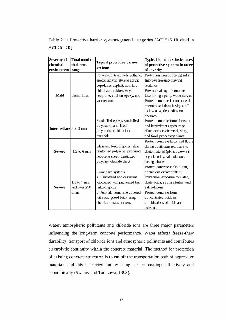
Table 2.11 Protective barrier systems-general categories (ACI 515.1R cited in
ACI 201.2R)
Water, atmospheric pollutants and chloride ions are three major parameters
influencing the long-term concrete performance. Water affects freeze-thaw
durability, transport of chloride ions and atmospheric pollutants and contributes
electrolytic continuity within the concrete material. The method for protection
of existing concrete structures is to cut off the transportation path of aggressive
materials and this is carried out by using surface coatings effectively and
economically (Swamy and Tanikawa, 1993).
Severity of
chemical
environment
Total nominal
thickness
range
Typical protective barrier
systems
Typical but not exclusive uses
of protective systems in order
of severity
Mild Under 1mm
Polyvinyl butryal, polyurethane,
epoxy, acrylic, styrene acrylic
copolymer asphalt, coal tar,
chlorinated rubber, vinyl,
neoprane, coal-tar epoxy, coal-
tar urethane
Protection against deicing salts
Improve freezing-thawing
resitance
Prevent staining of concrete
Use for high-purity water service
Protect concrete in contact with
chemical solutions having a pH
as low as 4, depending on
chemical
Intermediate 3 to 9 mm
Sand-filled epoxy, sand-filled
polyester, sand-filled
polyurethane, bituminous
materials
Protect concrete from abrasion
and intermittent exposure to
dilute acids in chemical, dairy,
and food-processing plants
Severe 1/2 to 6 mm
Glass-reinforced epoxy, glass
reinforced polyester, procured
neoprene sheet, plasticized
polyvinyl chloride sheet
Protect concrete tanks and floors
during continuous exposure to
dilute material (pH is below 3),
organic acids, salt solutions,
strong alkalies
Severe
1/2 to 7 mm
and over 250
6mm
Composite systems:
a) Sand-filled epoxy system
topcoated with pigmented but
unfilled epoxy
b) Asphalt membrane covered
with acid-proof brick using
chemical-resistant mortar
Protect concrete tanks during
continuous or intermittent
immersion, exposure to water,
dilute acids, strong alkalies, and
salt solutions
Protect concrete from
concentrated acids or
combinations of acids and
solvents.

18
2.5.2 Effects of Mineral Admixtures on the Permeability of
Concrete
Silica fume is mainly used because of its contribution to improve concrete
strength and concrete durability. Concrete durability improvement is achieved
by reducing aggressive fluid transport through the pore structure, reducing the
rate of chloride-ion ingress, improving resistance to deleterious effects of
alkali-silicate reaction and improving resistance to freezing and thawing.
Deterioration mechanism of concrete is mostly affected by transport properties
of materials, transport of gas, liquid and detrimental liquids. The improved
durability characteristics of silica fume concrete are mostly provided by the
low permeability of these concretes (ACI 234R).
Silica fume is used as a mineral admixture which results a denser pore structure
in concrete. This reduction in permeability and improvement of durability is
achieved by pore size refinement, Ca(OH)2 amount reduction and cement
paste-aggregate interfacial zone pore refinement. Pozzolanic reaction between
silica fume and calcium hydroxide leads to densification in interfacial
transition zone. Pozzolanic materials generally combine with hydrated calcium
hydroxide (Ca(OH)2) and form hydrated calcium silicate (C-S-H) which causes
strength development of hydrated cement paste (Song et al., 2010).
Silica fume usage in concrete leads to a reduction in water permeability
depending on silica fume dosage and mixture composition. The low
permeability of silica fume concrete is the main determinant for its improved
durability in the aggressive environment conditions (ACI 234R).

19
Concrete containing fly ash reaction products contribute to fill pores when the
concrete is properly cured. Thus concrete permeability to water and chemicals
is lowered (Manmohan and Mehta, 1981 cited in ACI 2322R).
Poon et al. (2006) carried out tests to determine and to compare compressive
strength, chloride penetrability and porosity of control specimens, metakaolin-
containing specimens and silica fume-containing specimens for 0.30 and 0.50
water/binder ratios, respectively. For both ratios, improvement was achieved
for all of the three parameters for metakaolin and silica fume-containing
concretes which were associated with strength and durability improvement due
to admixture additions.
2.6 Determination of Chloride Penetrability into Concrete
Corrosion of reinforcing steel because of chloride ingress is considered as an
important deterioration mechanism in reinforced concrete. Transport of
chloride ions is related with a few mechanisms including diffusion, migration
in an electric field, water permeation because of a pressure gradient and
absorption because of capillary action. Chloride ion transport through concrete
is affected by the pore structure within concrete and the interaction between the
ions and the pore walls. Moreover, water/cement ratio, presence of
supplementary cementing materials and concrete age are parameters
influencing the pore structure (Neithalath and Jain, 2010).
20
CHAPTER 3
3 EXPERIMENTAL PHASE
The aim of this research program was to investigate and compare two methods
for the improvement of the impermeability of concrete structures. The first
method was to use coating materials on hardened concrete and the second was
to produce concrete with different concrete constituent amounts and types. One
set of concrete specimens was prepared for each method and tests were carried
out on these specimens.
For the first set of concrete specimens, permeability of concrete which were
produced with standard concrete constituent amounts with and without two
different coating materials (coating material 1 and coating material 2) were
examined respectively. Coating material 1 (composed of powder and liquid
components) was being planned for structures exposed to water pressure and
coating material 2 (composed of a liquid component only) was thought to be
used on parts of structures which are above the water surface and which are not
exposed to hydraulic pressure as are structures in the water.
For the second set of concrete specimens, permeability of any concrete
produced using different concrete constituent types and amounts (with different
components such as chemical additives [air entraining, plasticizers and other
admixtures], silica fume, fly ash, steel and plastic fibers etc.) were examined.

21
3.1 Preparation of Concrete Specimens
The experiments were conducted on two sets of specimens. For each set,
different experiments were carried out. For the first set of specimens, a
concrete mixture was proportioned and a sufficient number of specimens (cube
specimens with dimensions 150x150x150 mm) were cast for the tests. Two
different types of coating materials (named coating material 1 and coating
material 2) were applied on the concrete specimens and tests were carried out
with and without those materials. The main aim was to identify the effects of
each coating material on the permeability of concrete.
For the second set of specimens, four different concretes (concrete 1, concrete
2, concrete 3 and concrete 4) with different compositions were prepared (see
Table 3.1). Again concrete specimens (cube specimens with dimensions of
150x150x150mm) were prepared and concrete cores were taken from cube
specimens at each phase.
Table 3.1 Concrete constituents
Concrete
Explanation
Concrete
ID
Cementitious
Material
(kg/m³)
Silica Fume
(wt. % of
cementitious
material)
Fly Ash (wt.
% of
cementitious
material)
Water
(kg/m³)W/C
Fine
Aggregate
(kg/m³)
1st
Coarse
Aggregate
(kg/m³)
2nd
Coarse
Aggregate
(kg/m³)
Plasticizer
(wt. % of
cementitious
material)
Air
Entraining
Material
(wt. % of
cementitious
material)
Steel Fibers
(wt % of
cementitious
material)
Plastic
Fibers
(kg/m³)
Concrete 1 C1 450 15 20 150 0.33 845 423 423 2 (Hyper) -
Concrete 2 C2 450 10 20 172 0.38 800 400 400 2 0.05
Concrete 3 C3 450 - - 161 0.36 822 411 411 2 0.05 6
Concrete 4 C4 450 - - 172 0.38 827 413 413 2 0.05 2.3
Reference
Concrete
REF 300 - - 190 0.63 750 563 563 - -

22
3.2 Concrete Constituent Materials
3.2.1 Cement
Cem I 42.5 N cement was used in the concrete production process. The
constituents for this cement was given in Table 3.2
Table 3.2 Composition of Cem I 42.5 N Portland cement (ġahin, 2012)
Chemical Requirements Test Results
(%)
Standards Standards
TS EN 197-1
Total SiO2 19.47
Insoluble Residue 0.33 Max: 5.00
Fe2O3 3.15
Al2O3 4.72
CaO 65.57
MgO 1.44
SO3 2.50 Max: 3.50
Loss of Ignition 2.70 Max: 5.00
Na2O 0.0906
K2O 0.4230
Cl 0.0089 Max: 0.10
Free Lime (CaO) 0.25
Physical Requirements 0.09
Specific Gravity 3.14
Setting Time (minute)
Initial 170 Minimum: 60
Final 250
Soundness (mm) 0.5 Maximum:
10.0
Fineness
Specific Surface (Blaine) (cm²/g) 3176
Residue on 200 mic. sieve (%) 0.0
Residue on 90 mic. sieve (%) 1.0
Residue on 45 mic. sieve (%) 15.0
Compressive Strength (MPa) TS EN 196-1
2 day 24.4 Minimum: 10
7 day 40.1
28 day 53.5 Min:42.5
Max:62.5

23
3.2.2 Aggregates
Three different aggregate sizes (see Table 3.3) were used in concrete
production process.
Table 3.3 Aggregate properties (DSĠ Quality Control Laboratories, 2009)
Aggregate
Type
Range for
Aggregate Sizes
(mm)
Specific
Gravity
Water
Absorption
(%)
Relevant
Standards
Coarse-1 12-22 2.70 0.1 ASTM C 127
Coarse-2 4-12 2.71 0.1 ASTM C 127
Fine 0-4 2.61 1.9 ASTM C 128
3.2.3 Water
Tap water in the laboratory was used in concrete production.
3.2.4 Fly Ash
Properties of the fly ash used in concrete 1 and concrete 2 are given below (see
Table 3.4).
Table 3.4 Fly ash constituent amounts (Özel, 2012)
Name of
Experiment
Measurement
Results
TS EN 450-1
Standard Limit
Test Method
Loss On Ignition
(%)
1.86 Category A / Max
5.0 Category B / 2.0
< < 7.0 Category C /
4.0 < < 9.0
TS EN 196-2
SO2 (%) 0.30 Max 3.0 TS EN 196-2
Reactive CaO
(%)
2.07 Max 10.0 TS EN 197-1

24
Table 3.4 (continued)
Name of
Experiment
Measurement
Results
TS EN 450-1
Standard Limit
Test Method
Free CaO (%) 0.11 Max. 2.5 TS EN 451-1
Cl (%) 0.0077 Max. 0.1 TS EN 196-
21
Density (kg/m³) 2300 Using Digital
Pycnometer
Retained on 45
µm sieve (%)
15.1 Type N-Max. 40.0
Type S- Max. 12.0
TS EN 451-
2:2000
28 Day Activity
Index (%)
80.2 Min. 75 TS EN 450-
1:2008
90 Day Activity
Index (%)
91.5 Min. 85 TS EN 450-
1:2008
3.2.5 Silica Fume
The properties of the silica fume used in concrete 1 and concrete 2 are given
below (see Table 3.5).
Table 3.5 Silica fume constituent amounts (Sarıcaoğlu, 2012)
Analysis (%) Requirement Standard
SiO2 91.97 > 85.0 %
ASTM C
618,
C1240/95
Cl 0.06 < 0.3 %
Fe2O3 1.32
Al2O3 0.62
Na2O 0.49
K2O 1.49
MgO 1.25
CaO 0.31 < 1.0 %
SO3 0.35 < 2.0 %
H2O 0.22
L.O.I 1.33 < 5.0 %
Bulk Density
(kg/m3) 605.33
Particles>
0.045mm (%) 1.24 < 40 %
Specific Surface 21.08 > 15.00m2
/g
Metallic Si 0.07 < 0.4 %
Activity Index 131.50 > 95 %

25
3.2.6 Water-reducing concrete admixtures
A water reducing and super plasticizer conforming to ASTM C494 Type F
were used in concrete 2, concrete 3 and concrete 4.
A high range water reducing admixture conforming to ASTM 494C/ ASTM
494M was used in concrete 1.
3.2.7 Air entraining admixture
An air entraining admixture conforming to ASTM C 260 was used in concrete
2, concrete 3 and concrete 4.
3.2.8 Steel Fibres
The properties of the steel fibres used in concrete 3 are given below in Table
3.6.
Table 3.6 Steel fiber properties (Bekaert, 2012)
Physical Properties
Materials Cold drawn wire fibre with hooked
ends and glued in bundles
Length 60 mm
Diameter 0.75 mm
Performance Class 80
Aspect Ratio (l/d) 80
Tensile Strength 1050 N/mm2
Compliance EN 10016-2-C9D

26
3.2.9 Plastic Fibres
The properties of the plastic fibres used in concrete 4 are given below in Table
3.7.
Table 3.7 Plastic fiber properties (Forta, 2012)
Physical Properties
Materials Virgin Copolymer /Polypropylene
Form Monofilament/Fibrillated Fibre
System
Specific Gravity 0.91
Tensile Strength 570-660 MPa
Length 54 mm, 38 mm
Compliance ASTM C 116
3.3 Coating Materials Applied to Concrete Specimens
Coating material 1 and coating material 2 were applied to the reference
concrete specimens separately in the test process.
3.3.1 Coating Material 1
Coating material 1 has two components and it is a polymer-modified
cementitious coating. These components are mixed to form a coating against
water ingress. Then it is applied to form a waterproof and flexible membrane
by using a brush or roller. The powder component of the material is composed
of specially selected cements, silica and reactive fillers. The liquid component
is composed of blended acrylic copolymers and wetting agents (Coating
material 1, 2012).

27
a)
b)
Figure 3.1 a) Preparation of coating material 1; b) application of coating
material 1 on concrete cores
Mixing of the powder and liquid components is carried out by using a slow
speed drill fitted with a suitable paddle as shown in Figure 3.1. Mixing is
carried out and application of this mixture is recommended to end within 1
hour. A minimum of 1 mm coating thickness (1.8 kg/m²) is recommended by
the manufacturer. The coating is stated to be resistant to up to water pressure of
7 bars (70 meter head) (Coating material 1, 2012).
3.3.2 Coating Material 2
It is used as a water repellent for concrete, clinker masonry, and ceramic tiles.
It is also used for protection against the ingress of water and water-soluble
pollutants. It is a clear, colorless and frost-resistant liquid based on monomeric
alkyltrialkoxysilane (Coating material 2, 2012).

28
Figure 3.2 Application of coating material 2 to concrete cores
It is suited for rendering mineral construction materials water repellent and it is
resistant to alkaline environments. Its manufacturer states that it forms water
vapour permeable, colourless layer on the concrete surface. It reduces the
uptake of water and soluble salts (e.g. chlorides). Approximate consumption
for concrete is stated as minimum 150 g/m². A curing time of 28 days is
recommended for concrete before application and application should be carried
out on air-dry and clean surfaces (Coating material 2, 2012).
3.4 Tests Performed
All tests were carried out according to TS EN (Turkish Standards European
Norms) and ASTM (American Society for Testing and Materials) Standards.
The results of these tests for different sets were compared with each other
considering permeability and compressive strength values to achieve a less
permeable concrete structure.

29
Tests performed included concrete compressive strength test, water absorption
test, chloride ion penetration test and water penetration test under pressure.
Tests, along with the corresponding specimen sets (see Table 3.8), were
organized considering related standards and required conditions.
Table 3.8 Tests conducted on the different specimen sets
Test Chart
Specimens Tests
Compressive
Strength Test
Water
Absorption
Test
Chloride Ion
Penetration Test
Water
Penetration
Test
Standard TS EN 12390-
3 TS 3624 ASTM C 1202
TS EN
12390-8
Specimen Set-1
Reference Concrete + + + +
Reference Concrete
+ Coating Material
1 ( Combination of
Powder and Liquid
Component)
- + + +
Reference Concrete
+ Coating Material
2 ( Liquid
Component)
- + + -
Specimen Set 2
Concrete 1 (C-1) + + + +
Concrete 2 (C-2) + + + +
Concrete 3 (C-3) + + + +
Concrete 4 (C-4) + + + +
+ Test was
carried out
- Test was not
carried out

30
a)
b)
c)
d)
Figure 3.3 a) Concrete cube curing; b) Coring; c) Concrete cores; d) Cutting of
cores

31
3.4.1 Concrete Compressive Strength Tests
Concrete compressive strength tests were carried out for reference concrete
specimens and four different types of concrete specimens (150x150x150 mm)
according to TS EN 12390-3. For reference concrete specimens, these tests
were carried out after 28 days of curing period. For the four different concrete
types these tests were carried out after 28 days, 90 days and 365 days of curing.
The relation between concrete compressive strength and concrete permeability
was investigated. Also the effects of concrete constituents and strength
development based on concrete age were examined especially to clarify the
effects of their constituents. This point was not examined for the reference
concrete since it did not include any additive materials.
3.4.2 Concrete Water Absorption Tests
This test was carried out according to TS 3624. Concrete cores were taken for
two different concrete specimen sets (TS EN 12504-1). For the first set, cores
were taken from reference concrete specimens, they were cut and two different
coating materials were applied on all of their surfaces. These specimens were
submerged in water. For the second set of specimens, concrete cores were
taken from four different types of concretes at an age of 365 days. They were
cut and submerged in water. Water absorptions were reported.

32
Water absorption rate for hardened concrete was found by calculating the ratio
of weight increase in hardened concrete to dry weight of concrete. Concrete
specimens having mass greater than 800 g were submerged in water for 24
hours before weighing for wet weights.
Water absorption was calculated as follows:
Absorption (%) = ([B-A]/A) x 100
where:
B: Weight after 24 hours in water (g)
A: Dry Weight (g)
a) b)
Figure 3.4 a) Application of coating material 1; b) Water absorption tests

33
3.4.3 Chloride Ion Penetration Tests
This test was carried out according to ASTM C 1202. Concrete cores were
taken from concrete cubes for two different concrete specimen sets (TS EN
12504-1). For the first set of specimens, cores were taken from reference
concrete cube specimens and they were cut. Reference core specimens were
left uncoated. Two different coating materials were applied on other core
specimens separately. For the second set, concrete cores were taken from four
different types of concrete cube specimens. They were cut and prepared for the
test. These specimens were placed into the chloride ion penetration equipment
to carry out the chloride ion penetration at an age of 365 days.
In this test method, resistance of concrete to the penetration of chloride ions
was determined by measuring electrical conductance of concrete. Electrical
current passed through 51-mm thick slices of 102-mm nominal diameter cores
was measured over a 6 hour period. A 60 V potential difference was
maintained across the ends of the specimen. One end was immersed in sodium
chloride solution and other end was immersed in sodium hydroxide solution.
Finally, the total charge passed, in Coulombs, was found and related to the
specimen resistance to chloride ion penetration using the guidelines in ASTM
C 1202.
34
a) b)
c) d)
Figure 3.5 a) Conditioning of cores; b) Placement of concrete cores into test
cells; c) Placement of solutions; d) Application of electrical potential for
chloride ion penetration test phases
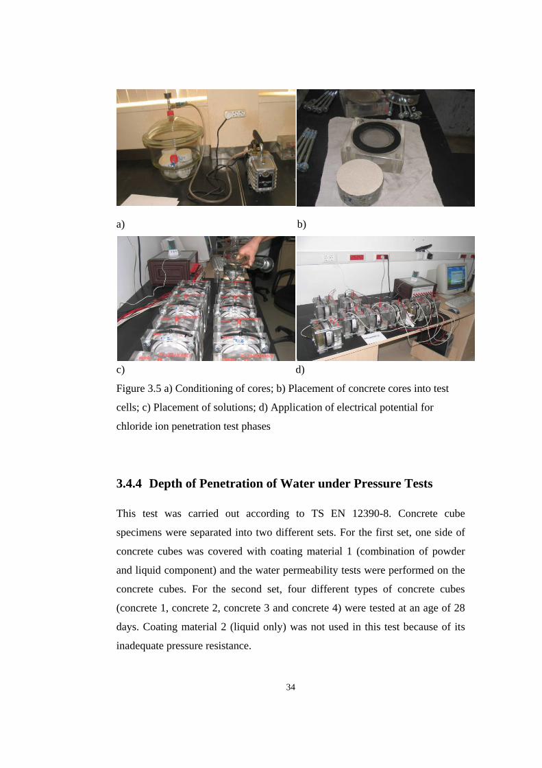
3.4.4 Depth of Penetration of Water under Pressure Tests
This test was carried out according to TS EN 12390-8. Concrete cube
specimens were separated into two different sets. For the first set, one side of
concrete cubes was covered with coating material 1 (combination of powder
and liquid component) and the water permeability tests were performed on the
concrete cubes. For the second set, four different types of concrete cubes
(concrete 1, concrete 2, concrete 3 and concrete 4) were tested at an age of 28
days. Coating material 2 (liquid only) was not used in this test because of its
inadequate pressure resistance.

35
In this test, the depth of penetration of water under pressure into hardened
concrete was determined. Pressurized water was applied to the surface of
hardened concrete and then that specimen was split and depth of penetration of
the waterfront was measured. Cubic concrete specimens with 150x150x150
mm dimensions and older than 28 days were placed into the test apparatus.
Then a water pressure of 500 ± 50 kPa was applied for 72 ± 2 hours. The
specimen was split and the maximum depth of penetration under the test area
was measured. Tap water was used in this test.
a) b)
Figure 3.6 a) Application of water pressure to cube specimens; b) Wetted-front
after water penetration test

36
CHAPTER 4
4 RESULTS AND DISCUSSION
Test results as a whole stated the effects of different coating materials and
different concrete constituents on the permeability properties of the concrete.
4.1 Concrete Compressive Strength Test Results
Table 4.1 and see Figure 4.1 show the compressive strength progress for 28
days, 90 days and 365 days for four different concrete types. Also air contents
and slump values for fresh concrete phase were measured in order to examine
fresh concrete properties and concrete compressive strength relation.
Table 4.1 Concrete compressive strength test results (cube specimens of
150x150x150 mm) and fresh concrete properties
Concrete
Id.
28-day
compressive
strength
value (MPa)
90-day
compressive
strength
value (MPa)
365-day
compressive
strength
value (MPa)
Air
Content
of Fresh
Concrete
(%)
Slump
Value
(cm)
C1 64.2 76.1 86.0 3.6 27.0
C2 38.0 47.4 76.0 7.0 17.0
C3 56.3 56.5 62.0 7.0 18.5
C4 44.4 49.8 52.0 8.0 17.0
REF 34.3 - - 2.0 18.0
37
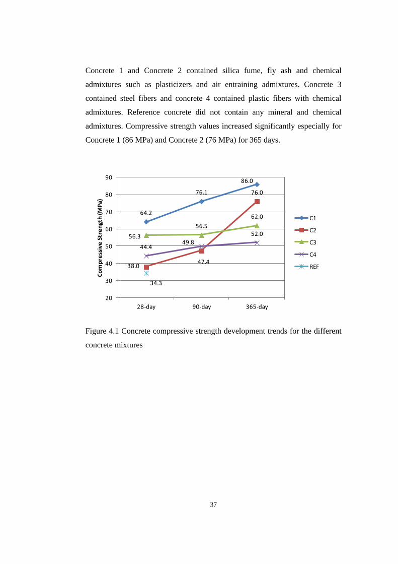
Concrete 1 and Concrete 2 contained silica fume, fly ash and chemical
admixtures such as plasticizers and air entraining admixtures. Concrete 3
contained steel fibers and concrete 4 contained plastic fibers with chemical
admixtures. Reference concrete did not contain any mineral and chemical
admixtures. Compressive strength values increased significantly especially for
Concrete 1 (86 MPa) and Concrete 2 (76 MPa) for 365 days.
Figure 4.1 Concrete compressive strength development trends for the different
concrete mixtures
64.2
76.1
86.0
38.047.4
76.0
56.3
56.5
62.0
44.449.8
52.0
34.3
20
30
40
50
60
70
80
90
28-day 90-day 365-day
Co
mp
ress
ive
Str
en
gth
(MP
a)
C1
C2
C3
C4
REF

38
4.2 Concrete Water Absorption Test Results
Table 4.2 and Figure 4.2 show significant decrease in water absorption rates for
increased concrete constituent properties and concrete specimens coated with
coating materials when compared with the reference specimens.
Table 4.2 Water absorption amounts for different coating materials and
different concrete types
Specimen Id.
Water
Absorption
(%)
Percentage of
Reference
Concrete (%)
First Set of Specimens
Ref. Concrete 2.21 100
Ref.C+M-1 0.27 12
Ref.C+M-2 0.29 13
Second Set of Specimens
Concrete 1 0.34 15
Concrete 2 0.96 43
Concrete 3 0.55 25
Concrete 4 0.79 36
a) b)
Figure 4.2 a) Water absorption amounts for the different mixtures; b) Water
absorption comparisons
2.21
0.27 0.29 0.34
0.96
0.55
0.79
0
0.5
1
1.5
2
2.5
Wa
ter
Ab
sorp
tio
n A
mo
un
ts (
%)
Series1
100
12 13 15
43
25
36
0
20
40
60
80
100
120
% o
f R
ef.
Co
ncr
ete
Series1

39
It was found that both coating materials and concrete 1 showed significant
improvement in resistance to water absorption compared to reference
concretes. Relation between compressive strength and water absorption
amounts is given in Figure 4.3.
Figure 4.3 Relation between compressive strength and water absorption
4.3 Chloride Ion Penetration Test Results
Table 4.3 and Figure 4.4 show significant decrease in chloride ion penetration
values for increased concrete constituent properties including lower w/c ratio,
silica fume, fly ash and coating materials applied concrete specimen when
compared with reference specimen. Evaluation of the results was carried out
according to Table 4.4.
2.21
0.34
0.96
0.55
0.79
y = -1.76ln(x) + 8.13R² = 0.75
0
0.5
1
1.5
2
2.5
0 20 40 60 80 100
Wat
er
abso
rpti
on
(%
)
Compressive Strength (MPa)
Series1
Log. (Series1)

40
Table 4.3 Chloride ion penetration test results for the two coating materials and
different concrete types
Specimen Id.
Measured
Charge
Passed
(Coulombs)
Percentage of
Reference
Concrete (%)
First Set of Specimens
Ref. Concrete 4778 100
Ref.C+M-1 1170 24
Ref.C+M-2 2364 49
Second Set of Specimens
Concrete 1 112 2
Concrete 2 274 6
Concrete 3 3935 82
Concrete 4 2104 44
a) b)
Figure 4.4 a) Results for chloride ion penetration tests for the two coating
materials and different concrete types; b) Comparisons of the results with
reference concrete
4778
1170
2364
112 274
3935
2104
0
1000
2000
3000
4000
5000
6000
Me
asu
red
Ch
arg
e P
ass
ed
(C
ou
lom
bs)
Series1
100
24
49
2 6
82
44
0
20
40
60
80
100
120
% o
f R
ef.
Co
ncr
ete
Series1

41
Table 4.4 Recommendation for assessing chloride ion (ASTM C 1202)
Chloride Ion Penetrability Based On Charge Passed
Charge Passed (Coulombs) Chloride Ion Penetrability
> 4000 High
2000-4000 Moderate
1000-2000 Low
100-1000 Very Low
< 100 Negligible
Chloride ion penetration test results showed that chloride ion penetration
through concrete coated with coating material 1 was low and it was moderate
for concrete coated with coating material 2. For concrete 1 and concrete 2,
chloride ion penetration was almost negligible whereas these amounts for
concrete 3 and concrete 4 were high. This was associated with plastic fibers in
concrete 4 and especially steel fibers for concrete 3. Compressive strength and
chloride ion penetration relation for different concretes is given in Figure 4.5.

42
Figure 4.5 Compressive strength and chloride ion penetration relation
4.4 Depth of Penetration of Water under Pressure Test Results
Table 4.5 and Figure 4.6 show significant decrease in water penetration for
four different concretes and for concrete coated with coating material 1 when
compared with reference specimens.
Table 4.5 Results of depth of water penetration under pressure tests
Specimen Id.
Measured
Penetration
Depth Value
(mm)
Percentage of
Reference
Concrete (%)
First Set of Specimens
Ref. Concrete 59.3 100
Ref.C+M-1 39.2 66
Ref.C+M-2
Second Set of Specimens
Concrete 1 17.5 30
Concrete 2 24.5 41
Concrete 3 22.0 37
Concrete 4 31.5 53
4778
112274
3935
2104
y = -4965ln(x) + 22495R² = 0.72
0
1000
2000
3000
4000
5000
6000
0 20 40 60 80 100
Ch
arge
pas
sed
(C
ou
lom
bs)
Compressive Strength (MPa)
Series1
Log. (Series1)

43
a) b)
Figure 4.6 a) Results for depth of water penetration values under pressure; b)
Comparisons of the results with reference concrete
Results of water penetration under pressure test showed an improvement in
resistance to water penetration with Coating material 2 and other four different
concrete types. Improvement with Coating material 2 was smaller than with the
other four types of concretes. Compressive strength and depth of penetration of
water under pressure relation is given in Figure 4.7.
Figure 4.7 Compressive strength and water penetration depth relation
59.3
39.2
17.5
24.522.0
31.5
0.0
10.0
20.0
30.0
40.0
50.0
60.0
70.0
Me
asu
red
pe
ne
tra
tio
n d
ep
th (
mm
)
Series1
100
66
30
41 37
53
0
20
40
60
80
100
120
% o
f R
ef.
Co
ncr
ete
Series1
59.3
17.5
24.522
31.5
y = -48.47ln(x) + 216.59R² = 0.59
0
10
20
30
40
50
60
70
0 20 40 60 80
Wat
er
pe
ne
trat
ion
de
pth
(mm
)
Compressive Strength (MPa)
Series1
Log. (Series1)

44
4.5 Discussion of Test Results
Compressive strength test results for reference concrete and for the four
different types of concrete showed that, decrease in water-to-cementitious
material ratio and addition of mineral admixtures led to significant increases in
compressive strength. Silica fume and fly ash use in concrete also resulted in
significant compressive strength development over time. A positive correlation
was obtained between concrete compressive strength and concrete
impermeability for four different concrete types. As an exception, Concrete 2
which contained mineral admixtures had lower water penetration depth results
despite having relatively low 28-day compressive strength values for 28 days.
In the literature, it is stated that decrease in water-to-cementitious material ratio
leads to increase in compressive strength. The results were consistent with this
statement. Moreover, for the use of mineral admixtures such as silica fume and
fly ash in concrete, it is stated that they result in a denser microstructure and an
improvement over time in compressive strength values in the case of extending
curing conditions as a result of pozzolanic reactions with calcium hydroxide
(ACI 234R; Song et al., 2011). This is also consistent with the test results
which showed increases in compressive strength values compared to reference
concrete specimens. Also significant improvement in strength was detected for
concrete including silica fume and fly ash over time from 28 days to 90 and
365 days.
Significant decreases in water absorption and chloride ion penetration observed
when coating material 1 was used. For coating material 2, water absorption
decreased significantly but chloride ion penetration decreased moderately.
Water penetration under pressure test results showed moderate decrease for
concrete coated with coating material 1. The results were consistent with the

45
literature review information about coating materials in general (ACI 201.2R-
01; ACI 546.R04; Swamy and Tanikawa, 1993). However the resistance of
coating material 2 to chloride ion penetration was found to be moderate.
Significant improvement in resistance to water absorption, chloride ion
penetration, and water penetration was found for concrete 1. This was
associated with the improvement in impermeability because of decrease in
water/cementitious material ratio and addition of silica fume and fly ash (ACI
234 2R; Erdoğan, 2003; Hover, 2011; Neithalath and Jain, 2010). This
reduction in permeability was thought to result from pore size refinement,
reduction in capillary pores, Ca(OH)2 reduction, extra C-S-H formation, and
cement paste-aggregate interfacial refinement as a result of pozzolanic reaction
between mineral admixtures (silica fume and fly ash) and calcium hydroxide
(Ca(OH)2). For concrete 2, improvement in resistance to water absorption and
resistance to water penetration was lower than for concrete 1. However,
especially improvement in resistance to chloride penetration was higher for
concrete 1 and concrete 2 than resistance of coating materials. For concrete 3
with steel fibers, resistance to chloride ion was very low which can be
associated with the electrical conductivity of steel fibers and water penetration
was moderate. For concrete 4, resistance to water absorption, chloride ion
penetration and water penetration were moderate. These results were associated
with negative effects of fiber during placing and mixing processes during
concrete production. These problems in turn may have led to heterogeneity and
weakening of the concrete microstructure.
Errors in the test results were minimized by increasing the numbers of test
specimens. Moreover, probable damages causing errors in the results were
minimized during the coring process for test specimens and also errors were
minimized because of application of the same testing processes for all types of

46
specimens. Increase in the test time and pressure used in the water penetration
test to provide a better comparison for reference concrete and reference
concrete coated with coating material may result in certain errors for the
comparisons with other four concrete mixtures.
Test results as a whole revealed an improvement in impermeability after
application of the two coating materials on to concrete specimens and
adjustments of the concrete constituents. When test results were analyzed,
improvements due to coating materials applications were associated with the
outer layer resistance to permeation of water and chloride ions. Improvement
due to changes in the constituent of concrete types was associated with
improvement in the microstructure of concrete and improvement in hydration
process which in turn resulted in the improvement in impermeability of
concrete (EM 1110-2-2002; Neville, 2000; Roy, 1986 cited in Arjunan, 2000).
Application of coating materials to the concretes which are not impermeable
was found to be effective of course based on the coating material
characteristics. However, the analyses of concretes having lower water-to-
cementitious material ratio and containing mineral admixtures such as silica
fume and fly ash showed lower permeability values than concretes coated with
coating materials. This result proved that, application of proper coating
material on hardened concretes makes sense only for concretes with high
permeability.

47
CHAPTER 5
5 CONCLUSION AND RECOMMENDATIONS
5.1 Conclusion
This study has been carried out to examine the effects of coating materials and
mixture constituents on the permeability of concrete. Coating material
application on hardened concrete was analyzed for concretes having different
permeability properties. Also, the effect of using mineral admixtures such as
silica fume and fly ash; and effect of water-to-cementitious material ratio;
effect of using steel and plastic fibers on impermeability improvement of
concrete were examined.
The following conclusions were drawn:
Coating material application to hardened concrete significantly
decreased permeability of concrete specimens. Moreover, the properties
of concrete and their constituents were found to be important when
evaluating the effect of the coating materials. Coating materials were
found to be less effective for concretes which were almost
impermeable.
Coating material application to hardened concretes could be considered
as a prevention method for concrete having high permeability.

48
Effectiveness of coating materials was found to vary with their
chemical and physical characteristics.
Water-to-cementitious material ratio, silica fume and fly ash contents of
concrete were found to be the major factors affecting permeability of
the concrete. Concrete permeability had a tendency to decrease when
water to cementitious material ratio decreased and silica fume and fly
ash was used in concrete. This result was associated with reduction in
capillary pores due to low water/cement ratio and pozzolanic reaction
between mineral admixtures and calcium hydroxide. Moreover, the use
of plasticizers was required for low water/cementitious material ratios
to prepare the concrete in order to hold slump values over 15 cm to
make these concretes workable.
Significant improvement was obtained for compressive strength
development for concretes containing silica fume and fly ash over time
from 28 days to 365 day.
Positive correlation was found between concrete compressive strength
and concrete impermeability.
Although water-to-cementitious ratio was decreased in important
amounts, permeability of concrete containing steel fibers did not
decrease in significant amounts. This was considered to be a result of
negative effects of steel fibers in mixing, placing and hydration process
of cementitious material in fresh concrete phase. Especially chloride ion
penetration was high for this concrete which was related to conductivity
of steel fibers.

49
Permeability of concrete containing plastic fibers did not decrease
significantly. This was associated with the problems about plastic fiber
during mixing and placing fresh concrete which in turn resulted in
heterogeneous distribution of fibers in concrete.
5.2 Recommendations
Application of coating materials should be carried out considering
material amounts, application methods, climatic conditions for
application, workmanship, and concrete conditions.
Resistance of coating materials to outside effects, their long-term
sustainability and their adhesion characteristics to concrete surface
should be considered and evaluated in detail.
Admixtures which are used to reduce w/c and to offer higher slump
values should be investigated for their negative impacts on the concrete
and they should be used in reliable amounts and reliable ways.
Different cement types should be used to examine their effects on
concrete permeability.
Impermeability improvement methods should be carried out
considering importance of concrete structures, usage aim of the
structure and practical applicability of the method.

50
REFERENCES
1. ACI 116.R. Cement and Concrete Terminology. Detroit: American
Concrete Institute; 2005.
2. ACI 201.2R. Guide to Durable Concrete. Detroit: American Concrete
Institute; 2001.
3. ACI 232.2R. Use of Fly Ash in Concrete. Detroit: American Concrete
Institute; 2003.
4. ACI 234.R. Guide for the Use of Silica Fume in Concrete. Detroit:
American Concrete Institute; 2006.
5. ACI 318R. Building Code Requirements for Structural Concrete
Commentary, 2005.
6. ACI 546.R. Concrete Repair Guide. Detroit: American Concrete Institute;
2004.
7. Arjunan P., (2000), Ph.D. Thesis, “Detailed Characterization of Current
North American Portland Cements and Clinkers and The Implications For
The Durability of Modern Concrete’’, The Graduate School Intercollege
Graduate Program In Materials, The Pennsylvania State University, U.S.
8. ASTM C 1202-05. Standard Test Method for Electrical Indication of
Concrete’s Ability to Resist Chloride Ion Penetration (2005)
9. Bekaert, 2012. Dramix 80/60 Available at <
http://pdf.directindustry.com/pdf/bekaert/dramix-rc-80-60-bn/5919-
56674.html> (Accessed 5 January 2012)
10. BASF, 2012, Full range water reducer admixture. Available at <
http://www.basf-
admixtures.com/SiteCollectionDocuments/Data%20Sheets/HRWR/PRE-
DAT-0055%20Glenium%203030NS%20062710_WEB.pdf> (Accessed 14
January 2012)

51
11. Canadian Strategic Highway Research, 1995. Concrete Durability
Technical Brief # 5 (online). Available at<
http://www.cshrp.org/products/csbf-e5.pdf> (Accessed 25 November
2011).
12. Coating Material 1. Available at <http://www.basf-
yks.com.tr/TR/urunler/yapi_sistemleri/suyalitim/masterseal_525/Pages/def
ault.aspx> (Accessed 10 January 2012)
13. Coating Material 2. Available at <http://www.basf-
yks.com.tr/TR/urunler/yapi_sistemleri/mimariyuzeykoruyucular/protectosil
_bhn/Pages/default.aspx> (Accessed 10 January 2012)
14. DSĠ (State Hydraulic Works) Technical Research and Quality Control
Department Concrete-Material Laboratory Equipment and Technical
Specifications, 2009. Ankara, Turkey.
15. EM 1110-2-2002, Evaluation and Repair of Concrete Structures Chapter 3:
Causes of Distress and Deterioration of Concrete. US Army Corps of
Engineers.
16. Erdoğan, T.Y., 2003. Concrete. Ankara: METU Press.
17. Forta Ferro, 2012. Macrofiber Concrete Reinforcement Available at <
http://www.forta-ferro.com/products/macrofibers/forta-ferro/> (Accessed
10 January 2012)
18. Hover, K.C., The influence of water on the performance of concrete.
Construction and Building Materials, 25, (2011) 3003–3013.
19. Mehta, P.K., Concrete: structure, properties and materials, Prentice-Hall,
Englewood Cliffs, NJ, 1986, pp 18-36, 111-128, 252.
20. Mindess, S., Young, J.F. and Darwin, D. 2003. Concrete. 2nd
Edition.
Pearson Education, Inc. NJ, USA.
21. Neithalath, N. and Jain, J. 2010. Relating rapid chloride transport
parameters of concretes to microstructural features extracted from electrical
impedance. Cement and Concrete Research, 40 (2010) 1041–1051.
22. Neville, A.M., Properties of Concrete, Harlow, England; New York:
Prentice Hall/Pearson Education, 2000, pp.8, 10, 482-485.

52
23. Özel, N., 2012 BASF Construction Chemicals Region Director. Test
Report for Sugözü Energy Plant Fly Ash, 2009. TÇMB Independent
Quality Control Testing Laboratories. (Personal communication 20 January
2012).
24. Poon, C.S., Kou, S.C. and Lam, L., 2006. Compressive strength, chloride
diffusivity and pore structure of high performance metakaolin and silica
fume concrete. Construction and Building Materials (e-journal) 20 (2006)
858–865. Available through Web of Science Database (Accessed 12 May
2011).
25. Sarıcaoğlu, H. Oyak Ready Mixed Concrete, Ankara. Certificate of
Analysis for Silica, 2001. Finnfjord Smeltevertk A/S, Norway (Personal
communication 25 January 2012).
26. Sika, 2012. Water Reducers Available at <
http://www.tekkonengineering.com.tr/pdf/Sikament-
FFN_EN_01072003.pdf> (Accessed 8 January 2012)
27. Sika, 2012. Air Entraining Admixtures Available at <
http://us01.webdms.sika.com/fileshow.do?documentID=37> (Accessed 14
January 2012)
28. Song H., Pack, S., Nam, S., Jang, J. and Saraswathy, V., 2010. Estimation
of the permeability of silica fume cement concrete Construction and
Building Materials (e-journal) 24 (2010) 315–321. (Accessed 16 June
2011)
29. Strategic Highway Research Program (SHRP), National Research Council.
1993 Mechanical Behavior of High Performance Concrete Volume 2,
Production of High Performance Concrete (online). Washington DC.
Available at < http://onlinepubs.trb.org/onlinepubs/shrp/SHRP-C-362.pdf>
(Accessed 26 November 2011).
30. Swamy, R.N. and Tanikawa, S. An external surface coating to protect
concrete and steel from aggressive environments. Materials and Structures,
26 1993, 465-478.
31. ġahin, T. 2012. Limak Cement ġanlıurfa Quality Control Chief. Analysis
Report for CEM I 42,5 N Portland Cement (Personal communication, 25
January 2012).
32. TS 3624, 1981. Test Method for Determination the Specific Gravity the
Absorbtion Water and The Void Ratio In Hardened Concrete. Turkish
Standard.

53
33. TS EN 12390-3, 2003. Testing hardened concrete - Part 3 : Compressive
strength of test specimens. Turkish Standard
34. TS EN 12504-1, Concrete – Concrete tests in structure – Part 1: Core
specimens, taking cores, testing and determination of compressive strength.
Turkish Standard.
35. TS EN 12390-8, 2002. Testing hardened concrete - Part 8: Depth of
penetration of water under pressure. Turkish Standard.

54
APPENDIX A
A. COMPRESSIVE STRENGTH TEST RESULTS
Table A.1 Concrete compressive strength values
Specimen Id.
Specimen Age
(days)
Compressive Strength
(MPa)
CONCRETE 1
C.1-1 28 64.5
C.1-2 28 63.9
C.1.Average 64.2
C.1-3 90 75.3
C.1-4 90 77.0
C.1.Average 76.1
C.1-5 365 86.0
CONCRETE 2
C.2-1 28 39.0
C.2-2 28 37.1
C.2.Average 38.0
C.2-3 90 48.6
C.2-4 90 46.1
C.2.Average 47.4
C.2-5 365 76.0
CONCRETE 3
C.3-1 28 55.6
C.3-2 28 57.0
C.3.Average 56.3
C.3-3 90 52.0
C.3-4 90 61.0
C.3.Average 56.5
C.3-5 365 62.0
CONCRETE 4
C.4-1 28 44.0
C.4-2 28 44.8
C.4.Average 44.4
C.4-3 90 50.0
C.4-4 90 49.5
C.4.Average 49.8
C.4-5 365 52.0

55
Figure A.1 Concrete compressive strength values for different concrete types
(150x150x150 mm)
64.2
76.1
86.0
38.0
47.4
76.0
56.3 56.562.0
44.449.8 52.0
34.3
0.0
10.0
20.0
30.0
40.0
50.0
60.0
70.0
80.0
90.0
100.0
28 Days 90 Days >365 Days
Co
mp
ressio
n S
tren
gth
(M
Pa)
C.1
C.2
C.3
C.4
Ref . Concrete

56
APPENDIX B
B. WATER ABSORPTION TEST RESULTS
Table B.1 Water absorption test results for reference concrete specimens and
reference concrete specimens coated with two different coating materials
Figure B.1 Water absorption comparisons for reference concretes and reference
concrete specimens coated with two different coating materials applied
Specimen Id.
Initial
Mass of
Specimen
(g)
Mass of Specimen after
24 Hours (g)
Mass of
Specimen
after 48
Hours (g)
Water
Absorption
Amounts
%
REF. CONCRETE
REF.C-1 918.1 936.0 937.6 0.021 2.12
REF.C-2 922.2 941.5 943.4 0.023 2.30
REF.C-3 913.8 932.6 934.1 0.022 2.22
REF.C-Average 2.21
REF.C+ Coating Material 1
REF.C+CM1-1 995.5 997.6 998.0 0.003 0.25
REF.C+CM1-2 992.9 995.1 995.7 0.003 0.28
REF.C+CM1-3 1009.1 1011.1 1011.8 0.003 0.27
REF.C+CM1-Average 0.27
REF+ Coating Material 2
REF.C+CM2-1 909.5 911.2 912.2 0.003 0.30
REF.C+CM2-2 934.5 936.3 937.2 0.003 0.29
REF.C+CM2-3 913.9 915.7 916.5 0.003 0.28
REF.C+CM2-Average 0.29
2.12
2.32.22 2.21
0.25 0.28 0.27 0.270.3 0.29 0.28 0.29
0
0.5
1
1.5
2
2.5
Specimen 1 Specimen 2 Specimen 3 Average
Wate
r A
bso
rpti
on
Am
ou
nt
(% W
eig
ht)
REF.C.
REF.C.+CM1
REF.C.+CM2

57
Table B.2 Water absorption results for 4 different types of concrete specimen
types and coating material 2.
Figure B.2 Water absorption amounts for different concrete types
Specimen Id.
Initial
Mass of
Specimen
(g)
Mass of Specimen after
24 Hours (g)
Mass of
Specimen
after 48
Hours (g)
Water
Absorption
Amounts
%
CONCRETE1
C.1-1 939.9 942.5 943.0 0.003 0.33
C.1-2 933.1 935.9 936.4 0.004 0.35
C.1.Average 0.34
CONCRETE2
C.2-1 848.5 854.8 856.2 0.009 0.91
C.2-2 851.6 858.6 860.2 0.01 1.01
C.2.Average 0.96
CONCRETE3
C.3-1 892.7 896.5 897.2 0.005 0.5
C.3-2 885.2 889.5 890.5 0.006 0.6
C.3.Average 0.55
CONCRETE4
C.4-1 861.6 866.9 868.1 0.008 0.75
C.4-2 861.2 866.9 868.3 0.008 0.82
C.4.AV. 0.79
COATING MATERIAL1
CM.1-1 640.6 644.1 647.3 0.01 1.05
CM.1-2 655.5 658.6 661.1 0.009 0.85
CM.1.Average 0.95
0.33 0.35 0.34
0.91
1.010.96
0.5
0.60.55
0.75
0.820.79
1.05
0.85
0.95
0
0.2
0.4
0.6
0.8
1
1.2
Specimen1 Specimen 2 Average
Wate
r A
bso
rpti
on
Am
ou
nt
(% W
eig
ht)
C.1
C.2
C.3
C.4
C.5

58
APPENDIX C
C. RAPID CHLORIDE ION PENETRATION TEST
RESULTS
Table C.1 Chloride ion penetration test results for reference concretes and
coating materials applied ref. concretes
Specimen Id.Maximum
Temperature ( °C)
Measured Charge
Passed, (Coulombs)
REF. CONCRETE
REF.C-1 - 4215.0
REF.C-2 51 5930.0
REF.C-3 37 3250.0
REF.C-4 47 5263.0
REF.C-5 43 4787.0
REF.C-6 47 5223.0
REF.C-Average 4778.0
REF.C+Coating Material 1
REF.C+CM1-1 30 1231.0
REF.C+CM1-2 22 801.0
REF.C+CM1-3 32 1754.0
REF.C+CM1-4 26 892.0
REF.C+CM1-Average 1169.5
REF.C+Coating Material 2
REF.C+CM2-1 34 2216.0
REF.C+CM2-2 38 2511.0
REF.C+CM2-Average 2363.5

59
Figure C.1 Chloride ion penetration values for Ref.C. and coating materials
Figure C.2 Chloride penetration average values
4215
5930
3250
5263
4787
5223
1231
801
1754
892
22162511
0
1000
2000
3000
4000
5000
6000
7000
Specimen 1 Specimen 2 Specimen 3 Specimen 4 Specimen 5 Specimen 6
Measu
red
Ch
arg
es (
Co
ulo
mb
s)
REF.C
REF. C. + CM1
REF. C. + CM2
4778
1169.5
2363.5
0
1000
2000
3000
4000
5000
6000
Average
Avera
ge C
harg
es (
Co
ulu
mb
s)
REF.C
REF.C+CM1
REF.C+CM2

60
Table C.2 Chloride ion penetration test results for different types of concretes
Figure C.3 Chloride ion penetration values for different concretes
Specimen Id.Maximum
Temperature (C)
Measured Charge
Passed, (Coulombs)
CONCRETE1
C.1-1 23 112
C.1-2 22 112
C.1.Average 112
CONCRETE2
C.2-1 21 271
C.2-2 23 277
C.2.Average 274
CONCRETE3
C.3-1 36 2929
C.3-2 45 4941
C.3.Average 3935
CONCRETE4
C.4-1 34 2210
C.4-2 31 1998
C.4.Average 2104
112 112 112271 277 274
2929
4941
3935
22101998 2104
276
640458
0
1000
2000
3000
4000
5000
6000
Specimen 1 Specimen 2 Average
Measu
red
Ch
arg
es (
Co
ulo
bm
s)
Specimen Numbers
C.1
C.2
C.3
C.4
Material1

61
APPENDIX D
D. DEPTH OF PENETRATION TEST RESULTS
Table D.1 Depth of penetration of water under pressure for ref. concrete
specimen and coating material applied ref. concrete specimen
Figure D.1 Water penetration depth under pressure test results for ref. concrete
and coating material 1 applied ref. concrete
Specimen Id.
Applied
Water
Pressure,
(bar)
Specimen
Age
(days)
Test Period
(days)
Measured
Penetration
Depth
Value,
(mm)
REF. CONCRETE
REF.C-1 7 65 7 60.0
REF.C-2 7 65 7 32.0
REF.C-3 7 64 7 42.0
REF.C-4 6 97 7 77.0
REF.C-5 6 97 7 95.0
REF.C-6 6 96 7 50.0
REF.C-Average 59.3
REF.C+ Coating Material 1
REF.C+CM1-1 7 65 7 44.0
REF.C+CM1-2 7 59 7 27.0
REF.C+CM1-3 7 64 7 47.0
REF.C+CM1-4 6 97 7 17.0
REF.C+CM1-5 6 96 7 32.0
REF.C+CM1-6 6 91 7 32.0
REF.C+CM1-Average 33.2
60
32
42
77
95
50
59.3
44
27
47
17
32 32 33.2
0
10
20
30
40
50
60
70
80
90
100
Wate
r P
en
etr
ati
on
Dep
ths (
mm
)
REF. CONCRETE
REF. CONCRETE+CM1.

62
Table D.2 Depth of penetration under pressure test results for 4 different types
of concrete specimens
Figure D.2 Water penetration depth test results for different concrete types
Specimen Id.
Applied
Water
Pressure,
(bar)
Specimen
Age
(days)
Test Period
(days)
Measured
Penetration
Depth
Value,
(mm)
CONCRETE1
C.1-1 5 31 3 15.0
C.1-2 5 31 3 20.0
C.1.Average 17.5
CONCRETE2
C.2-1 5 32 3 26.0
C.2-2 5 32 3 23.0
C.2.Average 24.5
CONCRETE3
C.3-1 5 32 3 25.0
C.3-2 5 32 3 19.0
C.3.Average 22.0
CONCRETE4
C.4-1 5 31 3 35.0
C.4-2 5 31 3 28.0
C.4.Average 31.5
15
20
17.5
26
2324.525
19
22
35
28
31.5
0
5
10
15
20
25
30
35
40
Specimen 1 Specimen 2 Average
Wate
r P
en
etr
ati
on
Dep
ths (
mm
)
C.1
C.2
C.3
C.4