EFFECT OF AGGRESSIVE ENVIRONMENTS ON … · EFFECT OF AGGRESSIVE ENVIRONMENTS ON MECHANICAL...
37
1 EFFECT OF AGGRESSIVE ENVIRONMENTS ON MECHANICAL PERFORMANCE OF FIBRE CERAMIC COMPOSITES Award No. FA 4869 – 06 -1 -0046 Asian Office of Aerospace Research & Development (AOARD) 7-23-17, Roppongi, Minato-Ku, Tokyo, 160-0032, JAPAN Prof. V. K. SRIVASTAVA Co-ordinator Department of Mechanical Engineering Institute of Technology Banaras Hindu University VARANASI – 221005, INDIA July 2007
Transcript of EFFECT OF AGGRESSIVE ENVIRONMENTS ON … · EFFECT OF AGGRESSIVE ENVIRONMENTS ON MECHANICAL...

1
EFFECT OF AGGRESSIVE ENVIRONMENTS ONMECHANICAL PERFORMANCE OF FIBRE
CERAMIC COMPOSITES
Award No. FA 4869 – 06 -1 -0046Asian Office of Aerospace Research & Development (AOARD)7-23-17, Roppongi, Minato-Ku, Tokyo, 160-0032, JAPAN
Prof. V. K. SRIVASTAVACo-ordinator
Department of Mechanical EngineeringInstitute of Technology
Banaras Hindu UniversityVARANASI – 221005, INDIA
July 2007
Report Documentation Page Form ApprovedOMB No. 0704-0188
Public reporting burden for the collection of information is estimated to average 1 hour per response, including the time for reviewing instructions, searching existing data sources, gathering andmaintaining the data needed, and completing and reviewing the collection of information. Send comments regarding this burden estimate or any other aspect of this collection of information,including suggestions for reducing this burden, to Washington Headquarters Services, Directorate for Information Operations and Reports, 1215 Jefferson Davis Highway, Suite 1204, ArlingtonVA 22202-4302. Respondents should be aware that notwithstanding any other provision of law, no person shall be subject to a penalty for failing to comply with a collection of information if itdoes not display a currently valid OMB control number.
1. REPORT DATE 21 AUG 2007
2. REPORT TYPE FInal
3. DATES COVERED 26-04-2006 to 06-08-2007
4. TITLE AND SUBTITLE Effect of Aggressive Environment on Mechanical Performance of FiberCeramic Composites
5a. CONTRACT NUMBER FA48690610046
5b. GRANT NUMBER
5c. PROGRAM ELEMENT NUMBER
6. AUTHOR(S) Vijay Srivastava
5d. PROJECT NUMBER
5e. TASK NUMBER
5f. WORK UNIT NUMBER
7. PERFORMING ORGANIZATION NAME(S) AND ADDRESS(ES) Banaras Hindu University, Institute of Technology,BHU, Institute ofTechnology,Varanasi.,Varanasi 221005 India,IN,221005
8. PERFORMING ORGANIZATIONREPORT NUMBER N/A
9. SPONSORING/MONITORING AGENCY NAME(S) AND ADDRESS(ES) AOARD, UNIT 45002, APO, AP, 96337-5002
10. SPONSOR/MONITOR’S ACRONYM(S) AOARD
11. SPONSOR/MONITOR’S REPORT NUMBER(S) AOARD-064042
12. DISTRIBUTION/AVAILABILITY STATEMENT Approved for public release; distribution unlimited
13. SUPPLEMENTARY NOTES
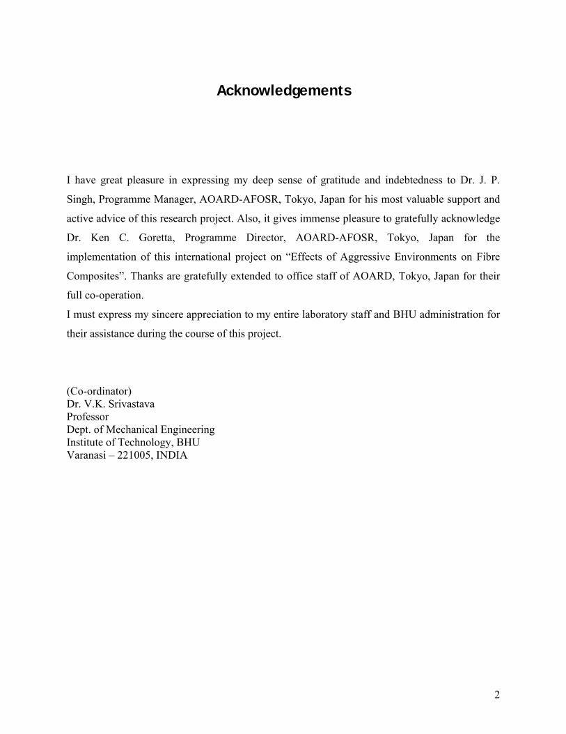
14. ABSTRACT Based on the experimental observation, the results clearly indicate that weight of C/C-SiC composite isdamaged severally at about 2% and 2D C/C composite damaged nearly 12%, when oxidised in openatmosphere by the flame of oxy-acetylene gas. The changes in microhardness, XRD pattern and thermalproperties are appeared because of delamination, debonding, pyrolysis of matrix and formation of CO,CO2 and SiO2. Therefore, maximum tensile and compressive stress of ceramic composites decreased withthe oxidation time in open atmosphere by oxyacetylene gas flame. Also, SiC ceramic coating on 4D carboncomposites resulted that the carbon?carbon composite temperature predicts the oxidation kinetic is severeafter 1273K. This was due to formation of smooth silicon carbide film phases covering the surface of thecomposite. Which is less volatile and showed lower oxygen permeability, and consequently acted as aneffective oxygen diffusion barrier? The whole study show that a combination of both silicon and carbonbased materials system is more useful for elevated oxidation protection of carbon-carbon composites.
15. SUBJECT TERMS Ceramic Matrix Composites, Carbon-Carbon composites, C/C composites, C/C composites,microstructure, properties, joining
16. SECURITY CLASSIFICATION OF: 17. LIMITATION OF ABSTRACT Same as
Report (SAR)
18. NUMBEROF PAGES
36
19a. NAME OFRESPONSIBLE PERSON
a. REPORT unclassified
b. ABSTRACT unclassified
c. THIS PAGE unclassified
2
Acknowledgements
I have great pleasure in expressing my deep sense of gratitude and indebtedness to Dr. J. P.
Singh, Programme Manager, AOARD-AFOSR, Tokyo, Japan for his most valuable support and
active advice of this research project. Also, it gives immense pleasure to gratefully acknowledge
Dr. Ken C. Goretta, Programme Director, AOARD-AFOSR, Tokyo, Japan for the
implementation of this international project on “Effects of Aggressive Environments on Fibre
Composites”. Thanks are gratefully extended to office staff of AOARD, Tokyo, Japan for their
full co-operation.
I must express my sincere appreciation to my entire laboratory staff and BHU administration for
their assistance during the course of this project.
(Co-ordinator)Dr. V.K. SrivastavaProfessorDept. of Mechanical EngineeringInstitute of Technology, BHUVaranasi – 221005, INDIA

3
LIST OF CONTENTS
Acknowledgements i
Details of expenditure ii
1. Introduction 1
1.1. Carbon-carbon composite 1
1.2. Carbon-carbon-silicon-carbide composites 3
1.3. Comparative chart 7
2. Experimental procedure 8
2.1. Materials preparation & tests 8
2.1.1. C/C composites 8
2.1.2. C/C-SiC composites 8
2.2. Effect of oxidations 10
2.2.1. Exposure with gas flame on C/C-SiC composites 10
2.2.1.1 Microharness test 12
2.2.1.2. XRD & thermal analysis 13
2.2.2. Exposure of temperature on C/C composites 15
2.2.2.1. Oxidation performance of SiC coated C/C composite 18
2.2.3. Mechanical performance of composites 20
2.2.3.1. Tensile & compressive tests 20
2.2.3.2. SEM test 25
3. Discussions 26
3.1. Effects of oxidation on composites 26
3.2. Micro-performance of composites 28
4. Conclusions 29
5. References 30
6. Publications 32
7. Work schedule for 2nd year 32
8. Grant required for 2nd year 32

4
Details of Expenditure:
i. Sanctioned Amount: $ 23160.0 (Rs. 10.82 Lakh)
ii. Expenditure:
S. No. Items Price, Rs.
1. Automated Universal Testing Machine, 2,68,275.0
2. Pentium x 4 Computer with Laser Printer 44690.0
3. Electronic Balance 4500.0
4. Soldering kits 6525.0
5. Advertisement 1,15,245.0
6. Salary and travel 2,85,000.0
7. Contingency, materials and stationary, postageetc.
3,58,000.0
Total 10,82,235.00
5
1. INTRODUCTION:
1.1. Carbon-Carbon Composites
Carbon–carbon (C/C) composite materials have been developed in the 1960s to satisfy the needs
of high temperature applications in different high-tech industries, especially in aerospace and
aeronautics such as the combustion chamber of ballistic missiles, re-entry vehicles, aircraft,
brake discs, etc. C/C composites have many of the desirable high-temperature properties of
conventional carbons, including excellent mechanical properties. In addition, low density, very
low coefficient of expansion, excellent thermal conductivity, high heat absorption capacity, and
stable coefficient of dynamic friction and, finally, a reasonable wear rate produce an
unprecedented material for brake applications. In many of these applications the load is applied
dynamically, resulting in the development of high rates of strain and stress. The ability to predict
failure of these structures under dynamic loading is becoming increasingly important. In
dynamic conditions, disturbances in the form of stress waves emanate from the point of impact
and propagate through the structure. Propagation of these waves through C/C composites will be
significantly different from what is usually found with homogeneous materials. Because of the
complexity introduced by the inertia forces, such as variation in the properties with the rate of
loading, damage initiation and growth during the loading process, the principles of dynamic
elasticity have not been well understood. To study the complex phenomena associated with the
stress waves, a clear distinction must be made between the material response and the structural
response. On this latter point it is noted that the response of a structure depends on its geometry,
the point of application of the load, and the way in which the material comprising the structure
responds.
Carbon is often used as a construction material for high temperature, non-oxidizing systems.
Modern carbon materials such as continuous fiber reinforced carbon composites (CFRCC) are
being developed for commercial as well as aerospace applications [1]. This include heat shields,
aircraft as well as other brake systems, vacuum furnace parts, heat exchangers, lining for
chemical reactors and a host of other industrial applications [2].The performance of these
thermo-structural composites is drastically reduced due to rapid oxidation of carbon at elevated
temperature. The uncoated CFRCC looses its weight and shape with increase in exposed high

6
temperature environment. Gasification of carbon typically begins at 623K with following gas-
solid reactions.
C(s)+½ O2(g) = CO(g) ; at low oxygen potential (1)
C(s)+O2(g) = CO2(g) ; at high oxygen potential (2)
Thermodynamically, unless the oxygen pressure is extremely low (i.e., < ~10–10 atm), some
carbon will always be lost via these reactions. For long term application at such conditions it is
essential that these composites should be protected against oxidation. For this purpose, SiC
ceramics are primarily preferred as the coating material. This is due to their good compatibility
with C/C composites, having reasonable strength, high thermal conductivity, excellent corrosion
and oxidation resistance [3]. However the expected life of SiC coating is limited by its oxidation
properties. At temperatures above 973K in air, Si-C reacts with air to form CO and a silica-rich
surface layer. With change in operating condition, the most obvious chemical issues are
generation of silicon sub oxides and simple vaporization of the oxides at high temperatures. The
vapour species above SiO2(s) consist of a mixture of SiO(g), SiO2(g), and other species
depending on conditions. At low pressure oxygen environment, SiO2 decomposes to an oxygen
product such as:
SiO2 (s) = SiO(g)+ ½ O2(g) (3)
Vaporization leads to material loss, possible roughening of the surface, and deposition of the
crystal composition on colder parts of the system. Often at ‘carbon and SiC’ interface SiO2 is
also formed. C/SiO2 solid phases are not compatible and generate some small amounts of volatile
species within 1000-2000K. Since highly viscous SiO2 is not able to bridge the ‘crazing and
debonding’ of SiC coating, it induces the degradation of SiC coating. For having active crack
bridging therefore, other oxides are necessary.
Thus to have a satisfactory performance of carbon- carbon composites, development of a suitable
functionally gradient anti-oxidation coating is the logical choice [4]. Among all carbon
composites, four directional reinforced composite represents a less studied C/C material system.
Selective materials such as MoSi2 and B4C have promising oxidation resistance at high
temperatures.MoSi2 has a high melting point with excellent high-temperature characteristics and
high resistance against oxidation. There is a good thermodynamic compatibility between SiC and
MoSi2 [5]. MoSi2 exhibits a brittle-to-ductile transition in the vicinity of 1173K–1273K and
7
above this temperature shows significant metal-like ductility [6-7]. Therefore it is expected that
MoSi2 can improve the high temperature functional properties of SiC material and thus has a
Fan and Song et al. have studied fine-grained SiC- B4C doped graphite prepared by the ball
milling dispersion method [8]. It possesses excellent self-healing properties and oxidation
resistance at 1673K. Kobayashi and Miyazaki et al. found that mixing some kinds of ceramic
powders (B4 C–SiC) into the carbon substrates could produce carbon–ceramic composites with
high oxidation resistance and self-healing properties capable of resisting oxidation at high
temperatures [9].
1.2. Carbon-Carbon-Silicon Carbide Composites
To make full use of carbon–carbon composites in high-temperature applications and also in
oxidising atmospheres, additional oxidation protection is required. Oxidation behaviour of
carbon and of carbon–carbon composites have been studied over the past two decades [10-14]
with a view on practical applications of these materials at varying temperatures under different
environmental conditions. This area is still in focus from the point of view of basic scientific
interest, especially when new methods of carbon matrix modification, processing and oxidation
protection for carbon–carbon composites are being explored. Carbon matrix obtained from
different precursors possesses different types of texture and microstructure on which the
oxidation rate largely depends. Silicon based oxidation inhibitors are most popular for oxidation
protection of carbon–carbon composites. They are often added to the matrix either as carbides or
as oxides which then are converted into carbides. An important siliconising process for carbon–
carbon composites is the liquid silicon infiltration (LSI) method to form carbon–carbon silicon
carbide composites (C/C–SiC). This process consists of three major steps. First, a carbon fibre
reinforced plastic is produced. Second, the green composite is pyrolysed and the shrinkage of the
polymeric matrix is hindered by the fibres which lead to the development of a regular crack
pattern. In the last step, the carbon–carbon preform is infiltrated with liquid silicon that reacts to
SiC, yielding a dense material with carbon-carbon segments separated from each other by SiC.
The LSI method leads to a damage tolerant ceramic material that has a significantly lower
component fabrication time and therefore reduced component costs compared with other ceramic
8
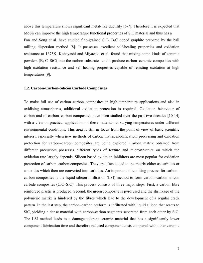
matrix composite (CMC) manufacturing processes [15]. Carbon fibres are the back bone of C/C
and C/C–SiC composites.
Fig. 1. 3D of C/C-SiC Composites
The latest advancement in C/C composites is largely attributed to the improvement in carbon
fibre properties such as stiffness, modulus of elasticity, fatigue strength, and lower thermal
expansion coefficient. High strength and high modulus carbon fibres are about 7–8 µm in
diameter and consist of small crystallites of graphite. In graphite single crystal carbon atoms are
arranged in hexagonal arrays. Very strong covalent bonds are effective in the layer planes while
weak van der Waals forces exist between the layers. High modulus and high strength fibres are
achieved when these layer planes are aligned parallel to the fibre axis. The arrangement of the
layer planes in the direction perpendicular to the axis of fibres influences their transverse and
shear properties [16-17].
However, even after significant progress in the development of C/C composites for aerospace
structures, they still have a severe drawback with respect to their poor response to impact
loading. The impact induced by rigid masses on composite plates is generally slow, since the
time during which the impactor and the plate remain in contact is very long compared with the
lowest period of free vibrations of the bodies. Therefore, impact can be treated as a quasi-static
9
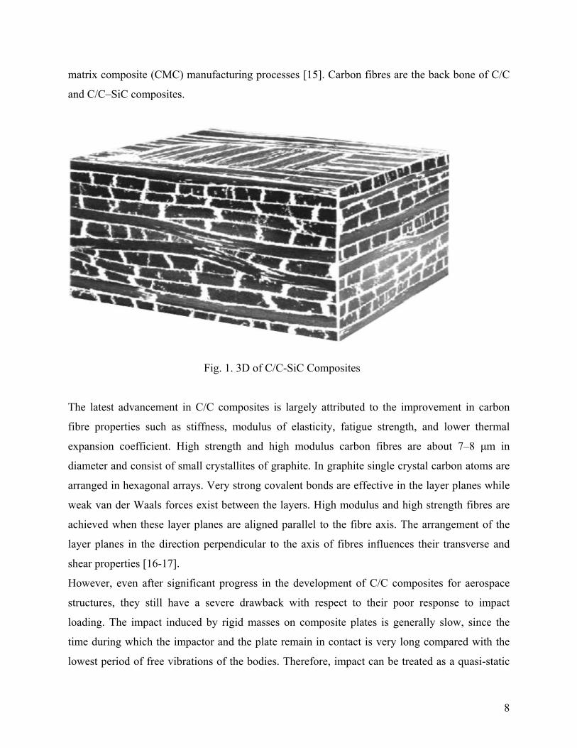
contact because it does not take into account the influence of elastic waves in the interior of the
composite plate. Due to localized impact-induced damage, the structural integrity of composite
reduces significantly with the creation of matrix cracking, delamination and fibre breakage.
Fig. 2. Left handside micrograph of after pyrolysis at 900OC and right handside after
silconinsing process.
These cracks grow into the interlaminar region between crossed plies, and they can be redirected
into the interply as delaminations, if the impact energy is high enough. The delamination caused
during the fracture event severely reduces the residual compressive strength of most laminated
composites [18]. The presence of delamination may degrade severely the stiffness and strength
of composites and in some cases lead to catastrophic failure. Thus, if composite materials are to
play a more important role in industry, then a reliable integrity assessment system has to be
developed. The principle behind damage detection methods based on model analysis is that
damage reduces the dynamic stiffness (EI) of a structure, which results in reduction of the
resonant frequencies [19]. The modulus of elasticity (E), velocity of sound (Cs) and density of
material (ρ) are correlated [20]:
Cs=(E/ρ)1/2 (4)
Where, sound velocity (Cs) is related to the frequency (f) and wave length (λ) by
Cs=fλ. (5)
Combining equation (4) and (5)
f=1/λ(E/ρ)1/2 (6)

10
The above equation shows that the resonant frequency is related to the elastic modulus of the
material. From the rule of mixture, it is also clear that the elastic modulus of the composite (E) is
dependent upon the elastic modulus of fibre (Ef)/matrix (Em) and the volume fractions of fibre
(Vf) and matrix (Vm). This can be written as [17]:
E=EfVf+EmVm, or≈EfVf (since, Ef>Em) (7)
Therefore, E Vf. (8)
Equation (7) and (8) can be used to explain the influence of the damage on resonant frequency.
Thus, the measurement of resonant frequencies of a structure at any stage of its life offers the
possibility of detecting the presence of damage. Monitoring the changes in modal frequencies
can help assess the structural damage, where the frequencies can be measured accurately as in
quality control during manufacture.
The effect of impact damage on the flexural resonant frequency and flexural modulus of C/C–
SiC composites is studied in the present investigations. The damage was introduced by the
impact caused by dropping a weight from different heights on the specimen. The elastic modulus
of the material was determined by grindosonic method, and the crack pattern was monitored by
laser confocal scanning microscopy.

11
1.3. Comparative chart of C/C and C/C-SiC composites [20]
C/C C/C-SiC Materials
Schunk, FRG DLR, FRG Producer
Polymer Pyrolysis LSI Process
1.55-1.65 1.8-1.95 Density, g/cm3
5-8 2-5 Open Porosity, %
150-200 120-190 Tensile Strength, MPa
70-90 50-70 Young’s Modulus, GPa
200-240 200-290 Flexural Strength, MPa
- 210-320 Compressive Strength, MPa
- 55-60 Shear Strength, MPa
8-12 25-30 Interlaminar Shhear Strength, MPa
(RT-1000OC)
0.8
6.9
(RT-1500OC)
1-2
4-6
Coefficient of Thermal Expansion, 10-6 1/K
11 to the fabrics = to the fabrics
60-8
15-25
8-29
6-22
Thermal Conductivity, W/mK
11 to the fabrics = to the fabrics
12
2. EXERIMENTAL PROCEDURE:
2.1. Materials Preparation and tests
2.1.1. C/C composites
The material used in this programme was supplied by NFTDC, Hyderabad, India. Small
substrates of size 12.5 mm x 12mm x 18mm were cut from laboratory prepared 4D carbon–
carbon composite panel having coal tar pitch as matrix precursor with high and uniform fiber
content. The average density of the composite was 1.987 g/cm3 with local hardness varying from
542Hv1 (20 seconds) as minimum to 787 Hv1 (20 seconds) as maximum. The frequent hardness
values were varying between 728 to 787 Hv1. After being hand-polished using 80 grit SiC paper,
these specimens were cleaned ultrasonically with acetone and dried at 373 K for 2 h. The silicon
carbide conversion coating was performed at 1873K for 2 hours. It was followed by development
of MoSi2-Al2O3 and B4C coating on these SiC coated C/C substrate through insitu reaction
sintering.
The dynamic and isothermal oxidation testing were carried out up to 1473K in thermal analysis
system capable of measuring the remained mass in the desired time interval. The system is
having an open air circulated furnace of size 120 mm diameters and 200 mm length. The low
magnification microstructure of the as prepared C/C composite, coated composite before and
after oxidation test were observed using a stereo microscope. The phase contents of samples
including tested one were determined using the Philips Xpert pro diffractometer having
accelerator detector at 40Kv-30amps power. The thickness of the coating were determined
through an optical microscope BX60M of Olympus using ‘image-Pro plus v5.0’ software.
Archimedes principle was used to find the density of the samples.
2.1.2. C/C–SiC composite
The investigations refer to cross-woven C/C–SiC composites with HTA carbon fibre (φ=7 µm)
as reinforcement, and the matrix was silicon carbide. The material parameters are shown in
Table-1.

13
Table 1. Material parameters
Parameter Value
Oreintation
Volume fraction, %
Carbon
Silicon Carbide
Silicon
Density, g/cm3
Elastic Modulus, GPa
Poisson’s Ratio
0/90o
60
38
2
1.85
65
0.182
The material used was manufactured and supplied by DLR (German Aerospace Centre),
Stuttgart. First, carbon fibre reinforced plastic (CFRP) composite is prepared using standard
industrial process of resin transfer moulding (RTM). The CFRP is then pyrolysed at 900°C in
nitrogen atmosphere for the conversion of the resin matrix into carbon. The carbon yield of the
precursor is about 60% by weight, which is accompanied by high shrinkage of the resin up to
about 20% in length. This results in a high amount of matrix cracking which can be distinguished
in irregularly spaced segmentation cracks, micro-delaminations and fibre-matrix debondings
within the segments. In the last stage, carbon–carbon is infiltrated with the molten silicon at
1650 °C in vacuum. Silicon infiltrates the C/C preform rapidly and reacts with both fibre and
matrix to form silicon carbide. Silicon can enter the material only through segmentation cracks
and micro-delaminations during the infiltration process. However, silicon can only infiltrate
them partly because some of the cracks are isolated, and at others the crack opening is so small
that it is closed by the SiC, in which unreacted silicon (2%) can be found. The excess formation
reaction rate of SiC is controlled by the diffusion of silicon atoms through the SiC layer into the
carbon fibres [5].

14
2.2. Effect of Oxidation
2.2.1. Exposure with gas flame on C/C-SiC composites
The 2D C/C-SiC composite plates were cut from the bulk with dimension (1cm x 1cm). The
specimens were cleaned ultrasonically to remove any incompact particle and dried. The samples
were weighted by electronic balance without any exposure and the surface of C/C-SiC composite
was oxidized at temperature about 7000C with the gas flame of Oxy-Acetelyne torch, which is
shown in Fig. (3). The distance was tried to maintain 10mm in between the nozzle of gas and
surface (Fig. 4). C/C-SiC composite plates were oxidized with the variation of the time such as 5
min 10 min, 15 min and 20 minutes and they were weighted again. The cumulative weight
change of samples was reported as a function of oxidation time, as shown in Fig. 5 and skelton of
fibres are visualized from Fig. 6. Percentage of weight loss (∆W) of the samples were calculated
by the following equation
∆W = [Mo– M1 ] / Mo (9)
Fig. 3. Profile of oxy-acetylene torch.

15
Fig. 4. Flame compressed with surface of C/C-SiC composites.
Fig. 5. Variation of weight loss with the variation of time.
Fig. 6. Skelton of fibres after the exposure of gas flame.
0
0.05
0.1
0.15
0.2
0.25
Wt.
loss
(gm
s)
300 600 900 1200
Time (Sec)

16
2.2.1.1. Microhardness tests
Microhardness test is conducted on Shimadzu microhardness tester (HMV-2T). Indenter is made
of diamond in the form of a square based pyramid with an included angle of 136° between
opposite faces. The hardness tester is semi-automatic in which the specimen surface is brought
close to indenter, the preset load is applied for some definite time and load is removed
automatically. The loads are slowly applied to avoid error due to inertia effects. The time of load
application and load duration can be controlled. In the present study, the load ranging from 10 to
100 g is applied for the duration of 5 s and Vickers hardness number is calculated using the
following equation
(10)
(11)
where P is the applied load (N), d is the diagonal of square impression (mm), H is the horizontal
length (mm) and V is the vertical length (mm). Variation of microhardness in various samples
before and after oxidations is plotted in Figs. 7 & 8.
0
200
400
600
800
1000
1200
1400
1600
1800
Mic
roha
rdne
ss, H
v
1 2
Number of samples
Fig. 7 . Variation in microhardness with load of unexposed C/C-SiC composites
Microhardness, HvLoad, Grams

17
2.2.1.2. XRD and Thermal analysis
The oxidized and unoxidized samples were passed through the XRD analysis to find out the
change in mechanical behavior of oxidized and unoxidized samples are mentioned in Fig. 9 &
10. The morphology of each specimen was quite different on microscopic scale due to
conditioning of specimen and loads.
Fig. 9. XRD patterns of unexposed C/C-SiC composites
0
2 0 0
4 0 0
6 0 0
8 0 0
1 0 0 0
1 2 0 0
1 4 0 0
Mic
roha
rdne
ss, H
v
1 2 3
N u m b e r o f s a m p le s
F ig . 6 . V a r ia t io n in m ic ro h a rd n e s s w ith lo a d o f e x p o s e d C -C /S ic c o m p o s ite
M ic ro h a rd n e s s , H v
L o a d , G ra m s

18
Also, unoxidized and oxidized samples were treated with Perkin-Elmer thermal analysis to study
the behavior of samples toward the temperature are illustrated in Figs. 11 & 12..
Finally, scanning electron microscope test was used to evaluate the morphology of fractured
samples.
Fig. 10. XRD pattern of exposed C/C-SiC composites.
Fig. 11. Variation of microvolt with temperature ofunexposed C/C-SiC composite
8.8
8.9
9
9.1
9.2
9.3
9.4
9.5
9.6
9.7
0 200 400 600 800 1000 1200 1400 Tem perature, ( OC )
Mic
rovo
lt, (
V)
19
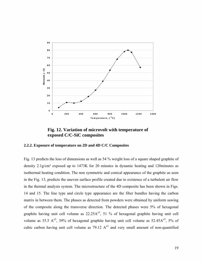
Fig. 12. Variation of microvolt with temperature ofexposed C/C-SiC composites
2.2.2. Exposure of temperature on 2D and 4D C/C Composites
Fig. 13 predicts the loss of dimensions as well as 54 % weight loss of a square shaped graphite of
density 2.1g/cm³ exposed up to 1473K for 20 minutes in dynamic heating and 120minutes as
isothermal heating condition. The non symmetric and conical appearance of the graphite as seen
in the Fig. 13, predicts the uneven surface profile created due to existence of a turbulent air flow
in the thermal analysis system. The microstructure of the 4D composite has been shown in Figs.
14 and 15. The line type and circle type appearance are the fiber bundles having the carbon
matrix in between them. The phases as detected from powders were obtained by uniform sawing
of the composite along the transverse direction. The detected phases were 5% of hexagonal
graphite having unit cell volume as 22.25Ao3, 51 % of hexagonal graphite having unit cell
volume as 35.5 Ao3, 39% of hexagonal graphite having unit cell volume as 52.45Ao3, 5% of
cubic carbon having unit cell volume as 79.12 Ao3 and very small amount of non-quantified
0
1 0
2 0
3 0
4 0
5 0
6 0
7 0
8 0
9 0
0 2 0 0 4 0 0 6 0 0 8 0 0 1 0 0 0 1 2 0 0 1 4 0 0
T e m p e ra tu re , ( O C )
Mic
rovo
lt, (-
V)

20
rhombohedral C70 with 2251.86 Ao3. The finely distributed ‘crater appearance’ as observed in
the figures are the pores developed during the fabrication of the composite.
Fig. 13. Loss of shape and weight (54 w%) of a square shaped dense
expose up to 1473K for 140 minutes.
Fig. 14. Longitudinal views of microstructure of 4D bare carbon composite at 8x
Fig. 15 . Transverse views of microstructure of 4D bare carbon composite at 8x
21
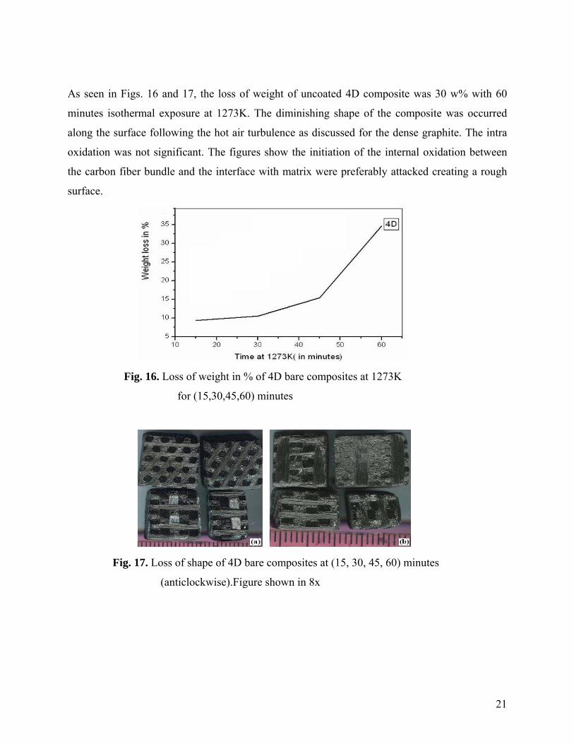
As seen in Figs. 16 and 17, the loss of weight of uncoated 4D composite was 30 w% with 60
minutes isothermal exposure at 1273K. The diminishing shape of the composite was occurred
along the surface following the hot air turbulence as discussed for the dense graphite. The intra
oxidation was not significant. The figures show the initiation of the internal oxidation between
the carbon fiber bundle and the interface with matrix were preferably attacked creating a rough
surface.
Fig. 16. Loss of weight in % of 4D bare composites at 1273K
for (15,30,45,60) minutes
Fig. 17. Loss of shape of 4D bare composites at (15, 30, 45, 60) minutes
(anticlockwise).Figure shown in 8x

22
Fig. 18. Weight of 4D bare as retained in dynamic and isothermal heating condition.
The 4D composite in as-fabricated condition exhibited four type of oxidation regime as in Fig.
18 (a and b). The initial linearity up to 948K indicated the slow surface reaction between the
carbon and oxygen molecules. The change in linearity in-between 948K-1100K shows the
intermediate region where oxidation increased by gaseous diffusion. There was a sharp increase
in surface reaction at crater type defect sites and gaseous diffusion in-between 1100K and
1373K.After 1373K the inward diffusion of oxygen slowed down due to incoming CO and CO2
gases. However the built up pressure inside the composite started cracking it and thus with
isothermal hold at 1473K, the fall in weight of the composite was comparatively faster. After a
total of 100 minutes dynamic as well as isothermal heating, the whole block of the composite
kept for testing collapsed. In all cases it was observed that matrix carbon started oxidizing faster
compared to fiber carbon.
2.2.2.1. Oxidation performance of SiC coatings on C/C composites:
The density and thickness of coatings as determined for coated samples have been presented in
Table 2.
Coating type on C/C Thickness (in micron) Density (g/c3)
SiC 460 2.06
Table 2. Density and thickness of coatings SiC on C/C

23
Fig. 19. (a) A 20µ x 250µ sized cracked as seen in one portion of the SiC coated
on C/C and (b) Macrostructure of the SiC coating on C/C at x 8.
As observed in Fig. 19, rough grayish green region were the matrix region having a crack (Fig
19-a). Rough dark grey region were the matrix region with white spotted alumina regions.
However matrix region although got coated still was rough. Two type of hexagonal SiC (49w %)
and three type of SiO2 (tetragonal: hexagonal: orthorhombic with w% as 5:14:32) were detected
in the oxidized product. Nearly 41w% of SiC has been oxidized to SiO2. However matrix region
although got coated still was rough. cubic (17w %) and hexagonal (66w %) SiC, cubic (7w %)
Si5C3 and 10w% graphite were detected in the as coated SiC – C/C composite (Fig. 20). It
showed cubic SiC is relatively less stable compared to hexagonal SiC. The oxidation weight loss
was 34.7%.
Fig. 20. X-ray diffraction of SiC coating on 4D C/C (a) before oxidation
(portion1), (b) before oxidation (portion 2) and (c) after oxidation

24
2.2.3. Mechanical performance
2.2.3.1. Tensile and compressive tests
The tension and compression tests were generally performed on flat specimens. The most
commonly used specimen geometries are the dog-bone specimen and straight-sided specimen
with end tabs. A uniaxial load is applied through the ends. The ASTM standard test method for
tensile properties of fibre–resin composites has the designation D3039-76. It recommends that
the specimens with fibres parallel to the loading direction should be 12.7 mm wide and mode
with 6–8 plies. Length of the test section should be 153 mm. The test-piece used here is of dog-
bone type and having dimensions according to the standards. The tensile and compressive tests
were performed on the universal testing machine (Fig. 21) and results were analyzed to calculate
the tensile strength of composite samples.
Fig. 21. Experimental set-up of mechanical test.
Compression test:
First of all, compression test was performed on the exposed and unexposed samples of C/C-SiC
and C/C composites. The rectangular sample was fixed in the UTS machine and compressive
load was increased. The sample was crushed out from the lower edge, as shown in Fig. 22 & 23.

25
C/C-SiC composite was fractured abruptly with the combined effects of fibre bending, matrix
cracking, debonding and delamination.
Fig. 22. Fracture deformation of C/C-SiC under compression
Fig. 23. Damage sample of oxidized C/C-SiC under cpmression
Maximum stress was recorded for each sample and results were plotted against the exposure time
to see the loss of strength as can be illustrated in Fig. 24 & 25.

26
130
135
140
145
150
0 5 10 15 20 25
Exposure Time, min
Max
imum
Com
pres
sive
Str
ess,
MPa
Fig. 24. Degradation of maximum compressive stress with increaseof exposure time of gas flame on C/C-SiC
15
17
19
21
23
25
27
29
31
0 5 10 15 20 25
Exposure Time, min
Max
imum
Com
pres
sive
Str
ess,
MPa
Fig. 25. Degradation of compressive stress with increase ofexposure time of gas flame on C/C

27
Tensile test:
All composites sample were exposed with the flame of oxyacetylene gas flame in open
atmosphere with the variation of time from 5 min to 20 min. Exposed samples were presented in
Fig. 26. Each sample was fixed in UTS machine to find out the maximum tensile stress. The load
versus displacement curve was plotted of C/C-SiC and C/C composites, as shown in Fig. 27.
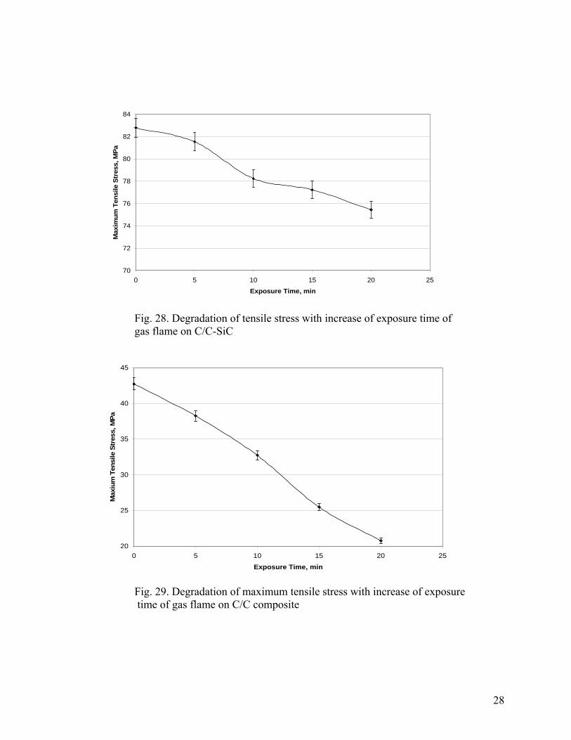
Maximum stress of each sample was also recorded to see the variation in strength with the
increase of exposure time, which is illustrated in Fig. 28 and 29.
Fig. 26. Exposed C/C-SiC samples with oxyacetylene gas flame
0
0.5
1
1.5
2
2.5
3
3.5
0 0.2 0.4 0.6 0.8 1 1.2 1.4 1.6 1.8 2
Displacement, mm
Load
, KN
Fig. 27. Variation of load with displacement of oxidized compositesunder tension.
C/C-SiC
C/C
Breaking point
28
70
72
74
76
78
80
82
84
0 5 10 15 20 25
Exposure Time, min
Max
imum
Ten
sile
Str
ess,
MPa
Fig. 28. Degradation of tensile stress with increase of exposure time ofgas flame on C/C-SiC
20
25
30
35
40
45
0 5 10 15 20 25
Exposure Time, min
Max
ium
Ten
sile
Str
ess,
MPa
Fig. 29. Degradation of maximum tensile stress with increase of exposure time of gas flame on C/C composite

29
2.2.3.2. Scanning electron microscopy test:
The fractured surface of oxidized and unoxidised C/C/SiC and C/C composite specimens was
observed by scanning electron microscope (SEM) method. The deformation of fibres, matrix and
distribution of Si, SiC were quite different on microscopic scale due to conditioning of specimen
and load, which images are shown in Figs. 30-33.
Fig. 30. SEM of C/C/SiC composites without fracture
Fig. 31. SEM of fractured sample of C/C-SiC composites.

30
Fig. 32. C/C Composites without fracture.
Fig. 33. Fractured sample of C/C composites.
3. DISCUSSIONS:
3.1. Effect of oxidation on composites
Due to oxidation of carbon in open atmosphere, C/C-SiC and C/C composites properties was
decreased with increase of exposure time. In the process of oxidation, the matrix undergoes
pyrolysis reaction within short period of time. This generates volatiles and leaves behind a

31
porous skelton of carbon fibres on outer layers and reduces weight of virgin C/C-SiC (2%) and
C/C (>12%) composites. The overall effects on tensile and compressive stress of the composites
can be clearly visualized from the Figs. 24, 25, 28 & 29. The degradation in maximum tensile
stress and compressive stress of C/C-SiC was obtained 8.82% during oxidation process, whereas,
maximum tensile stress and compressive stress of C/C composite was reduced more than
29.32%. This shows that the C/C composite was easily oxidized in open atmosphere. It’s clearly
indicated that the composite surface texture is fully oxidized with the oxidation effect, which
creates more microcracks due to degradation carbon and matrix / fibre interface, as can be seen
from Fig. 32 & 33. However, thermal expansion coefficient of SiC ceramic is largely higher
than that of C/C composite, which induced the formation of cracks. The cracking is caused by
stress development due to the coefficient of expansion mismatch between the carbon fibres and
the SiC matrix. Which also results in through the wall porosity in the composite?
In unexposed sample the average microhadrness is 1740.33 Hv under the 50 gm and with 100
gm it was 1415 Hv (Fig.7), whereas in exposed sample it becomes reduced. The value of
microhardness is decreased from 1740.33 Hv to 1379.33 Hv under the load of 50 gm, 1067 Hv
with 100 gm and 430 Hv with 200 gm (Fig. 8).
This information indicates that the fracture surface of oxidized specimens is different than the
unoxidized C/C-SiC composites.
XRD is used for the phase analysis. In the microstructure of C/C-SiC composite, XRD confirms
the formation of SiC phase, which are made out of Si vapour exposed with carbon fibres. The
microstructure indicates severe reaction between carbon fibre and molten silicon. In the present
study, the XRD pattern used for both type of samples oxidized as well as unoxidized (Fig. 9)
shows the microstructure of unexposed C/C-SiC composite and in Fig. 10, which tells about
exposed C/C-SiC the number and height of peaks become reduced.
This reduction in number and height of peaks is due to the morphological change in the sample.
After oxidation carbon degraded in the form of carbon-di-oxide and carbon-mono-oxide (C+O2
→CO2↑, 2C+O2 →2CO↑) and Si reduce in the form of silicon oxide (Si+O2→ SiO2).
Due to the loss of carbon and silicon particle from the sample, the morphological characters were
changed and hence the reduction in number and height of peak obtained.
Thermal conductivity is a key property in many applications of C/C-SiC composites. Generally
these are relatively good conductors of heat but their conductivity depends upon the crystallinity

32
of their constituents. And due to change in the proportion of oxygen, carbon and silicon, the
conductivity becomes also changed. Figs. 11 and 12 shows the thermal behavior of unoxidized
and oxidised C/C-SiC composites, which clearly indicates that the microvolt increases with
increased of temperature. Whereas the value of microvolt unoxidized is reduced 2% from
oxidized samples. However the value of microvolt increases with increase of temperature upto
1000OC and then reduced abruptly with increase of temperature. The change in texture of
oxidised composite shows different behavior from uinoxidized sample as can be identified from
Fig. 13.
Micro cracking of the matrix increased in weight loss. The cracking was due to the residual
stress field formation resulting from the thermal expansion anisotropy developed because of
presence of Si and Si-C phases. However the coating was too hard before and even after
oxidation. On a gentle loading a portion of coating was removed showing the enhanced
brittleness of the coating after exposed to high temperature.
The surfaces of the oxidation tested samples were identical to the surface before testing. The
most remarkable point was that the matrix was fully protected from oxidation while localized
oxygen attack was observed on the fiber bundles (Fig. 17). Almost all sets of fiber bundle have
been oxidized. This could be the wettability difference between the graphitized carbon fiber and
the generated phase such as SiO2. The formation of each phase can be identified from XRD
patterns as shown in Fig. 20. Another possibility is of consumption of oxidation protection at
these points.
3.2. Micro performance of composites
The micro observation of oxydised and unoxidised fracture sample of composites were
illustrated that the virgin composites severally affected by the oxidation in open atmosphere. The
variation in maximum tensile and compressive stresses shows that the 2D C/C composite get
reduced more than the C/C-SiC composite. Figs. 24, 25, 28 & 29 show the maximum
compressive stress of C/C-SiC and C/C composites reduced with increase of exposure time in
general. The increased in weight loss caused by microcracks, pyrolysis of matrix and fibre
debonding / delamination results in the reduction of strength. The microcracks increased with
increase of oxidation of carbon caused by the exposure of temperature in open atmosphere. Figs.
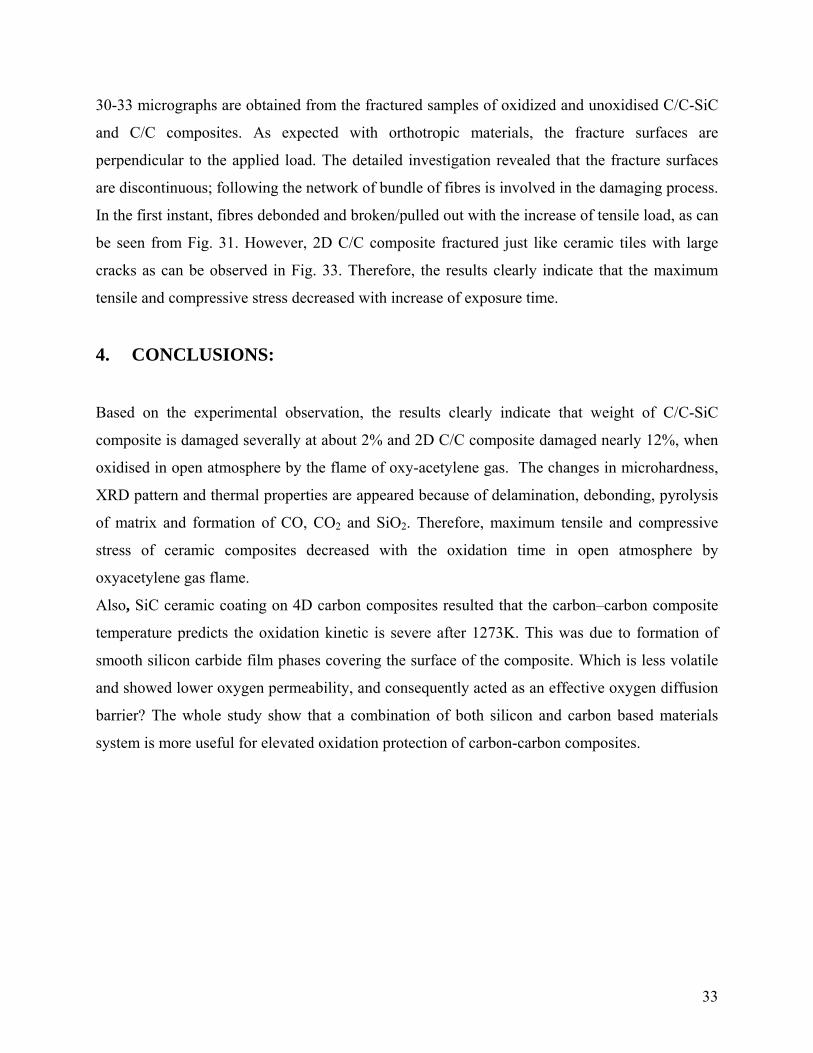
33
30-33 micrographs are obtained from the fractured samples of oxidized and unoxidised C/C-SiC
and C/C composites. As expected with orthotropic materials, the fracture surfaces are
perpendicular to the applied load. The detailed investigation revealed that the fracture surfaces
are discontinuous; following the network of bundle of fibres is involved in the damaging process.
In the first instant, fibres debonded and broken/pulled out with the increase of tensile load, as can
be seen from Fig. 31. However, 2D C/C composite fractured just like ceramic tiles with large
cracks as can be observed in Fig. 33. Therefore, the results clearly indicate that the maximum
tensile and compressive stress decreased with increase of exposure time.
4. CONCLUSIONS:
Based on the experimental observation, the results clearly indicate that weight of C/C-SiC
composite is damaged severally at about 2% and 2D C/C composite damaged nearly 12%, when
oxidised in open atmosphere by the flame of oxy-acetylene gas. The changes in microhardness,
XRD pattern and thermal properties are appeared because of delamination, debonding, pyrolysis
of matrix and formation of CO, CO2 and SiO2. Therefore, maximum tensile and compressive
stress of ceramic composites decreased with the oxidation time in open atmosphere by
oxyacetylene gas flame.
Also, SiC ceramic coating on 4D carbon composites resulted that the carbon–carbon composite
temperature predicts the oxidation kinetic is severe after 1273K. This was due to formation of
smooth silicon carbide film phases covering the surface of the composite. Which is less volatile
and showed lower oxygen permeability, and consequently acted as an effective oxygen diffusion
barrier? The whole study show that a combination of both silicon and carbon based materials
system is more useful for elevated oxidation protection of carbon-carbon composites.

34
5. REFERENCES:
1. Krnel K., Stadler Z. and Kosmac T. J., Eur. Ceram. Soc. 27 (2007) 1211–1216.
2. Inghels E., Lamon, J., J. of Materials Science, 26 (1991) 5411-5419.
3. Gac F.D. and Petrovic J.J. J., Am. Ceram. Soc. 68-8 (1985) C200–C201.
4. Jeng Y.L. and Laverina E.J. J., Mater. Sci. 29 (1994)2557–2571.
5. Gang F.Q., Jun L.H.,Hong S.X., Zhi L.K., Min H. and Dong S.G., Surface and
Coatings Technology, 201-6(2006)3082-3086.
6. Fan Z., Song Y., Li J., Liu L., Song J., Chen J., Zhai G. and Shi J., Carbon 41-
3(2003)429-436.
7. Kobayashi K, Miyazaki K, Ogawa I, Hagio T, Yoshida H, Materials &Design 9-1
(1988)10-21.
8. Piquero T., Vincent T., Vincent C. and Bouix J., Carbon 33-4(1995)455-467.
9. Paul F. B. Journal of the American Ceramic Society, 66- 8 (1983)C-120.
10. Taylor, R., Comprehensive composite materials, Elsevier science Ltd., Boston, (2000)
387-426.
11. Fitzer, E., Manocha, L.M., Carbon reinforcement and C/C composites, Springer-verlag,
Berlin, (1998).
12. Buckly, J.D., Edie, D.D., C-C materials and composites, Noyes publications, New
Jersey, (1993), 1-12.
13. Westwood, M.E., Webster, J.D., Day, R.J., Hayes F.H., Taylor, R., J. Mater Sci.
31(1996), 1389.
14. Heimann, D., Bill, J., Aldinger, F., Schanz, P., Gern, F.H., Krenkel, W., Kochendorfer,
R., Development of oxidation product Carbon/Carbon., Z Flugwiss Weltraum (1995); 19:
180-8.
15. Williams, J.C., Yurgartis, S.W., Moosbrugger, J.C., Interlaminar Shear fatigue damage
evaluation of 2D Carbon-Carbon composites, J Compos Mater (1996); 30(7): 785-800.
16. Arendts, F.J., Theuer, A., Maile, K., Kuhnle, J., Neuer, G., Brandt, R.,
Thermomechanical and Thermophysical properties of liquid Siliconized C/C-SiC, Z.
Flugwiss Weltraum, 1995; 19:189-96.
35
17. J Schulte-fischedick, J., Zern, A., Mayer, J., Ruhle, M., Frie, B.M., Krenkel, W.,
Kochenderfer, R., The morphology of SiC in C/C-SiC composites, Mater Sci Eng-A
(2002); 332: 146-52.
18. Roos, E., Maile, K., Lyutovich, A., Cusko, A., Udoh, A., (Cr-A) bilayer coating obtained
by ion assisted EB PVD on C/C-SiC composites and Ni based alloys, Surf Coat Technol,
(2002); 151-152; 429-33.
19. Srivastava, V.K., Maile, K., Klenk, A., High Velocity impact perforation on C/C-SiC
composites. High temperature-High pressure, (1999); 31: 487-97.
20. Arendts, F.J., Maile, K., Thermomechanicshes Verhalten Von C/C-SiC. Arebeits-und
Ergebnisbericht SFB (1998):259.

36
6. PUBLICATIONS:
i. V.K. Srivastava and S. Singh, Effect of gas flame on performance of C/C-SiC composites,
HTCMC-6, India Habitat Center, New Delhi, Sept. 2007 (Accepted).
ii. V. K. Srivastava, Oxidation behavior of ceramic composites in open atmosphere, 32nd Int.
Conf. & Exposition on Advanced Ceramic & Composites, Hilton Daytona Beach Resort Ocean
Center, Jan 27-Feb 1, 2008 (Submitted)
7. WORK SCHEDULE FOR 2nd YEAR:
Following work will be organized to get another set of the results during the second year.
*Ceramic composite will be exposed with the hot water, acid and hydrogen. Mechanical
properties of exposed composites will be obtained to describe the effect of above environments.
*Mechanical Characterization of lap joint of C/C-SiC and Ti alloy In this direction, we will
firstly prepare the 6 samples of titanium and 6 samples of C/C-SiC of (60×13×3) mm. The
surface of samples is first washed with washing powder to remove any foreign material, after
some time it will become dry. And again clean with acetone. We will prepare six pair of samples
of different type. In three samples araldite and hardener used as an adhesive in the ratio of 1:10
and in another three samples we will also add Si powder in araldite epoxy adhesive. In first
piece, the C/C-SiC and Ti sheet were joined; in second piece Ti and Ti were joined and in third
piece C/C-SiC and C/C-SiC were joined in the fashion of single lap joint. From these we will
study the mechanical characterization of different type of samples. We will study the property
and strength of joints under SEM and TEM.
* Simulation study will be carried out with the help of various computer programming. Finally
the analytical and experimental results will be correlated with each to find the variation in
results.
8. Grant required for second year:
Grant require for the completion of proposed research work is $ 23160.