Invertebrate bycatch from bottom trawls in the New Zealand EEZ

EEZ RV PRODUCTSEezTire T515 SYSTEM
WIRELESS TIRE PRESSURE AND TEMPERATURE MONITORING SYSTEM (TPMS)
Instruction ManualModel No: TM-515T22/SP
2 3
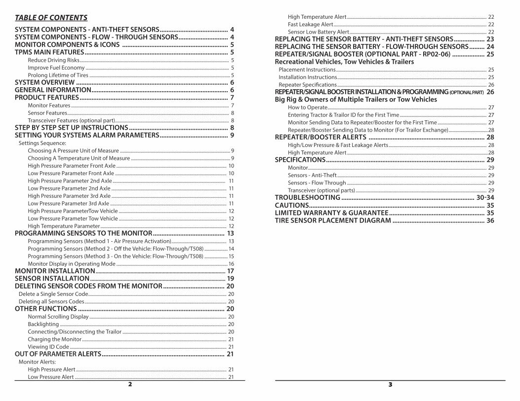
TABLE OF CONTENTSSYSTEM COMPONENTS - ANTI-THEFT SENSORS ........................................ 4 SYSTEM COMPONENTS - FLOW - THROUGH SENSORS ............................. 4MONITOR COMPONENTS & ICONS .............................................................. 5 TPMS MAIN FEATURES .................................................................................... 5 Reduce Driving Risks .......................................................................................................................... 5 Improve Fuel Economy ..................................................................................................................... 5 Prolong Lifetime of Tires ................................................................................................................... 5 SYSTEM OVERVIEW ......................................................................................... 6 GENERAL INFORMATION ................................................................................ 6 PRODUCT FEATURES ....................................................................................... 7 Monitor Features ................................................................................................................................. 7 Sensor Features .................................................................................................................................... 8 Transceiver Features (optional part) ............................................................................................. 8STEP BY STEP SET UP INSTRUCTIONS .......................................................... 8 SETTING YOUR SYSTEMS ALARM PARAMETERS ........................................ 9 Settings Sequence: Choosing A Pressure Unit of Measure .......................................................................................... 9 Choosing A Temperature Unit of Measure ................................................................................. 9 High Pressure Parameter Front Axle .......................................................................................... 10 Low Pressure Parameter Front Axle ........................................................................................... 10 High Pressure Parameter 2nd Axle ............................................................................................ 11 Low Pressure Parameter 2nd Axle .............................................................................................. 11 High Pressure Parameter 3rd Axle .............................................................................................. 11 Low Pressure Parameter 3rd Axle ............................................................................................... 11 High Pressure ParameterTow Vehicle ........................................................................................ 12 Low Pressure Parameter Tow Vehicle ........................................................................................ 12 High Temperature Parameter ....................................................................................................... 12PROGRAMMING SENSORS TO THE MONITOR .......................................... 13 Programming Sensors (Method 1 - Air Pressure Activation) ............................................. 13 Programming Sensors (Method 2 - Off the Vehicle: Flow-Through/T508) ................... 14 Programming Sensors (Method 3 - On the Vehicle: Flow-Through/T508) ................... 15 Monitor Display in Operating Mode ........................................................................................... 16MONITOR INSTALLATION ............................................................................................. 17 SENSOR INSTALLATION ................................................................................................. 19DELETING SENSOR CODES FROM THE MONITOR .................................... 20 Delete a Single Sensor Code ................................................................................................................. 20 Deleting all Sensors Codes .................................................................................................................... 20 OTHER FUNCTIONS ...................................................................................... 20 Normal Scrolling Display ................................................................................................................ 20 Backlighting ........................................................................................................................................ 20 Connecting/Disconnecting the Trailor ..................................................................................... 20 Charging the Monitor ...................................................................................................................... 21 Viewing ID Code ................................................................................................................................ 21 OUT OF PARAMETER ALERTS ........................................................................ 21 Monitor Alerts: High Pressure Alert ........................................................................................................................... 21 Low Pressure Alert ............................................................................................................................ 21
3
High Temperature Alert .................................................................................................................. 22 Fast Leakage Alert ............................................................................................................................. 22 Sensor Low Battery Alert ................................................................................................................ 22REPLACING THE SENSOR BATTERY - ANTI-THEFT SENSORS .................. 23 REPLACING THE SENSOR BATTERY - FLOW-THROUGH SENSORS ......... 24REPEATER/SIGNAL BOOSTER (OPTIONAL PART - RP02-06) ................... 25 Recreational Vehicles, Tow Vehicles & Trailers Placement Instructions ........................................................................................................................... 25 Installation Instructions .......................................................................................................................... 25 Repeater Specifications .......................................................................................................................... 26 REPEATER/SIGNAL BOOSTER INSTALLATION & PROGRAMMING (OPTIONAL PART) 26 Big Rig & Owners of Multiple Trailers or Tow Vehicles How to Operate .................................................................................................................................. 27 Entering Tractor & Trailor ID for the First Time ....................................................................... 27 Monitor Sending Data to Repeater/Booster for the First Time ........................................ 27 Repeater/Booster Sending Data to Monitor (For Trailor Exchange) ................................28 REPEATER/BOOSTER ALERTS .................................................................... 28 High/Low Pressure & Fast Leakage Alerts ................................................................................ 28 High Temperature Alert ...................................................................................................................28 SPECIFICATIONS ............................................................................................. 29 Monitor.................................................................................................................................................. 29 Sensors - Anti-Theft .......................................................................................................................... 29 Sensors - Flow Through .................................................................................................................. 29 Transceiver (optional parts) ........................................................................................................... 29 TROUBLESHOOTING .............................................................................. 30-34CAUTIONS....................................................................................................... 35 LIMITED WARRANTY & GUARANTEE ........................................................ 35 TIRE SENSOR PLACEMENT DIAGRAM ...................................................... 36
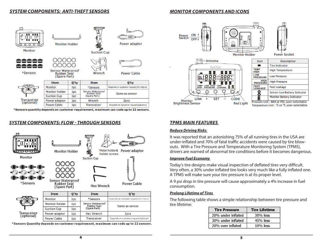
SYSTEM COMPONENTS: ANTI-THEFT SENSORS
4
SYSTEM COMPONENTS: FLOW - THROUGH SENSORS
MONITOR COMPONENTS AND ICONS
TPMS MAIN FEATURES Reduce Driving Risks
It was reported that an astonishing 75% of all running tires in the USA are under-inflated and 70% of fatal traffic accidents were caused by tire blow-outs. With a Tire Pressure and Temperature Monitoring System (TPMS), drivers are warned of abnormal tire conditions before it becomes dangerous. Improve Fuel Economy
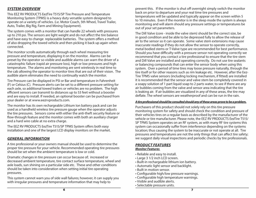
Today’s tire designs make visual inspection of deflated tires very difficult. Very often, a 30% under inflated tire looks very much like a fully inflated one. A TPMS will make sure your tire pressure is at its proper level. A 9 psi drop in tire pressure will cause approximately a 4% increase in fuel consumption. Prolong Lifetime of Tires
The following table shows a simple relationship between tire pressure and tire lifetime:
5
6 7
SYSTEM OVERVIEWThis EEZ RV PRODUCTS EezTire T515/SP Tire Pressure and Temperature Monitoring System (TPMS) is a heavy duty versatile system designed to operate on a variety of vehicles. (i.e. Motor Coach, 5th Wheel, Travel Trailer, Auto, Trailer, Big Rig, Farm and Mining Equipment).The system comes with a monitor that can handle 22 wheels with pressures up to 210 psi. The sensors are light weight and do not affect the tire balance and have easy to change replaceable batteries. The system offers a method of also dropping the towed vehicle and then picking it back up again when connected. The monitor scrolls automatically through each wheel measuring tire pressure and temperature, displaying it on the monitor. Alarms can be preset by the operator so visible and audible alarms can warn the driver of a catastrophic failure (rapid air pressure loss), high or low pressures and high temperature. The alarms and monitoring are sent wirelessly in real time to the cab allowing the operator to monitor tires that are out of their vision. The audible alarm eliminates the need to continually watch the monitor. Tire Pressure can be displayed in PSI or Bar and temperature in Fahrenheit (F) or Celsius (C). Pressure alerts can be set to a different pressure setting for each axle, so additional towed trailers or vehicles are no problem. The high efficient sensors can transmit to distances up to 53 feet without a booster and are easy to install. If needed, an optional booster can be purchased from your dealer or at www.eezrvproducts.com.The monitor has its own rechargeable Lithium Ion battery pack and can be used as a handheld wireless tire pressure gauge when the operator adjusts the tire pressures. Sensors come with either the anti-theft security feature or flow-through feature and the monitor comes with both an auxiliary charger and a hard wire cable at no extra charge.The EEZ RV PRODUCTS EezTire T515/SP TPMS System offers both easy installation and one of the largest LCD display monitors on the market.
GENERAL INFORMATIONA tire professional or your owners manual should be used to determine the proper tire pressure for your vehicle. Recommended operating tire pressures should be set when the ambient temperature is low or cold. Dramatic changes in tire pressure can occur because of; increased or decreased ambient temperature, tire contact surface temperature, wheel and axle loads, sun shining on a particular side etc. These and other conditions should be taken into consideration when setting initial tire operating pressures. This system cannot warn you of side wall failures; however, it can supply you with irregular pressures and temperature information that may help to
prevent this. If the monitor is shut off overnight simply switch the monitor back on prior to departure and your real time tire pressures and temperatures will be updated and typically appear on the screen within 5 to 10 minutes. Even if the monitor is in the sleep mode the system is always monitoring and will alarm should any pressure settings or temperatures be out of your set parameters. The Dill Valve (core - inside the valve stem) should be the correct size, be in good condition and be able to be depressed fully to allow the release of air to the sensor so it can operate. Some valve stem extensions may cause inaccurate readings if they do not allow the sensor to operate correctly, metal bodied stems or T-Valve type are recommended for best performance. Should you have difficulty with a pressure sensor not operating correctly we recommend that you contact a tire professional to ensure that the tire stem and Dill Valve are installed and operating correctly. Do not use tire sealants or balancing compounds that can enter the sensor body when using this system. Over a period of time tires may loose pressure naturally, through the tire itself or for other reasons such as rim leakage etc. However, after the Eez-Tire TPMS valve sensors (including locking mechanism, if fitted) are installed it is recommended that the sensor and valve stem be completely covered in a soapy solution of 1 part liquid soap to 2 parts water, to see if there are any air bubbles coming from the valve and sensor area indicating that the tire is leaking air. If air bubbles are visualized in any of these areas, the tire may deflate. The wheel sensors are weatherproof and can be run in the rain.
A tire professional should be consulted should any of these areas prove to be a problem.
Purchasers of this product should not solely rely on this tire pressure monitoring system for safety and should check the condition and pressure of their vehicles tires on a regular basis as described by the manufacturer of the vehicle or tire manufacturer. Please note, the EEZ RV PRODUCTS EezTire T515/SP TPMS System operates on an RF system, as with many RF tire systems this system can occasionally suffer from interference depending on the systems location; thus causing the system to be inaccurate or not operate at all. Tire pressures and temperatures are not the only things that can affect tire safety; we suggest daily visual inspections and periodic checks by tire professionals.
PRODUCT FEATURES Monitor Features
• Reliable and easy to install. • Large 3 1/2 inch LCD screen. • Built-in rechargeable lithium ion battery. • Automatic light sensor and backlight. • Built in motion sensor.• Configurable high/low pressure warnings. • Configurable high temperature warnings. • Visible and audible alerts. • Selectable pressure units.
8 9
• Can monitor in either standard or metric measurements (psi or bar/F or C) • Monitors up to 22 tires maximum. • Long range between sensors and monitor. • Per axle measurements can be configured on the tractor. Sensor Features
• Reliable cap sensors, easy to install. • Water resistant. • Replaceable sensor batteries. • Fast leakage alert. • Individually coded sensors. • Anti-theft or flow-through design. Transceiver Features (optional part) • Maintains signal stability. • Records sensor !D, trailer !D and tire pressure and temperature limits. • Supports truck and trailer exchange. • Transferable trailer sensor data between monitor and transceiver. • Visible and audible alerts. • Fixed alert for high temperature (194°F)
SYSTEM SETUP This portion is designed to make the set-up of your new EEZ RV PRODUCTS EezTire T515/SP TPMS System easier and faster.
Much of the information contained in this manual is found through real life experience using the system and passed on to hopefully make the use of the system easier for you.
Please read through the guide completely prior to starting. Complete set-up should take approximately 20 minutes.
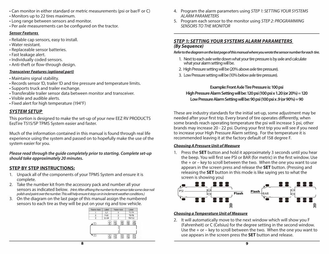
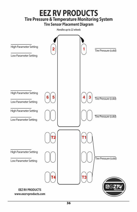
STEP BY STEP INSTRUCTIONS:1. Unpack all of the components of your TPMS System and ensure it is complete.2. Take the number kit from the accessory pack and number all your sensors as indicated below. (Hint: After affixing the number to the sensor take some clear nail polish and paint over the number. This will help ensure it stays on in inclement weather conditions.)3. On the diagram on the last page of this manual assign the numbered sensors to each tire as they will be put on your rig and tow vehicle.
4. Program the alarm parameters using STEP 1: SETTING YOUR SYSTEMS ALARM PARAMETERS5. Program each sensor to the monitor using STEP 2: PROGRAMMING SENSORS TO THE MONITOR
STEP 1: SETTING YOUR SYSTEMS ALARM PARAMETERS (By Sequence)Refer to the diagram on the last page of this manual where you wrote the sensor number for each tire.
1. Next to each axle write down what your tire pressure is by axle and calculate what your alarm setting will be. 2. High Pressure setting will be (20% above axle tire pressure). 3. Low Pressure setting will be (10% below axle tire pressure).
Example: Front Axle Tire Pressure is: 100 psiHigh Pressure Alarm Setting will be: 120 psi (100 psi x 1.20 (or 20%) = 120
Low Pressure Alarm Setting will be: 90 psi (100 psi x .9 (or 90%) = 90
These are industry standards for the initial set-up, some adjustment may be needed after your first trip. Every brand of tire operates differently, when some brands reach operating temperature the psi will increase 5 psi, other brands may increase 20 - 22 psi. During your first trip you will see if you need to increase your High Pressure Alarm setting. For the temperature it is recommended leaving it at the factory default of 158 degree F.
Choosing A Pressure Unit of Measure
1. Press the SET button and hold it approximately 3 seconds until you hear the beep. You will first see PSI or BAR (for metric) in the first window. Use the + or – key to scroll between the two. When the one you want to use appears in the screen press and release the SET button. (Pressing and releasing the SET button in this mode is like saying yes to what the screen is showing you)
Choosing a Temperature Unit of Measure2. It will automatically move to the next window which will show you F (Fahrenheit) or C (Celsius) for the degree setting in the second window. Use the + or – key to scroll between the two. When the one you want to use appears in the screen press the SET button and release.
10 11
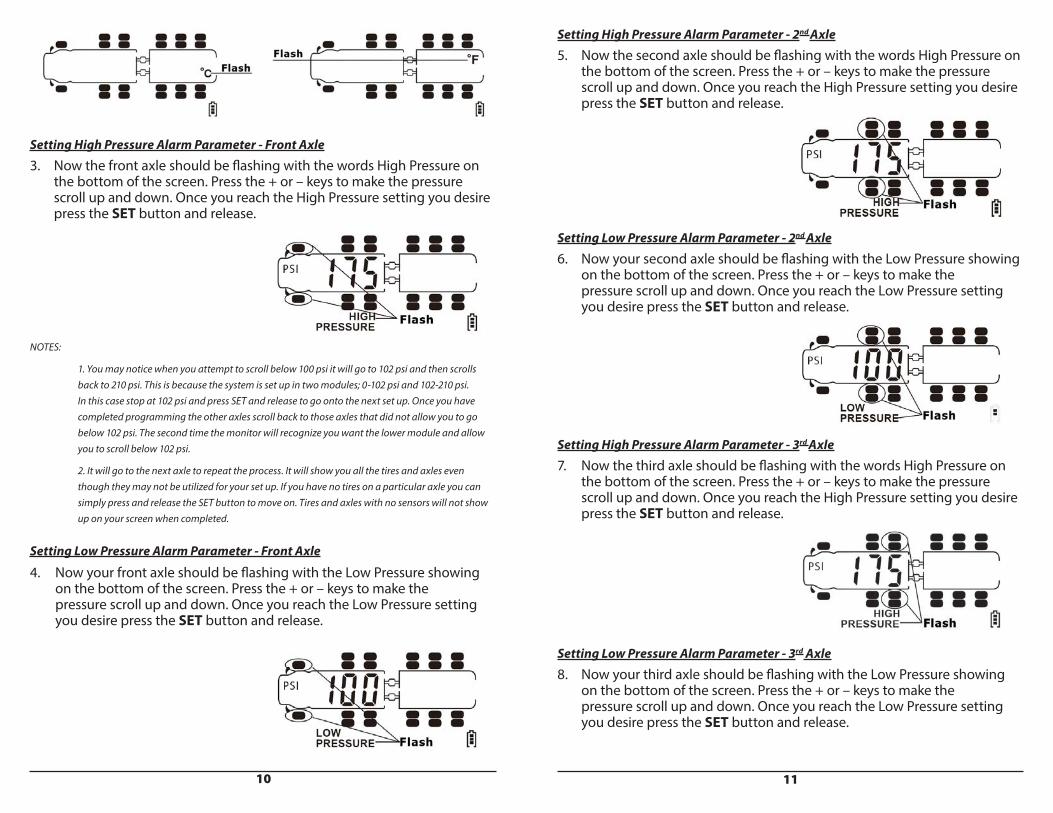
Setting High Pressure Alarm Parameter - Front Axle3. Now the front axle should be flashing with the words High Pressure on the bottom of the screen. Press the + or – keys to make the pressure scroll up and down. Once you reach the High Pressure setting you desire press the SET button and release.
NOTES:
1. You may notice when you attempt to scroll below 100 psi it will go to 102 psi and then scrolls back to 210 psi. This is because the system is set up in two modules; 0-102 psi and 102-210 psi. In this case stop at 102 psi and press SET and release to go onto the next set up. Once you have completed programming the other axles scroll back to those axles that did not allow you to go below 102 psi. The second time the monitor will recognize you want the lower module and allow you to scroll below 102 psi.
2. It will go to the next axle to repeat the process. It will show you all the tires and axles even though they may not be utilized for your set up. If you have no tires on a particular axle you can simply press and release the SET button to move on. Tires and axles with no sensors will not show up on your screen when completed.
Setting Low Pressure Alarm Parameter - Front Axle
4. Now your front axle should be flashing with the Low Pressure showing on the bottom of the screen. Press the + or – keys to make the pressure scroll up and down. Once you reach the Low Pressure setting you desire press the SET button and release.
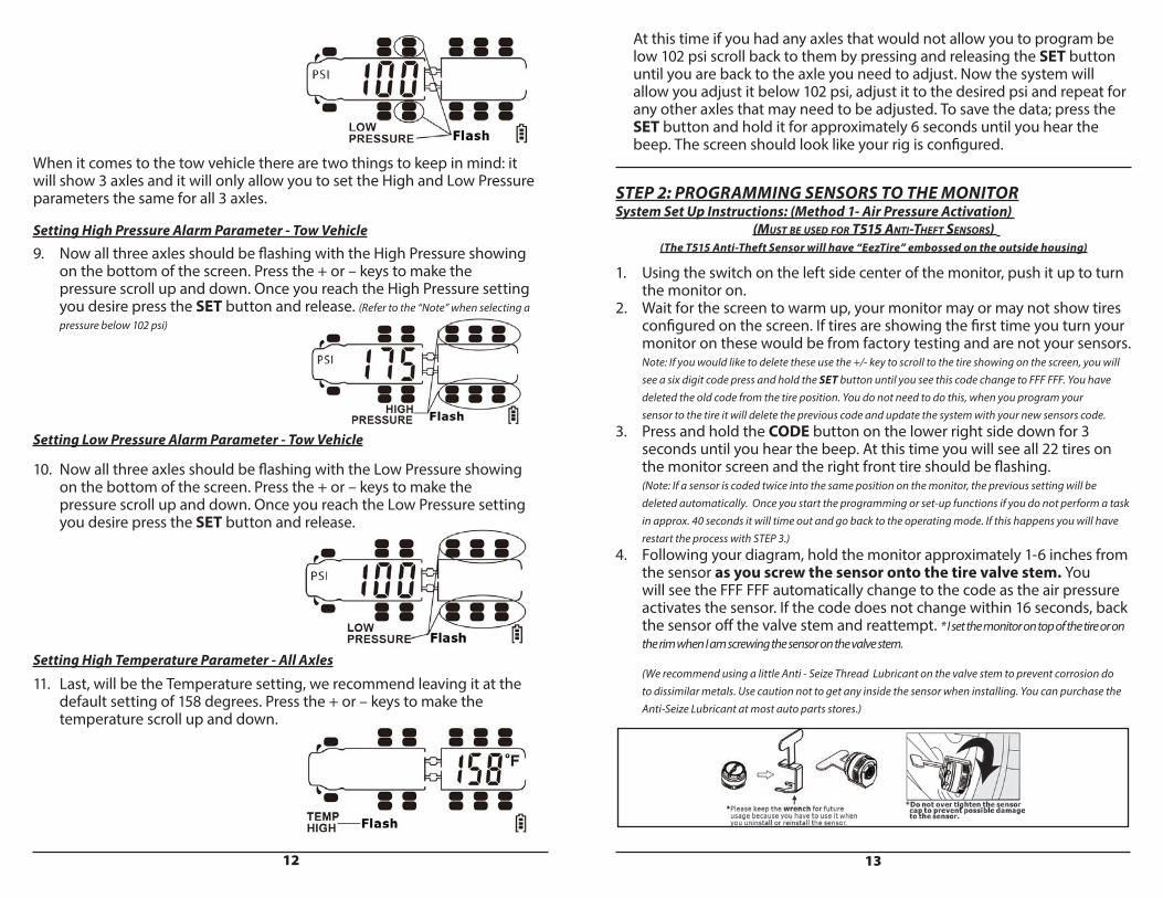
Setting High Pressure Alarm Parameter - 2nd Axle5. Now the second axle should be flashing with the words High Pressure on the bottom of the screen. Press the + or – keys to make the pressure scroll up and down. Once you reach the High Pressure setting you desire press the SET button and release.
Setting Low Pressure Alarm Parameter - 2nd Axle6. Now your second axle should be flashing with the Low Pressure showing on the bottom of the screen. Press the + or – keys to make the pressure scroll up and down. Once you reach the Low Pressure setting you desire press the SET button and release.
Setting High Pressure Alarm Parameter - 3rd Axle7. Now the third axle should be flashing with the words High Pressure on the bottom of the screen. Press the + or – keys to make the pressure scroll up and down. Once you reach the High Pressure setting you desire press the SET button and release.
Setting Low Pressure Alarm Parameter - 3rd Axle8. Now your third axle should be flashing with the Low Pressure showing on the bottom of the screen. Press the + or – keys to make the pressure scroll up and down. Once you reach the Low Pressure setting you desire press the SET button and release.
12 13
When it comes to the tow vehicle there are two things to keep in mind: it will show 3 axles and it will only allow you to set the High and Low Pressure parameters the same for all 3 axles.
Setting High Pressure Alarm Parameter - Tow Vehicle9. Now all three axles should be flashing with the High Pressure showing on the bottom of the screen. Press the + or – keys to make the pressure scroll up and down. Once you reach the High Pressure setting you desire press the SET button and release. (Refer to the “Note” when selecting a pressure below 102 psi)
Setting Low Pressure Alarm Parameter - Tow Vehicle
10. Now all three axles should be flashing with the Low Pressure showing on the bottom of the screen. Press the + or – keys to make the pressure scroll up and down. Once you reach the Low Pressure setting you desire press the SET button and release.
Setting High Temperature Parameter - All Axles
11. Last, will be the Temperature setting, we recommend leaving it at the default setting of 158 degrees. Press the + or – keys to make the temperature scroll up and down.
At this time if you had any axles that would not allow you to program be low 102 psi scroll back to them by pressing and releasing the SET button until you are back to the axle you need to adjust. Now the system will allow you adjust it below 102 psi, adjust it to the desired psi and repeat for any other axles that may need to be adjusted. To save the data; press the SET button and hold it for approximately 6 seconds until you hear the beep. The screen should look like your rig is configured.
STEP 2: PROGRAMMING SENSORS TO THE MONITORSystem Set Up Instructions: (Method 1- Air Pressure Activation)
(MUST BE USED FOR T515 ANTI-THEFT SENSORS) (The T515 Anti-Theft Sensor will have “EezTire” embossed on the outside housing)
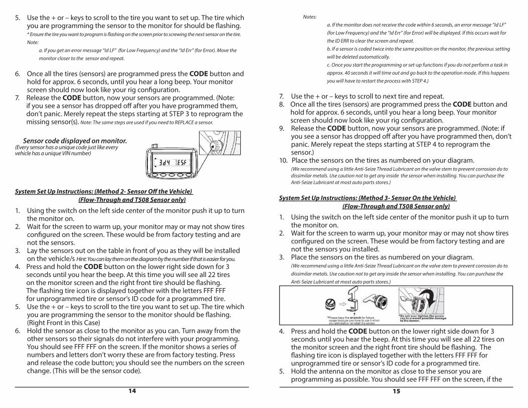
1. Using the switch on the left side center of the monitor, push it up to turn the monitor on.2. Wait for the screen to warm up, your monitor may or may not show tires configured on the screen. If tires are showing the first time you turn your monitor on these would be from factory testing and are not your sensors. Note: If you would like to delete these use the +/- key to scroll to the tire showing on the screen, you will see a six digit code press and hold the SET button until you see this code change to FFF FFF. You have deleted the old code from the tire position. You do not need to do this, when you program your sensor to the tire it will delete the previous code and update the system with your new sensors code.3. Press and hold the CODE button on the lower right side down for 3 seconds until you hear the beep. At this time you will see all 22 tires on the monitor screen and the right front tire should be flashing. (Note: If a sensor is coded twice into the same position on the monitor, the previous setting will be deleted automatically. Once you start the programming or set-up functions if you do not perform a task in approx. 40 seconds it will time out and go back to the operating mode. If this happens you will have restart the process with STEP 3.)4. Following your diagram, hold the monitor approximately 1-6 inches from the sensor as you screw the sensor onto the tire valve stem. You will see the FFF FFF automatically change to the code as the air pressure activates the sensor. If the code does not change within 16 seconds, back the sensor off the valve stem and reattempt. * I set the monitor on top of the tire or on the rim when I am screwing the sensor on the valve stem.
(We recommend using a little Anti - Seize Thread Lubricant on the valve stem to prevent corrosion do to dissimilar metals. Use caution not to get any inside the sensor when installing. You can purchase the Anti-Seize Lubricant at most auto parts stores.)
14 15
5. Use the + or – keys to scroll to the tire you want to set up. The tire which you are programming the sensor to the monitor for should be flashing. * Ensure the tire you want to program is flashing on the screen prior to screwing the next sensor on the tire. Note: a. If you get an error message “Id LF” (for Low Frequency) and the “Id Err” (for Error). Move the monitor closer to the sensor and repeat. 6. Once all the tires (sensors) are programmed press the CODE button and hold for approx. 6 seconds, until you hear a long beep. Your monitor screen should now look like your rig configuration.7. Release the CODE button, now your sensors are programmed. (Note: if you see a sensor has dropped off after you have programmed them, don’t panic. Merely repeat the steps starting at STEP 3 to reprogram the missing sensor(s). Note: The same steps are used if you need to REPLACE a sensor.
Sensor code displayed on monitor. (Every sensor has a unique code just like every vehicle has a unique VIN number)
System Set Up Instructions: (Method 2- Sensor Off the Vehicle) (Flow-Through and T508 Sensor only)
1. Using the switch on the left side center of the monitor push it up to turn the monitor on.2. Wait for the screen to warm up, your monitor may or may not show tires configured on the screen. These would be from factory testing and are not the sensors.3. Lay the sensors out on the table in front of you as they will be installed on the vehicle/s Hint: You can lay them on the diagram by the number if that is easier for you.4. Press and hold the CODE button on the lower right side down for 3 seconds until you hear the beep. At this time you will see all 22 tires on the monitor screen and the right front tire should be flashing. The flashing tire icon is displayed together with the letters FFF FFF for unprogrammed tire or sensor’s ID code for a programmed tire. 5. Use the + or – keys to scroll to the tire you want to set up. The tire which you are programming the sensor to the monitor should be flashing. (Right Front in this Case) 6. Hold the sensor as close to the monitor as you can. Turn away from the other sensors so their signals do not interfere with your programming. You should see FFF FFF on the screen. If the monitor shows a series of numbers and letters don’t worry these are from factory testing. Press and release the code button; you should see the numbers on the screen change. (This will be the sensor code).
Notes: a. If the monitor does not receive the code within 6 seconds, an error message “Id LF” (for Low Frequency) and the “Id Err” (for Error) will be displayed. If this occurs wait for the ID ERR to clear the screen and repeat. b. If a sensor is coded twice into the same position on the monitor, the previous setting will be deleted automatically. c. Once you start the programming or set-up functions if you do not perform a task in approx. 40 seconds it will time out and go back to the operation mode. If this happens you will have to restart the process with STEP 4.)
7. Use the + or – keys to scroll to next tire and repeat. 8. Once all the tires (sensors) are programmed press the CODE button and hold for approx. 6 seconds, until you hear a long beep. Your monitor screen should now look like your rig configuration.9. Release the CODE button, now your sensors are programmed. (Note: if you see a sensor has dropped off after you have programmed then, don’t panic. Merely repeat the steps starting at STEP 4 to reprogram the sensor.)10. Place the sensors on the tires as numbered on your diagram. (We recommend using a little Anti-Seize Thread Lubricant on the valve stem to prevent corrosion do to dissimilar metals. Use caution not to get any inside the sensor when installing. You can purchase the Anti-Seize Lubricant at most auto parts stores.)
System Set Up Instructions: (Method 3- Sensor On the Vehicle) (Flow-Through and T508 Sensor only)
1. Using the switch on the left side center of the monitor push it up to turn the monitor on.2. Wait for the screen to warm up, your monitor may or may not show tires configured on the screen. These would be from factory testing and are not the sensors you installed.3. Place the sensors on the tires as numbered on your diagram. (We recommend using a little Anti-Seize Thread Lubricant on the valve stem to prevent corrosion do to dissimilar metals. Use caution not to get any inside the sensor when installing. You can purchase the Anti-Seize Lubricant at most auto parts stores.)
4. Press and hold the CODE button on the lower right side down for 3 seconds until you hear the beep. At this time you will see all 22 tires on the monitor screen and the right front tire should be flashing. The flashing tire icon is displayed together with the letters FFF FFF for unprogrammed tire or sensor’s ID code for a programmed tire. 5. Hold the antenna on the monitor as close to the sensor you are programming as possible. You should see FFF FFF on the screen, if the
16 17
monitor shows a series of numbers and letters don’t worry this is most likely from factory testing. Press and release the CODE button; you should see the numbers on the screen change. (This will be the sensor code). If you see Id Err (Error) or Id LF (Low Frequency) press and release the CODE button again.
Notes: a. If the monitor does not receive the code within 6 seconds, an error message “Id LF” (for Low Frequency) and the “Id Err” (for Error) will be displayed. A double-beep will be issued and the red light goes out. Move the sensor closer to the monitor and repeat. b. If a sensor is coded twice into the same position on the monitor, the previous setting will be deleted automatically. c. Once you start the programming or set-up functions if you do not perform a task in approx. 40 seconds it will time out and go back to the operation mode. If this happens you will have restart the process with STEP 4.)
6. Use the + or – keys to scroll to next tire and repeat. 7. Once all the tires (sensors) are programmed press the CODE button and hold for approx. 6 seconds, until you hear a long beep. Your monitor screen should now look like your rig configuration.8. Release the CODE button, now your sensors are programmed. (Note: if you see a sensor has dropped off after you have programmed them, don’t panic. Merely repeat the steps starting at STEP 4 to reprogram the sensor.)
YOUR SYSTEM IS NOW SET-UP AND READY FOR USE
MONITOR DISPLAY IN OPERATING MODE
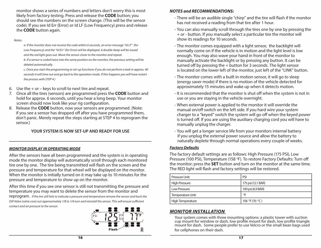
After the sensors have all been programmed and the system is in operating mode the monitor display will automatically scroll through each monitored tire one by one. The tire being transmitted will flash on the screen and the pressure and temperature for that wheel will be displayed on the monitor. When the monitor is initially turned on it may take up to 10 minutes for the pressure and temperature to show up on the monitor. After this time if you see one sensor is still not transmitting the pressure and temperature you may want to delete the sensor from the monitor and reprogram. If the tire still fails to indicate a pressure and temperature remove the sensor and back the Dill Valve (valve core) out approximately 1/8 to 1/4 turn and reinstall the sensor. This will ensure sufficient contact and air pressure to the sensor.
NOTES and RECOMMENDATIONS: - There will be an audible single “chirp” and the tire will flash if the monitor has not received a reading from that tire after 1 hour. - You can also manually scroll through the tires one by one by pressing the + or - button. If you manually select a particular tire the monitor will show its readings for 10 seconds. - The monitor comes equipped with a light sensor, the backlight will normally come on if the vehicle is in motion and the light level is low enough. You may also wave your hand in front of the monitor to manually activate the backlight or by pressing any button. It can be turned off by pressing the + button for 3 seconds. The light sensor is located on the lower left of the monitor, just left of the “LINK” button. - The monitor comes with a built in motion sensor, it will go to sleep (energy saver mode) if there is no motion of the vehicle detected for approximately 15 minutes and wake up when it detects motion. - It is recommended that the monitor is shut off when the system is not in use or you are staying in the vehicle overnight. - When external power is applied to the monitor it will override the manual on/off switch on the left side. If you hard wire your system charger to a “keyed” switch the system will go off when the keyed power is turned off. If you are using the auxiliary charging cord you will have to manually unplug the charger. - You will get a longer service life from your monitors internal battery if you unplug the external power source and allow the battery to naturally deplete through normal operations every couple of weeks. Factory Defaults
The factory default settings are as follows: High Pressure (175 PSI), Low Pressure (100 PSI), Temperature (158 oF). To restore Factory Defaults: Turn off the monitor; press the SET button and turn on the monitor at the same time. The RED light will flash and factory settings will be restored.
Pressure Unit: PSI
High Pressure: 175 psi (12.1 BAR)
Low Pressure: 100 psi (6.9 BAR)
Temperature Unit: OF
High Temperature: 158 OF (70 OC )
MONITOR INSTALLATION Your system comes with three mounting options: a plastic tower with suction cup mount for window or dash, low profile mount for dash, low profile triangle mount for dash. Some people prefer to use Velcro or the small bean bags used for cellphones on their dash.
18 19
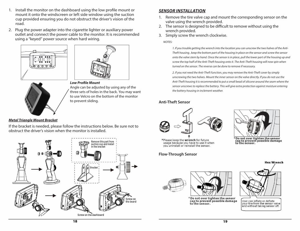
1. Install the monitor on the dashboard using the low profile mount or mount it onto the windscreen or left side window using the suction cup provided ensuring you do not obstruct the driver’s vision of the road. 2. Plug the power adapter into the cigarette lighter or auxiliary power outlet and connect the power cable to the monitor. It is recommended using a “keyed” power source when hard wiring.
Metal Triangle Mount Bracket
If the bracket is needed, please follow the instructions below. Be sure not to obstruct the driver’s vision when the monitor is installed.
Low Profile MountAngle can be adjusted by using any of the three sets of holes in the back. You may want to use Velcro on the bottom of the monitor to prevent sliding.
SENSOR INSTALLATION1. Remove the tire valve cap and mount the corresponding sensor on the valve using the wrench provided. 2. The sensor is designed to be difficult to remove without using the wrench provided. 3. Simply screw the wrench clockwise. NOTES:
1. If you trouble getting the wrench into the location you can unscrew the two halves of the Anti- Theft housing , keep the bottom part of the housing in place on the sensor and screw the sensor onto the valve stem by hand. Once the sensor is in place, pull the lower part of the housing up and screw the top half of the Anti-Theft housing onto it. The Anti-Theft housing will now spin when turned on the sensor. The reverse can be done to remove if necessary.
2. If you not need the Anti-Theft function, you may remove the Anti-Theft cover by simply unscrewing the two halves. Mount the inner sensor on the valve directly. If you do not use the Anti-Theft housing it is recommended to put a small bead of silicone around the seam where the sensor unscrews to replace the battery. This will give extra protection against moisture entering the battery housing in inclement weather.
Anti-Theft Sensor
Flow-Through Sensor
20 21
DELETING A SINGLE SENSOR ID1. In standby mode, press and hold the CODE button for 3 seconds, release it after the beep to enter the coding mode. A flashing tire icon and ID code are displayed. Press the + or - button to select the desired tire.2. Press and hold the SET button for 3 seconds. A double-beep sound will be issued after the sensor code is deleted successfully. If no further action is made after 3 minutes, the system will return to standby mode automatically. To return to standby mode immediately, press and hold the CODE button for 3 seconds until a beep is issued.
DELETING ALL SENSORS ID
1. In standby mode, press the CODE button to enter the review ID mode. A tire icon and sensor’s ID code will flash.2. Press and hold the LINK button for 3 seconds. During this period, a double-beep will be issued. The message DEL ALL will display on the monitor.3. Press the SET button to confirm the delete operation or press the CODE button to cancel. If no further action is made after 3 minutes, the operation is automatically cancelled and the system will return to standby mode.
OTHER FUNCTIONSNormal Scrolling Display During normal operation, the monitor scrolls through and displays the tires one by one for approximately 6 seconds. An audible single chirp will be issued if one of the sensor data is not received by the monitor for more than 60 minutes. You can manually scroll through and select the tire by pressing the + or - button. A manually selected tire will be displayed for 10 seconds.
Backlight and Motion Sensor The monitor has a built in light and motion sensor. The backlight turns on when it detects the vehicle is in motion and when it is dark enough or you may wave your hand in front of the monitor to activate the it. The moni-tor will enter sleep mode to conserve battery life if the motion sensor does not detect motion for 15 minutes. It will activate when it detects the vehicle is moving again or other motion. Press any button on the monitor to turn on the backlight manually, to turn it off, press and hold the + button for 3 seconds.Connecting/Disconnecting a Tow Vehicle or Trailer (Drop image from the screen) When the tow vehicle or trailer is not connecting to the coach or tractor, press the LINK and - buttons at the same time, the tow vehicle or trailer and its tire icons will be removed temporarily. Press the LINK and + buttons at the same time, the tow vehicle or trailer and its tire icons will re-appear.
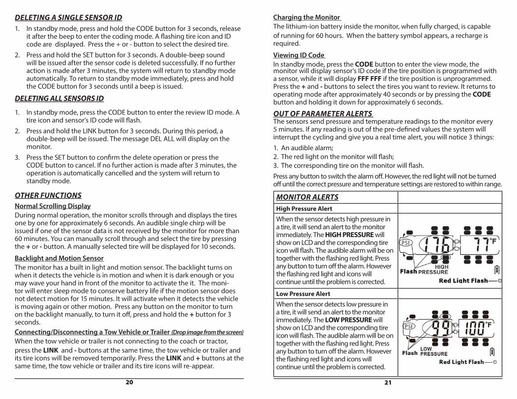
MONITOR ALERTSHigh Pressure AlertWhen the sensor detects high pressure in a tire, it will send an alert to the monitor immediately. The HIGH PRESSURE will show on LCD and the corresponding tire icon will flash. The audible alarm will be on together with the flashing red light. Press any button to turn off the alarm. However the flashing red light and icons will continue until the problem is corrected.
Low Pressure AlertWhen the sensor detects low pressure in a tire, it will send an alert to the monitor immediately. The LOW PRESSURE will show on LCD and the corresponding tire icon will flash. The audible alarm will be on together with the flashing red light. Press any button to turn off the alarm. However the flashing red light and icons will continue until the problem is corrected.
Charging the Monitor The lithium-ion battery inside the monitor, when fully charged, is capable of running for 60 hours. When the battery symbol appears, a recharge is required.
Viewing ID Code In standby mode, press the CODE button to enter the view mode, the monitor will display sensor’s ID code if the tire position is programmed with a sensor, while it will display FFF FFF if the tire position is unprogrammed. Press the + and - buttons to select the tires you want to review. It returns to operating mode after approximately 40 seconds or by pressing the CODE button and holding it down for approximately 6 seconds.
OUT OF PARAMETER ALERTS The sensors send pressure and temperature readings to the monitor every 5 minutes. If any reading is out of the pre-defined values the system will interrupt the cycling and give you a real time alert, you will notice 3 things: 1. An audible alarm; 2. The red light on the monitor will flash; 3. The corresponding tire on the monitor will flash. Press any button to switch the alarm off. However, the red light will not be turned off until the correct pressure and temperature settings are restored to within range.
22 23
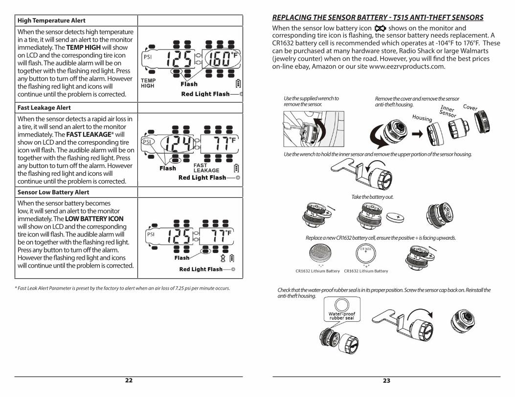
High Temperature Alert
When the sensor detects high temperature in a tire, it will send an alert to the monitor immediately. The TEMP HIGH will show on LCD and the corresponding tire icon will flash. The audible alarm will be on together with the flashing red light. Press any button to turn off the alarm. However the flashing red light and icons will continue until the problem is corrected.
Fast Leakage Alert
When the sensor detects a rapid air loss in a tire, it will send an alert to the monitor immediately. The FAST LEAKAGE* will show on LCD and the corresponding tire icon will flash. The audible alarm will be on together with the flashing red light. Press any button to turn off the alarm. However the flashing red light and icons will continue until the problem is corrected. Sensor Low Battery Alert
When the sensor battery becomes low, it will send an alert to the monitor immediately. The LOW BATTERY ICON will show on LCD and the corresponding tire icon will flash. The audible alarm will be on together with the flashing red light. Press any button to turn off the alarm. However the flashing red light and icons will continue until the problem is corrected.
* Fast Leak Alert Parameter is preset by the factory to alert when an air loss of 7.25 psi per minute occurs.
REPLACING THE SENSOR BATTERY - T515 ANTI-THEFT SENSORSWhen the sensor low battery icon shows on the monitor and corresponding tire icon is flashing, the sensor battery needs replacement. A CR1632 battery cell is recommended which operates at -104°F to 176°F. These can be purchased at many hardware store, Radio Shack or large Walmarts (jewelry counter) when on the road. However, you will find the best prices on-line ebay, Amazon or our site www.eezrvproducts.com.
Use the supplied wrench to remove the sensor.
Remove the cover and remove the sensor anti-theft housing.
Use the wrench to hold the inner sensor and remove the upper portion of the sensor housing.
Take the battery out.
Replace a new CR1632 battery cell, ensure the positive + is facing upwards.
Check that the water-proof rubber seal is in its proper position. Screw the sensor cap back on. Reinstall the anti-theft housing.
24 25
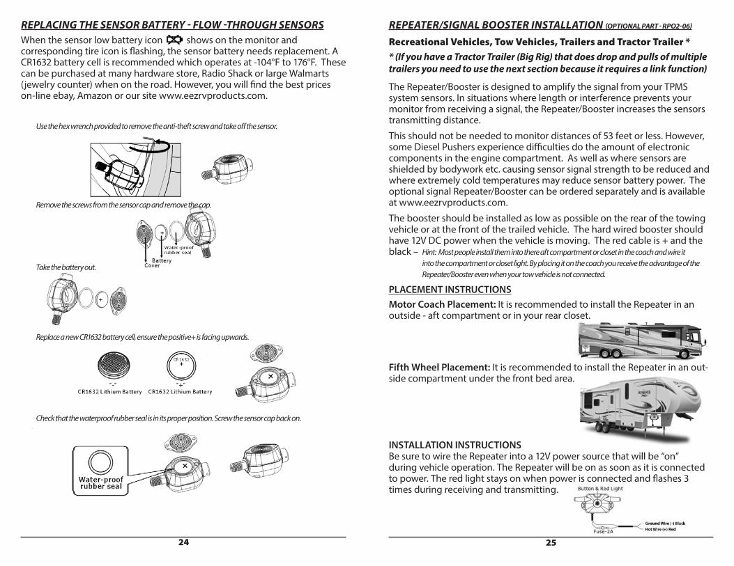
REPLACING THE SENSOR BATTERY - FLOW -THROUGH SENSORSWhen the sensor low battery icon shows on the monitor and corresponding tire icon is flashing, the sensor battery needs replacement. A CR1632 battery cell is recommended which operates at -104°F to 176°F. These can be purchased at many hardware store, Radio Shack or large Walmarts (jewelry counter) when on the road. However, you will find the best prices on-line ebay, Amazon or our site www.eezrvproducts.com.
Use the hex wrench provided to remove the anti-theft screw and take off the sensor.
Remove the screws from the sensor cap and remove the cap.
Take the battery out.
Replace a new CR1632 battery cell, ensure the positive+ is facing upwards.
Check that the waterproof rubber seal is in its proper position. Screw the sensor cap back on.
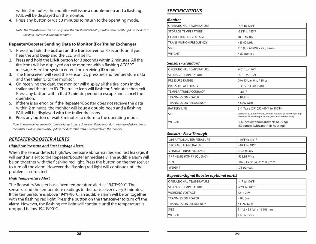
REPEATER/SIGNAL BOOSTER INSTALLATION (OPTIONAL PART - RPO2-06)
Recreational Vehicles, Tow Vehicles, Trailers and Tractor Trailer * * (If you have a Tractor Trailer (Big Rig) that does drop and pulls of multiple trailers you need to use the next section because it requires a link function)
The Repeater/Booster is designed to amplify the signal from your TPMS system sensors. In situations where length or interference prevents your monitor from receiving a signal, the Repeater/Booster increases the sensors transmitting distance.This should not be needed to monitor distances of 53 feet or less. However, some Diesel Pushers experience difficulties do the amount of electronic components in the engine compartment. As well as where sensors are shielded by bodywork etc. causing sensor signal strength to be reduced and where extremely cold temperatures may reduce sensor battery power. The optional signal Repeater/Booster can be ordered separately and is available at www.eezrvproducts.com.The booster should be installed as low as possible on the rear of the towing vehicle or at the front of the trailed vehicle. The hard wired booster should have 12V DC power when the vehicle is moving. The red cable is + and the black – Hint: Most people install them into there aft compartment or closet in the coach and wire it into the compartment or closet light. By placing it on the coach you receive the advantage of the Repeater/Booster even when your tow vehicle is not connected.
PLACEMENT INSTRUCTIONSMotor Coach Placement: It is recommended to install the Repeater in an outside - aft compartment or in your rear closet.
Fifth Wheel Placement: It is recommended to install the Repeater in an out-side compartment under the front bed area.
INSTALLATION INSTRUCTIONSBe sure to wire the Repeater into a 12V power source that will be “on” during vehicle operation. The Repeater will be on as soon as it is connected to power. The red light stays on when power is connected and flashes 3 times during receiving and transmitting.

26 27
REPEATER SPECIFICATIONS
Operational Temperature -4°F to 176°FStorage Temperature -22°F to 185°FWorking Voltage 12 to 24VTransmission Power <18dBmTransmission Frequency 433.92MHzSize 91(L) x 38(W) x 15(H) mmWeight 1.48 ounces
REPEATER/SIGNAL BOOSTER INSTALLATION (OPTIONAL PART - RPO2-06)
Tractor/Trailer (Big Rigs) that do drop and pulls of multiple different trailers.A Repeater/Booster (purchased separately) allows sensor information to be transferred to the tractor’s monitor when trailers are changed. A Repeater/Booster must be installed on each trailer where it acts as a data exchanger as well as signal booster. For best performance, install the transceiver near the front of the trailer.
Remark: To ensure better performance, please install the repeater outsidebetween the front tractor and towed trailer.
• Within a fleet of trucks, trailers are often interchangeable with many tractors.• A Repeater/Booster allows data from the new trailer to transfer to the tractor’s monitor without having to enter all trailer’s sensor codes all over again.
IMPORTANT1. Please read instructions before installation.2. Repeater should be mounted securely.3. The Repeater is water and dust resistant.4. Minimize the amount of metal in mounting area.5. Ensure all wires are mounted securely.6. Verify Repeater is operating after installation.
HOW TO OPERATEThe Repeater/Booster is active as soon as it is connected to power. The red light will stay on when power is connected and flash 3 times during receiving and transmitting.
If the tractor needs to change trailers, follow the steps below to transmit the trailer sensor data to the monitor.
Entering Tractor & Trailer ID for the First Time
1. In the operating mode press the LINK button on the lower left side of the monitor. A six digit ID will be displayed for the current tractor.2. Press the LINK button again, it will display the six digit ID of the trailer.3. Press the LINK button for a 3rd time, the system will enter the tractor ID coding mode.4. Press the LINK button for the 4th time, the system will enter the trailer ID coding mode.5. Press the + or - buttons to scroll through numbers from 0-9. Press the CODE button to set the digit and move the cursor to the next digit.6. Press and hold the CODE button for 3 seconds to store the ID. If no action is taken for 1 minute, the system will return to the operating mode without making any changes.
Monitor Sending Data to Repeater/Booster for the First TimeIf using the Repeater/Booster for the first time, you will need to code all the sensors, input the trailer ID, set the high/low pressure alerts and send the trailer data to the Repeater/Booster.
1. In operating mode, press and hold the LINK button on the monitor for 6 seconds to enter sending mode. Do not release it after you hear the 1st beep. A flashing SEND will be displayed on the monitor.2. Press and hold the button on the Repeater/Booster for 3 seconds until a beep is issued. The monitor will now send the sensor IDs, pressure and temperature data and the trailer ID to the transceiver. On successful transmission, the monitor will issue a long beep together with trailer ID and tire icons.3. If there is an error, or if the Repeater/Booster does not receive the data
28 29
within 2 minutes, the monitor will issue a double-beep and a flashing FAIL will be displayed on the monitor.4. Press any button or wait 3 minutes to return to the operating mode.
Note: The Repeater/Booster can only store the latest trailer's data; it will automatically update the data if the data is received from the monitor.
Repeater/Booster Sending Data to Monitor (For Trailer Exchange)1. Press and hold the button on the transceiver for 3 seconds until you hear the 2nd beep and the LED will be lit.2. Press and hold the LINK button for 3 seconds within 2 minutes. All the tire icons will be displayed on the monitor with a flashing ACCEPT message. Here the system enters the receiving ID mode.3. The transceiver will send the sensor IDs, pressure and temperature data and the trailer ID to the monitor.4. On receiving the data, the monitor will display all the tire icons in the trailer and the trailer ID. The trailer icon will flash for 3 minutes then exit. Press any button within that 3 minute period to escape and cancel the operation.5. If there is an error, or if the Repeater/Booster does not receive the data within 2 minutes, the monitor will issue a double-beep and a flashing FAIL will be displayed with the trailer tire icons.6. Press any button or wait 3 minutes to return to the operating mode. Note: The transceiver can only store the latest trailer's data even if no sensor data was recorded for tires in the trailer it will automatically update the data if the data is received from the monitor.
REPEATER/BOOSTER ALERTSHigh/Low Pressure and Fast Leakage Alerts
When the sensor detects high/low pressure abnormalities and fast leakage, it will send an alert to the Repeater/Booster immediately. The audible alarm will be on together with the flashing red light. Press the button on the transceiver to turn off the alarm. However the flashing red light will continue until the problem is corrected. High Temperature Alert
The Repeater/Booster has a fixed temperature alert at 194°F/90°C. The sensors send the temperature readings to the transceiver every 5 minutes. If the temperature is above 194°F/90°C, an audible alarm will be on together with the flashing red light. Press the button on the transceiver to turn off the alarm. However, the flashing red light will continue until the temperature is dropped below 194°F/90°C.
SPECIFICATIONS
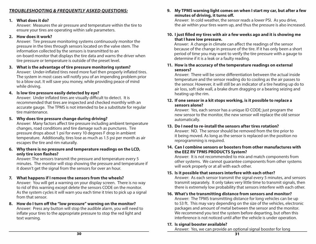
MonitorOPERATIONAL TEMPERATURE -4°F to 176°F
STORAGE TEMPERATURE -22°F to 185°F
CHARGER INPUT VOLTAGE DC 8 to 30V
TRANSMISSION FREQUENCY 433.92 MHz
SIZE 116 (L) x 68 (W) x 25 (H) mm
WEIGHT 4.87 ounces
Sensors - StandardOPERATIONAL TEMPERATURE -40°F to 176°F
STORAGE TEMPERATURE -40°F to 185°F
PRESSURE RANGE 0 to 13 bar, 0 to 188 psi
PRESSURE ACCURACY + +1.5 PSI (+0. BAR)
TEMPERATURE ACCURACY + +5 °F
TRANMISSION POWER <10dBm
TRANMISSION FREQUENCY 433.92 MHz
BATTERY LIFE 3-4 Years (CR1632 -40°F to 176°F)
SIZE diameter 22.6 mm height 22.6 mm (without antitheft housing) diameter 28 mm height 24 mm (with antitheft housing)
WEIGHT .5 ounces (without antitheft housing) .63 ounces (with antitheft housing)
Sensors - Flow ThroughOPERATIONAL TEMPERATURE -40°F to 176°F
STORAGE TEMPERATURE -40°F to 185°F
CHARGER INPUT VOLTAGE DC8 to 30V
TRANSMISSION FREQUENCY 433.92 MHz
SIZE 116 (L) x 68 (W) x 25 (H) mm
WEIGHT .78 ounces
Repeater/Signal Booster (optional parts)OPERATIONAL TEMPERATURE -4°F to 176°F
STORAGE TEMPERATURE -22°F to 185°F
WORKING VOLTAGE 12 to 24V
TRANMISSION POWER <18dBm
TRANMISSION FREQUENCY 433.92 MHz
SIZE 91 (L) x 38 (W) x 15 (H) mm
WEIGHT 1.48 ounces
30 31
TROUBLESHOOTING & FREQUENTLY ASKED QUESTIONS:
1. What does it do? Answer: Measures the air pressure and temperature within the tire to ensure your tires are operating within safe parameters.2. How does it work? Answer: Tire pressure monitoring systems continuously monitor the pressure in the tires through sensors located on the valve stem. The information collected by the sensors is transmitted to an on-board monitor that displays the tire data and warns the driver when tire pressure or temperature is outside of the preset level. 3. What is the advantage of tire pressure monitoring system? Answer: Under-inflated tires need more fuel then properly inflated tires. The system in most cases will notify you of an impending problem prior to a blow out. It will save you money, while providing peace of mind while driving. 4. Is low tire pressure easily detected by eye? Answer: Under inflated tires are visually difficult to detect. It is recommended that tires are inspected and checked monthly with an accurate gauge. The TPMS is not intended to be a substitute for regular tire maintenance. 5. Why does tire pressure change during driving? Answer: Many factors affect tire pressure including ambient temperature changes, road conditions and tire damage such as punctures. Tire pressure drops about 1 psi for every 10 degrees F drop in ambient temperature. Additionally, tires lose as much as 1.5 psi per month as air escapes the tire and rim naturally.6. Why there is no pressure and temperature readings on the LCD, only tire icon flashes? Answer: The sensors transmit the pressure and temperature every 5 minutes. The monitor will stop showing the pressure and temperature if it doesn’t get the signal from the sensors for over an hour. 7. What happens if I remove the sensors from the wheels? Answer: You will get a warning on your display screen. There is no way to rid of this warning except delete the sensors CODE on the monitor. As the system cycles it will warn you each time it tries to pick up a signal from that sensor.8. How do I turn off the “low pressure” warning on the monitor? Answer: Press any button will stop the audible alarm, you will need to inflate your tires to the appropriate pressure to stop the red light and text warning.
9. My TPMS warning light comes on when I start my car, but after a few minutes of driving, it turns off. Answer: In cold weather, the sensor reads a lower PSI. As you drive, the air within your tires warm up, and thus the pressure is also increased.
10. I just filled my tires with air a few weeks ago and it is showing me that I have low pressure. Answer: A change in climate can affect the readings of the sensor because of the change in pressure of the tire. If it has only been a short period of time you may want to verify the tire pressure with a gauge to determine if it is a leak or a faulty reading.11. How is the accuracy of the temperature readings on external sensors? Answer: There will be some differentiation between the actual inside temperature and the sensor reading do to cooling as the air passes to the sensor. However, it will still be an indicator of a tire heating up do to air loss, soft side wall, a brake drum dragging or a bearing seizing and heating up the rim.12. If one sensor in a kit stops working, is it possible to replace a sensors alone? Answer: Yes, each sensor has a unique ID CODE; just program the new sensor to the monitor, the new sensor will replace the old sensor automatically.13. Do I need to re-install the sensors after tires rotation? Answer: NO. The sensor should be removed from the tire prior to it being moved. As long as the sensor is replaced on the position no reprogramming is required.14. Can I combine sensors or boosters from other manufactures with the EEZ RV TPMS PRODUCTS System? Answer: It is not recommended to mix and match components from other systems. We cannot guarantee components from other systems will work properly or at all with each other. 15. Is it possible that sensors interfere with each other? Answer: As each sensor transmit the signal every 5 minutes, and sensors transmit separately. It only takes very little time to transmit signals, then there is extremely low probability that sensors interfere with each other.16. What’s the transmitting distance from sensors and monitor? Answer: The TPMS transmitting distance for long vehicles can be up to 53 ft. This may vary depending on the size of the vehicles, electronic packages and amount of metal between the sensor and the monitor. We recommend you test the system before departing, but often this interference is not noticed until after the vehicle is under operation. 17. Is signal booster available? Answer: Yes, we can provide an optional signal booster for long
32 33
vehicles if users want to make sure the monitor can read all sensors information. You may order an optional Repeater/Booster on our site at www.eezrvproducts.com.18. Can I reset the monitor to factory settings? Answer: Yes, to restore factory defaults, turn off the monitor, press the set button and turn on the monitor at the same time. The red light will flash and factory settings restored.19. Do I need a signal booster (transceiver)? Answer: The transmitting range for the EEZ RV PRODUCTS EezTire TPMS System sensors is around 53 ft., consideration should be taken for inner dual wheels, overhanging body work, metal tinted windows, the size of the tow vehicle, and the coaches electronics package, etc. which can block or impede the sensors signal strength. 20. Does this system measure temperature as well as pressure? Answer: Yes, unlike some systems from other suppliers that just measure pressure the EEZ RV PRODUCTS EezTire TPMS System measures internal tire air temperature and has an over temperature alarm. This can be an advantage on vehicles that are stored for long periods of time where brake calipers can stick after the first brake application and cause a dragging brake situation. As well as a back up to the low pressure alarm as increased internal tire temperature is caused by low or reduced air pressure.21. I am having CODE setting issues, what can cause those? Answer: Coding issues can be caused by incorrectly sized or bent valve actuators (Dill Valve) or valves torque to tight or to loose in the tire valve stem thus not allowing the sensor to operate. For issues coding sensors on a tire with valve extenders, the sensor should be tested on a tire valve with no extender to help isolate the problem. 22. I have an alarm, what should I do? Answer: First, pull over safely to the side of the road. Determine which wheel has an alarm, by checking the monitor icons; determine what type of alarm you have. It could be a leaking tire, a tire that has over pressure and too much air in it related to your base pressure setting, this can happen after a long run on a hot day, it could be an overheating situation etc. By checking the operating instructions you can see the different monitor icons that are associated with each condition, a flashing red light may or may not mean you have a deflation, each alarm icon tells you what the problem is. You will need to fix the problem before the red light will stop.23. What is the Sleep Mode? Answer: If the monitor is motionless for more than 15 minutes (vehicle stationary) it will shut down to save the battery. When it detects motion again it will beep and the screen will come to life signifying it has come out of sleep mode. If the monitor is shut off overnight, simply switch
the monitor back on prior to your departure and your real time tire pressure and temperatures will be updated in around 5 minutes on the monitor. Even if your monitor is in the sleep mode the system is always monitoring your tires and will alarm should any pressure or temperature become out of your set parameters.24. I am getting a Sensor Low Battery alarm, what should I do? Answer: Eventually all batteries lose power or die. The EEZ RV PRODUCTS sensor has replaceable batteries that can be easily replaced whenever needed. Please see above for detailed directions. The battery is a CR1632 watch type battery available from jewelry stores, electronics stores or on-line. On the road, a Walmart jewelry counter is the cheapest.25. How can I test the system? Answer: The system should be frequently tested for fast leak operation. The monitor should be placed in the driver’s location and sensors unscrewed then tightened one at a time. The fast leak alarm should operate and then reset on the monitor.26. Do I need a special tool to install the sensors? Answer: The EEZ RV PRODUCTS EezTire System comes with a complimentary Anti-Theft System on each sensor. In order to install a sensor you will have to use one of the 2 wrenches provided. You can easily remove the Anti-Theft housing by unscrewing the two halves of the Anti-Theft Housing; this will allow you to install the sensor by hand with no wrench. This can be beneficial when installing a sensor on your inside dual.27. Can I set different pressures for each tire or axle? Answer: Axles can be set to a different pressure, for tow & towed vehicles.28. Can I use tire valve extensions? Answer: Most tire valve extenders work ok, however if you have problems with sensors mounted on extenders, test the sensor on a regular valve stem location to see if it is a sensor problem or an extender problem. Alarms can sometimes be caused by loose extender connections.29. How accurate is the system? Answer: Our sensors are very accurate and any gauge readings should be made after resetting the sensors. Measurements of 1 psi need a controlled laboratory type system to be accurate. The tire pressure is accurate within +/- 1.5 PSI. Temperature is accurate to within +/- 5 degree F. The pressures and temperatures can vary dramatically from wheel to wheel depending on many factors, such as sun shining on one side, vehicle load, castor/ camber/alignment/brake temps. Even race cars turning left all the time generate higher pressures and temps on one side. Tire gauge accuracy can vary wildly and their quality is not dependent on their cost. Temperature compensation is a
34 35
requirement in a good gauge. (Gauges that read the same at -40 & 110 degrees) slide type gauges that rely on friction are often inaccurate. 30. How much air do I put in my tires? Answer: Always set the monitor pressure to the same as the cold inflation pressure. As an example some people set the monitor at 100 psi and then put 105 psi in the tire for good luck, by doing this the chance of over pressure alarms is increased.31. I get an alarm when I have been stopped for a while? Answer: In extreme cases it is possible to get a slow leak alarm after the vehicle has been pushed hard and the tire pressure has dramatically increased and upon stopping the tire cools quickly and the pressure drops simulating semi rapid air loss. This situation is often caused by high moisture content in the air in the tire. 32. How is my monitor powered? Answer: The monitor is powered by an internal rechargeable battery which holds a charge up to 60 hours before requiring recharging. A cigar lighter cord AND hard wire kit comes with the base system, this means you can take the monitor in your hand around your vehicle for sensor setup and tire pressure adjustment, it is like having an electronic tire gauge. 33. Does the system come with a warranty? Answer: Yes, it comes with a 3 year limited warranty on defective parts except batteries. Please see warranty section for full details.34. Do I have to enter special CODEs for each sensor on set-up? Answer: Each sensor comes pre programmed with its own unique CODE, for sensor set up the monitor detects each sensors CODE when they are installed.35. Is there anything special I need to do for winter storage? Answer: It’s a good idea to remove the sensors and monitor from your vehicle if parked for an extended time, especially in cold weather. Store the system in a warm location. Mark each sensors wheel position or store them in an egg carton so they can be replaced in the same wheel position to avoid having to do a new set up. Sensors use minimal power when they have no pressure on them.
CAUTIONS 1. The monitor should be installed inside the vehicle where it does not affect normal driving. 2. The monitor should be well fixed to avoid falling off during driving. 3. After the sensor installation, it is highly recommended to check for any air leakage. 4. Regular tire inspection and maintenance is still necessary. 5. After the system is installed correctly, the driver does not need to stare at the monitor all the time while driving. Alerts will be issued when abnormal conditions are found in the tires.
*Information in this manual is subject to change without notice.
LIMITED WARRANTY & GUARANTEEPlease contact the dealer you purchased it from to handle your warranty or guarantee issues. EEZ RV PRODUCTS will, within 36 months from date of original purchase, repair or replace free of charge any defective component (except batteries) which upon careful inspection is found, in our sole judgment, to have material or manufacturing defects, provided it is received freight prepaid, accompanied by the original purchasers sales slip and an authorized Return Merchandise Authorization number (RMA #.). If you purchased your unit directly from EEZ RV PRODUCTS you may obtain an RMA # by emailing [email protected].
DISCLAIMER OF WARRANTY: The warranty applies to the original purchaser only. The warranty does not carry over nor is it transferable to another party. Neither the seller nor the manufacturer will be liable for any loss damage or injury directly or indirectly arising from the use or inability to determine the use of this product. Before using, the user shall determine the suitability of the product for its intended use, and the user shall assume all responsibility and risk in connection herewith.
EEZ RV PRODUCTS, LLC • PO Box 414 • Quartzsite, AZ 85346 United States
www.eezrvproducts.com
© Copyright EEZ RV PRODUCTSAll Rights Reserved
36
Tire Pressure (cold)
Tire Pressure (cold)
Tire Pressure (cold)
Tire Pressure (cold)
High Parameter Setting
Low Parameter Setting
High Parameter Setting
Low Parameter Setting
High Parameter Setting
Low Parameter Setting
High Parameter Setting
Low Parameter Setting