eeRotorF4 Flight ontroller Manual 170422 - Rctimer...
10
BeeRotorF4 Flight Controller Manual 170422
Transcript of eeRotorF4 Flight ontroller Manual 170422 - Rctimer...

BeeRotorF4 Flight Controller
Manual 170422

2 / 10
Specification
• Power input: 5.0~5.5V
• Dimension: 36x36x9mm
• Fixing holes spacing: 30mm
• Weight: 8g
3 / 10
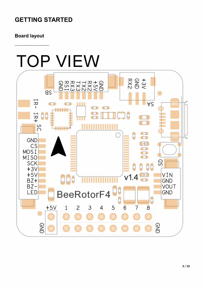
GETTING STARTED
Board layout
__________________
4 / 10
5 / 10
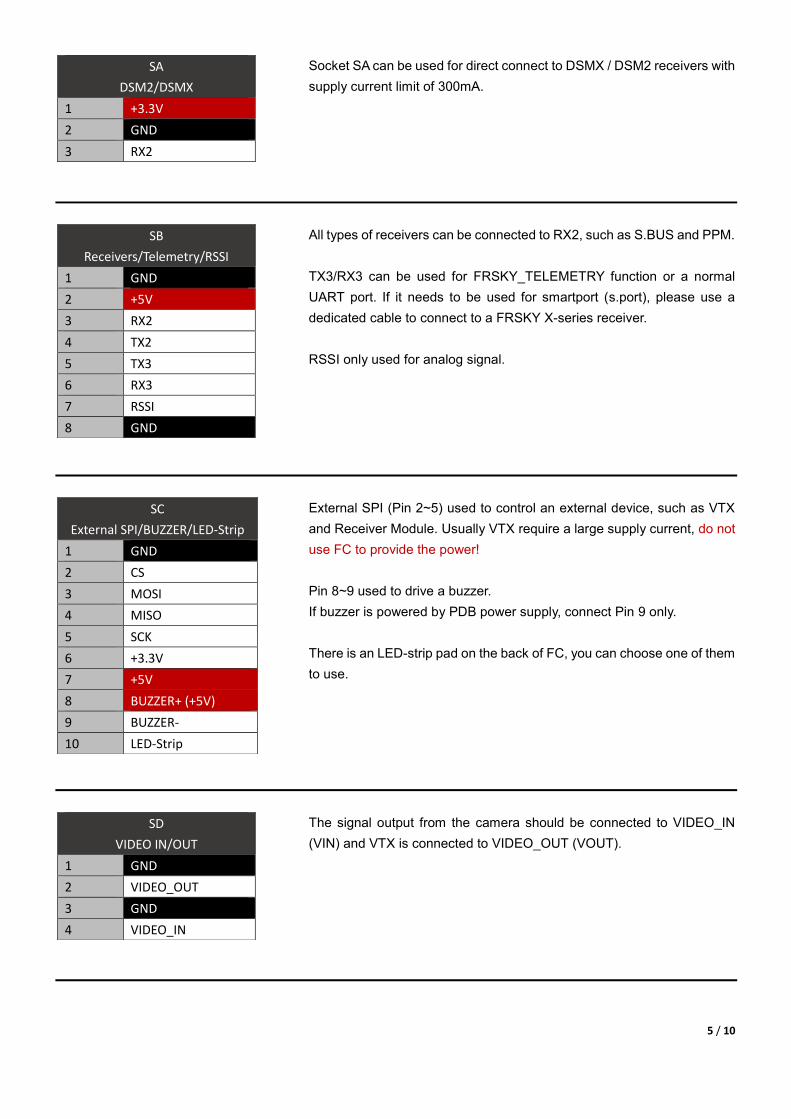
Socket SA can be used for direct connect to DSMX / DSM2 receivers with
supply current limit of 300mA.
All types of receivers can be connected to RX2, such as S.BUS and PPM.
TX3/RX3 can be used for FRSKY_TELEMETRY function or a normal
UART port. If it needs to be used for smartport (s.port), please use a
dedicated cable to connect to a FRSKY X-series receiver.
RSSI only used for analog signal.
External SPI (Pin 2~5) used to control an external device, such as VTX
and Receiver Module. Usually VTX require a large supply current, do not
use FC to provide the power!
Pin 8~9 used to drive a buzzer.
If buzzer is powered by PDB power supply, connect Pin 9 only.
There is an LED-strip pad on the back of FC, you can choose one of them
to use.
The signal output from the camera should be connected to VIDEO_IN
(VIN) and VTX is connected to VIDEO_OUT (VOUT).
SA
DSM2/DSMX
1 +3.3V
2 GND
3 RX2
SB
Receivers/Telemetry/RSSI
1 GND
2 +5V
3 RX2
4 TX2
5 TX3
6 RX3
7 RSSI
8 GND
SC
External SPI/BUZZER/LED-Strip
1 GND
2 CS
3 MOSI
4 MISO
5 SCK
6 +3.3V
7 +5V
8 BUZZER+ (+5V)
9 BUZZER-
10 LED-Strip
SD
VIDEO IN/OUT
1 GND
2 VIDEO_OUT
3 GND
4 VIDEO_IN

6 / 10
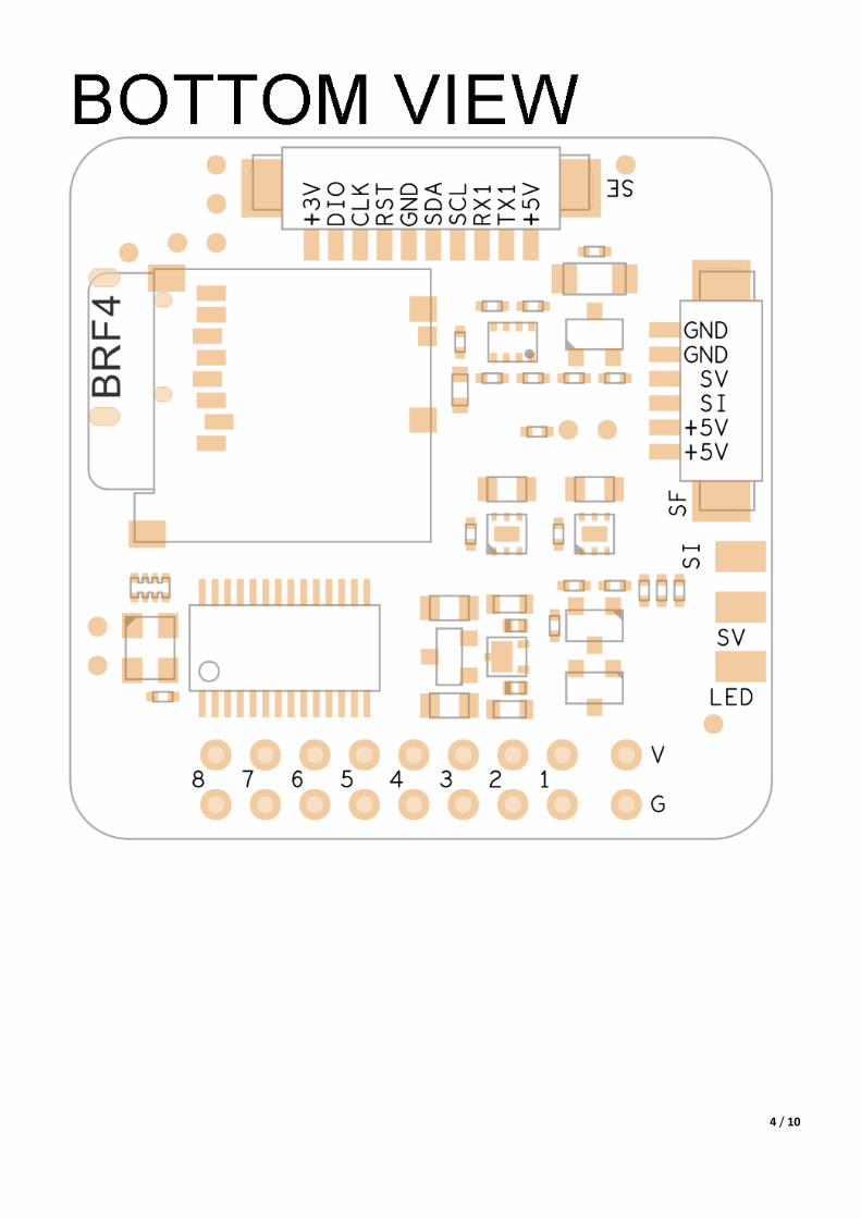
If you need to use GPS and compass, you can connect them to the SE.
WARNING!
Do not connect battery to the SF socket directly, it is only used for
Beerotor PDB!
If you do not have Beerotor PDB and want to measure voltage, please
solder the positive cable of battery to the SV pad on the back of FC.
If using a non-Beerotor PDB current signal, please solder it to the SI pad
on the back of FC.
SE
UART1/I2C/SWD
1 +5V
2 TX1
3 RX1
4 SCL
5 SDA
6 GND
7 RST
8 CLK
9 DIO
10 +3.3V
SF
PDB only
1 PWR_5V
2 PWR_5V
3 SENSE_I
4 SENSE_V
5 GND
6 GND
7 / 10
Basic Software Setup
__________________________
DFU Mode
BRF4 has two work modes after powered, normal mode and DFU mode. Hold the boot button while plugging in the
USB cable, and then release button, BRF4 will enter DFU mode. Otherwise, it is in the normal mode.
Install Virtual Comport (VCP) Driver
If the VCP driver of BRF4 unable installed automatically, please manually download the driver through the BetaFlight
configurator.
Install DFU Driver
BRF4 connect to computer via OTG function, you must install the appropriate drivers to ensure proper flash
firmware.
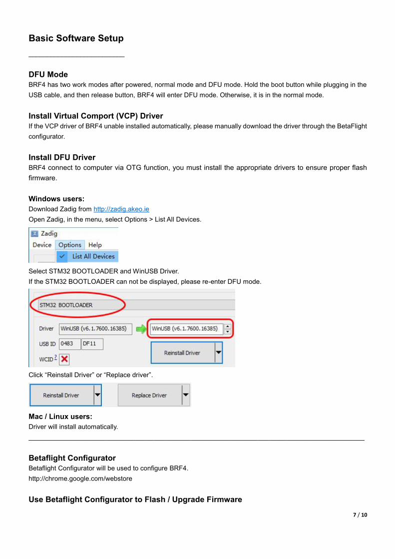
Windows users:
Download Zadig from http://zadig.akeo.ie
Open Zadig, in the menu, select Options > List All Devices.
Select STM32 BOOTLOADER and WinUSB Driver.
If the STM32 BOOTLOADER can not be displayed, please re-enter DFU mode.
Click “Reinstall Driver” or “Replace driver”.
Mac / Linux users:
Driver will install automatically.
___________________________________________________________________________________________
Betaflight Configurator
Betaflight Configurator will be used to configure BRF4.
http://chrome.google.com/webstore
Use Betaflight Configurator to Flash / Upgrade Firmware
8 / 10
Connect the BRF4 to your computer.
Open Betaflight Configurator, click the Firmware Flasher tab.
Select BEEROTORF4 and version in the Board menu.
Select Full chip erase.
Click Load Firmware [Online] and wait for the download is completed.
Click Flash Firmware and wait for the flash process is completed
___________________________________________________________________________________________
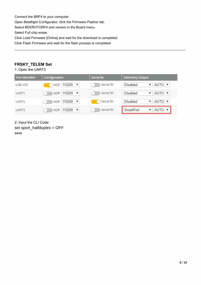
FRSKY_TELEM Set
1: Open the UART3
2: Input the CLI Code:
set sport_halfduplex = OFF
save

9 / 10

10 / 10