e/eM Style Standalone Keypad Installation/ Programming Manual · e/eM Style Standalone Keypad...
28
e/eM Style Standalone Keypad Installation/ Programming Manual This manual applies to these models: 212e, 212eM, 242e, and 242eM. This equipment is designed to be installed and serviced by security and lock industry professionals. Contents Section 1: Features and Product Description Section 2: Specifications Section 3: U.L. Requirements Section 4: Mounting Section 5: Wiring Section 6: Testing the Keypad Section 7: Programming Section 8: Troubleshooting Section 9: Programming Mode Loopback Section 10: Warranty Manual Revision Date: 12/10/04 Firmware Version: 1.0b Put Service Company Contact Information Here: Company Name: Service Number: Document # 6104401, Rev. 1.0, D1e 1
Transcript of e/eM Style Standalone Keypad Installation/ Programming Manual · e/eM Style Standalone Keypad...

e/eM Style StandaloneKeypad Installation/ProgrammingManual
This manual applies to these models: 212e, 212eM, 242e, and242eM.
This equipment is designed to be installed and serviced by securityand lock industry professionals.
ContentsSection 1: Features and Product DescriptionSection 2: SpecificationsSection 3: U.L. RequirementsSection 4: MountingSection 5: WiringSection 6: Testing the KeypadSection 7: ProgrammingSection 8: TroubleshootingSection 9: Programming Mode LoopbackSection 10: Warranty
Manual Revision Date: 12/10/04 Firmware Version: 1.0b
Put Service Company Contact Information Here:
Company Name:
Service Number:
Document # 6104401, Rev. 1.0, D1e 1

1. Features and ProductDescription1.1 Features
• Flush Mount• Indoor and Outdoor Use• Keypad Programmable• Access Control Functionality*• Individually Control up to 4 Devices*• Illuminated Backlit Keys (e keypad only)• Durable Metal Braille Keys (eM keypad only)• Keypress Feedback via Built-In Sounder• Bi-Color Red/Green LED Indicates Relay Status• Yellow LED Indicates Program Mode• 120 Users• Panic and Duress Options• Single Use Codes• Lockout Users• Two-Man Rule Option• 10 to 30 Volt DC Operation• 12 to 24 Volt AC Operation• 2 Amp Main Relay• Remote Trigger Input (REX)
*242 only
1.1.1 Access Control Function (242 factory settings)• Request to Exit Input• Door Monitoring Input• Relay Outputs
- Lock Release- Forced Door- Propped Door- Alarm Shunt
• Keypad Programmable
e/eM Style Standalone Installation/Programming Manual
2 Document # 6104401, Rev. 1.0, D1e
1.1.2 Output Functionality Options (242 field programma-ble settings)
• Request To Exit and Door Monitor Inputs• Four Independently Programmable Outputs• All Outputs Assignable by Code• Outputs Programmable For Latched or Timed Operation• Keypad Programmable
1.2 Product Description and Naming Convention
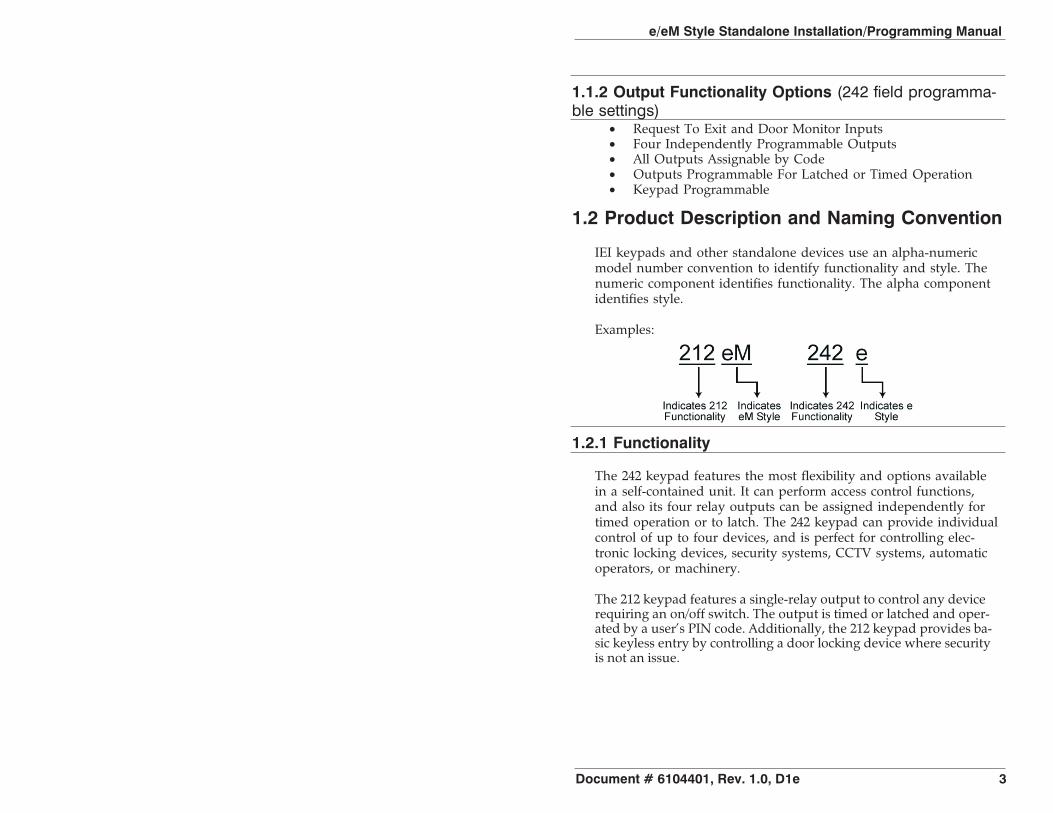
IEI keypads and other standalone devices use an alpha-numericmodel number convention to identify functionality and style. Thenumeric component identifies functionality. The alpha componentidentifies style.
Examples:
1.2.1 Functionality
The 242 keypad features the most flexibility and options availablein a self-contained unit. It can perform access control functions,and also its four relay outputs can be assigned independently fortimed operation or to latch. The 242 keypad can provide individualcontrol of up to four devices, and is perfect for controlling elec-tronic locking devices, security systems, CCTV systems, automaticoperators, or machinery.
The 212 keypad features a single-relay output to control any devicerequiring an on/off switch. The output is timed or latched and oper-ated by a user’s PIN code. Additionally, the 212 keypad provides ba-sic keyless entry by controlling a door locking device where securityis not an issue.
e/eM Style Standalone Installation/Programming Manual
Document # 6104401, Rev. 1.0, D1e 3

1.2.2 Style
e keypads: Flush mount backlit keypad.
eM keypads: Flush mount durable metal keypad.
All keypads: Designed for both indoor and outdoor flush mountapplications. The electronics for each keypad are conformal coatedin the manufacturing process in order to provide this level of appli-cation flexibility. Installation is easy. All keypads mount to anystandard single-gang electrical box or directly to any wall.
NOTE: This manual covers both 212 and 242 models. All fea-tures referring to the additional relays and outputs areavailable only on the 242 model.
e/eM Style Standalone Installation/Programming Manual
4 Document # 6104401, Rev. 1.0, D1e

2. SpecificationsParameter Range/DescriptionVoltage 10-30 VDC, 12-24 VAC (Auto-Adjusting)
Current
e:75mA@10VDC,100mA@30VDC,125mA@12VAC, and200mA@24VACeM:46mA@10VDC; 49mA@12VAC;60mA@24VAC; 68mA@30VDCAdd 20 mA for each energized aux relay
Environment Indoor and OutdoorTemperature Tolerance -20 °F to 130 °F (-28 °C to 54 °C)Dimensions 4.5" H x 2.75" W x 0.60" DMain Relay (Form C) Contact Rating: 2A @ 30VAC/DCAux Relay (Form C) Contact Rating: 1A @ 24V AC/DCREX Input Normally Open Dry ContactDoor Position Input Normally Closed Dry ContactLEDs Bi-Color Red/Green Yellow
Default SettingsParameter Default SettingMaster Code 1234Lock Output Relay 1 (Main Relay) (212 and 242)Alarm Shunt Relay 2 (242)Propped Door Relay 3 (242)Forced Door Relay 4 (242)Audio Alerts Not Assigned (212 and 242)REX Triggers Lock Output
REX Operation Always Triggers (regardless ofDoor Loop)
Error Lockout EnabledError Lockout Threshold 3 AttemptsError Lockout Duration 10 SecondsLock Output Time 5 SecondsPropped Door Time 30 SecondsForced Door Time 10 SecondsVisual Keypress Feedback EnabledAudio Keypress Feedback EnabledAuto-Entry DisabledUser Lockout Enabled
e/eM Style Standalone Installation/Programming Manual
Document # 6104401, Rev. 1.0, D1e 5

3. U.L. Requirements
NOTE: This section applies to the 212e and 242e keypads only.The 212eM and 242eM keypads are not U.L. Listed.
The 212e/242e keypad is a U.L. Listed access control unit. This sec-tion contains information regarding all the requirements necessaryto meet U.L. requirements.
This system must be installed in accordance with the National Elec-trical code (NFPA70), local codes, and the authorities having juris-diction. In addition, all wires and cables used must be strandedand shielded U.L. Listed and/or recognized wire.
All interconnecting devices (that is, door contacts, REX, locking de-vices, etc.) must be U.L. Listed. A U.L. Listed access control powerlimited power supply must be used to power the keypad.
A minimum of three user codes must be programmed into the key-pad for controlling access.
3.1 Tamper Requirements
To meet U.L. requirements, a U.L. Listed tamper switch must be in-stalled in the single gang box used for mounting the keypad. Thetamper switch must activate if the keypad is removed from the boxand must disconnect power from the lock. The lock must be a fail-secure device, meaning the lock remains locked when power is re-moved. In addition, once the tamper device is activated, it must beconfigured so that it can only be reset from within the protectedarea. Only a Sentrol 3012 or Sentrol 3025T tamper switch can beused. The diagrams on the next page show the suggested mount-ing location for each device.
e/eM Style Standalone Installation/Programming Manual
6 Document # 6104401, Rev. 1.0, D1e
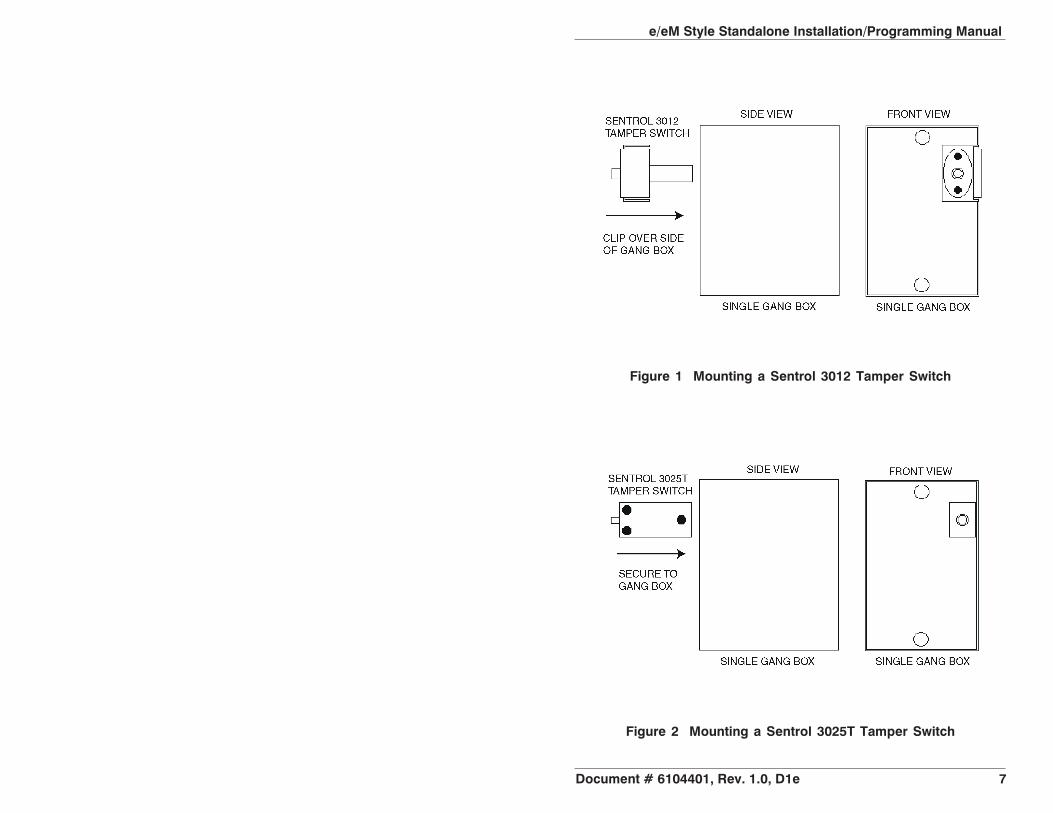
Figure 1 Mounting a Sentrol 3012 Tamper Switch
Figure 2 Mounting a Sentrol 3025T Tamper Switch
e/eM Style Standalone Installation/Programming Manual
Document # 6104401, Rev. 1.0, D1e 7

4. Mounting
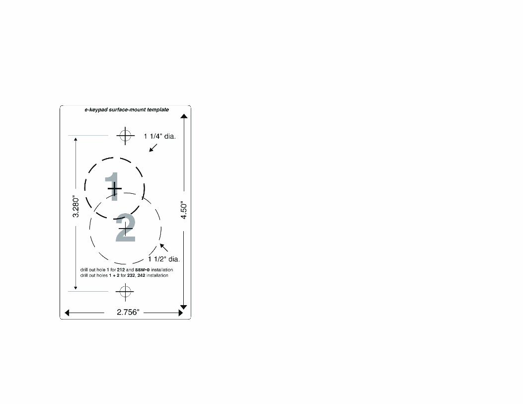
The keypad is designed to be flush mounted using a standard sin-gle-gang electrical box. In addition, it can be flush mounted di-rectly to the wall surface by cutting a hole in the wall. To properlysize the mounting and wire access hole, use the installation tem-plate on the last page in this manual and on the unit’s container.
Mounting height can vary depending on requirements. An appro-priate range is typically between 48 and 52 inches on center off thefloor.
For outdoor installations, use a weatherproof backbox and seal thewire entry locations with silicone and provide a drain hole. In addi-tion, use the anti-oxidant grease pack for the wire harness connec-tors.
Figure 3 Keypad Mounting Height
e/eM Style Standalone Installation/Programming Manual
8 Document # 6104401, Rev. 1.0, D1e
5. Wiring
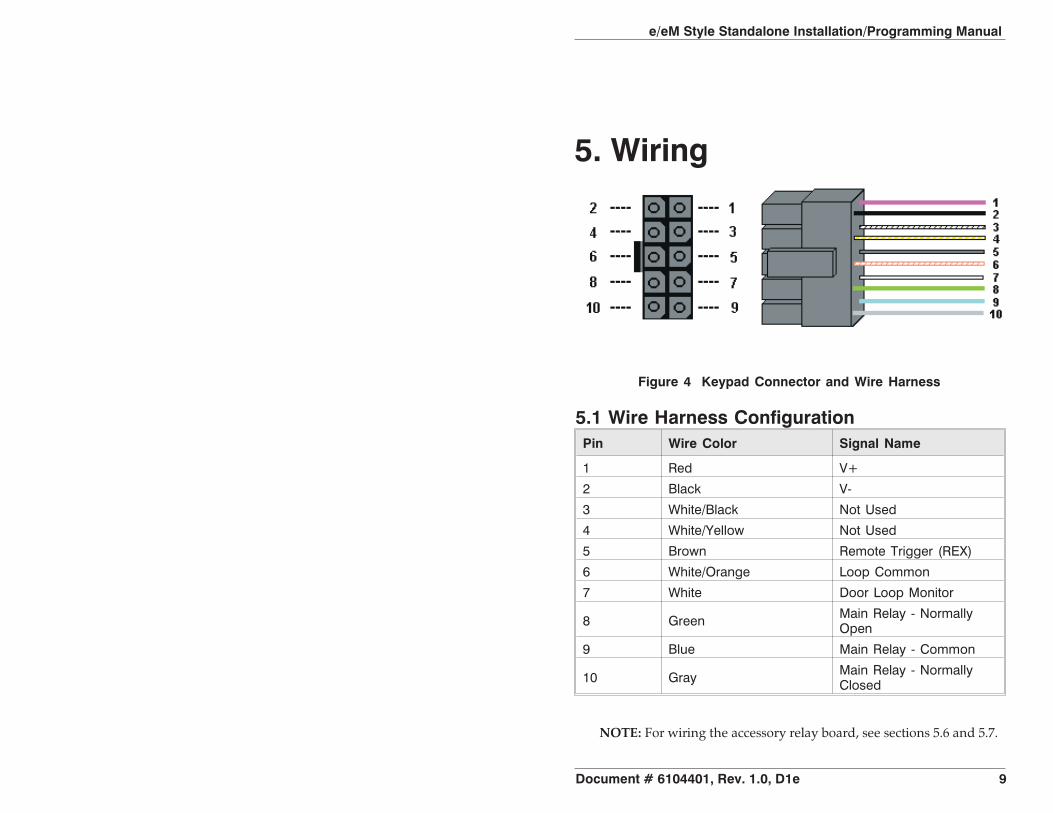
5.1 Wire Harness ConfigurationPin Wire Color Signal Name
1 Red V+
2 Black V-
3 White/Black Not Used
4 White/Yellow Not Used
5 Brown Remote Trigger (REX)
6 White/Orange Loop Common
7 White Door Loop Monitor
8 Green Main Relay - NormallyOpen
9 Blue Main Relay - Common
10 Gray Main Relay - NormallyClosed
Figure 4 Keypad Connector and Wire Harness
NOTE: For wiring the accessory relay board, see sections 5.6 and 5.7.
e/eM Style Standalone Installation/Programming Manual
Document # 6104401, Rev. 1.0, D1e 9

5.2 Wiring the Keypad to a Maglock (Fail-Safe)Use the following steps to connect the keypad to a Maglock (Fail-Safe):
1. Connect the red wire (V+) to the blue wire (common), andthen connect them to the positive on the power supply.
2. Connect the gray wire (normally closed) to the positive onthe maglock.
3. Connect the black wire (V-) to the negative on the Maglock,and then connect them to the negative on the power supply.
5.3 Wiring the Keypad to an Electric Strike(Fail-Secure)
Use the following steps to connect the keypad to an electric strike(fail-secure) (see Figure 6 for reference):
1. Connect the red wire (V+) to the blue wire (common), andthen connect them to the positive on the power supply.
2. Connect the green wire (normally open) to the positive onthe strike.
3. Connect the black wire (V-) to the negative on the strike, andthen connect them to the negative on the power supply.
Figure 5 Wiring the Keypad to a Maglock (Fail-Safe)
e/eM Style Standalone Installation/Programming Manual
10 Document # 6104401, Rev. 1.0, D1e
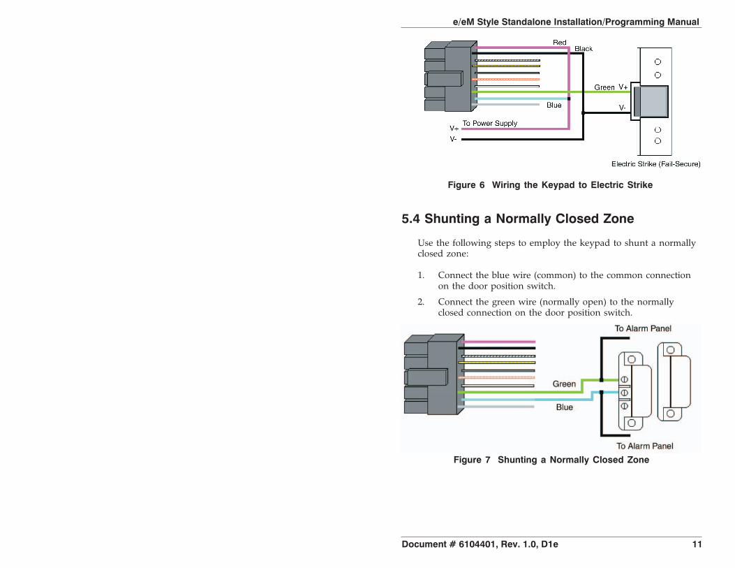
5.4 Shunting a Normally Closed Zone
Use the following steps to employ the keypad to shunt a normallyclosed zone:
1. Connect the blue wire (common) to the common connectionon the door position switch.
2. Connect the green wire (normally open) to the normallyclosed connection on the door position switch.
Figure 6 Wiring the Keypad to Electric Strike
Figure 7 Shunting a Normally Closed Zone
e/eM Style Standalone Installation/Programming Manual
Document # 6104401, Rev. 1.0, D1e 11
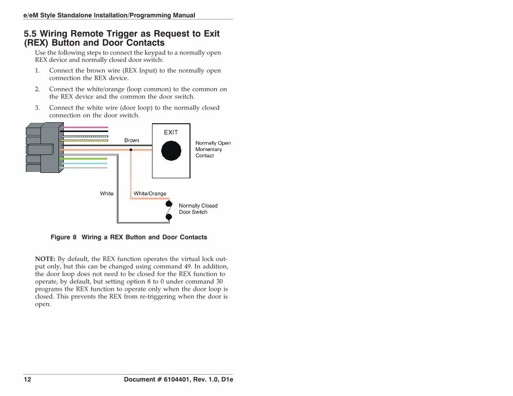
5.5 Wiring Remote Trigger as Request to Exit(REX) Button and Door Contacts
Use the following steps to connect the keypad to a normally openREX device and normally closed door switch:
1. Connect the brown wire (REX Input) to the normally openconnection the REX device.
2. Connect the white/orange (loop common) to the common onthe REX device and the common the door switch.
3. Connect the white wire (door loop) to the normally closedconnection on the door switch.
NOTE: By default, the REX function operates the virtual lock out-put only, but this can be changed using command 49. In addition,the door loop does not need to be closed for the REX function tooperate, by default, but setting option 8 to 0 under command 30programs the REX function to operate only when the door loop isclosed. This prevents the REX from re-triggering when the door isopen.
Figure 8 Wiring a REX Button and Door Contacts
e/eM Style Standalone Installation/Programming Manual
12 Document # 6104401, Rev. 1.0, D1e
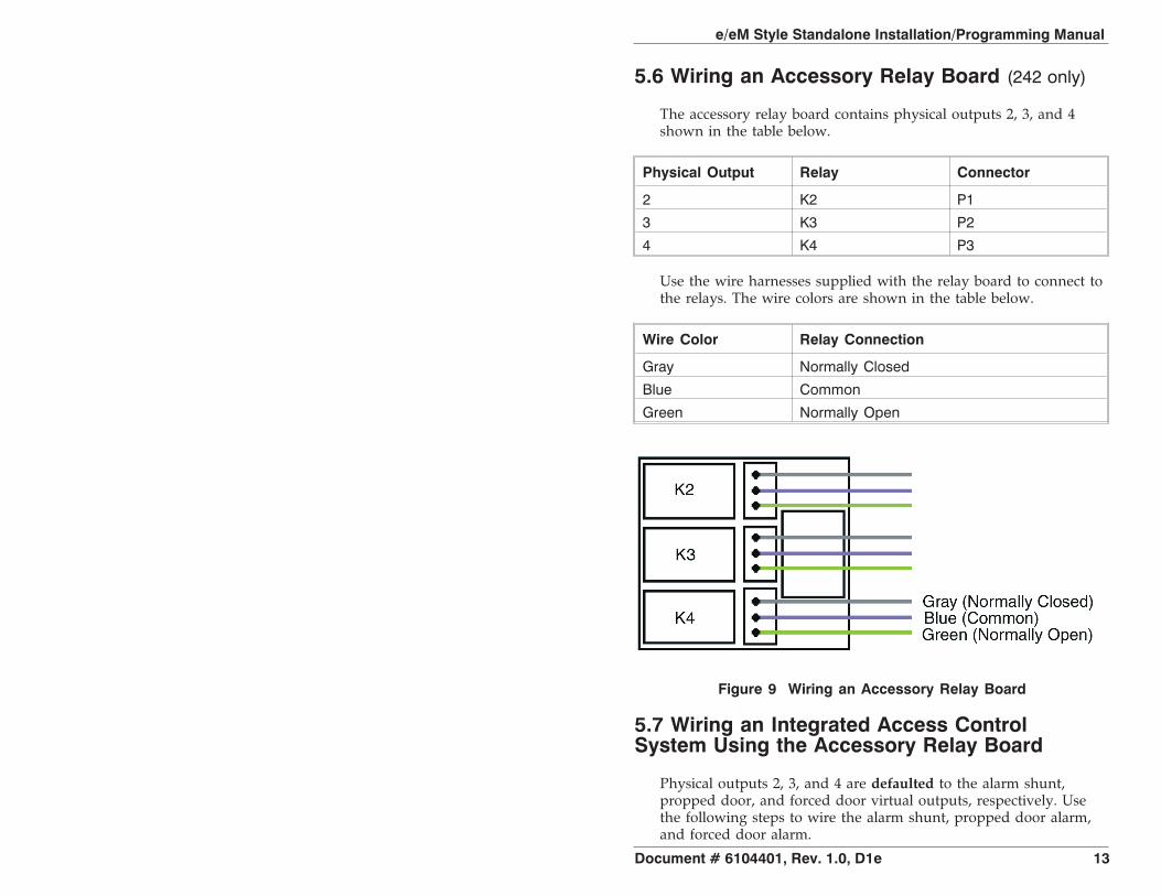
5.6 Wiring an Accessory Relay Board (242 only)
The accessory relay board contains physical outputs 2, 3, and 4shown in the table below.
Physical Output Relay Connector
2 K2 P1
3 K3 P2
4 K4 P3
Use the wire harnesses supplied with the relay board to connect tothe relays. The wire colors are shown in the table below.
Wire Color Relay Connection
Gray Normally Closed
Blue Common
Green Normally Open
5.7 Wiring an Integrated Access ControlSystem Using the Accessory Relay Board
Physical outputs 2, 3, and 4 are defaulted to the alarm shunt,propped door, and forced door virtual outputs, respectively. Usethe following steps to wire the alarm shunt, propped door alarm,and forced door alarm.
Figure 9 Wiring an Accessory Relay Board
e/eM Style Standalone Installation/Programming Manual
Document # 6104401, Rev. 1.0, D1e 13
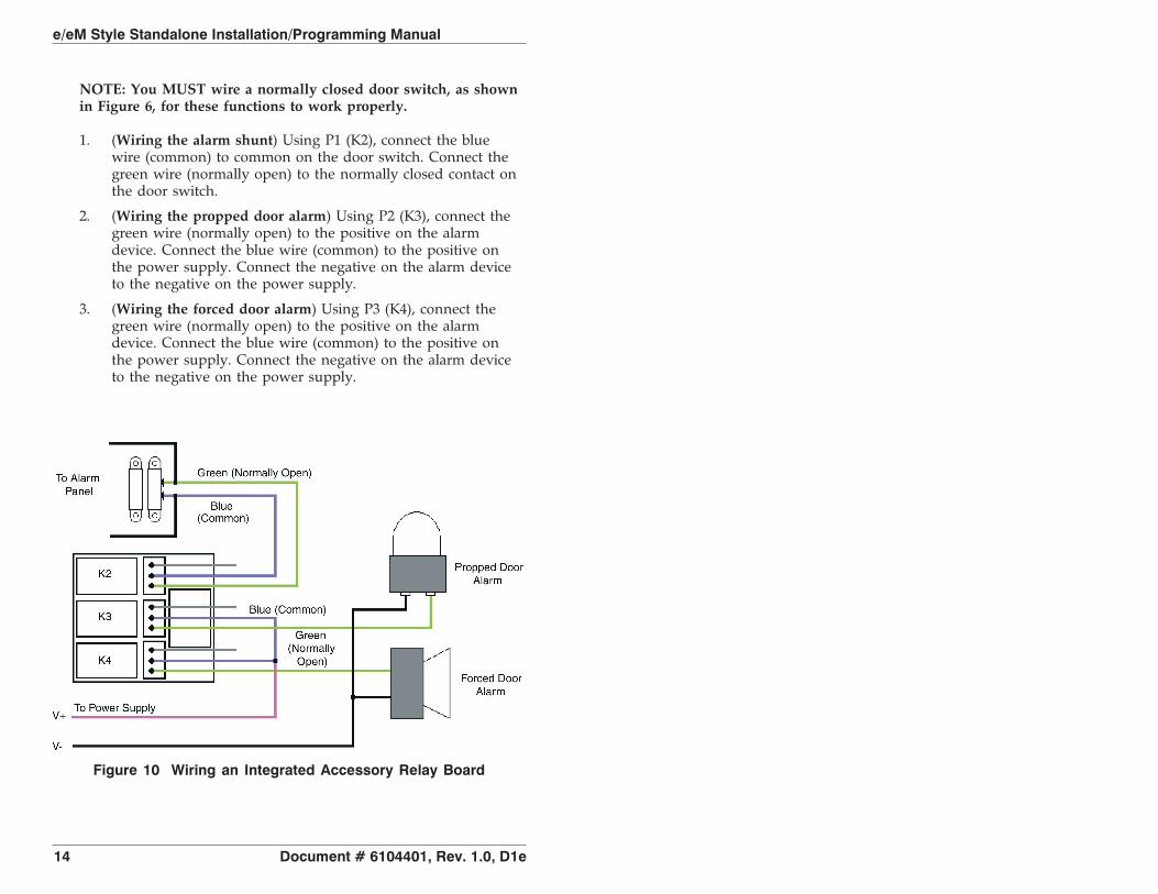
NOTE: You MUST wire a normally closed door switch, as shownin Figure 6, for these functions to work properly.
1. (Wiring the alarm shunt) Using P1 (K2), connect the bluewire (common) to common on the door switch. Connect thegreen wire (normally open) to the normally closed contact onthe door switch.
2. (Wiring the propped door alarm) Using P2 (K3), connect thegreen wire (normally open) to the positive on the alarmdevice. Connect the blue wire (common) to the positive onthe power supply. Connect the negative on the alarm deviceto the negative on the power supply.
3. (Wiring the forced door alarm) Using P3 (K4), connect thegreen wire (normally open) to the positive on the alarmdevice. Connect the blue wire (common) to the positive onthe power supply. Connect the negative on the alarm deviceto the negative on the power supply.
Figure 10 Wiring an Integrated Accessory Relay Board
e/eM Style Standalone Installation/Programming Manual
14 Document # 6104401, Rev. 1.0, D1e
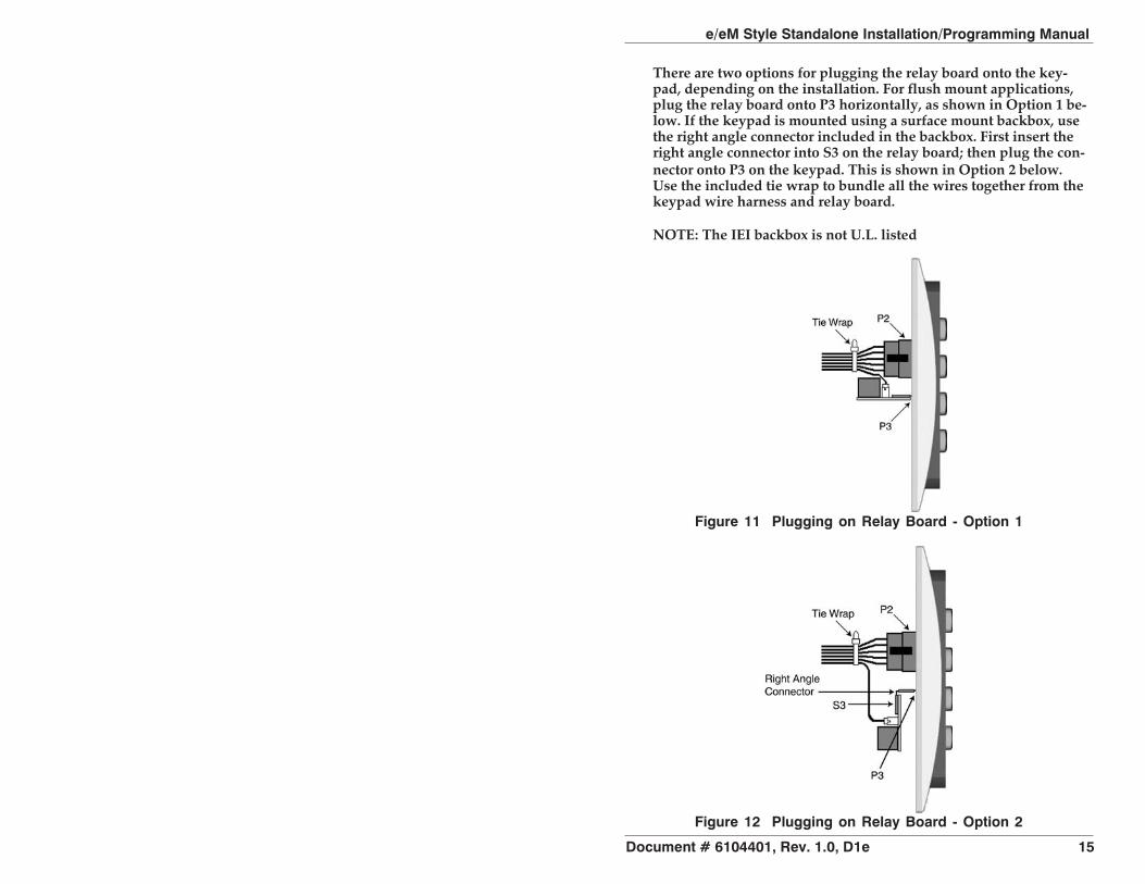
Figure 11 Plugging on Relay Board - Option 1
There are two options for plugging the relay board onto the key-pad, depending on the installation. For flush mount applications,plug the relay board onto P3 horizontally, as shown in Option 1 be-low. If the keypad is mounted using a surface mount backbox, usethe right angle connector included in the backbox. First insert theright angle connector into S3 on the relay board; then plug the con-nector onto P3 on the keypad. This is shown in Option 2 below.Use the included tie wrap to bundle all the wires together from thekeypad wire harness and relay board.
NOTE: The IEI backbox is not U.L. listed
Figure 12 Plugging on Relay Board - Option 2
e/eM Style Standalone Installation/Programming Manual
Document # 6104401, Rev. 1.0, D1e 15

6. Testing the Keypad
After installing the keypad, IEI recommends that you perform thekeypad self-test once a year, to ensure that the keypad works prop-erly.
1. To perform the self-test, with the unit powered up, press thefollowing keys on the keypad:
7890#123456*
• If all 12 keypresses are accepted, the keypad enters self-testmode.
• The LEDs alternate green, yellow, and red followed by thesounder beeping three times.
2. Verify that the master code works correctly. (The master codeaccesses program mode and activates the main relay to verifythat the locking device is working.)The default master code is 1234.
(If the default is not working, refer to section 9.)
e/eM Style Standalone Installation/Programming Manual
16 Document # 6104401, Rev. 1.0, D1e

7. Programming
To program the keypad, you must first enter program mode bypressing 99 # Master Code *. The default Master Code is 1234.
NOTE: If auto-entry is enabled, the * (asterisk) key is not used toenter Program mode. To change the Master Code, enter:
1 # new Master Code * new Master Code *
(To exit Program Mode, press *.)
7.1 Programming Order
To ensure that the keypad is programmed properly in the initialinstallation, program the keypad in the following order:
• Step 1: Assigning Virtual Outputs to Physical Outputs• Step 2: Programming Output Time Durations• Step 3: Programming Users• Step 4: Programming Keypad Options
7.2 Assigning Virtual Outputs to PhysicalOutputs
The keypad is equipped with eleven Virtual Outputs and six Physi-cal Outputs. Virtual Outputs are functions that you can assign to op-erate any Physical Output. Physical Outputs include the main relay,the three relays on the aux relay board, and the two audio alerts.
The 242 model has six physical outputs (four relays and two audioalerts). The 212 model has three physical outputs (a main relayand two audio alerts).
• Using command 10, you can assign any Virtual Output toany Physical Output or disable a Physical Output.
• Each Physical Output can only have one Virtual Outputassigned to it.
e/eM Style Standalone Installation/Programming Manual
Document # 6104401, Rev. 1.0, D1e 17

Command/Action Keys to Enter/Details
Command 10.Assign VirtualOutputs to PhysicalOutputs
10 # virtual output # physical output # **
Virtual Output List Physical Output List0 - No mapping 1 - Relay 1 (Main Relay)(physical output unused)1 - Lock 2 - Relay 2 (K2)2 - Alarm Shunt 3 - Relay 3 (K3)3 - Propped Door 4 - Relay 4 (K4)4 - Forced Door 9 - Audio Alert #15 - OUT2 10 - Audio Alert #26 - OUT37 - OUT48 - OUT513 - Duress14 - Panic15 - Keypad Active
* Audio alerts are described in section 7.2.2.
Defaults—Thekeypad comesprogrammed withthe following defaultoutput assignments:
The Lock Output is assigned to Relay 1, theAlarm Shunt Output to Relay 2, the ProppedDoor Output to Relay 3, and the ForcedDoor Output to Relay 4.
7.2.1 Virtual OutputsVirtual Output Description/Details
Lock This output is used for your locking device.
Alarm Shunt
This is used to shunt out an existing alarmpanel. It activates with the lock output andde-energizes one second after the lock timeexpires.
Propped Door
This output activates after entering a validuser code only if the door position switch isleft open longer than the programmedpropped door time.
e/eM Style Standalone Installation/Programming Manual
18 Document # 6104401, Rev. 1.0, D1e

Virtual Output Description/Details
Forced DoorThis output activates if the door positionswitch is opened without entering a validuser code.
OUT2, OUT3, OUT4,OUT5
These four independently controlled outputsare activated by user codes programmed toactivate multiple outputs and the REXfunction. See programming commands 59and 49 in the Programming section.
DuressThe duress output is activated when aduress user enters their code. See DuressUser in the Programming section.
Panic
Panic is activated by pressing the * and #keys at the same time. This is used in caseof emergency to activate an auxiliary deviceand should not be used to gain access.
Keypad ActiveThe Keypad Active output is activated whenany key is pressed. Do not use this outputto gain access.
7.2.2 Audio Alerts
Audio Alerts are produced by the local sounder on the keypadand can be used as a local propped door alarm or forced dooralarm to free up the other relays for other functions.
• Alert #1 is a constant quick beep (¼ second on and ¼ sec-ond off).
• Alert #2 is a short beep (100 ms) every two seconds.• Alert #1 takes priority over Alert #2.
7.2.3 Programming REX Outputs
For wiring information, see section 5.5.
49 # output list # 0 # **
(Use this command to program which outputs the REX operates.1 = LOCK, 2 = OUT2, 3 = OUT3,4 = OUT4, and 5 = OUT4.)
e/eM Style Standalone Installation/Programming Manual
Document # 6104401, Rev. 1.0, D1e 19

7.3 Programming Output Time DurationsCommand/Action Keys to Enter/Details
Command 11. SetLOCK Time Duration
11 # time # 0 # * * (time = 1 to 255seconds)
Command 12. SetOUT2 Time Duration 12 # ttt # pre # * *
Command 13. SetOUT3 Time Duration 13 # ttt # pre # * *
Command 14. SetOUT4 Time Duration 14 # ttt # pre # * *
Command 15. SetOUT5 Time Duration 15 # ttt # pre # **
Options:
ttt
(Example:)
number of time units to operate OUTn whenvalid PIN entered (1 through 255)12 # 1 # 10 # (for ten seconds)
pre
(Example:)
number of seconds in each time unit(prescaler)
12 # 15 # 1 # (for fifteen seconds)
Command 44. SetPropped Door Time 44 # time # 0 # * *
Options:
time
Propped Door Time - rounded down tonearest 10’s of seconds; entered as 00, 10through 990, defaults to 30 seconds;entering a time of zero disables the proppeddoor function
Command 45. SetForced Door Time 45 # time # 0 # * *
Options:
time
Forced Door Time - rounded down tonearest 10’s of seconds; entered as 00, 10through 990, defaults to 10 seconds;entering a time of zero latches the virtualforced door that can be cleared with anyvalid PIN or by entering program mode
e/eM Style Standalone Installation/Programming Manual
20 Document # 6104401, Rev. 1.0, D1e
Command/Action Keys to Enter/Details
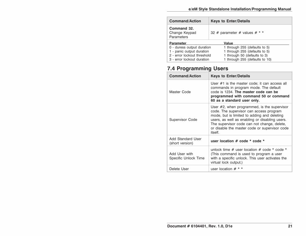
Command 32.Change KeypadParameters
32 # parameter # values # * *
Parameter Value0 - duress output duration 1 through 255 (defaults to 5)1 - panic output duration 1 through 255 (defaults to 5)2 - error lockout threshold 1 through 50 (defaults to 3)3 - error lockout duration 1 through 255 (defaults to 10)
7.4 Programming UsersCommand/Action Keys to Enter/Details
Master Code
User #1 is the master code; it can access allcommands in program mode. The defaultcode is 1234. The master code can beprogrammed with command 50 or command60 as a standard user only.
Supervisor Code
User #2, when programmed, is the supervisorcode. The supervisor can access programmode, but is limited to adding and deletingusers, as well as enabling or disabling users.The supervisor code can not change, delete,or disable the master code or supervisor codeitself.
Add Standard User(short version) user location # code * code *
Add User withSpecific Unlock Time
unlock time # user location # code * code *(This command is used to program a userwith a specific unlock. This user activates thevirtual lock output.)
Delete User user location # * *
e/eM Style Standalone Installation/Programming Manual
Document # 6104401, Rev. 1.0, D1e 21
Command/Action Keys to Enter/Details
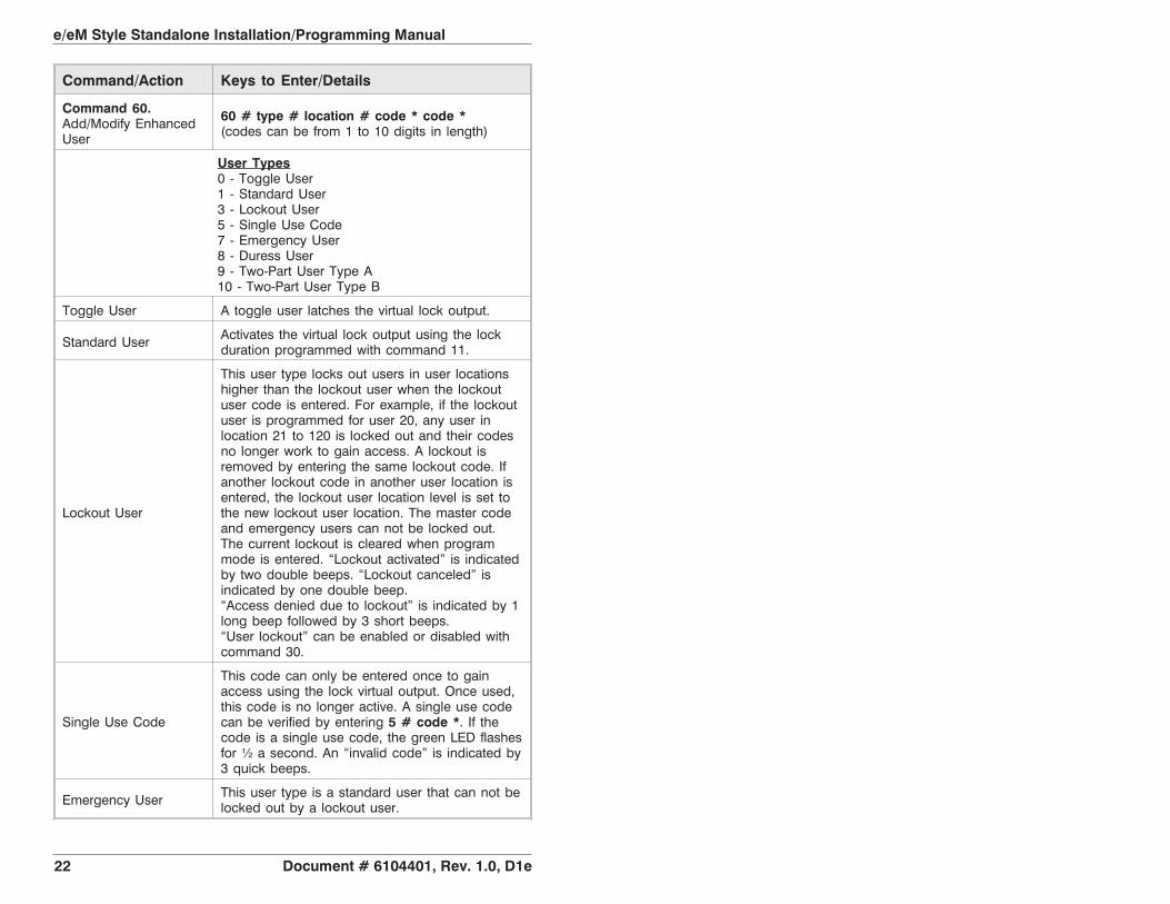
Command 60.Add/Modify EnhancedUser
60 # type # location # code * code *(codes can be from 1 to 10 digits in length)
User Types0 - Toggle User1 - Standard User3 - Lockout User5 - Single Use Code7 - Emergency User8 - Duress User9 - Two-Part User Type A10 - Two-Part User Type B
Toggle User A toggle user latches the virtual lock output.
Standard User Activates the virtual lock output using the lockduration programmed with command 11.
Lockout User
This user type locks out users in user locationshigher than the lockout user when the lockoutuser code is entered. For example, if the lockoutuser is programmed for user 20, any user inlocation 21 to 120 is locked out and their codesno longer work to gain access. A lockout isremoved by entering the same lockout code. Ifanother lockout code in another user location isentered, the lockout user location level is set tothe new lockout user location. The master codeand emergency users can not be locked out.The current lockout is cleared when programmode is entered. “Lockout activated” is indicatedby two double beeps. “Lockout canceled” isindicated by one double beep.“Access denied due to lockout” is indicated by 1long beep followed by 3 short beeps.“User lockout” can be enabled or disabled withcommand 30.
Single Use Code
This code can only be entered once to gainaccess using the lock virtual output. Once used,this code is no longer active. A single use codecan be verified by entering 5 # code *. If thecode is a single use code, the green LED flashesfor ½ a second. An “invalid code” is indicated by3 quick beeps.
Emergency User This user type is a standard user that can not belocked out by a lockout user.
e/eM Style Standalone Installation/Programming Manual
22 Document # 6104401, Rev. 1.0, D1e

Command/Action Keys to Enter/Details
Duress User
Entering a duress code activates the lock andduress virtual outputs. This allows you to triggeranother device silently, such as an alarm, andstill gain access in case of an emergency.
Two-Part Users Aand B
When the two-part user option is enabled, twocodes are required to gain access. A “Two-PartType A” and “Two-Part Type B” user must entertheir code (not necessarily in that order). Afterthe first code is entered, the LED alternatesbetween red and green, indicating another codeis required. The second code must be enteredwithin 15 seconds of the first code. When twocodes of the same type are entered, a typemismatch is indicated by 5 beeps. WhenTwo-Part User is disabled, all Type A and B usercodes are converted to standard user codes.Two-Part users activate the virtual lock output.Two-Part Users can be enabled or disabled withcommand 30.
Command 56.Enable/Disable User 56 # enable/disable # user location # * *
Options: 1 = Disable0 = EnableThe master code and supervisor codecannot be disabled.
Command 59.Program users tooperate virtual outputsOUT2, OUT3, OUT4,and OUT5 as well asthe virtual lock output.
59 # output list # location # code * code *(Use this command to operate multiple outputsand the virtual lock output using a single code.This is useful when you want to operate aseparate device while unlocking the door andstill use some of the access control featuressuch as alarm shunt, propped door, forced doorand REX.
The output list is specified by entering theoutput(s) you want the code to operate.1 = LOCK, 2 = OUT2, 3 = OUT3,4 = OUT4, and 5 = OUT5.
e/eM Style Standalone Installation/Programming Manual
Document # 6104401, Rev. 1.0, D1e 23

7.5 Programming Keypad OptionsCommand/Action Keys to Enter/Details
Command 30.Enable/Disable keypadoptions
30 # option # enable/disable # * *
Option Set/Clear0 - audio keypress feedback 0=disabled, 1=ENABLED1 - visual keypress feedback 0=disabled, 1=ENABLED2 - auto-entry enable 0=DISABLED, 1=enabled3 - error lockout 0=disabled, 1=ENABLED4 - user lockout 0=disabled, 1=ENABLED5 - two-part users 0=disabled, 1=ENABLED6 - keypad illumination 0=disabled, 1=ENABLED7 - keypad dimming 0=disabled, 1=ENABLED8 - REX operation 0=only when door loop closed
1=alwaysDefaults are in bold. Options 6 and 7 available only in e keypads.
Auto-entry
When auto-entry is enabled, users with codesthe same length as the master code do not haveto press the * key after entering their code. Ifyou have a code greater than the master code,you can use Auto-Entry Suspend. Just enter the# key prior to your code followed by the * key.Example:# 23456 * if the master code is four digits.
Error Lockout
When enabled, the keypad keeps track of thenumber of consecutive invalid codes entered,including attempts to access program mode.When the threshold is reached, the yellow LEDturns on solid and the keypad no longerresponds to key presses for the programmedtime duration. The count is reset by entering avalid code, including entering program mode.The error lockout threshold and duration isprogrammed with command 32.
Keypad Illumination Keypad backlighting can be enabled or disabled.
Keypad Dimming
When enabled, the backlighting illumination leveldecreases 15 seconds after the last key press.When disabled, the backlighting remains at fullillumination at all times.
Command 40. Resetdefaults only.
40 # 00000 # 00000 # ** (master code, allkeypad options and parameters)
Command 46. EraseUsers and ResetDefault Settings.
46 # 00000 # 00000 # **
e/eM Style Standalone Installation/Programming Manual
24 Document # 6104401, Rev. 1.0, D1e

8. Troubleshooting
Refer to this section if the keypad is not operating correctly as de-scribed in this manual.
Problem Solution
The LEDs are slowlycycling from right toleft and backlighting isoff.
The keypad is designed to monitor the inputvoltage and this is an indication of under-voltage.The under-voltage threshold is set to 8.5VDC,and when the voltage drops below this limit, thelow voltage warning starts and backlighting isturned off. To solve, raise the voltage to between12-24V.
The LEDs are rapidlycycling from left toright and the keypadhas lost all operation.
The keypad is designed to monitor the inputvoltage, and this is an indication of over-voltage.The over- voltage threshold is set to 36VDC, andwhen the voltage rises above this limit, theover-voltage warning starts and the keypad losesall operation. To solve, lower the voltage tobetween 12-24V.
The master code doesnot work.
Perform the programming mode loopback andreset the master code using the programmingcommand.
No LEDs are lit on thekeypad
Power is not reaching the keypad. Using avoltmeter, confirm that there is voltage at thekeypad on the red and black wires. If there is novoltage at the keypad, verify that there is voltageat the power supply. If there is no voltage at thepower supply, call the manufacturer of the powersupply. If there is voltage at the power supplybut not at the keypad, verify there is no break inthe wires, then check continuity in the wholelength of the wire run. To verify that the keypadis working, you can power the keypad with a12-Volt Battery.
If the keypad still does not work after troubleshooting, please callIEI’s technical support department at 1-800-343-9502 (outside MA)or 1-800-733-9502 (inside MA). Operating hours are Mondaythrough Friday from 8:00 A.M. to 7:00 P.M. Eastern Standard Time.
e/eM Style Standalone Installation/Programming Manual
Document # 6104401, Rev. 1.0, D1e 25
9. Programming ModeLoopback
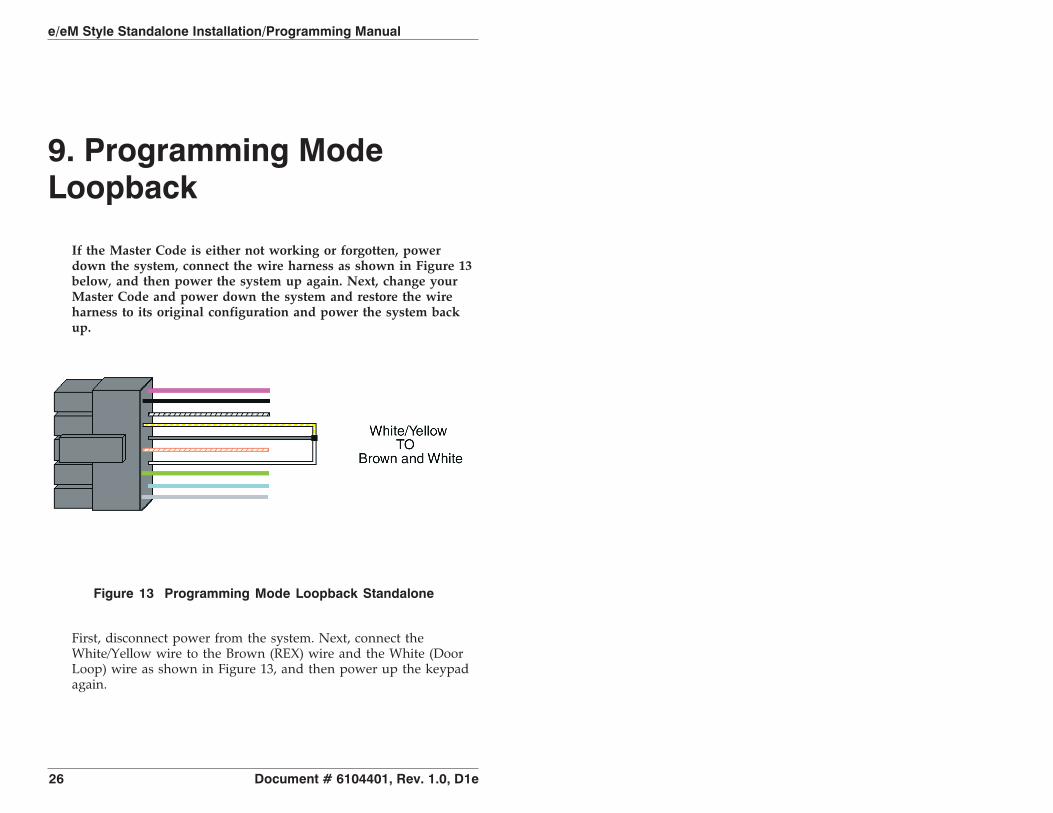
If the Master Code is either not working or forgotten, powerdown the system, connect the wire harness as shown in Figure 13below, and then power the system up again. Next, change yourMaster Code and power down the system and restore the wireharness to its original configuration and power the system backup.
First, disconnect power from the system. Next, connect theWhite/Yellow wire to the Brown (REX) wire and the White (DoorLoop) wire as shown in Figure 13, and then power up the keypadagain.
Figure 13 Programming Mode Loopback Standalone
e/eM Style Standalone Installation/Programming Manual
26 Document # 6104401, Rev. 1.0, D1e

10. Warranty
International Electronics Inc. (IEI) warrants its products to be freefrom defects in material and workmanship when they have beeninstalled in accordance with the manufacturer’s instructions andhave not been modified or tampered with. IEI does not assumeany responsibility for damage or injury to person or property dueto improper care, storage, handling, abuse, misuse, normal wearand tear, or an act of God.
IEI’s sole responsibility is limited to the repair (at IEI’s option) orthe replacement of the defective product or part when sent to IEI’sfacility (freight and insurance charges prepaid) after obtainingIEI’s Return Material Authorization. IEI will not be liable to thepurchaser or any one else for incidental or consequential damagesarising from any defect in, or malfunction of, its products.
Except as stated above, IEI makes no warranties, either expressedor implied, as to any matter whatsoever, including, and withoutlimitation to, the condition of its products, their merchantability, orfitness for any particular purpose.
Warranty Periods Are:
1 Year PowerKey
2 Years Door Gard & Secured SeriesProducts
2 Years LS Series
2 Years Glass Break
5 Years e and eM Style Keypads
All products have date code labeling to determine the warranty period. A90-day grace period is added to all products to account for shelf life.