eeEmbedded D8.1 SOA Platform...
72
This project has received funding from the European Union Seventh Framework Programme under grant agreement n° 609349. OPTIMISED DESIGN METHODOLOGIES FOR ENERGY-EFFICIENT BUILDINGS INTEGRATED IN THE NEIGHBOURHOOD ENERGY SYSTEMS eeEmbedded – D8.1 SOA Platform Architecture Responsible Authors: Amrita Sukumar (RIB), Arne Tøn (EPM), Klaus Linhard (IAB), Eduard Mrazek (NEM), Marc Mosch (TUD-CIB), Peter Katranuschkov (TUD-CIB) Co-Authors: Georg Dangl (IAB), Wolfgang Müller (RIB), Ken Baumgärtel (TUD-CIB), Mathias Kadolsky (TUD-CIB), Raimund Zellner (NEM) Due date: 30.06.2015 Issue date: 15.11.2015 Nature: Other Coordinator: R. J. Scherer, Institute for Construction Informatics, Technische Universität Dresden, Germany
Transcript of eeEmbedded D8.1 SOA Platform...

This project has received funding from the European Union Seventh Framework Programme
under grant agreement n° 609349.
OPTIMISED DESIGN METHODOLOGIES FOR ENERGY-EFFICIENT
BUILDINGS INTEGRATED IN THE NEIGHBOURHOOD ENERGY SYSTEMS
eeEmbedded – D8.1
SOA Platform Architecture
Responsible Authors:
Amrita Sukumar (RIB), Arne Tøn (EPM), Klaus Linhard (IAB),
Eduard Mrazek (NEM), Marc Mosch (TUD-CIB), Peter Katranuschkov (TUD-CIB)
Co-Authors:
Georg Dangl (IAB), Wolfgang Müller (RIB), Ken Baumgärtel (TUD-CIB),
Mathias Kadolsky (TUD-CIB), Raimund Zellner (NEM)
Due date: 30.06.2015
Issue date: 15.11.2015
Nature: Other
Coordinator: R. J. Scherer, Institute for Construction Informatics, Technische Universität Dresden, Germany
D8.1 SOA Platform Architecture
Page 2/72
© eeEmbedded Consortium www.eeEmbedded.eu
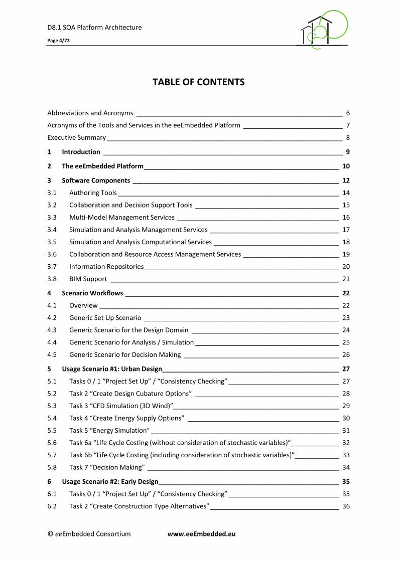
Start date of project: 01.10.2013 Duration: 48 months
Organisation name of lead contractor for this deliverable: RIB Software
History
Version Description Author Date
0.1 Initial Deliverable Structuring Amrita Sukumar (RIB) 30/01/2015
0.2 Extended Work Structure
Amrita Sukumar (RIB), Klaus Linhard (IAB), Georg Dangl (IAB),
Arne Tøn (EPM)
18/02/2015
0.3 Partner Contributions All Partners 29/04/2015
0.4 Discussion/ Restructuring/ Revised version with comments
Peter Katranuschkov (CIB), Marc Mosch (CIB)
14/05/2015
0.5 Refining the Data & Module Structure Peter Katranuschkov (CIB), Marc Mosch (CIB)
04/06/2015
0.6 Report structure and initial contributions to the document
Amrita Sukumar (RIB), Klaus Linhard (IAB), Georg Dangl (IAB)
22/07/2015
0.7 Fully reworked report structure aligned with all developments and findings
Peter Katranuschkov (CIB), Marc Mosch (CIB)
11/09/2015
0.8 Extended & Updated Partner Contributions
All Partners 20/10/2015
0.9 Consolidated pre-final version Arne Tøn (EPM), Peter Katranuschkov (CIB)
23/10/2015
0.91 Final partner contributions
All partners 30/10/2015
0.92 Final Revision Amrita Sukumar (RIB)
Marc Mosch (CIB) Peter Katranuschkov (CIB)
14/11/2015
1.0 Final Version
Amrita Sukumar (RIB) Peter Katranuschkov (CIB)
15/11/2015
Copyright
This report is © eeEmbedded Consortium 2015. Its duplication is restricted to the personal use within
the consortium, the funding agency and the project reviewers. Its duplication is allowed in its integral
form only for anyone's personal use for the purposes of research or education.
Citation
Sukumar, A., Tøn, A., Linhard, K., Mrazek, E., Mosch, M. & Katranuschkov P. (2015): eeEmbedded
Deliverable D8.1: SOA Platform Architecture, © eeEmbedded Consortium, Brussels.

D8.1 SOA Platform Architecture
Page 3/72
© eeEmbedded Consortium www.eeEmbedded.eu
Acknowledgements
The work presented in this document has been conducted in the context of the seventh framework
programme of the European community project eeEmbedded (n° 609349). eeEmbedded is a 48
month project that started in October 2013 and is funded by the European Commission as well as by
the industrial partners. Their support is gratefully appreciated. The partners in the project are
Technische Universität Dresden (Germany), Fraunhofer-Gesellschaft zur Förderung der angewandten
Forschung E.V (Germany), NEMETSCHEK Slovensko, S.R.O. (Slovakia), Data Design System ASA
(Norway), RIB Information Technologies AG (Germany), Jotne EPM Technology AS (Norway),
Granlund OY (Finland), SOFISTIK HELLAS AE (Greece), Institute for applied Building Informatics IABI
(Germany), FR. SAUTER AG (Switzerland), , Obermeyer Planen + Beraten (Germany), Centro de
Estudios Materiales y Control de Obras S.A. (Spain), STRABAG AG (Austria) and Koninklijke BAM
Group NV (The Netherlands). This report owes to a collaborative effort of the above organizations.
Project of SEVENTH FRAMEWORK PROGRAMME OF THE EUROPEAN COMMUNITY
Dissemination Level
PU Public X
PP Restricted to other programme participants (including the Commission Services)
RE Restricted to a group specified by the consortium (including the Commission Services)
CO Confidential, only for members of the consortium (including the Commission Services)
D8.1 SOA Platform Architecture
Page 4/72
© eeEmbedded Consortium www.eeEmbedded.eu
TABLE OF CONTENTS
Abbreviations and Acronyms ________________________________________________________ 6
Acronyms of the Tools and Services in the eeEmbedded Platform ___________________________ 7
Executive Summary ________________________________________________________________ 8
1 Introduction _________________________________________________________________ 9
2 The eeEmbedded Platform _____________________________________________________ 10
3 Software Components ________________________________________________________ 12
3.1 Authoring Tools ____________________________________________________________ 14
3.2 Collaboration and Decision Support Tools _______________________________________ 15
3.3 Multi-Model Management Services ____________________________________________ 16
3.4 Simulation and Analysis Management Services ___________________________________ 17
3.5 Simulation and Analysis Computational Services __________________________________ 18
3.6 Collaboration and Resource Access Management Services __________________________ 19
3.7 Information Repositories_____________________________________________________ 20
3.8 BIM Support ______________________________________________________________ 21
4 Scenario Workflows __________________________________________________________ 22
4.1 Overview _________________________________________________________________ 22
4.2 Generic Set Up Scenario _____________________________________________________ 23
4.3 Generic Scenario for the Design Domain ________________________________________ 24
4.4 Generic Scenario for Analysis / Simulation _______________________________________ 25
4.5 Generic Scenario for Decision Making __________________________________________ 26
5 Usage Scenario #1: Urban Design________________________________________________ 27
5.1 Tasks 0 / 1 “Project Set Up” / “Consistency Checking” ______________________________ 27
5.2 Task 2 “Create Design Cubature Options” _______________________________________ 28
5.3 Task 3 “CFD Simulation (3D Wind)”_____________________________________________ 29
5.4 Task 4 “Create Energy Supply Options” _________________________________________ 30
5.5 Task 5 “Energy Simulation” ___________________________________________________ 31
5.6 Task 6a “Life Cycle Costing (without consideration of stochastic variables)” _____________ 32
5.7 Task 6b “Life Cycle Costing (including consideration of stochastic variables)”____________ 33
5.8 Task 7 “Decision Making” ____________________________________________________ 34
6 Usage Scenario #2: Early Design _________________________________________________ 35
6.1 Tasks 0 / 1 “Project Set Up” / “Consistency Checking” ______________________________ 35
6.2 Task 2 “Create Construction Type Alternatives” ___________________________________ 36
D8.1 SOA Platform Architecture
Page 5/72
© eeEmbedded Consortium www.eeEmbedded.eu
6.3 Task 3 “Create HVAC Type Alternatives” _________________________________________ 37
6.4 Task 4 “Create Control Strategy Alternatives” ____________________________________ 38
6.5 Task 5 “Enrich Alternatives with O&M Information” _______________________________ 39
6.6 Task 6 “Energy Simulation” ___________________________________________________ 40
6.7 Task 7a “Life Cycle Assessment (w/o consideration of stochastic variables)” ____________ 41
6.8 Task 7b “Life Cycle Assessment (incl. consideration of stochastic variables)” ____________ 42
6.9 Task 8a “Life Cycle Costing (without consideration of stochastic variables)” _____________ 43
6.10 Task 8b “Life Cycle Costing (including consideration of stochastic variables)”____________ 44
6.11 Task 9 “Decision Making” ____________________________________________________ 45
7 Usage Scenario #3: Detailed Design ______________________________________________ 46
7.1 Tasks 0 / 1 “Project Set Up” and “Consistency Checking”____________________________ 46
7.2 Task 2 “Create Architectural Product Alternatives” ________________________________ 47
7.3 Task 3 “Create HVAC Type Alternatives” _________________________________________ 48
7.4 Task 4 “Design Sensor and Actuator Network” ____________________________________ 49
7.5 Task 5 “Enrich Product Alternatives with Operational Information” ___________________ 50
7.6 Task6a “Thermal Energy Simulation” ___________________________________________ 51
7.7 Task 6b “CFD Simulation (3D Wind)” ___________________________________________ 52
7.8 Task 7a “Life Cycle Assessment (w/o consideration of stochastic variables)” ____________ 53
7.9 Task 7b “Life Cycle Assessment (incl. consideration of stochastic variables)” ____________ 54
7.10 Task 8a “Life Cycle Costing (without consideration of stochastic variables)” _____________ 55
7.11 Task 8b “Life Cycle Costing (including consideration of stochastic variables)”____________ 56
7.12 Task 9 “Decision Making” ____________________________________________________ 57
8 Further Detailing _____________________________________________________________ 58
8.1 Principal Approach _________________________________________________________ 58
8.2 Usage Example: Part of Use Case #1, Task 1.7 “Decision Making” _____________________ 58
9 Platform APIs _______________________________________________________________ 63
9.1 Collaboration API ___________________________________________________________ 63
9.2 Repository API _____________________________________________________________ 65
9.3 BIM+ API _________________________________________________________________ 67
9.4 Simulation API _____________________________________________________________ 68
9.5 Ontology Management Services API ____________________________________________ 70
10 Conclusions _________________________________________________________________ 71
11 References__________________________________________________________________ 72
D8.1 SOA Platform Architecture
Page 6/72
© eeEmbedded Consortium www.eeEmbedded.eu
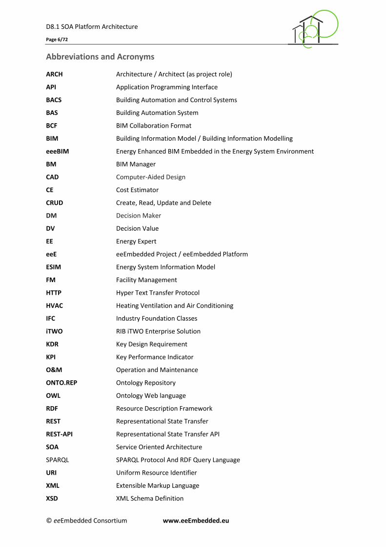
Abbreviations and Acronyms
ARCH Architecture / Architect (as project role)
API Application Programming Interface
BACS Building Automation and Control Systems
BAS Building Automation System
BCF BIM Collaboration Format
BIM Building Information Model / Building Information Modelling
eeeBIM Energy Enhanced BIM Embedded in the Energy System Environment
BM BIM Manager
CAD Computer-Aided Design
CE Cost Estimator
CRUD Create, Read, Update and Delete
DM Decision Maker
DV Decision Value
EE Energy Expert
eeE eeEmbedded Project / eeEmbedded Platform
ESIM Energy System Information Model
FM Facility Management
HTTP Hyper Text Transfer Protocol
HVAC Heating Ventilation and Air Conditioning
IFC Industry Foundation Classes
iTWO RIB iTWO Enterprise Solution
KDR Key Design Requirement
KPI Key Performance Indicator
O&M Operation and Maintenance
ONTO.REP Ontology Repository
OWL Ontology Web language
RDF Resource Description Framework
REST Representational State Transfer
REST-API Representational State Transfer API
SOA Service Oriented Architecture
SPARQL SPARQL Protocol And RDF Query Language
URI Uniform Resource Identifier
XML Extensible Markup Language
XSD XML Schema Definition
D8.1 SOA Platform Architecture
Page 7/72
© eeEmbedded Consortium www.eeEmbedded.eu
Acronyms of the Tools and Services in the eeEmbedded Platform
ALLPLAN The Architectural CAD system of Nemetschek Allplan used and extended within the eeEmbedded project
BIM-IT BCF Collaboration Service / BCF Collaboration Server
BIMFit BIM Filtering Service
BIM+ The Open BIM Cloud Repository of Nemetschek supporting both Nemetschek BIM+ and IFC based building modelling
DDS-CAD The M.E.P. CAD System of the Nemetschek Company DDS used and extended within the eeEmbedded project
EDM Jotne’s IFC (ISO 16739) and STEP (ISO 10303) Complient Cloud Repository
eeBACSWiz The eeBACSWizard Prototype Tool of SAUTER AG enabling BACS designer to find the correct set of BACS templates based on key design requirements already in the early design phase
ESD Energy System Designer
GD GRANLUND Designer (MEP / FM)
KPA Key Point Analysis Tool
LCC Life Cycle Costing Service integrated with RIB’s iTWO System
LCA Life Cycle Assessment Service integrated with RIB’s iTWO System
MAS Model Access Service
MCS Model Combiner Service
MMC Multi Model Container
MMNav Multi Model Navigator
MMS Model Manipulation Services
MVS Model Versioning Service
OAS Ontology Access Service
OMS Ontology Management Service
OVS Model Validator Service (Ontology-Based)
RAS Risk Analysis Service
SAS Stochastic Sampling Service
ScM Scenario Manager
SMM Simulation Model Mapper
SRM Simulation Results Manager
TMS Template Management Service
UMS User Management Service
3DTherm 3D Thermal CFD Analysis
3DWind 3D Wind CFD Analysis

D8.1 SOA Platform Architecture
Page 8/72
© eeEmbedded Consortium www.eeEmbedded.eu
Executive Summary
The objective of Deliverable 8.1 “SOA Platform Architecture” is to ensure the required flexibility of
services and tools in order to address the challenges of the eeEmbedded multi-model and multi-
services paltform. The outcome is the developed Service Oriented Architecture (SOA) based on and
extending the previous outcome from D1.5, which provides the principal architecture of the virtual
design lab and office and the definition of the overall interoperability requirements and scenario
workflows. In the course of the work for this deliverable the relevant schemata from D1.5 and D2.3
were significantly further developed and detailed. They cover the complex integration of multiple tools
into one system as well as their collaboration. All components and services are further examined to
enable reusability and configurability of the presented approach. Built around a core of collaboration
and management services and based on the ontology frameworks developed in WP5 (T5.1), WP6
(T6.1), and WP7 (T7.1), a common ICT structure is established, binding together (1) local off-the-shelve
applications such as CAD and FM systems, (2) distributed cloud-enabled computational tools, and (3) a
set of Multi Model and multi physics management web services via direct SOAP or REST interfaces.
Deliverable D8.1 is structured into ten chapters as follows:
The first chapter introduces the developed distributed SOA based on the conceptual plat-
form design presented in D1.5. The general principles of the architecture are explained
including a diagramatic representation of the communication between the different services
and tools via a common BCF-based service bus.
The second chapter outlines the eeEmbedded platform structure, emphasising the layer-
oriented approach defined in D1.5.
In the third chapter the different software components are discussed, providing the detailed
and updated ready-to-integrate modules of the platform, i.e. Authoring Tools, Collaboration
and Decision Support Tools, Multi Model Management Services, Simulation and Analysis
Services, Collaboration and Resource Management, Information Repositories and BIM Support.
The fourth chapter presents the refined scenario workflows from D1.5. They are extended to
include technical collaboration and information exchange challenges and allocated platform
modules with their specific tasks/subtasks into the generic scenarios.
The fifth, sixth and seventh chapter present reworked and extended sequence diagrams for
the urban, early and detailed design phase respectively based on the results from D2.3. As in
chapter four, the extended diagrams now include technical collaboration and information
exchange challenges and allocated platform modules with their specific tasks/subtasks.
The eighth chapter outlines the further detailing steps of the architecture with a usage
example from the Decision Making process (Use case 1, Task 1.7).
The ninth chapter describes the different platform APIs and the last tenth chapter presents
the conclusions drawn from the work done so far.
The work was led by RIB with great support from CIB, EPM, IABI and NEM. The content of the
deliverable was elaborated and discussed in frequent web conferences between all project partners.
In particular, the partners were involved in the R&D work as follows:
RIB: Work package leader, Task leader, Chapters 1-3, 9-11, report structure, overall editing
CIB: Contributions to chapters 2-9, 11 and report structuring
EPM: Contributions to chapters 1-4, 8 and 9
IAB: Contributions to chapters 3, 8, 9, 11
NEM: Contributions to chapters 3, 8, 9.
D8.1 SOA Platform Architecture
Page 9/72
© eeEmbedded Consortium www.eeEmbedded.eu
1 Introduction
In Deliverable D8.1 a distributed SOA platform is developed based on the conceptual architecture
outlined in D1.5 (Zellner et al. 2015). It supports the overall eeeBIM approach in terms of collabo-
ration and communication. The developed architecture separates services and tools into four distinct
categories: (1) Authoring and Decision Support Tools module, (2) Collaboration and Resource
Management module, (2) Simulation and Analysis Management module, and (4) Platform Core
module. These services and tools can be configured and adapted for various specialized virtual lab
realizations, whereby the core services provide the kernel for all such configurations. Communication
between the services and tools on the platform is realized strictly using the REST API (Richardson et
al. 2013), albeit a direct link from an authoring or decision support tools to a local simulation/analysis
tool is also possible. However, regardless of the underlying communication protocols used, a
coherent high level semantic BCF-API based on the buildingSmart collaboration format (Linhard et al.
2015) is uniformly defined and supported by all services. Thus, all services can be installed as
separate components, embedded in other end user tools or centrally used as web services.
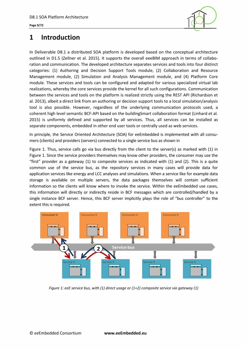
In principle, the Service Oriented Architecture (SOA) for eeEmbedded is implemented with all consu-
mers (clients) and providers (servers) connected to a single service bus as shown in
Figure 1. Thus, service calls go via bus directly from the client to the server(s) as marked with (1) in
Figure 1. Since the service providers themselves may know other providers, the consumer may use the
“first” provider as a gateway (1) to composite services as indicated with (1) and (2). This is a quite
common use of the service bus, as the repository services in many cases will provide data for
application services like energy and LCC analyses and simulations. When a service like for example data
storage is available on multiple servers, the data packages themselves will contain sufficient
information so the clients will know where to invoke the service. Within the eeEmbedded use cases,
this information will directly or indirectly reside in BCF messages which are controlled/handled by a
single instance BCF server. Hence, this BCF server implicitly plays the role of “bus controller” to the
extent this is required.
Service bus
Service X
Consumer X
Service X
Consumer XConsumer X
Service X
Consumer X
Service X
Consumer X
1 2
Figure 1: eeE service bus, with (1) direct usage or (1+2) composite service via gateway (1)
D8.1 SOA Platform Architecture
Page 10/72
© eeEmbedded Consortium www.eeEmbedded.eu
2 The eeEmbedded Platform
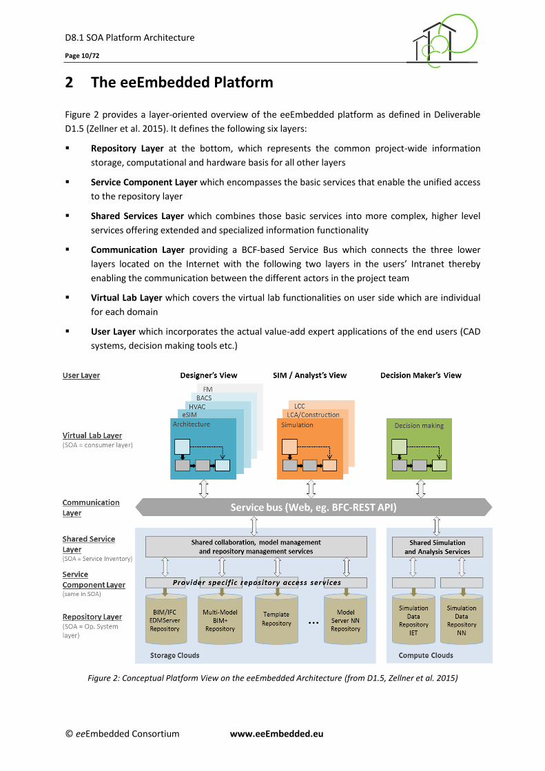
Figure 2 provides a layer-oriented overview of the eeEmbedded platform as defined in Deliverable
D1.5 (Zellner et al. 2015). It defines the following six layers:
Repository Layer at the bottom, which represents the common project-wide information
storage, computational and hardware basis for all other layers
Service Component Layer which encompasses the basic services that enable the unified access
to the repository layer
Shared Services Layer which combines those basic services into more complex, higher level
services offering extended and specialized information functionality
Communication Layer providing a BCF-based Service Bus which connects the three lower
layers located on the Internet with the following two layers in the users’ Intranet thereby
enabling the communication between the different actors in the project team
Virtual Lab Layer which covers the virtual lab functionalities on user side which are individual
for each domain
User Layer which incorporates the actual value-add expert applications of the end users (CAD
systems, decision making tools etc.)
Figure 2: Conceptual Platform View on the eeEmbedded Architecture (from D1.5, Zellner et al. 2015)

D8.1 SOA Platform Architecture
Page 11/72
© eeEmbedded Consortium www.eeEmbedded.eu
Within these layers, the following service types have been identified:
Local Apps, short for local applications, are executed and presented on the client’s hardware
Web Apps, short for Web applications, run partially or totally on a server while they are
displayed on the client’s hardware; They are typically accessed via a web browser but can also
be called by other web enabled tools or services such as the multi-model Navigator (mmNav)
or the platform’s Scenario Manager (ScM)
Services offer a set of functionalities or resources which can be included in other applications.;
Depending on their location or intention they can be further divided into:
o Libraries that can offer basic or even specialised functionalities like the model filtering
services BIMFit
o Cloud Services that are locate on distant servers (in the cloud) or offer access to them
o Collaboration Services offering collaboration functionalities
o Repository Services enabling the access to storage and management repositories
o Subservices which are addressed by other Services (e.g. the BIM--it User Management
Subservice UMS)
D8.1 SOA Platform Architecture
Page 12/72
© eeEmbedded Consortium www.eeEmbedded.eu
3 Software Components
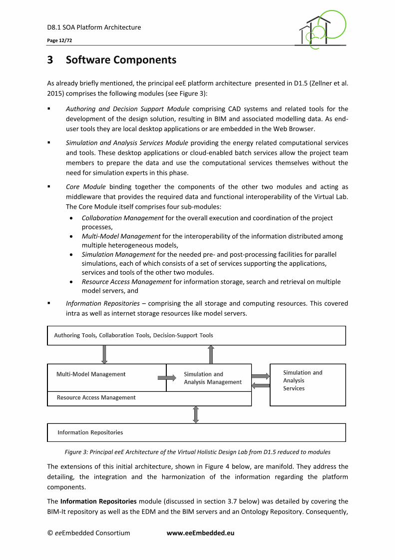
As already briefly mentioned, the principal eeE platform architecture presented in D1.5 (Zellner et al.
2015) comprises the following modules (see Figure 3):
Authoring and Decision Support Module comprising CAD systems and related tools for the
development of the design solution, resulting in BIM and associated modelling data. As end-
user tools they are local desktop applications or are embedded in the Web Browser.
Simulation and Analysis Services Module providing the energy related computational services
and tools. These desktop applications or cloud-enabled batch services allow the project team
members to prepare the data and use the computational services themselves without the
need for simulation experts in this phase.
Core Module binding together the components of the other two modules and acting as
middleware that provides the required data and functional interoperability of the Virtual Lab.
The Core Module itself comprises four sub-modules:
Collaboration Management for the overall execution and coordination of the project processes,
Multi-Model Management for the interoperability of the information distributed among multiple heterogeneous models,
Simulation Management for the needed pre- and post-processing facilities for parallel simulations, each of which consists of a set of services supporting the applications, services and tools of the other two modules.
Resource Access Management for information storage, search and retrieval on multiple model servers, and
Information Repositories – comprising the all storage and computing resources. This covered
intra as well as internet storage resources like model servers.
Figure 3: Principal eeE Architecture of the Virtual Holistic Design Lab from D1.5 reduced to modules
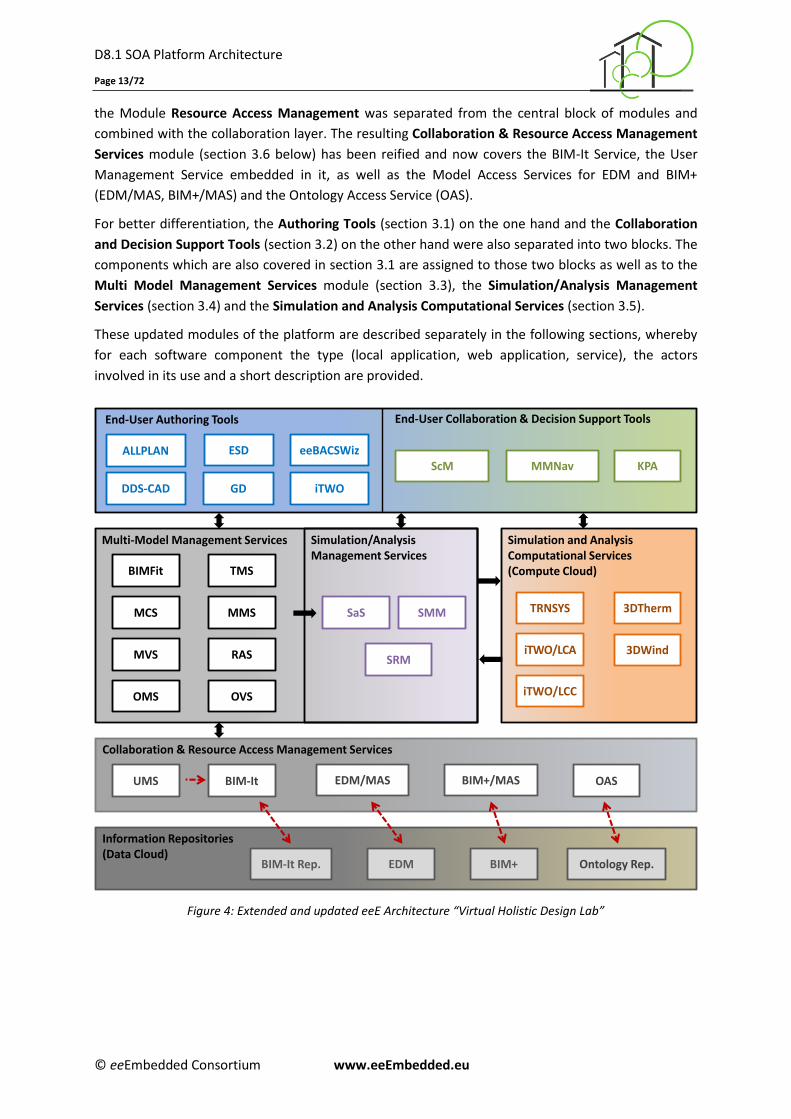
The extensions of this initial architecture, shown in Figure 4 below, are manifold. They address the
detailing, the integration and the harmonization of the information regarding the platform
components.
The Information Repositories module (discussed in section 3.7 below) was detailed by covering the
BIM-It repository as well as the EDM and the BIM servers and an Ontology Repository. Consequently,
D8.1 SOA Platform Architecture
Page 13/72
© eeEmbedded Consortium www.eeEmbedded.eu
the Module Resource Access Management was separated from the central block of modules and
combined with the collaboration layer. The resulting Collaboration & Resource Access Management
Services module (section 3.6 below) has been reified and now covers the BIM-It Service, the User
Management Service embedded in it, as well as the Model Access Services for EDM and BIM+
(EDM/MAS, BIM+/MAS) and the Ontology Access Service (OAS).
For better differentiation, the Authoring Tools (section 3.1) on the one hand and the Collaboration
and Decision Support Tools (section 3.2) on the other hand were also separated into two blocks. The
components which are also covered in section 3.1 are assigned to those two blocks as well as to the
Multi Model Management Services module (section 3.3), the Simulation/Analysis Management
Services (section 3.4) and the Simulation and Analysis Computational Services (section 3.5).
These updated modules of the platform are described separately in the following sections, whereby
for each software component the type (local application, web application, service), the actors
involved in its use and a short description are provided.
Figure 4: Extended and updated eeE Architecture “Virtual Holistic Design Lab”
End-User Authoring Tools
ALLPLAN
DDS-CAD
Multi-Model Management Services Simulation/Analysis Management Services
Simulation and Analysis Computational Services (Compute Cloud)
Collaboration & Resource Access Management Services
Information Repositories (Data Cloud)
3DTherm
3DWind
EDM/MAS
BIM+
BIMFit
BIM-It
EDM
BIM+/MAS
iTWO
ESD
GD
KPA
MCS
MMNav
MMS
MVS
OMS OVS
RAS
SaS SMM
SRM
UMS
ScM
TRNSYS
iTWO/LCA
iTWO/LCC
TMS
Ontology Rep.
End-User Collaboration & Decision Support Tools
OAS
BIM-It Rep.
eeBACSWiz
D8.1 SOA Platform Architecture
Page 14/72
© eeEmbedded Consortium www.eeEmbedded.eu
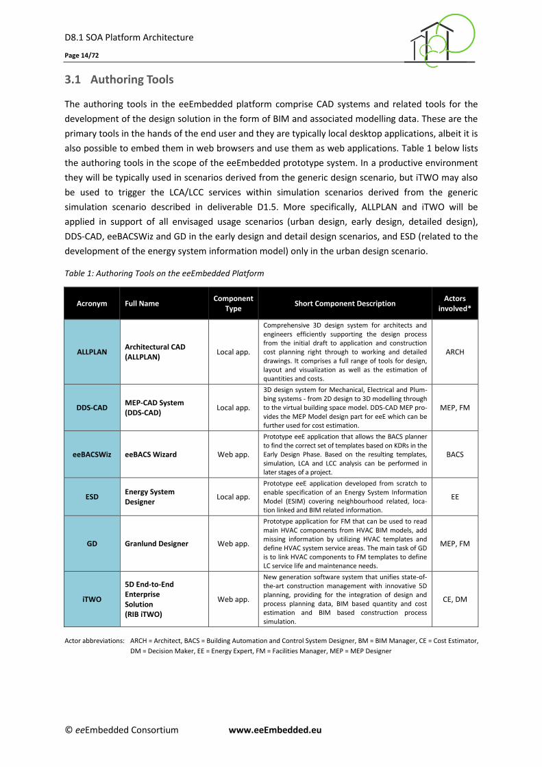
3.1 Authoring Tools
The authoring tools in the eeEmbedded platform comprise CAD systems and related tools for the
development of the design solution in the form of BIM and associated modelling data. These are the
primary tools in the hands of the end user and they are typically local desktop applications, albeit it is
also possible to embed them in web browsers and use them as web applications. Table 1 below lists
the authoring tools in the scope of the eeEmbedded prototype system. In a productive environment
they will be typically used in scenarios derived from the generic design scenario, but iTWO may also
be used to trigger the LCA/LCC services within simulation scenarios derived from the generic
simulation scenario described in deliverable D1.5. More specifically, ALLPLAN and iTWO will be
applied in support of all envisaged usage scenarios (urban design, early design, detailed design),
DDS-CAD, eeBACSWiz and GD in the early design and detail design scenarios, and ESD (related to the
development of the energy system information model) only in the urban design scenario.
Table 1: Authoring Tools on the eeEmbedded Platform
Acronym Full Name Component
Type Short Component Description
Actors involved*
ALLPLAN Architectural CAD (ALLPLAN)
Local app.
Comprehensive 3D design system for architects and engineers efficiently supporting the design process from the initial draft to application and construction cost planning right through to working and detailed drawings. It comprises a full range of tools for design, layout and visualization as well as the estimation of quantities and costs.
ARCH
DDS-CAD MEP-CAD System (DDS-CAD)
Local app.
3D design system for Mechanical, Electrical and Plum-bing systems - from 2D design to 3D modelling through to the virtual building space model. DDS-CAD MEP pro-vides the MEP Model design part for eeE which can be further used for cost estimation.
MEP, FM
eeBACSWiz eeBACS Wizard Web app.
Prototype eeE application that allows the BACS planner to find the correct set of templates based on KDRs in the Early Design Phase. Based on the resulting templates, simulation, LCA and LCC analysis can be performed in later stages of a project.
BACS
ESD Energy System Designer
Local app.
Prototype eeE application developed from scratch to enable specification of an Energy System Information Model (ESIM) covering neighbourhood related, loca-tion linked and BIM related information.
EE
GD Granlund Designer Web app.
Prototype application for FM that can be used to read main HVAC components from HVAC BIM models, add missing information by utilizing HVAC templates and define HVAC system service areas. The main task of GD is to link HVAC components to FM templates to define LC service life and maintenance needs.
MEP, FM
iTWO
5D End-to-End Enterprise Solution (RIB iTWO)
Web app.
New generation software system that unifies state-of-the-art construction management with innovative 5D planning, providing for the integration of design and process planning data, BIM based quantity and cost estimation and BIM based construction process simulation.
CE, DM
Actor abbreviations: ARCH = Architect, BACS = Building Automation and Control System Designer, BM = BIM Manager, CE = Cost Estimator,
DM = Decision Maker, EE = Energy Expert, FM = Facilities Manager, MEP = MEP Designer
D8.1 SOA Platform Architecture
Page 15/72
© eeEmbedded Consortium www.eeEmbedded.eu
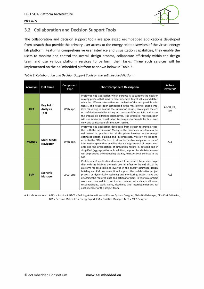
3.2 Collaboration and Decision Support Tools
The collaboration and decision support tools are specialized eeEmbedded applications developed
from scratch that provide the primary user access to the energy related services of the virtual energy
lab platform. Featuring comprehensive user interface and visualization capabilities, they enable the
users to monitor and control the overall design process, collaborate efficiently within the design
team and use various platform services to perform their tasks. Three such services will be
implemented on the eeEmbedded platform as shown below in Table 2.
Table 2: Collaboration and Decision Support Tools on the eeEmbedded Platform
Acronym Full Name Component
Type Short Component Description
Actors involved*
KPA Key Point Analysis Tool
Web app.
Prototype eeE application which purpose is to support the decision making process that aims to meet intended target values and deter-mine the different alternatives on the basis of the best possible solu-tion(s). The visualisation (embedded in the MMNav) will enable intu-itive reasoning to analyse the simulation results, investigate the eff-ects of design variables taking into account different KPIs and assess the impact on different alternatives. The graphical representation will use advanced visualisation techniques to provide for fast over-view and comparison of simulation results.
ARCH, EE, DM
MMNav Multi Model Navigator
Web app.
Prototype eeE application developed from scratch to provide, toge-ther with the eeE Scenario Manager, the main user interfaces to the eeE virtual lab platform for all disciplines involved in the energy-optimised design, building and FM processes. MMNav will be conn-ected to the BIM+ Platform to allow for flexible navigation in the nD information space thus enabling visual design control of project vari-ants and the presentation of simulation results in detailed and in simplified (aggregate) form. In addition, support for decision makers will be provided by embedding the Key Point Analysis Services in the GUI.
ALL
ScM Scenario Manager
Local app.
Prototype eeE application developed from scratch to provide, toge-ther with the MMNav the main user interface to the eeE virtual lab platform for all disciplines involved in the energy-optimised design, building and FM processes. It will support the collaborative project process by dynamically assigning and monitoring project tasks and attaching the required data and actions to them. In this way, project work can proceed in coordinated manner with clearly allocated responsibilities, work items, deadlines and interdependencies for each member of the project team.
ALL
Actor abbreviations: ARCH = Architect, BACS = Building Automation and Control System Designer, BM = BIM Manager, CE = Cost Estimator,
DM = Decision Maker, EE = Energy Expert, FM = Facilities Manager, MEP = MEP Designer
D8.1 SOA Platform Architecture
Page 16/72
© eeEmbedded Consortium www.eeEmbedded.eu
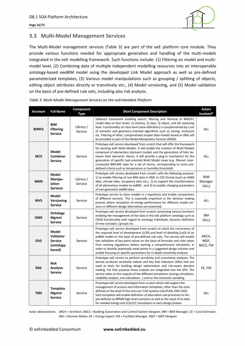
3.3 Multi-Model Management Services
The Multi-Model management services (Table 3) are part of the eeE platform core module. They
provide various functions needed for appropriate generation and handling of the multi-models
integrated in the eeE modelling framework. Such functions include: (1) Filtering on model and multi-
model level, (2) Combining data of multiple independent modelling resources into an interoperable
ontology-based eeeBIM model using the developed Link Model approach as well as pre-defined
parameterized templates, (3) Various model manipulations such as grouping / splitting of objects,
editing object attributes directly or transitively etc., (4) Model versioning, and (5) Model validation
on the basis of pre-defined rule sets, including also risk analysis.
Table 3: Multi-Model Management Services on the eeEmbedded Platform
Acronym Full Name Component
Type Short Component Description
Actors involved*
BIMFit BIM Filtering Service
Library / Service
Software framework enabling search, filtering and retrieval of BIM/IFC model data on four levels: 1) schema, 2) class, 3) object, and (4) reasoning level. Functionality on class level (view definition) is complemented by a set of semantic and geometry-oriented algorithms such as zoning, enclosure etc. Filtering of other, comparatively simpler data models based on XML will be provided as part of the Model Manipulator Services (MMS).
ALL
MCS Model Combiner Service
Service
Prototype eeE service developed from scratch that will offer the framework for working with Multi Models. It will enable the creation of Multi Models comprised of elementary (domain) models and the generation of links be-tween their elements. Hence, it will provide a plug-in mechanism for the generation of specific task-oriented Multi Model views (e.g. filtered, inter-connected BIM-BAS data for a set of rooms, corresponding to some pre-defined criteria such as temperature or humidity threshold).
ALL
MMS
Model Manipu-lation Services
Library / Service
Prototype eeE service developed from scratch with the following purpose: 1) to enable filtering of non-BIM data in XML or CSV format (such as GAEB data, climate data, occupancy data etc.), 2) to support the transformation of all elementary models to eeBIM , and 3) to enable changing parameters of non-geometric eeBIM data.
BIM Manager
(ALL)
MVS Model Versioning Service
Service
Prototype service to store models in a repository and enable comparisons of different versions. This is especially important in the decision making process where simulation of energy performance for different model ver-sions or different design alternatives are examined.
ALL
OMS Ontology Mgmnt Service
Service
Prototype eeE service developed from scratch comprising various functions enabling the management of the data in the eeE platform ontology such as CRUD functionality with regard to ontology individuals, dynamic definition of new concepts / groups etc.
BM (ALL)
OVS
Model Validator Service (ontology-based)
Service
Prototype eeE service developed from scratch to check the correctness of the required level of development (LOD) and level of detailing (LoD) of an eeBIM model on the basis of pre-defined rule sets. The service will enable fast validation of key point values on the basis of formulae and rules taken from existing regulations before starting a comprehensive simulation, in order to identify potentially weak points in a suggested design solution and enable focusing on specific parameters for in-depth sensitivity analyses.
ARCH, MEP,
BACS, FM
RAS Risk Analysis Service
Service
Prototype eeE service to perform sensitivity and uncertainty analyses. The service produces sensitivity indices and Key Risk Indicators (KRIs) that are used as basis for building design optimisation and risk-aware decision making. For that purpose those outputs are integrated into the KPA. The service relies on the outputs of the different simulations (energy simulation, reliability analysis, cost calculation...) and on the stochastic sampling.
EE, FM
TMS Template Mgmnt Service
Service
Prototype eeE service developed from scratch which will support the management of process and information templates, other than the ones defined on the level of the end-user CAD systems (ALLPLAN, DDS-CAD). Such templates will enable definition of alternative sub-processes to the pre-defined via BPMN high-level scenarios as well as the input of ee data for needed energy and LCA/LCC simulations in early design phases.
ALL
Actor abbreviations: ARCH = Architect, BACS = Building Automation and Control System Designer, BM = BIM Manager, CE = Cost Estimator,
DM = Decision Maker, EE = Energy Expert, FM = Facilities Manager, MEP = MEP Designer
D8.1 SOA Platform Architecture
Page 17/72
© eeEmbedded Consortium www.eeEmbedded.eu
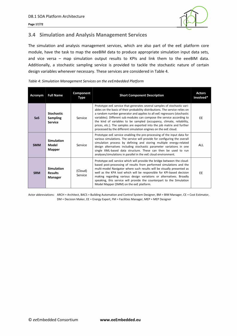
3.4 Simulation and Analysis Management Services
The simulation and analysis management services, which are also part of the eeE platform core
module, have the task to map the eeeBIM data to produce appropriate simulation input data sets,
and vice versa – map simulation output results to KPIs and link them to the eeeBIM data.
Additionally, a stochastic sampling service is provided to tackle the stochastic nature of certain
design variables whenever necessary. These services are considered in Table 4.
Table 4: Simulation Management Services on the eeEmbedded Platform
Acronym Full Name Component
Type Short Component Description
Actors involved*
SaS Stochastic Sampling Service
Service
Prototype eeE service that generates several samples of stochastic vari-ables on the basis of their probability distributions. The service relies on a random number generator and applies to all eeE regressors (stochastic variables). Different sub modules can compose the service according to the kind of variables to be sampled (occupancy, climate, reliability, prices, etc.). The samples are exported into the job matrix and further processed by the different simulation engines on the eeE cloud.
EE
SMM Simulation Model Mapper
Service
Prototype eeE service enabling the pre-processing of the input data for various simulations. The service will provide for configuring the overall simulation process by defining and storing multiple energy-related design alternatives including stochastic parameter variations in one single XML-based data structure. These can then be used to run analyses/simulations in parallel in the eeE cloud environment.
ALL
SRM Simulation Results Manager
(Cloud) Service
Prototype eeE service which will provide the bridge between the cloud-based post-processing of results from performed simulations and the multi-model Navigator where such results will be visually presented as well as the KPA tool which will be responsible for KPI-based decision making regarding various design variations or alternatives. Broadly speaking, this service will provide the counterpart to the Simulation Model Mapper (SMM) on the eeE platform.
EE
Actor abbreviations: ARCH = Architect, BACS = Building Automation and Control System Designer, BM = BIM Manager, CE = Cost Estimator,
DM = Decision Maker, EE = Energy Expert, FM = Facilities Manager, MEP = MEP Designer
D8.1 SOA Platform Architecture
Page 18/72
© eeEmbedded Consortium www.eeEmbedded.eu
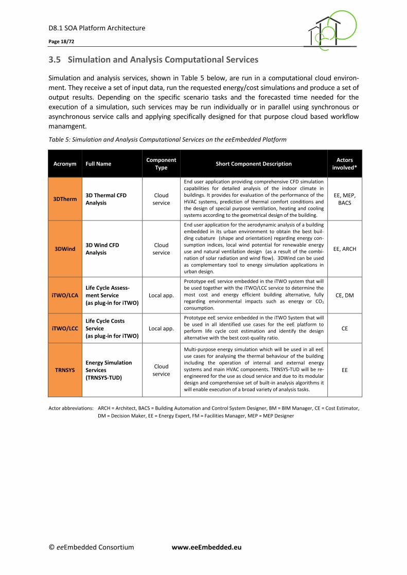
3.5 Simulation and Analysis Computational Services
Simulation and analysis services, shown in Table 5 below, are run in a computational cloud environ-
ment. They receive a set of input data, run the requested energy/cost simulations and produce a set of
output results. Depending on the specific scenario tasks and the forecasted time needed for the
execution of a simulation, such services may be run individually or in parallel using synchronous or
asynchronous service calls and applying specifically designed for that purpose cloud based workflow
manamgent.
Table 5: Simulation and Analysis Computational Services on the eeEmbedded Platform
Acronym Full Name Component
Type Short Component Description
Actors involved*
3DTherm 3D Thermal CFD Analysis
Cloud service
End user application providing comprehensive CFD simulation capabilities for detailed analysis of the indoor climate in buildings. It provides for evaluation of the performance of the HVAC systems, prediction of thermal comfort conditions and the design of special purpose ventilation, heating and cooling systems according to the geometrical design of the building.
EE, MEP, BACS
3DWind 3D Wind CFD Analysis
Cloud service
End user application for the aerodynamic analysis of a building embedded in its urban environment to obtain the best buil-ding cubature (shape and orientation) regarding energy con-sumption indices, local wind potential for renewable energy use and natural ventilation design (as a result of the combi-nation of solar radiation and wind flow). 3DWind can be used as complementary tool to energy simulation applications in urban design.
EE, ARCH
iTWO/LCA Life Cycle Assess-ment Service (as plug-in for iTWO)
Local app.
Prototype eeE service embedded in the iTWO system that will be used together with the iTWO/LCC service to determine the most cost and energy efficient building alternative, fully regarding environmental impacts such as energy or CO2 consumption.
CE, DM
iTWO/LCC Life Cycle Costs Service (as plug-in for iTWO)
Local app.
Prototype eeE service embedded in the iTWO System that will be used in all identified use cases for the eeE platform to perform life cycle cost estimation and identify the design alternative with the best cost-quality ratio.
CE
TRNSYS Energy Simulation Services (TRNSYS-TUD)
Cloud service
Multi-purpose energy simulation which will be used in all eeE use cases for analysing the thermal behaviour of the building including the operation of internal and external energy systems and main HVAC components. TRNSYS-TUD will be re-engineered for the use as cloud service and due to its modular design and comprehensive set of built-in analysis algorithms it will enable execution of a broad variety of analysis tasks.
EE
Actor abbreviations: ARCH = Architect, BACS = Building Automation and Control System Designer, BM = BIM Manager, CE = Cost Estimator,
DM = Decision Maker, EE = Energy Expert, FM = Facilities Manager, MEP = MEP Designer
D8.1 SOA Platform Architecture
Page 19/72
© eeEmbedded Consortium www.eeEmbedded.eu
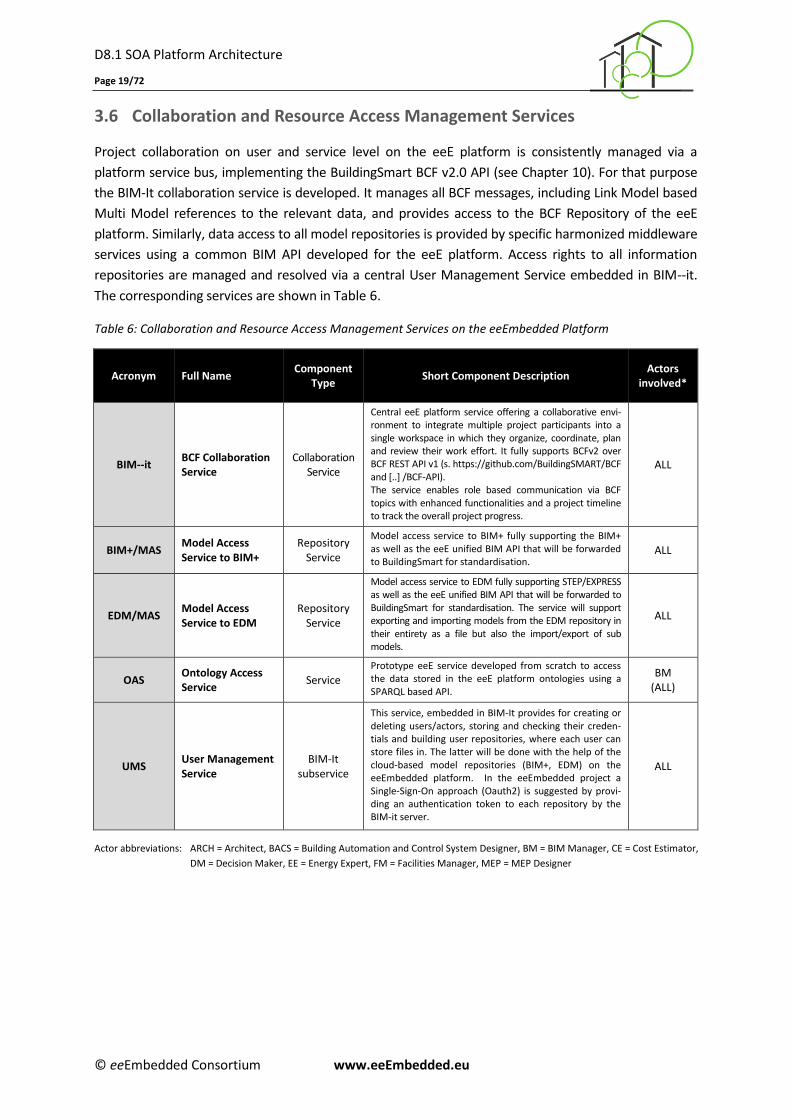
3.6 Collaboration and Resource Access Management Services
Project collaboration on user and service level on the eeE platform is consistently managed via a
platform service bus, implementing the BuildingSmart BCF v2.0 API (see Chapter 10). For that purpose
the BIM-It collaboration service is developed. It manages all BCF messages, including Link Model based
Multi Model references to the relevant data, and provides access to the BCF Repository of the eeE
platform. Similarly, data access to all model repositories is provided by specific harmonized middleware
services using a common BIM API developed for the eeE platform. Access rights to all information
repositories are managed and resolved via a central User Management Service embedded in BIM--it.
The corresponding services are shown in Table 6.
Table 6: Collaboration and Resource Access Management Services on the eeEmbedded Platform
Acronym Full Name Component
Type Short Component Description
Actors involved*
BIM--it BCF Collaboration Service
Collaboration Service
Central eeE platform service offering a collaborative envi-ronment to integrate multiple project participants into a single workspace in which they organize, coordinate, plan and review their work effort. It fully supports BCFv2 over BCF REST API v1 (s. https://github.com/BuildingSMART/BCF and [..] /BCF-API). The service enables role based communication via BCF topics with enhanced functionalities and a project timeline to track the overall project progress.
ALL
BIM+/MAS Model Access Service to BIM+
Repository Service
Model access service to BIM+ fully supporting the BIM+ as well as the eeE unified BIM API that will be forwarded to BuildingSmart for standardisation.
ALL
EDM/MAS Model Access Service to EDM
Repository Service
Model access service to EDM fully supporting STEP/EXPRESS as well as the eeE unified BIM API that will be forwarded to BuildingSmart for standardisation. The service will support exporting and importing models from the EDM repository in their entirety as a file but also the import/export of sub models.
ALL
OAS Ontology Access Service
Service Prototype eeE service developed from scratch to access the data stored in the eeE platform ontologies using a SPARQL based API.
BM (ALL)
UMS User Management Service
BIM-It subservice
This service, embedded in BIM-It provides for creating or deleting users/actors, storing and checking their creden-tials and building user repositories, where each user can store files in. The latter will be done with the help of the cloud-based model repositories (BIM+, EDM) on the eeEmbedded platform. In the eeEmbedded project a Single-Sign-On approach (Oauth2) is suggested by provi-ding an authentication token to each repository by the BIM-it server.
ALL
Actor abbreviations: ARCH = Architect, BACS = Building Automation and Control System Designer, BM = BIM Manager, CE = Cost Estimator,
DM = Decision Maker, EE = Energy Expert, FM = Facilities Manager, MEP = MEP Designer
D8.1 SOA Platform Architecture
Page 20/72
© eeEmbedded Consortium www.eeEmbedded.eu
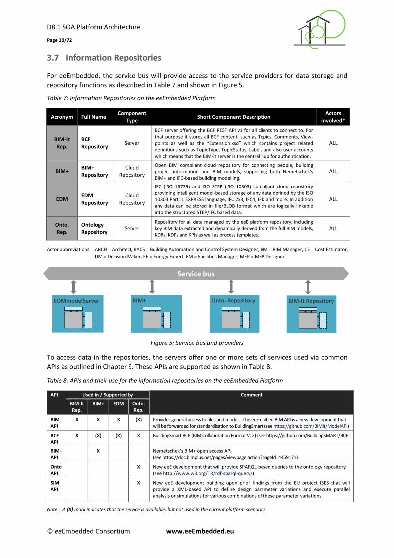
3.7 Information Repositories
For eeEmbedded, the service bus will provide access to the service providers for data storage and
repository functions as described in Table 7 and shown in Figure 5.
Table 7: Information Repositories on the eeEmbedded Platform
Acronym Full Name Component
Type Short Component Description
Actors involved*
BIM-It Rep.
BCF Repository
Server
BCF server offering the BCF REST API v1 for all clients to connect to. For that purpose it stores all BCF content, such as Topics, Comments, View-points as well as the “Extension.xsd” which contains project related definitions such as TopicType, TopicStatus, Labels and also user accounts which means that the BIM-it server is the central hub for authentication.
ALL
BIM+ BIM+ Repository
Cloud Repository
Open BIM compliant cloud repository for connecting people, building project information and BIM models, supporting both Nemetschek's BIM+ and IFC-based building modelling.
ALL
EDM EDM Repository
Cloud Repository
IFC (ISO 16739) and ISO STEP (ISO 10303) compliant cloud repository providing intelligent model-based storage of any data defined by the ISO 10303 Part11 EXPRESS language, IFC 2x3, IFC4, IFD and more. In addition any data can be stored in file/BLOB format which are logically linkable into the structured STEP/IFC based data.
ALL
Onto. Rep.
Ontology Repository
Server Repository for all data managed by the eeE platform repository, including key BIM data extracted and dynamically derived from the full BIM models, KDRs, KDPs and KPIs as well as process templates.
ALL
Actor abbreviations: ARCH = Architect, BACS = Building Automation and Control System Designer, BM = BIM Manager, CE = Cost Estimator,
DM = Decision Maker, EE = Energy Expert, FM = Facilities Manager, MEP = MEP Designer
Figure 5: Service bus and providers
To access data in the repositories, the servers offer one or more sets of services used via common
APIs as outlined in Chapter 9. These APIs are supported as shown in Table 8.
Table 8: APIs and their use for the information repositories on the eeEmbedded Platform
API Used in / Supported by Comment
BIM-It Rep.
BIM+ EDM Onto. Rep.
BIM API
X X X (X) Provides general access to files and models. The eeE unified BIM API is a new development that will be forwarded for standardisation to BuildingSmart (see https://github.com/BIMit/ModelAPI)
BCF API
X (X) (X) X BuildingSmart BCF (BIM Collaboration Format V. 2) (see https://github.com/BuildingSMART/BCF
BIM+ API
X Nemetschek’s BIM+ open access API (see https://doc.bimplus.net/pages/viewpage.action?pageId=4459171)
Onto API
X New eeE development that will provide SPARQL-based queries to the ontology repository (see http://www.w3.org/TR/rdf-sparql-query/)
SIM API
X New eeE development building upon prior findings from the EU project ISES that will provide a XML-based API to define design parameter variations and execute parallel analysis or simulations for various combinations of these parameter variations
Note: A (X) mark indicates that the service is available, but not used in the current platform scenarios.
Service bus
BIM+ BIM-It RepositoryEDMmodelServer Onto. Repository
D8.1 SOA Platform Architecture
Page 21/72
© eeEmbedded Consortium www.eeEmbedded.eu
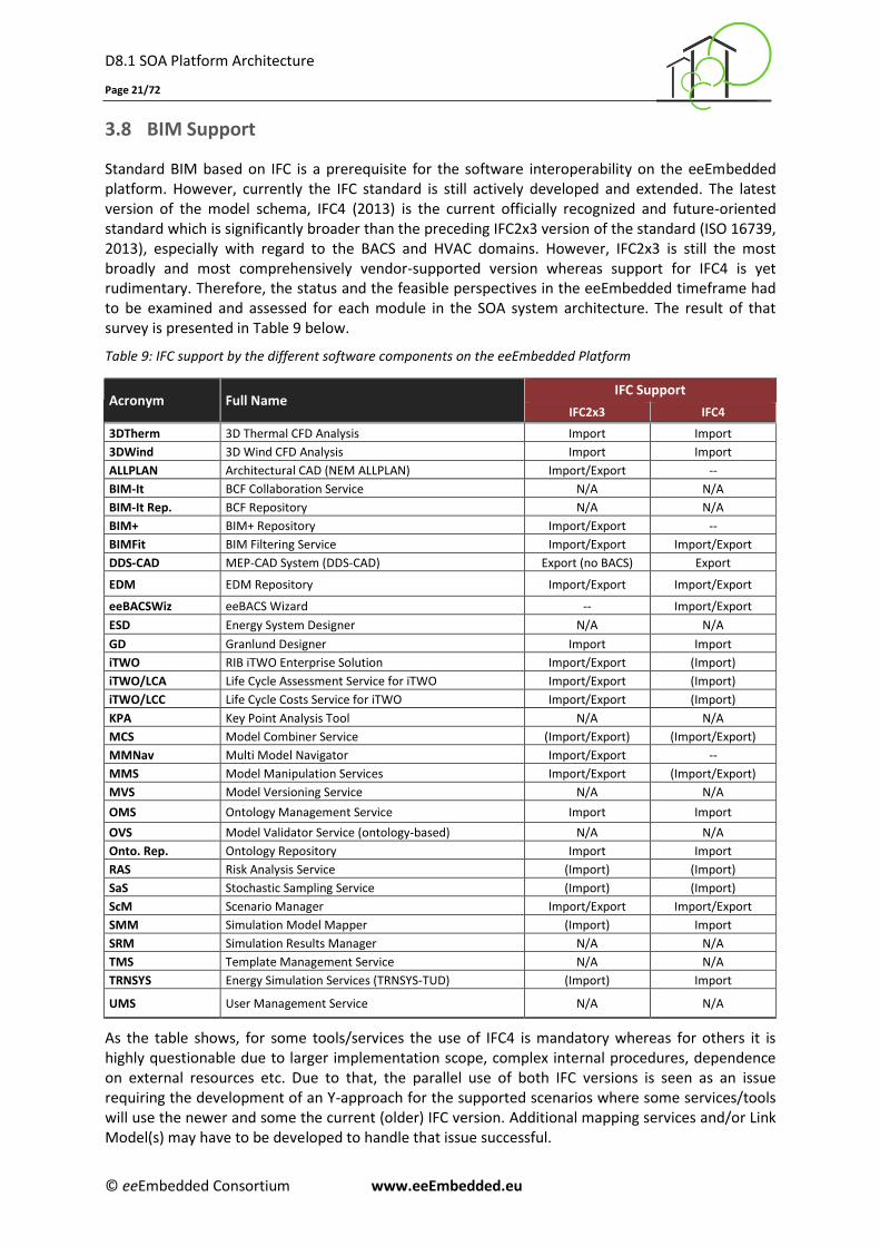
3.8 BIM Support
Standard BIM based on IFC is a prerequisite for the software interoperability on the eeEmbedded platform. However, currently the IFC standard is still actively developed and extended. The latest version of the model schema, IFC4 (2013) is the current officially recognized and future-oriented standard which is significantly broader than the preceding IFC2x3 version of the standard (ISO 16739, 2013), especially with regard to the BACS and HVAC domains. However, IFC2x3 is still the most broadly and most comprehensively vendor-supported version whereas support for IFC4 is yet rudimentary. Therefore, the status and the feasible perspectives in the eeEmbedded timeframe had to be examined and assessed for each module in the SOA system architecture. The result of that survey is presented in Table 9 below.
Table 9: IFC support by the different software components on the eeEmbedded Platform
Acronym Full Name IFC Support
IFC2x3 IFC4
3DTherm 3D Thermal CFD Analysis Import Import
3DWind 3D Wind CFD Analysis Import Import
ALLPLAN Architectural CAD (NEM ALLPLAN) Import/Export --
BIM-It BCF Collaboration Service N/A N/A
BIM-It Rep. BCF Repository N/A N/A
BIM+ BIM+ Repository Import/Export --
BIMFit BIM Filtering Service Import/Export Import/Export
DDS-CAD MEP-CAD System (DDS-CAD) Export (no BACS) Export
EDM EDM Repository Import/Export Import/Export
eeBACSWiz eeBACS Wizard -- Import/Export
ESD Energy System Designer N/A N/A
GD Granlund Designer Import Import
iTWO RIB iTWO Enterprise Solution Import/Export (Import)
iTWO/LCA Life Cycle Assessment Service for iTWO Import/Export (Import)
iTWO/LCC Life Cycle Costs Service for iTWO Import/Export (Import)
KPA Key Point Analysis Tool N/A N/A
MCS Model Combiner Service (Import/Export) (Import/Export)
MMNav Multi Model Navigator Import/Export --
MMS Model Manipulation Services Import/Export (Import/Export)
MVS Model Versioning Service N/A N/A
OMS Ontology Management Service Import Import
OVS Model Validator Service (ontology-based) N/A N/A
Onto. Rep. Ontology Repository Import Import
RAS Risk Analysis Service (Import) (Import)
SaS Stochastic Sampling Service (Import) (Import)
ScM Scenario Manager Import/Export Import/Export
SMM Simulation Model Mapper (Import) Import
SRM Simulation Results Manager N/A N/A
TMS Template Management Service N/A N/A
TRNSYS Energy Simulation Services (TRNSYS-TUD) (Import) Import
UMS User Management Service N/A N/A
As the table shows, for some tools/services the use of IFC4 is mandatory whereas for others it is highly questionable due to larger implementation scope, complex internal procedures, dependence on external resources etc. Due to that, the parallel use of both IFC versions is seen as an issue requiring the development of an Y-approach for the supported scenarios where some services/tools will use the newer and some the current (older) IFC version. Additional mapping services and/or Link Model(s) may have to be developed to handle that issue successful.
D8.1 SOA Platform Architecture
Page 22/72
© eeEmbedded Consortium www.eeEmbedded.eu
4 Scenario Workflows
4.1 Overview
Using both a conceptual top-down and a practice-related bottom-up approach four generic scenarios
covering
the platform set up,
the design domain,
the simulation and analysis domain, and
a generalized decision making process have been defined in D1.5 (Zellner et al. 2015).
On that basis, over thirty concretely detailed scenario workflows were defined in D2.3 (Guruz et al.
2015), presenting the specific processes related to Urban Design, Early Design and Detailed Design
that will be supported by the eeE platform. What was yet missing in these specifications were:
(1) Technical refinements and adjustments regarding the specific implementation considerations of
the SOA approach,
(2) Extensions regarding the technical collaboration and information exchange issues related to the
use of BCF as primary collaboration format,
(3) Appropriate consideration of the adopted Link Model / Multi-Model Container approach,
(4) the use of Ontologies and related ontology management and validation services, and
(5) the allocation of specific software components to each specific task and information exchange
within the scenarios.
These extensions and refinements of the original UML sequence diagrams from D1.5 and D2.3 are
presented in this and the following three chapters. In order to leave the overall appearance of the
diagrams unchanged (for easier comparison and recognition of the original diagram layout) no new
swimlanes for each of the defined platform services and tools have been introduced. Hence, only the
original categorisation in Design tools, Decision Support tools, Management services and Simulation
and Analysis services is shown. To indicate which component is used at which specific task and
information transfer, for each such task (shown with a respective arrow in the UML sequence
diagrams) beside the task subject the tool/service acronym is provided in brackets*). Loops or jumps
back are shown with dashed lines to distinguish them clearly from the normal top-to-bottom
procedure. Additionally, at several places text boxes explaining certain specific issues or constraints
that cannot be formally represented on the diagrams are also included. At last, a difference to the
diagrams from D2.3 is also that all swim lanes (lifelines) are always shown in the same colour, i.e.
Design Modules in blue, Decision Support tools in green, Management services in grey, and Simlution
and Analysis services in orange. Key Points (KDRs, KPIs etc.) as well as information exchanges are not
directly related to the SOA of the platform and are therefore not further elaborated compared to
D2.3 and consequently omitted in the following diagramatic representations.
*) An exception to that is the case when a service only returns an acknowledgement that the requested task has been
successfully executed, but no other data is sent back to the calling service/tall. This is denoted by ‘Ack’.
D8.1 SOA Platform Architecture
Page 23/72
© eeEmbedded Consortium www.eeEmbedded.eu
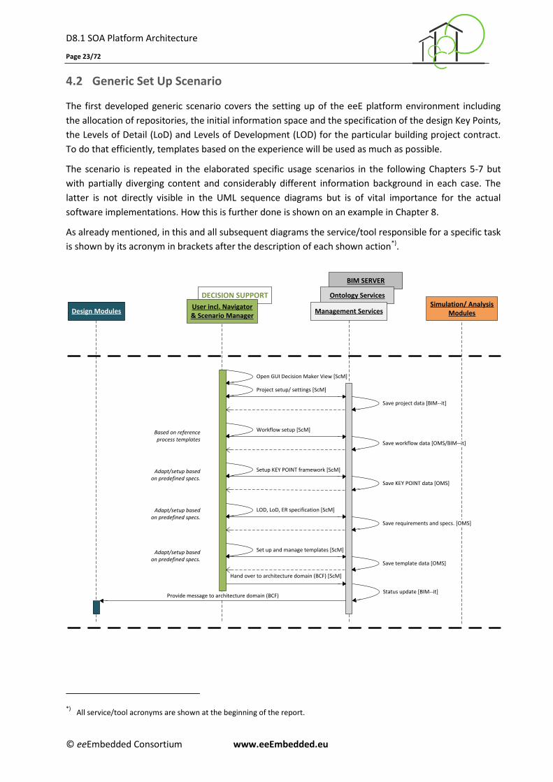
4.2 Generic Set Up Scenario
The first developed generic scenario covers the setting up of the eeE platform environment including
the allocation of repositories, the initial information space and the specification of the design Key Points,
the Levels of Detail (LoD) and Levels of Development (LOD) for the particular building project contract.
To do that efficiently, templates based on the experience will be used as much as possible.
The scenario is repeated in the elaborated specific usage scenarios in the following Chapters 5-7 but
with partially diverging content and considerably different information background in each case. The
latter is not directly visible in the UML sequence diagrams but is of vital importance for the actual
software implementations. How this is further done is shown on an example in Chapter 8.
As already mentioned, in this and all subsequent diagrams the service/tool responsible for a specific task
is shown by its acronym in brackets after the description of each shown action*).
Design ModulesSimulation/ Analysis
Modules
DECISION SUPPORT
BIM SERVER
Ontology Services
Management ServicesUser incl. Navigator& Scenario Manager
Project setup/ settings [ScM]
Setup KEY POINT framework [ScM]
LOD, LoD, ER specification [ScM]
Save project data [BIM--it]
Save workflow data [OMS/BIM--it]
Save KEY POINT data [OMS]
Save requirements and specs. [OMS]
Save template data [OMS]
Open GUI Decision Maker View [ScM]
Hand over to architecture domain (BCF) [ScM]
Status update [BIM--it]
Based on reference process templates
Adapt/setup based on predefined specs.
Adapt/setup based on predefined specs.
Adapt/setup based on predefined specs.
Workflow setup [ScM]
Provide message to architecture domain (BCF)
Set up and manage templates [ScM]
*) All service/tool acronyms are shown at the beginning of the report.
D8.1 SOA Platform Architecture
Page 24/72
© eeEmbedded Consortium www.eeEmbedded.eu
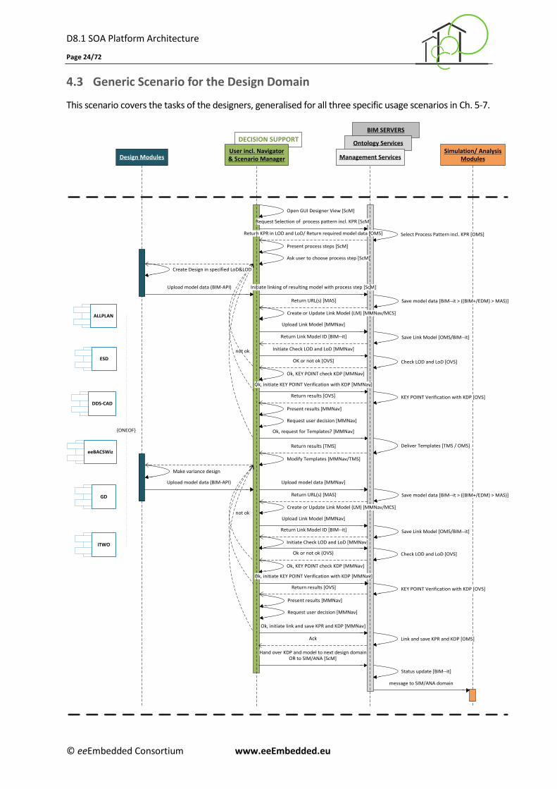
4.3 Generic Scenario for the Design Domain
This scenario covers the tasks of the designers, generalised for all three specific usage scenarios in Ch. 5-7.
DECISION SUPPORT
BIM SERVERS
Ontology Services
Design ModulesSimulation/ Analysis
Modules
Ok, KEY POINT check KDP [MMNav]
ALLPLAN
DDS-CAD
eeBACSWiz
GD
ESD
Open GUI Designer View [ScM]
Ok, initiate KEY POINT Verification with KDP [MMNav]
Ok, initiate link and save KPR and KDP [MMNav]
Ok, KEY POINT check KDP [MMNav]
not ok
Return KPR in LOD and LoD/ Return required model data [OMS]
KEY POINT Verification with KDP [OVS]
Ok, request for Templates? [MMNav]
Return results [TMS] Deliver Templates [TMS / OMS]
Modify Templates [MMNav/TMS]
Select Process Pattern incl. KPR [OMS]
Initiate Check LOD and LoD [MMNav]
OK or not ok [OVS]
Initiate Check LOD and LoD [MMNav]
Check LOD and LoD [OVS]
not ok
Check LOD and LoD [OVS]Ok or not ok (OVS)
Ok, initiate KEY POINT Verification with KDP [MMNav]
KEY POINT Verification with KDP [OVS]
Link and save KPR and KDP [OMS]Ack
Create or Update Link Model (LM) [MMNav/MCS]
Return Link Model ID [BIM--it]
Upload model data [MMNav]Upload model data (BIM-API)
Upload model data (BIM-API)
Return results [OVS]
Request user decision [MMNav]
Present results [MMNav]
OR to SIM/ANA [ScM]
Status update [BIM--it]
Request Selection of process pattern incl. KPR [ScM]
Present process steps [ScM]
Ask user to choose process step [ScM]
Create Design in specified LoD&LOD
Initiate linking of resulting model with process step [ScM]
Return URL(s) [MAS]
Upload Link Model [MMNav]
Save Link Model [OMS/BIM--it]
Create or Update Link Model (LM) [MMNav/MCS]
Save model data [BIM--it > ((BIM+/EDM) > MAS)]
Return Link Model ID [BIM--it]
Return URL(s) [MAS]
Upload Link Model [MMNav]
Save Link Model [OMS/BIM--it]
Make variance design
message to SIM/ANA domain
Return results [OVS]
Request user decision [MMNav]
Present results [MMNav]
Hand over KDP and model to next design domain
Management ServicesUser incl. Navigator& Scenario Manager
iTWO
{ONEOF}
Save model data [BIM--it > ((BIM+/EDM) > MAS)]
D8.1 SOA Platform Architecture
Page 25/72
© eeEmbedded Consortium www.eeEmbedded.eu
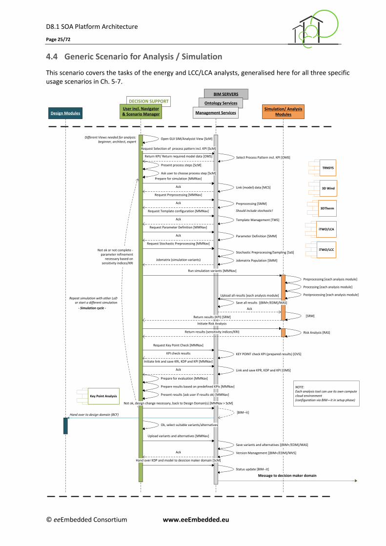
4.4 Generic Scenario for Analysis / Simulation
This scenario covers the tasks of the energy and LCC/LCA analysts, generalised here for all three specific usage scenarios in Ch. 5-7.
BIM SERVERS
Ontology ServicesDECISION SUPPORT
Management ServicesUser incl. Navigator& Scenario ManagerDesign Modules
Simulation/ AnalysisModules
Template Management [TMS]
Prepare for evaluation [MMNav]
TRNSYS
3D Wind
3DTherm
iTWO/LCA
Request Preprocessing [MMNav]
Upload all results [each analysis module]
Open GUI SIM/Analysist View [ScM]
Request Template configuration [MMNav]
Request Parameter Definition [MMNav]
Preprocessing [SMM]
Preprocessing [each analysis module]
Parameter Definition [SMM]
Processing [each analysis module]
Postprocessing [each analysis module]
Save variants and alternatives [(BIM+/EDM)/MAS]
Version Management [(BIM+/EDM)/MVS]Ack
[BIM--it]
Different Views needed for analysis: beginner, architect, expert
Ack
Jobmatrix (simulation variants)
Ack
Should include stochastic!
Save all results [(BIM+/EDM)/MAS]
KEY POINT check KPI (prepared results) [OVS]
Request Key Point Check [MMNav]
KPI check results
Link and save KPR, KDP and KPI [OMS]Ack
Message to decision maker domain
Hand over to design domain (BCF)
[SRM]
Status update [BIM--it]
Repeat simulation with other LoD or start a different simulation
- Simulation cycle -
Initiate link and save KRI, KDP and KPI [MMNav]
Prepare results based on predefined KPIs [MMNav]
Present results [ask user if results ok) [MMNav]
Ok, select suitable variants/alternatives
Upload variants and alternatives [MMNav]
Hand over KDP and model to desicion maker domain [ScM]
Run simulation variants [MMNav]
Return KPI/ Return required model data [OMS] Select Process Pattern incl. KPI [OMS]
Request Selection of process pattern incl. KPI [ScM]
Ack
Present process steps [ScM]
Ask user to choose process step [ScM]
Link (model) data [MCS]
Prepare for simulation [MMNav]
Ack
Key Point Analysis
NOTE:Each analysis tool can use its own compute cloud environment(configuration via BIM—it in setup phase)
Stochastic Preprocessing/Sampling [SaS]
Jobmatrix Population [SMM]
Ack
Request Stochastic Preprocessing [MMNav]
Risk Analysis [RAS]
Initiate Risk Analysis
Return results (sensitivity indices/KRI)
Return results (KPI) [SRM]
Not ok, design change necessary, back to Design Domain(s) [MMNav > ScM]
iTWO/LCCNot ok or not complete - parameter refinement
necessary based on sensitivity indices/KRI
D8.1 SOA Platform Architecture
Page 26/72
© eeEmbedded Consortium www.eeEmbedded.eu
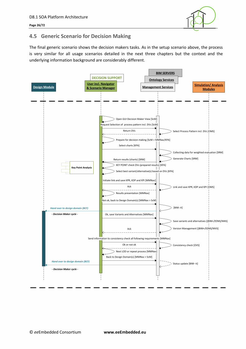
4.5 Generic Scenario for Decision Making
The final generic scenario shows the decision makers tasks. As in the setup scenario above, the process
is very similar for all usage scenarios detailed in the next three chapters but the context and the
underlying information background are considerably different.
DECISION SUPPORT
BIM SERVERS
Ontology ServicesUser incl. Navigator& Scenario ManagerDesign Module Management Services
Simulation/ AnalysisModules
Key Point Analysis
Select charts [KPA]
Return results (charts) [SRM]
Open GUI Decision Maker View [ScM]
Request Selection of process pattern incl. DVs [ScM]
Return DVs Select Process Pattern incl. DVs [OMS]
Collecting data for weighted evaluation [SRM]
Generate Charts [SRM]
Ok, save Variants and Alternatives [MMNav]
Next LOD or repeat process [MMNav]
Select best variant/alternative(s) based on DVs [KPA]
Send information to consistency check all following requirements [MMNav]
Ok or not ok
Not ok, back to Design Domain(s) [MMNav > ScM]
Prepare for decision making [ScM > MMNav/KPA]
Initiate link and save KPR, KDP and KPI [MMNav]
Link and save KPR, KDP and KPI [OMS]Ack
[BIM--it]
Ack
Consistency check [OVS]
Back to Design Domain(s) [MMNav > ScM]
Status update [BIM--it]Hand over to design domain (BCF)
Results presentation [MMNav]
- Decision Maker cycle -
- Decision Maker cycle -
KEY POINT check DVs (prepared results) [KPA]
Save variants and alternatives [(BIM+/EDM)/MAS]
Version Management [(BIM+/EDM)/MVS]
Hand over to design domain (BCF)
D8.1 SOA Platform Architecture
Page 27/72
© eeEmbedded Consortium www.eeEmbedded.eu
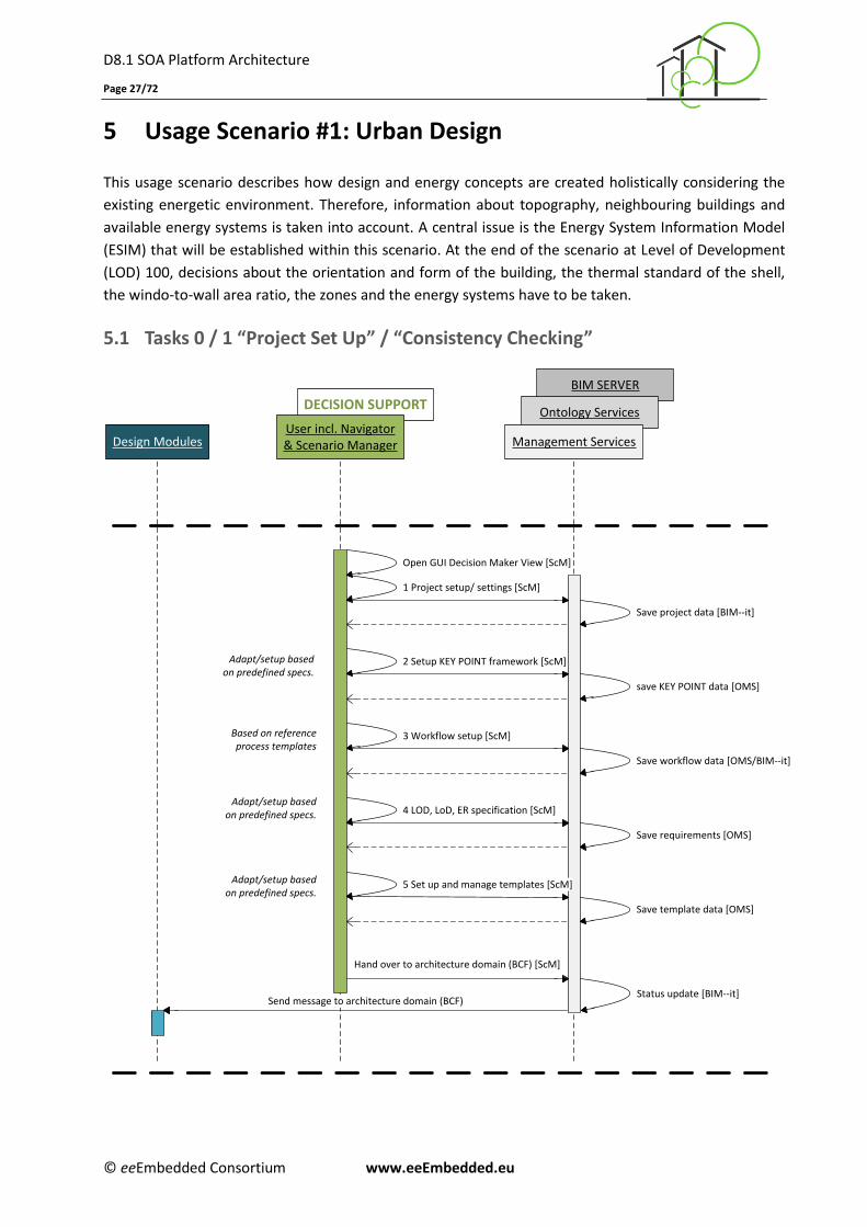
5 Usage Scenario #1: Urban Design
This usage scenario describes how design and energy concepts are created holistically considering the
existing energetic environment. Therefore, information about topography, neighbouring buildings and
available energy systems is taken into account. A central issue is the Energy System Information Model
(ESIM) that will be established within this scenario. At the end of the scenario at Level of Development
(LOD) 100, decisions about the orientation and form of the building, the thermal standard of the shell,
the windo-to-wall area ratio, the zones and the energy systems have to be taken.
5.1 Tasks 0 / 1 “Project Set Up” / “Consistency Checking”
DECISION SUPPORT
User incl. Navigator& Scenario Manager
BIM SERVER
Ontology Services
Management ServicesDesign Modules
Adapt/setup based on predefined specs.
1 Project setup/ settings [ScM]
2 Setup KEY POINT framework [ScM]
3 Workflow setup [ScM]
4 LOD, LoD, ER specification [ScM]
Save project data [BIM--it]
save KEY POINT data [OMS]
Save workflow data [OMS/BIM--it]
5 Set up and manage templates [ScM]
Save requirements [OMS]
Save template data [OMS]
Open GUI Decision Maker View [ScM]
Hand over to architecture domain (BCF) [ScM]
Status update [BIM--it]Send message to architecture domain (BCF)
Based on reference process templates
Adapt/setup based on predefined specs.
Adapt/setup based on predefined specs.
D8.1 SOA Platform Architecture
Page 28/72
© eeEmbedded Consortium www.eeEmbedded.eu
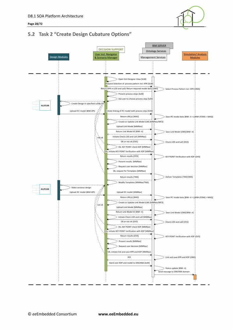
5.2 Task 2 “Create Design Cubature Options”
DECISION SUPPORT
BIM SERVER
Ontology Services
Design ModulesSimulation/ Analysis
ModulesUser incl. Navigator& Scenario Manager Management Services
Ok, KEY POINT check KDP [MMNav]
ALLPLAN
Open GUI Designer View [ScM]
Ok, initiate KEY POINT Verification with KDP [MMNav]
Ok, initiate link and save KPR and KDP [MMNav]
Ok, KEY POINT check KDP [MMNav]
not ok
Return KPR in LOD and LoD/ Return required model data [OMS]
KEY POINT Verification with KDP [OVS]
Ok, request for Templates [MMNav]
Return results [TMS] Deliver Templates [TMS/OMS]
Modify Templates [MMNav/TMS]
Select Process Pattern incl. KPR [OMS]
Initiate Check LOD and LoD [MMNav]
OK or not ok [OVS]
Initiate Check LOD and LoD [MMNav]
Check LOD and LoD [OVS]
not ok
Check LOD and LoD [OVS]Ok or not ok (OVS)
Ok, initiate KEY POINT Verification with KDP [MMNav]
KEY POINT Verification with KDP [OVS]
Link and save KPR and KDP [OMS]Ack
Create or Update Link Model (LM) [MMNav/MCS]
Save IFC model data [BIM--it > ((BIM+/EDM) > MAS)]
Return Link Model ID [BIM--it]
Upload IFC model [MMNav]Upload IFC model (BIM-API)
Upload IFC model (BIM-API)
Return results [OVS]
Request user decision [MMNav]
Present results. [MMNav]
Request Selection of process pattern incl. KPR [ScM]
Present process steps [ScM]
Ask user to choose process step [ScM]
Create Design in specified LoD&LOD
Initiate linking of IFC model with process step [SCM]
Return URL(s) [MAS]
Upload Link Model [MMNav]
Save Link Model [OMS/BIM--it]
Create or Update Link Model (LM) [MMNav/MCS]
Save IFC model data [BIM--it > ((BIM+/EDM) > MAS)]
Return Link Model ID [BIM--it]
Return URL(s) [MAS]
Upload Link Model [MMNav]
Save Link Model [OMS/BIM--it]
Make variance design
Return results [OVS]
Request user decision [MMNav]
Present results [MMNav]
ALLPLAN
Hand over KDP and model to SIM/ANA [ScM]
Send message to SIM/ANA domain
Status update [BIM--it]
D8.1 SOA Platform Architecture
Page 29/72
© eeEmbedded Consortium www.eeEmbedded.eu
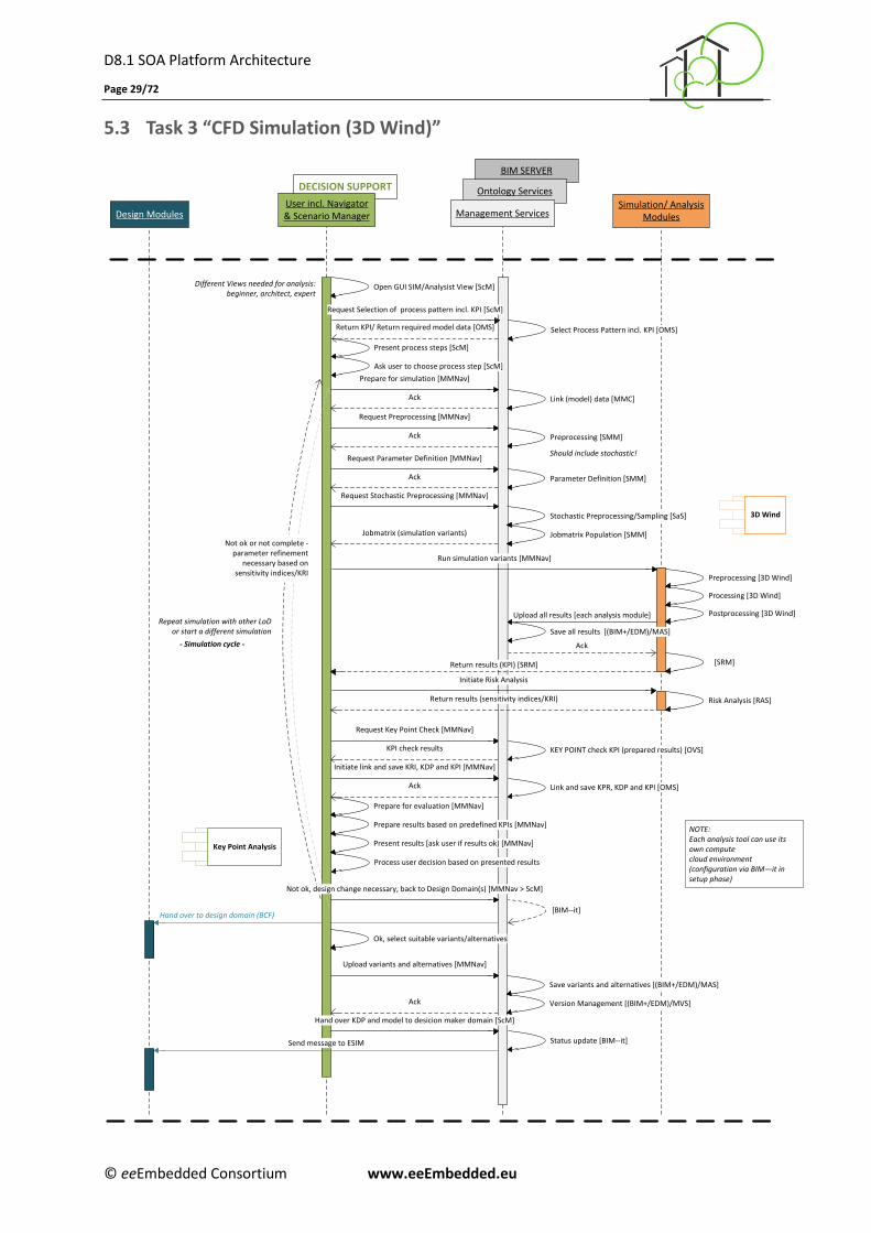
5.3 Task 3 “CFD Simulation (3D Wind)”
BIM SERVER
Ontology ServicesDECISION SUPPORT
Management ServicesUser incl. Navigator& Scenario ManagerDesign Modules
Simulation/ AnalysisModules
Prepare for evaluation [MMNav]
3D Wind
Request Preprocessing [MMNav]
Upload all results [each analysis module]
Open GUI SIM/Analysist View [ScM]
Request Parameter Definition [MMNav]
Preprocessing [SMM]
Preprocessing [3D Wind]
Parameter Definition [SMM]
Processing [3D Wind]
Postprocessing [3D Wind]
Ack
[BIM--it]
Different Views needed for analysis: beginner, architect, expert
Jobmatrix (simulation variants)
Ack
Should include stochastic!
Save all results [(BIM+/EDM)/MAS]
KEY POINT check KPI (prepared results) [OVS]
Request Key Point Check [MMNav]
KPI check results
Link and save KPR, KDP and KPI [OMS]Ack
Hand over to design domain (BCF)
[SRM]
Status update [BIM--it]
Repeat simulation with other LoD or start a different simulation
- Simulation cycle -
Initiate link and save KRI, KDP and KPI [MMNav]
Prepare results based on predefined KPIs [MMNav]
Present results [ask user if results ok) [MMNav]
Ok, select suitable variants/alternatives
Upload variants and alternatives [MMNav]
Hand over KDP and model to desicion maker domain [ScM]
Run simulation variants [MMNav]
Return KPI/ Return required model data [OMS] Select Process Pattern incl. KPI [OMS]
Request Selection of process pattern incl. KPI [ScM]
Ack
Present process steps [ScM]
Ask user to choose process step [ScM]
Link (model) data [MMC]
Prepare for simulation [MMNav]
Ack
Key Point Analysis
NOTE:Each analysis tool can use its own compute cloud environment(configuration via BIM—it in setup phase)
Stochastic Preprocessing/Sampling [SaS]
Jobmatrix Population [SMM]
Ack
Request Stochastic Preprocessing [MMNav]
Risk Analysis [RAS]
Initiate Risk Analysis
Return results (sensitivity indices/KRI)
Return results (KPI) [SRM]
Process user decision based on presented results
Not ok, design change necessary, back to Design Domain(s) [MMNav > ScM]
Send message to ESIM
Save variants and alternatives [(BIM+/EDM)/MAS]
Version Management [(BIM+/EDM)/MVS]
Not ok or not complete - parameter refinement
necessary based on sensitivity indices/KRI
D8.1 SOA Platform Architecture
Page 30/72
© eeEmbedded Consortium www.eeEmbedded.eu
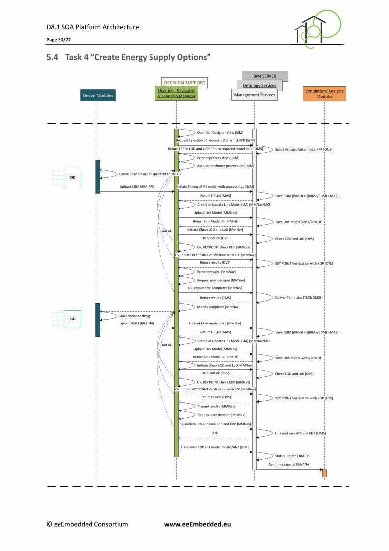
5.4 Task 4 “Create Energy Supply Options”
DECISION SUPPORT
BIM SERVER
Ontology Services
Design ModulesSimulation/ Analysis
ModulesManagement ServicesUser incl. Navigator& Scenario Manager
Ok, KEY POINT check KDP [MMNav]
ESD
Open GUI Designer View [ScM]
Ok, initiate KEY POINT Verification with KDP [MMNav]
Ok, initiate link and save KPR and KDP [MMNav]
Ok, KEY POINT check KDP [MMNav]
not ok
Return KPR in LOD and LoD/ Return required model data [OMS]
KEY POINT Verification with KDP [OVS]
Ok, request for Templates [MMNav]
Return results [TMS] Deliver Templates [TMS/OMS]
Modify Templates [MMNav]
Select Process Pattern incl. KPR [OMS]
Initiate Check LOD and LoD [MMNav]
OK or not ok [OVS]
Initiate Check LOD and LoD [MMNav]
Check LOD and LoD [OVS]
not ok
Check LOD and LoD [OVS]Ok or not ok (OVS)
Ok, initiate KEY POINT Verification with KDP [MMNav]
KEY POINT Verification with KDP [OVS]
Link and save KPR and KDP [OMS]Ack
Create or Update Link Model (LM) [MMNav/MCS]
Save ESIM [BIM--it > ((BIM+/EDM) > MAS)]
Return Link Model ID [BIM--it]
Upload ESIM model data [MMNav]Upload ESIM (BIM-API)
Upload ESIM (BIM-API)
Return results [OVS]
Request user decision [MMNav]
Present results. [MMNav]
Hand over KDP and model to SIM/ANA [ScM]
Status update [BIM--it]
Request Selection of process pattern incl. KPR [ScM]
Present process steps [ScM]
Ask user to choose process step [ScM]
Create ESIM Design in specified LoD&LOD
Initiate linking of IFC model with process step [ScM]
Return URL(s) [MAS]
Upload Link Model [MMNav]
Save Link Model [OMS/BIM--it]
Create or Update Link Model (LM) [MMNav/MCS]
Save ESIM [BIM--it > ((BIM+/EDM) > MAS)]
Return Link Model ID [BIM--it]
Return URL(s) [MAS]
Upload Link Model [MMNav]
Save Link Model [OMS/BIM--it]
Make variance design
Send message to SIM/ANA
Return results [OVS]
Request user decision [MMNav]
Present results [MMNav]
ESD
D8.1 SOA Platform Architecture
Page 31/72
© eeEmbedded Consortium www.eeEmbedded.eu
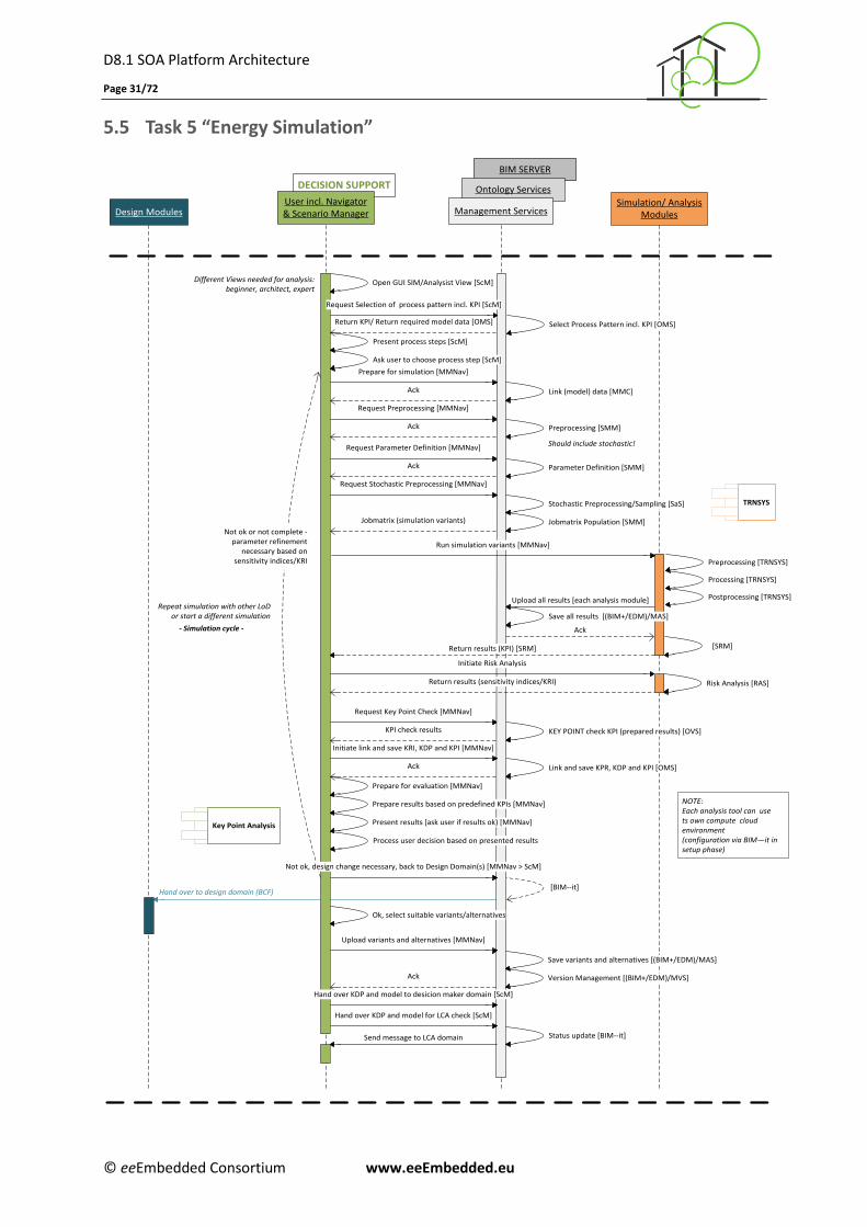
5.5 Task 5 “Energy Simulation”
DECISION SUPPORT
User incl. Navigator& Scenario ManagerDesign Modules
Simulation/ AnalysisModules
Different Views needed for analysis: beginner, architect, expert
BIM SERVER
Ontology Services
Management Services
Prepare for evaluation [MMNav]
TRNSYS
Request Preprocessing [MMNav]
Upload all results [each analysis module]
Open GUI SIM/Analysist View [ScM]
Request Parameter Definition [MMNav]
Preprocessing [SMM]
Parameter Definition [SMM]
Ack
[BIM--it]
Jobmatrix (simulation variants)
Ack
Should include stochastic!
Save all results [(BIM+/EDM)/MAS]
KEY POINT check KPI (prepared results) [OVS]
Request Key Point Check [MMNav]
KPI check results
Link and save KPR, KDP and KPI [OMS]Ack
Hand over to design domain (BCF)
[SRM]
Repeat simulation with other LoD or start a different simulation
- Simulation cycle -
Initiate link and save KRI, KDP and KPI [MMNav]
Prepare results based on predefined KPIs [MMNav]
Present results [ask user if results ok) [MMNav]
Ok, select suitable variants/alternatives
Upload variants and alternatives [MMNav]
Hand over KDP and model to desicion maker domain [ScM]
Run simulation variants [MMNav]
Return KPI/ Return required model data [OMS] Select Process Pattern incl. KPI [OMS]
Request Selection of process pattern incl. KPI [ScM]
Ack
Present process steps [ScM]
Ask user to choose process step [ScM]
Link (model) data [MMC]
Prepare for simulation [MMNav]
Ack
Key Point Analysis
NOTE:Each analysis tool can use ts own compute cloud environment(configuration via BIM—it in setup phase)
Stochastic Preprocessing/Sampling [SaS]
Jobmatrix Population [SMM]
Ack
Request Stochastic Preprocessing [MMNav]
Risk Analysis [RAS]
Initiate Risk Analysis
Return results (sensitivity indices/KRI)
Return results (KPI) [SRM]
Process user decision based on presented results
Not ok, design change necessary, back to Design Domain(s) [MMNav > ScM]
Hand over KDP and model for LCA check [ScM]
Send message to LCA domain Status update [BIM--it]
Save variants and alternatives [(BIM+/EDM)/MAS]
Version Management [(BIM+/EDM)/MVS]
Preprocessing [TRNSYS]
Processing [TRNSYS]
Postprocessing [TRNSYS]
Not ok or not complete - parameter refinement
necessary based on sensitivity indices/KRI
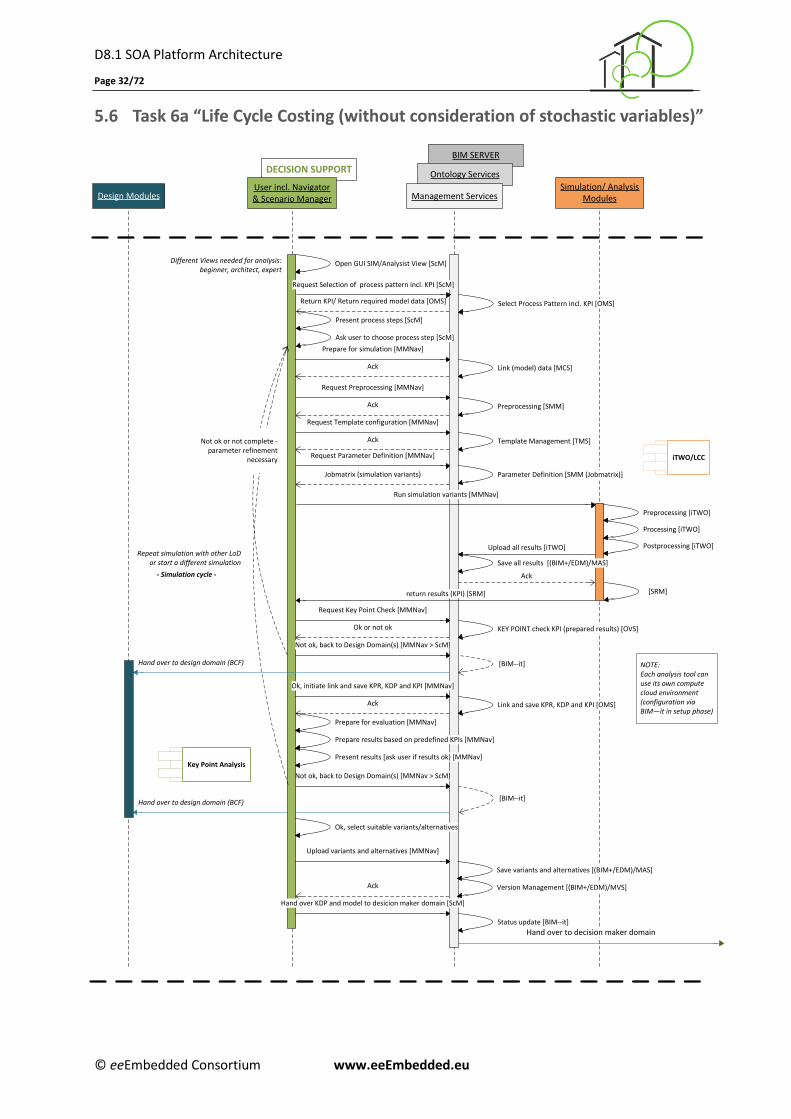
D8.1 SOA Platform Architecture
Page 32/72
© eeEmbedded Consortium www.eeEmbedded.eu
5.6 Task 6a “Life Cycle Costing (without consideration of stochastic variables)”
Design ModulesSimulation/ Analysis
Modules
Hand over to decision maker domain
NOTE:Each analysis tool can use its own compute cloud environment(configuration via BIM—it in setup phase)
BIM SERVER
Ontology ServicesDECISION SUPPORT
User incl. Navigator& Scenario Manager Management Services
Template Management [TMS]
Prepare for evaluation [MMNav]
iTWO/LCC
Request Preprocessing [MMNav]
Upload all results [iTWO]
Open GUI SIM/Analysist View [ScM]
Request Template configuration [MMNav]
Request Parameter Definition [MMNav]
Preprocessing [SMM]
Preprocessing [iTWO]
Parameter Definition [SMM (Jobmatrix)]
Processing [iTWO]
Postprocessing [iTWO]
Ack
Not ok, back to Design Domain(s) [MMNav > ScM]
[BIM--it]
Different Views needed for analysis: beginner, architect, expert
Ack
Jobmatrix (simulation variants)
Ack
Save all results [(BIM+/EDM)/MAS]
KEY POINT check KPI (prepared results) [OVS]
Request Key Point Check [MMNav]
Ok or not ok
Link and save KPR, KDP and KPI [OMS]Ack
Hand over to design domain (BCF)
[SRM]
Status update [BIM--it]
Repeat simulation with other LoD or start a different simulation
- Simulation cycle -
Ok, initiate link and save KPR, KDP and KPI [MMNav]
Prepare results based on predefined KPIs [MMNav]
Present results [ask user if results ok) [MMNav]
Ok, select suitable variants/alternatives
Upload variants and alternatives [MMNav]
Hand over KDP and model to desicion maker domain [ScM]
Run simulation variants [MMNav]
Return KPI/ Return required model data [OMS] Select Process Pattern incl. KPI [OMS]
Request Selection of process pattern incl. KPI [ScM]
Ack
Present process steps [ScM]
Ask user to choose process step [ScM]
Link (model) data [MCS]
Prepare for simulation [MMNav]
Ack
Key Point Analysis
Not ok, back to Design Domain(s) [MMNav > ScM]
[BIM--it]Hand over to design domain (BCF)
Save variants and alternatives [(BIM+/EDM)/MAS]
Version Management [(BIM+/EDM)/MVS]
return results (KPI) [SRM]
Not ok or not complete - parameter refinement
necessary
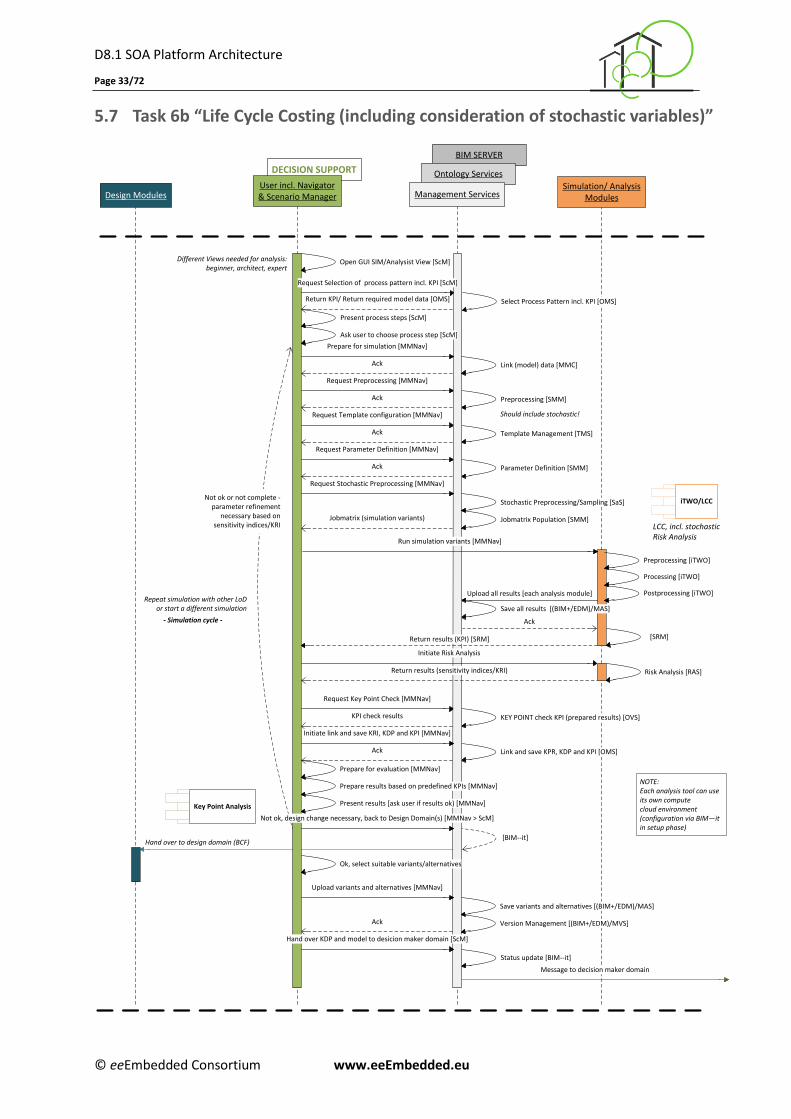
D8.1 SOA Platform Architecture
Page 33/72
© eeEmbedded Consortium www.eeEmbedded.eu
5.7 Task 6b “Life Cycle Costing (including consideration of stochastic variables)”
BIM SERVER
Ontology ServicesDECISION SUPPORT
Management ServicesUser incl. Navigator& Scenario ManagerDesign Modules
Simulation/ AnalysisModules
Template Management [TMS]
Prepare for evaluation [MMNav]
iTWO/LCC
Request Preprocessing [MMNav]
Upload all results [each analysis module]
Open GUI SIM/Analysist View [ScM]
Request Template configuration [MMNav]
Request Parameter Definition [MMNav]
Preprocessing [SMM]
Parameter Definition [SMM]
Ack
[BIM--it]
Different Views needed for analysis: beginner, architect, expert
Ack
Jobmatrix (simulation variants)
Ack
Should include stochastic!
Save all results [(BIM+/EDM)/MAS]
KEY POINT check KPI (prepared results) [OVS]
Request Key Point Check [MMNav]
KPI check results
Link and save KPR, KDP and KPI [OMS]Ack
Message to decision maker domain
Hand over to design domain (BCF)
[SRM]
Status update [BIM--it]
Repeat simulation with other LoD or start a different simulation
- Simulation cycle -
Initiate link and save KRI, KDP and KPI [MMNav]
Prepare results based on predefined KPIs [MMNav]
Present results [ask user if results ok) [MMNav]
Ok, select suitable variants/alternatives
Upload variants and alternatives [MMNav]
Hand over KDP and model to desicion maker domain [ScM]
Run simulation variants [MMNav]
Return KPI/ Return required model data [OMS] Select Process Pattern incl. KPI [OMS]
Request Selection of process pattern incl. KPI [ScM]
Ack
Present process steps [ScM]
Ask user to choose process step [ScM]
Link (model) data [MMC]
Prepare for simulation [MMNav]
Ack
Key Point Analysis
NOTE:Each analysis tool can use its own compute cloud environment(configuration via BIM—it in setup phase)
Stochastic Preprocessing/Sampling [SaS]
Jobmatrix Population [SMM]
Ack
Request Stochastic Preprocessing [MMNav]
Risk Analysis [RAS]
Initiate Risk Analysis
Return results (sensitivity indices/KRI)
Return results (KPI) [SRM]
Not ok, design change necessary, back to Design Domain(s) [MMNav > ScM]
Save variants and alternatives [(BIM+/EDM)/MAS]
Version Management [(BIM+/EDM)/MVS]
Preprocessing [iTWO]
Processing [iTWO]
Postprocessing [iTWO]
LCC, incl. stochastic Risk Analysis
Not ok or not complete - parameter refinement
necessary based on sensitivity indices/KRI
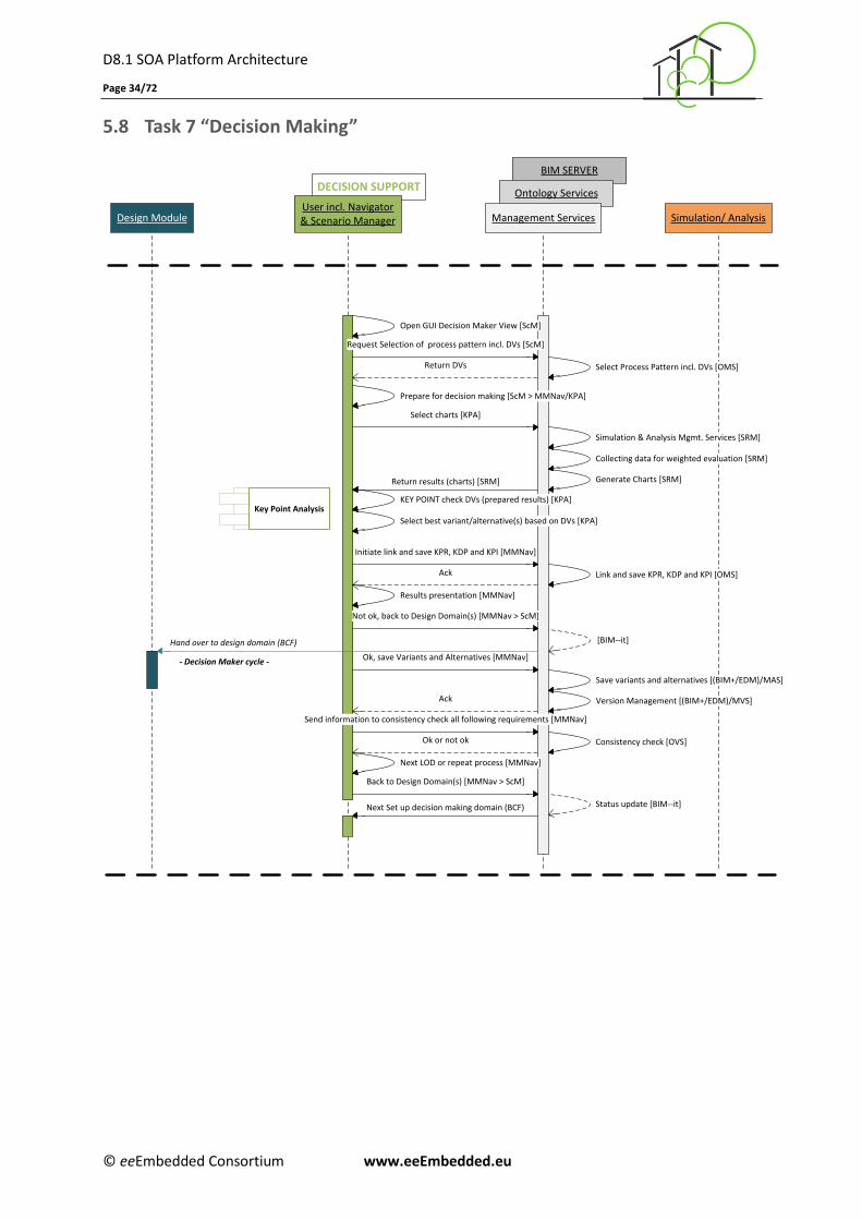
D8.1 SOA Platform Architecture
Page 34/72
© eeEmbedded Consortium www.eeEmbedded.eu
5.8 Task 7 “Decision Making”
DECISION SUPPORT
BIM SERVER
Ontology ServicesUser incl. Navigator& Scenario ManagerDesign Module Management Services Simulation/ Analysis
Key Point Analysis
Select charts [KPA]
Return results (charts) [SRM]
Open GUI Decision Maker View [ScM]
Request Selection of process pattern incl. DVs [ScM]
Return DVs Select Process Pattern incl. DVs [OMS]
Simulation & Analysis Mgmt. Services [SRM]
Collecting data for weighted evaluation [SRM]
Generate Charts [SRM]
Ok, save Variants and Alternatives [MMNav]
Next LOD or repeat process [MMNav]
KEY POINT check DVs (prepared results) [KPA]
Send information to consistency check all following requirements [MMNav]
Ok or not ok
Not ok, back to Design Domain(s) [MMNav > ScM]
Prepare for decision making [ScM > MMNav/KPA]
Initiate link and save KPR, KDP and KPI [MMNav]
Link and save KPR, KDP and KPI [OMS]Ack
[BIM--it]
Ack
Consistency check [OVS]
Back to Design Domain(s) [MMNav > ScM]
Status update [BIM--it]
Hand over to design domain (BCF)
Results presentation [MMNav]
- Decision Maker cycle -
Select best variant/alternative(s) based on DVs [KPA]
Next Set up decision making domain (BCF)
Save variants and alternatives [(BIM+/EDM)/MAS]
Version Management [(BIM+/EDM)/MVS]
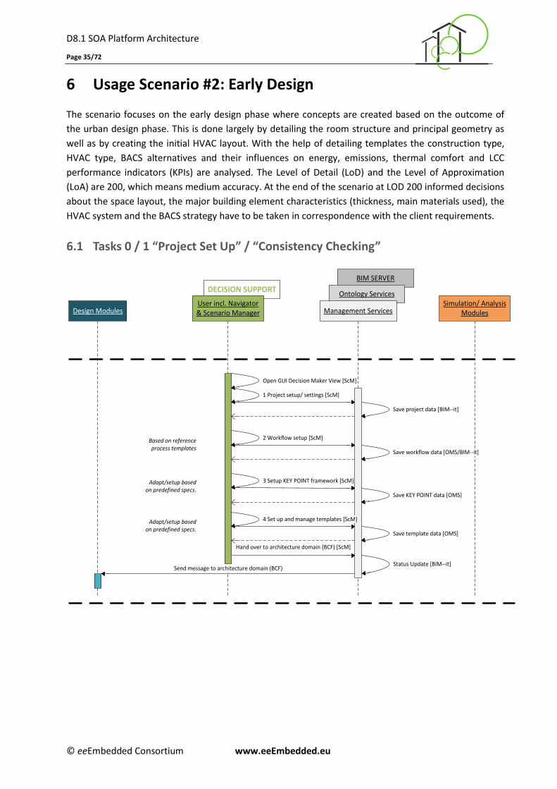
D8.1 SOA Platform Architecture
Page 35/72
© eeEmbedded Consortium www.eeEmbedded.eu
6 Usage Scenario #2: Early Design
The scenario focuses on the early design phase where concepts are created based on the outcome of
the urban design phase. This is done largely by detailing the room structure and principal geometry as
well as by creating the initial HVAC layout. With the help of detailing templates the construction type,
HVAC type, BACS alternatives and their influences on energy, emissions, thermal comfort and LCC
performance indicators (KPIs) are analysed. The Level of Detail (LoD) and the Level of Approximation
(LoA) are 200, which means medium accuracy. At the end of the scenario at LOD 200 informed decisions
about the space layout, the major building element characteristics (thickness, main materials used), the
HVAC system and the BACS strategy have to be taken in correspondence with the client requirements.
6.1 Tasks 0 / 1 “Project Set Up” / “Consistency Checking”
1 Project setup/ settings [ScM]
Design ModulesSimulation/ Analysis
Modules
3 Setup KEY POINT framework [ScM]
Save project data [BIM--it]
Save workflow data [OMS/BIM--it]
Save KEY POINT data [OMS]
Save template data [OMS]
Open GUI Decision Maker View [ScM]
Hand over to architecture domain (BCF) [ScM]
Status Update [BIM--it]
Based on reference process templates
Adapt/setup based on predefined specs.
Adapt/setup based on predefined specs.
DECISION SUPPORT
User incl. Navigator& Scenario Manager
BIM SERVER
Ontology Services
Management Services
2 Workflow setup [ScM]
Send message to architecture domain (BCF)
4 Set up and manage templates [ScM]
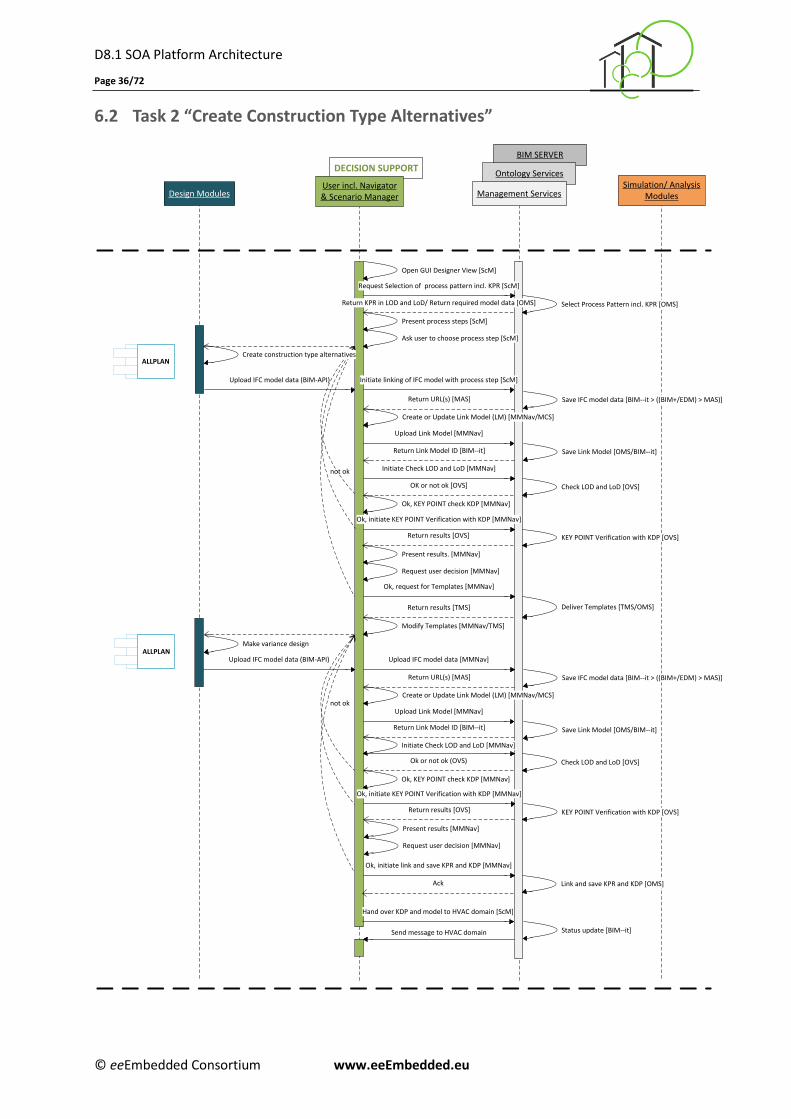
D8.1 SOA Platform Architecture
Page 36/72
© eeEmbedded Consortium www.eeEmbedded.eu
6.2 Task 2 “Create Construction Type Alternatives”
DECISION SUPPORT
BIM SERVER
Ontology Services
Design ModulesSimulation/ Analysis
ModulesUser incl. Navigator& Scenario Manager Management Services
Ok, KEY POINT check KDP [MMNav]
ALLPLAN
Open GUI Designer View [ScM]
Ok, initiate KEY POINT Verification with KDP [MMNav]
Ok, initiate link and save KPR and KDP [MMNav]
Ok, KEY POINT check KDP [MMNav]
not ok
Return KPR in LOD and LoD/ Return required model data [OMS]
KEY POINT Verification with KDP [OVS]
Ok, request for Templates [MMNav]
Return results [TMS] Deliver Templates [TMS/OMS]
Modify Templates [MMNav/TMS]
Select Process Pattern incl. KPR [OMS]
Initiate Check LOD and LoD [MMNav]
OK or not ok [OVS]
Initiate Check LOD and LoD [MMNav]
Check LOD and LoD [OVS]
not ok
Check LOD and LoD [OVS]Ok or not ok (OVS)
Ok, initiate KEY POINT Verification with KDP [MMNav]
KEY POINT Verification with KDP [OVS]
Link and save KPR and KDP [OMS]Ack
Create or Update Link Model (LM) [MMNav/MCS]
Save IFC model data [BIM--it > ((BIM+/EDM) > MAS)]
Return Link Model ID [BIM--it]
Upload IFC model data [MMNav]Upload IFC model data (BIM-API)
Upload IFC model data (BIM-API)
Return results [OVS]
Request user decision [MMNav]
Present results. [MMNav]
Hand over KDP and model to HVAC domain [ScM]
Status update [BIM--it]
Request Selection of process pattern incl. KPR [ScM]
Present process steps [ScM]
Ask user to choose process step [ScM]
Create construction type alternatives
Initiate linking of IFC model with process step [ScM]
Return URL(s) [MAS]
Upload Link Model [MMNav]
Save Link Model [OMS/BIM--it]
Create or Update Link Model (LM) [MMNav/MCS]
Save IFC model data [BIM--it > ((BIM+/EDM) > MAS)]
Return Link Model ID [BIM--it]
Return URL(s) [MAS]
Upload Link Model [MMNav]
Save Link Model [OMS/BIM--it]
Make variance design
Return results [OVS]
Request user decision [MMNav]
Present results [MMNav]
Send message to HVAC domain
ALLPLAN
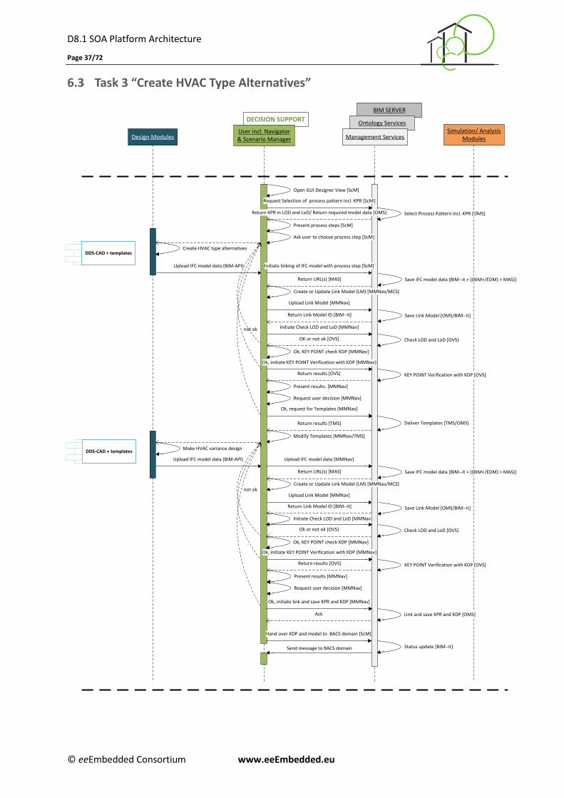
D8.1 SOA Platform Architecture
Page 37/72
© eeEmbedded Consortium www.eeEmbedded.eu
6.3 Task 3 “Create HVAC Type Alternatives”
DECISION SUPPORT
BIM SERVER
Ontology Services
Design ModulesSimulation/ Analysis
Modules
DDS-CAD + templates
DDS-CAD + templates
User incl. Navigator& Scenario Manager Management Services
Ok, KEY POINT check KDP [MMNav]
Open GUI Designer View [ScM]
Ok, initiate KEY POINT Verification with KDP [MMNav]
Ok, initiate link and save KPR and KDP [MMNav]
Ok, KEY POINT check KDP [MMNav]
not ok
Return KPR in LOD and LoD/ Return required model data [OMS]
KEY POINT Verification with KDP [OVS]
Ok, request for Templates [MMNav]
Return results [TMS] Deliver Templates [TMS/OMS]
Modify Templates [MMNav/TMS]
Select Process Pattern incl. KPR [OMS]
Initiate Check LOD and LoD [MMNav]
OK or not ok [OVS]
Initiate Check LOD and LoD [MMNav]
Check LOD and LoD [OVS]
not ok
Check LOD and LoD [OVS]Ok or not ok (OVS)
Ok, initiate KEY POINT Verification with KDP [MMNav]
KEY POINT Verification with KDP [OVS]
Link and save KPR and KDP [OMS]Ack
Create or Update Link Model (LM) [MMNav/MCS]
Save IFC model data [BIM--it > ((BIM+/EDM) > MAS)]
Return Link Model ID [BIM--it]
Upload IFC model data [MMNav]Upload IFC model data (BIM-API)
Upload IFC model data (BIM-API)
Return results [OVS]
Request user decision [MMNav]
Present results. [MMNav]
Hand over KDP and model to BACS domain [ScM]
Status update [BIM--it]
Request Selection of process pattern incl. KPR [ScM]
Present process steps [ScM]
Ask user to choose process step [ScM]
Create HVAC type alternatives
Initiate linking of IFC model with process step [ScM]
Return URL(s) [MAS]
Upload Link Model [MMNav]
Save Link Model [OMS/BIM--it]
Create or Update Link Model (LM) [MMNav/MCS]
Save IFC model data [BIM--it > ((BIM+/EDM) > MAS)]
Return Link Model ID [BIM--it]
Return URL(s) [MAS]
Upload Link Model [MMNav]
Save Link Model [OMS/BIM--it]
Make HVAC variance design
Return results [OVS]
Request user decision [MMNav]
Present results [MMNav]
Send message to BACS domain
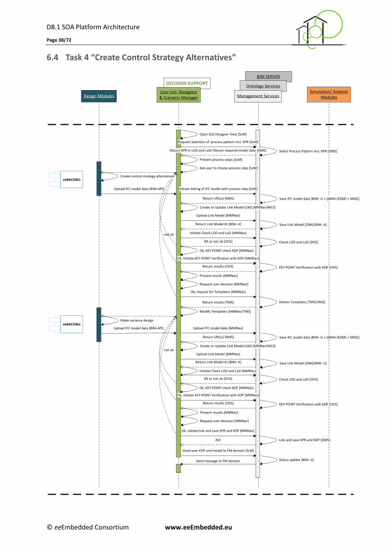
D8.1 SOA Platform Architecture
Page 38/72
© eeEmbedded Consortium www.eeEmbedded.eu
6.4 Task 4 “Create Control Strategy Alternatives”
DECISION SUPPORT
BIM SERVER
Ontology Services
Design ModulesSimulation/ Analysis
ModulesUser incl. Navigator& Scenario Manager Management Services
Ok, KEY POINT check KDP [MMNav]
eeBACSWiz
Open GUI Designer View [ScM]
Ok, initiate KEY POINT Verification with KDP [MMNav]
Ok, initiate link and save KPR and KDP [MMNav]
Ok, KEY POINT check KDP [MMNav]
not ok
KEY POINT Verification with KDP [OVS]
Ok, request for Templates [MMNav]
Return results [TMS] Deliver Templates [TMS/OMS]
Modify Templates [MMNav/TMS]
Select Process Pattern incl. KPR [OMS]
Initiate Check LOD and LoD [MMNav]
OK or not ok [OVS]
Initiate Check LOD and LoD [MMNav]
Check LOD and LoD [OVS]
not ok
Check LOD and LoD [OVS]Ok or not ok (OVS)
KEY POINT Verification with KDP [OVS]
Link and save KPR and KDP [OMS]Ack
Save IFC model data [BIM--it > ((BIM+/EDM) > MAS)]
Return Link Model ID [BIM--it]
Upload IFC model data [MMNav]Upload IFC model data (BIM-API)
Upload IFC model data (BIM-API)
Return results [OVS]
Request user decision [MMNav]
Present results [MMNav]
Request Selection of process pattern incl. KPR [ScM]
Present process steps [ScM]
Ask user to choose process step [ScM]
Create control strategy alternatives
Return URL(s) [MAS]
Upload Link Model [MMNav]
Save Link Model [OMS/BIM--it]
Save IFC model data [BIM--it > ((BIM+/EDM) > MAS)]
Return Link Model ID [BIM--it]
Return URL(s) [MAS]
Upload Link Model [MMNav]
Save Link Model [OMS/BIM--it]
Make variance design
Return results [OVS]
Request user decision [MMNav]
Present results [MMNav]
Hand over KDP and model to FM domain [ScM]
Status update [BIM--it]Send message to FM domain
eeBACSWiz
Return KPR in LOD and LoD/ Return required model data [OMS]
Create or Update Link Model (LM) [MMNav/MCS]
Create or Update Link Model (LM) [MMNav/MCS]
Initiate linking of IFC model with process step [ScM]
Ok, initiate KEY POINT Verification with KDP [MMNav]
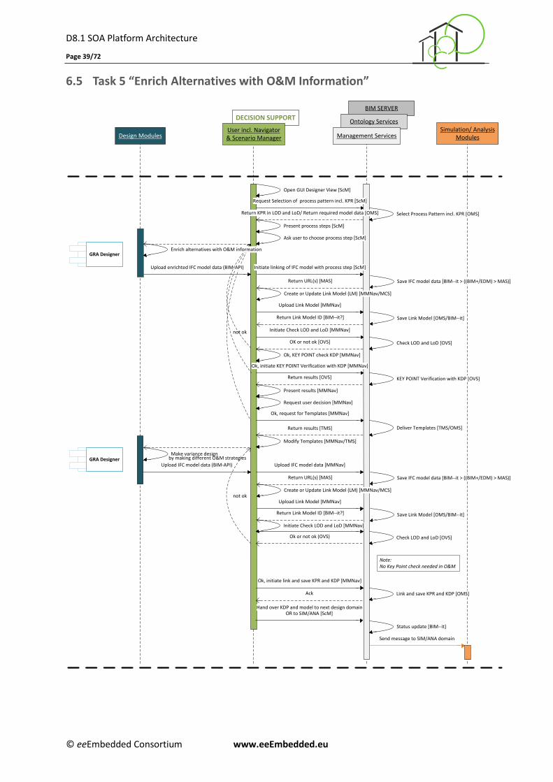
D8.1 SOA Platform Architecture
Page 39/72
© eeEmbedded Consortium www.eeEmbedded.eu
6.5 Task 5 “Enrich Alternatives with O&M Information”
DECISION SUPPORT
BIM SERVER
Ontology Services
Design ModulesSimulation/ Analysis
ModulesUser incl. Navigator& Scenario Manager Management Services
Ok, KEY POINT check KDP [MMNav]
GRA Designer
Open GUI Designer View [ScM]
Ok, initiate KEY POINT Verification with KDP [MMNav]
Ok, initiate link and save KPR and KDP [MMNav]
not ok
Return KPR in LOD and LoD/ Return required model data [OMS]
KEY POINT Verification with KDP [OVS]
Ok, request for Templates [MMNav]
Return results [TMS] Deliver Templates [TMS/OMS]
Modify Templates [MMNav/TMS]
Select Process Pattern incl. KPR [OMS]
Initiate Check LOD and LoD [MMNav]
OK or not ok [OVS]
Initiate Check LOD and LoD [MMNav]
Check LOD and LoD [OVS]
not ok
Check LOD and LoD [OVS]Ok or not ok (OVS)
Link and save KPR and KDP [OMS]Ack
Create or Update Link Model (LM) [MMNav/MCS]
Save IFC model data [BIM--it > ((BIM+/EDM) > MAS)]
Return Link Model ID [BIM--it?]
Upload IFC model data [MMNav]Upload IFC model data (BIM-API)
Upload enrichted IFC model data (BIM-API)
Return results [OVS]
Request user decision [MMNav]
Present results [MMNav]
OR to SIM/ANA [ScM]
Status update [BIM--it]
Request Selection of process pattern incl. KPR [ScM]
Present process steps [ScM]
Ask user to choose process step [ScM]
Enrich alternatives with O&M information
Initiate linking of IFC model with process step [ScM]
Return URL(s) [MAS]
Upload Link Model [MMNav]
Save Link Model [OMS/BIM--it]
Create or Update Link Model (LM) [MMNav/MCS]
Save IFC model data [BIM--it > ((BIM+/EDM) > MAS)]
Return Link Model ID [BIM--it?]
Return URL(s) [MAS]
Upload Link Model [MMNav]
Save Link Model [OMS/BIM--it]
Make variance design
Send message to SIM/ANA domain
Hand over KDP and model to next design domain
GRA Designer
by making different O&M strategies
Note:No Key Point check needed in O&M
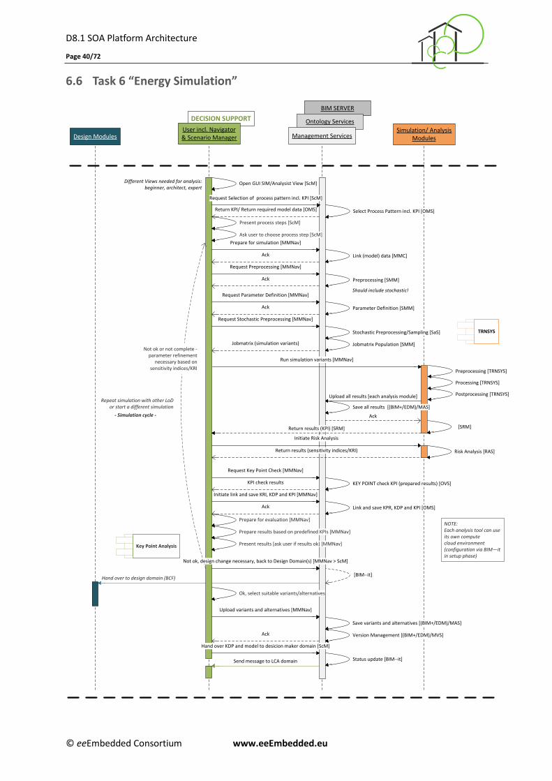
D8.1 SOA Platform Architecture
Page 40/72
© eeEmbedded Consortium www.eeEmbedded.eu
6.6 Task 6 “Energy Simulation”
BIM SERVER
Ontology ServicesDECISION SUPPORT
Management ServicesUser incl. Navigator& Scenario ManagerDesign Modules
Simulation/ AnalysisModules
Prepare for evaluation [MMNav]
TRNSYS
Request Preprocessing [MMNav]
Upload all results [each analysis module]
Open GUI SIM/Analysist View [ScM]
Request Parameter Definition [MMNav]
Preprocessing [SMM]
Parameter Definition [SMM]
Ack
[BIM--it]
Different Views needed for analysis: beginner, architect, expert
Jobmatrix (simulation variants)
Ack
Should include stochastic!
Save all results [(BIM+/EDM)/MAS]
KEY POINT check KPI (prepared results) [OVS]
Request Key Point Check [MMNav]
KPI check results
Link and save KPR, KDP and KPI [OMS]Ack
Hand over to design domain (BCF)
[SRM]
Status update [BIM--it]
Repeat simulation with other LoD or start a different simulation
- Simulation cycle -
Initiate link and save KRI, KDP and KPI [MMNav]
Prepare results based on predefined KPIs [MMNav]
Present results [ask user if results ok) [MMNav]
Ok, select suitable variants/alternatives
Upload variants and alternatives [MMNav]
Hand over KDP and model to desicion maker domain [ScM]
Run simulation variants [MMNav]
Return KPI/ Return required model data [OMS] Select Process Pattern incl. KPI [OMS]
Request Selection of process pattern incl. KPI [ScM]
Ack
Present process steps [ScM]
Ask user to choose process step [ScM]
Link (model) data [MMC]
Prepare for simulation [MMNav]
Ack
Key Point Analysis
NOTE:Each analysis tool can use its own compute cloud environment(configuration via BIM—it in setup phase)
Stochastic Preprocessing/Sampling [SaS]
Jobmatrix Population [SMM]
Ack
Request Stochastic Preprocessing [MMNav]
Risk Analysis [RAS]
Initiate Risk Analysis
Return results (sensitivity indices/KRI)
Return results (KPI) [SRM]
Not ok, design change necessary, back to Design Domain(s) [MMNav > ScM]
Send message to LCA domain
Save variants and alternatives [(BIM+/EDM)/MAS]
Version Management [(BIM+/EDM)/MVS]
Preprocessing [TRNSYS]
Processing [TRNSYS]
Postprocessing [TRNSYS]
Not ok or not complete - parameter refinement
necessary based on sensitivity indices/KRI
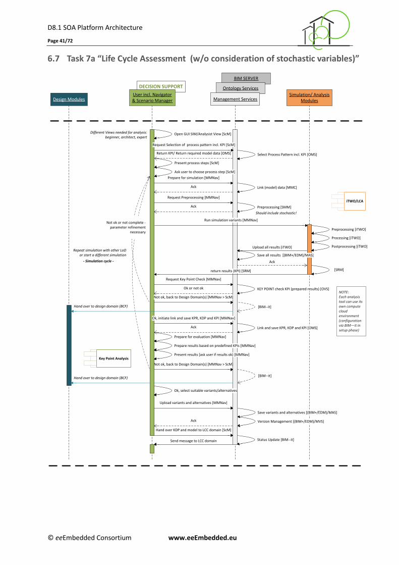
D8.1 SOA Platform Architecture
Page 41/72
© eeEmbedded Consortium www.eeEmbedded.eu
6.7 Task 7a “Life Cycle Assessment (w/o consideration of stochastic variables)”
Design ModulesSimulation/ Analysis
Modules
BIM SERVER
Ontology ServicesDECISION SUPPORT
Management ServicesUser incl. Navigator& Scenario Manager
Prepare for evaluation [MMNav]
iTWO/LCARequest Preprocessing [MMNav]
Upload all results [iTWO]
Open GUI SIM/Analysist View [ScM]
Preprocessing [SMM]
Preprocessing [iTWO]
Processing [iTWO]
Postprocessing [iTWO]
Ack
Not ok, back to Design Domain(s) [MMNav > ScM]
[BIM--it]
Different Views needed for analysis: beginner, architect, expert
Ack
Should include stochastic!
Save all results [(BIM+/EDM)/MAS]
KEY POINT check KPI (prepared results) [OVS]
Request Key Point Check [MMNav]
Ok or not ok
Link and save KPR, KDP and KPI [OMS]Ack
Hand over to design domain (BCF)
[SRM]return results (KPI) [SRM]
Repeat simulation with other LoD or start a different simulation
- Simulation cycle -
Ok, initiate link and save KPR, KDP and KPI [MMNav]
Prepare results based on predefined KPIs [MMNav]
Present results [ask user if results ok) [MMNav]
Ok, select suitable variants/alternatives
Upload variants and alternatives [MMNav]
Run simulation variants [MMNav]
Return KPI/ Return required model data [OMS] Select Process Pattern incl. KPI [OMS]
Request Selection of process pattern incl. KPI [ScM]
Ack
Present process steps [ScM]
Ask user to choose process step [ScM]
Link (model) data [MMC]
Prepare for simulation [MMNav]
Ack
Key Point Analysis
Not ok, back to Design Domain(s) [MMNav > ScM]
[BIM--it]Hand over to design domain (BCF)
Status Update [BIM--it]
Hand over KDP and model to LCC domain [ScM]
Send message to LCC domain
NOTE:Each analysis tool can use its own compute cloud environment(configuration via BIM—it in setup phase)
Save variants and alternatives [(BIM+/EDM)/MAS]
Version Management [(BIM+/EDM)/MVS]
Not ok or not complete - parameter refinement
necessary
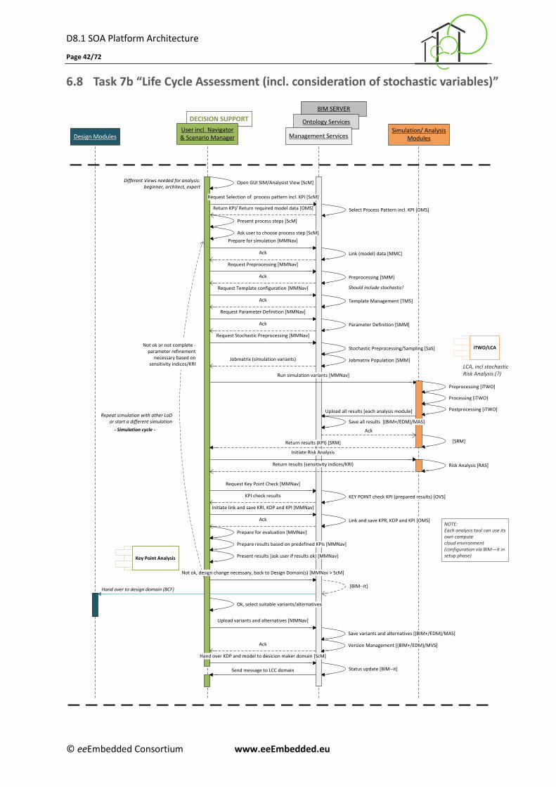
D8.1 SOA Platform Architecture
Page 42/72
© eeEmbedded Consortium www.eeEmbedded.eu
6.8 Task 7b “Life Cycle Assessment (incl. consideration of stochastic variables)”
BIM SERVER
Ontology ServicesDECISION SUPPORT
Management ServicesUser incl. Navigator& Scenario ManagerDesign Modules
Simulation/ AnalysisModules
Template Management [TMS]
Prepare for evaluation [MMNav]
iTWO/LCA
Request Preprocessing [MMNav]
Upload all results [each analysis module]
Open GUI SIM/Analysist View [ScM]
Request Template configuration [MMNav]
Request Parameter Definition [MMNav]
Preprocessing [SMM]
Parameter Definition [SMM]
Ack
[BIM--it]
Different Views needed for analysis: beginner, architect, expert
Ack
Jobmatrix (simulation variants)
Ack
Should include stochastic!
Save all results [(BIM+/EDM)/MAS]
KEY POINT check KPI (prepared results) [OVS]
Request Key Point Check [MMNav]
KPI check results
Link and save KPR, KDP and KPI [OMS]Ack
Hand over to design domain (BCF)
[SRM]
Status update [BIM--it]
Repeat simulation with other LoD or start a different simulation
- Simulation cycle -
Initiate link and save KRI, KDP and KPI [MMNav]
Prepare results based on predefined KPIs [MMNav]
Present results [ask user if results ok) [MMNav]
Ok, select suitable variants/alternatives
Upload variants and alternatives [MMNav]
Hand over KDP and model to desicion maker domain [ScM]
Run simulation variants [MMNav]
Return KPI/ Return required model data [OMS] Select Process Pattern incl. KPI [OMS]
Request Selection of process pattern incl. KPI [ScM]
Ack
Present process steps [ScM]
Ask user to choose process step [ScM]
Link (model) data [MMC]
Prepare for simulation [MMNav]
Ack
Key Point Analysis
NOTE:Each analysis tool can use its own compute cloud environment(configuration via BIM—it in setup phase)
Stochastic Preprocessing/Sampling [SaS]
Jobmatrix Population [SMM]
Ack
Request Stochastic Preprocessing [MMNav]
Risk Analysis [RAS]
Initiate Risk Analysis
Return results (sensitivity indices/KRI)
Return results (KPI) [SRM]
Not ok, design change necessary, back to Design Domain(s) [MMNav > ScM]
Send message to LCC domain
Save variants and alternatives [(BIM+/EDM)/MAS]
Version Management [(BIM+/EDM)/MVS]
Preprocessing [iTWO]
Processing [iTWO]
Postprocessing [iTWO]
LCA, incl stochasticRisk Analysis (?)
Not ok or not complete - parameter refinement
necessary based on sensitivity indices/KRI
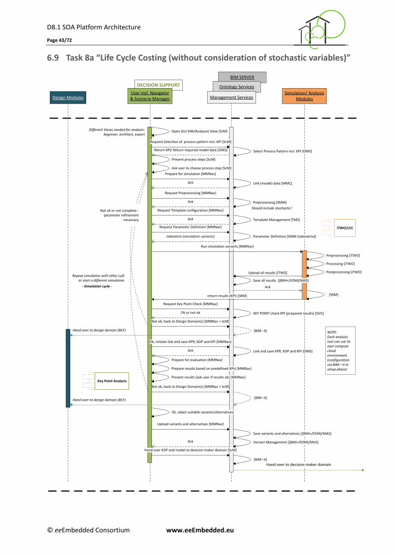
D8.1 SOA Platform Architecture
Page 43/72
© eeEmbedded Consortium www.eeEmbedded.eu
6.9 Task 8a “Life Cycle Costing (without consideration of stochastic variables)”
Design ModulesSimulation/ Analysis
Modules
Different Views needed for analysis: beginner, architect, expert
BIM SERVER
Ontology ServicesDECISION SUPPORT
Management ServicesUser incl. Navigator& Scenario Manager
Template Management [TMS]
Prepare for evaluation [MMNav]
iTWO/LCC
Request Preprocessing [MMNav]
Upload all results [iTWO]
Open GUI SIM/Analysist View [ScM]
Request Template configuration [MMNav]
Request Parameter Definition [MMNav]
Preprocessing [SMM]
Preprocessing [iTWO]
Parameter Definition [SMM (Jobmatrix)]
Processing [iTWO]
Postprocessing [iTWO]
Ack
Not ok, back to Design Domain(s) [MMNav > ScM]
[BIM--it]
Ack
Jobmatrix (simulation variants)
Ack
Should include stochastic!
Save all results [(BIM+/EDM)/MAS]
KEY POINT check KPI (prepared results) [OVS]
Request Key Point Check [MMNav]
Ok or not ok
Link and save KPR, KDP and KPI [OMS]Ack
Hand over to decision maker domain
Hand over to design domain (BCF)
[SRM]
[BIM--it]
return results (KPI) [SRM]
Repeat simulation with other LoD or start a different simulation
- Simulation cycle -
Ok, initiate link and save KPR, KDP and KPI [MMNav]
Prepare results based on predefined KPIs [MMNav]
Present results [ask user if results ok) [MMNav]
Ok, select suitable variants/alternatives
Upload variants and alternatives [MMNav]
Hand over KDP and model to desicion maker domain [ScM]
Run simulation variants [MMNav]
Return KPI/ Return required model data [OMS] Select Process Pattern incl. KPI [OMS]
Request Selection of process pattern incl. KPI [ScM]
Ack
Present process steps [ScM]
Ask user to choose process step [ScM]
Link (model) data [MMC]
Prepare for simulation [MMNav]
Ack
Key Point Analysis
Not ok, back to Design Domain(s) [MMNav > ScM]
[BIM--it]Hand over to design domain (BCF)NOTE:Each analysis tool can use its own compute cloud environment(configuration via BIM—it in setup phase)
Save variants and alternatives [(BIM+/EDM)/MAS]
Version Management [(BIM+/EDM)/MVS]
Not ok or not complete - parameter refinement
necessary
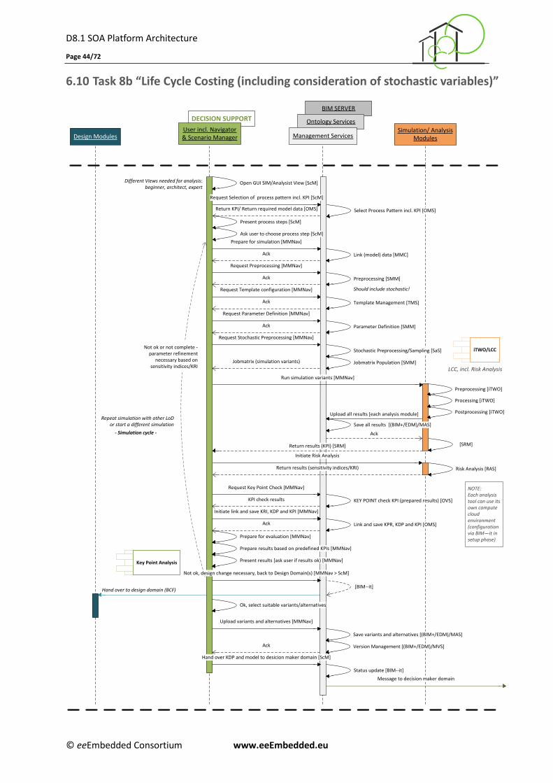
D8.1 SOA Platform Architecture
Page 44/72
© eeEmbedded Consortium www.eeEmbedded.eu
6.10 Task 8b “Life Cycle Costing (including consideration of stochastic variables)”
BIM SERVER
Ontology ServicesDECISION SUPPORT
Management ServicesUser incl. Navigator& Scenario ManagerDesign Modules
Simulation/ AnalysisModules
Template Management [TMS]
Prepare for evaluation [MMNav]
iTWO/LCC
Request Preprocessing [MMNav]
Upload all results [each analysis module]
Open GUI SIM/Analysist View [ScM]
Request Template configuration [MMNav]
Request Parameter Definition [MMNav]
Preprocessing [SMM]
Parameter Definition [SMM]
Ack
[BIM--it]
Different Views needed for analysis: beginner, architect, expert
Ack
Jobmatrix (simulation variants)
Ack
Should include stochastic!
Save all results [(BIM+/EDM)/MAS]
KEY POINT check KPI (prepared results) [OVS]
Request Key Point Check [MMNav]
KPI check results
Link and save KPR, KDP and KPI [OMS]Ack
Message to decision maker domain
Hand over to design domain (BCF)
[SRM]
Status update [BIM--it]
Repeat simulation with other LoD or start a different simulation
- Simulation cycle -
Initiate link and save KRI, KDP and KPI [MMNav]
Prepare results based on predefined KPIs [MMNav]
Present results [ask user if results ok) [MMNav]
Ok, select suitable variants/alternatives
Upload variants and alternatives [MMNav]
Hand over KDP and model to desicion maker domain [ScM]
Run simulation variants [MMNav]
Return KPI/ Return required model data [OMS] Select Process Pattern incl. KPI [OMS]
Request Selection of process pattern incl. KPI [ScM]
Ack
Present process steps [ScM]
Ask user to choose process step [ScM]
Link (model) data [MMC]
Prepare for simulation [MMNav]
Ack
Key Point Analysis
NOTE:Each analysis tool can use its own compute cloud environment(configuration via BIM—it in setup phase)
Stochastic Preprocessing/Sampling [SaS]
Jobmatrix Population [SMM]
Ack
Request Stochastic Preprocessing [MMNav]
Risk Analysis [RAS]
Initiate Risk Analysis
Return results (sensitivity indices/KRI)
Return results (KPI) [SRM]
Not ok, design change necessary, back to Design Domain(s) [MMNav > ScM]
Save variants and alternatives [(BIM+/EDM)/MAS]
Version Management [(BIM+/EDM)/MVS]
Preprocessing [iTWO]
Processing [iTWO]
Postprocessing [iTWO]
LCC, incl. Risk Analysis
Not ok or not complete - parameter refinement
necessary based on sensitivity indices/KRI
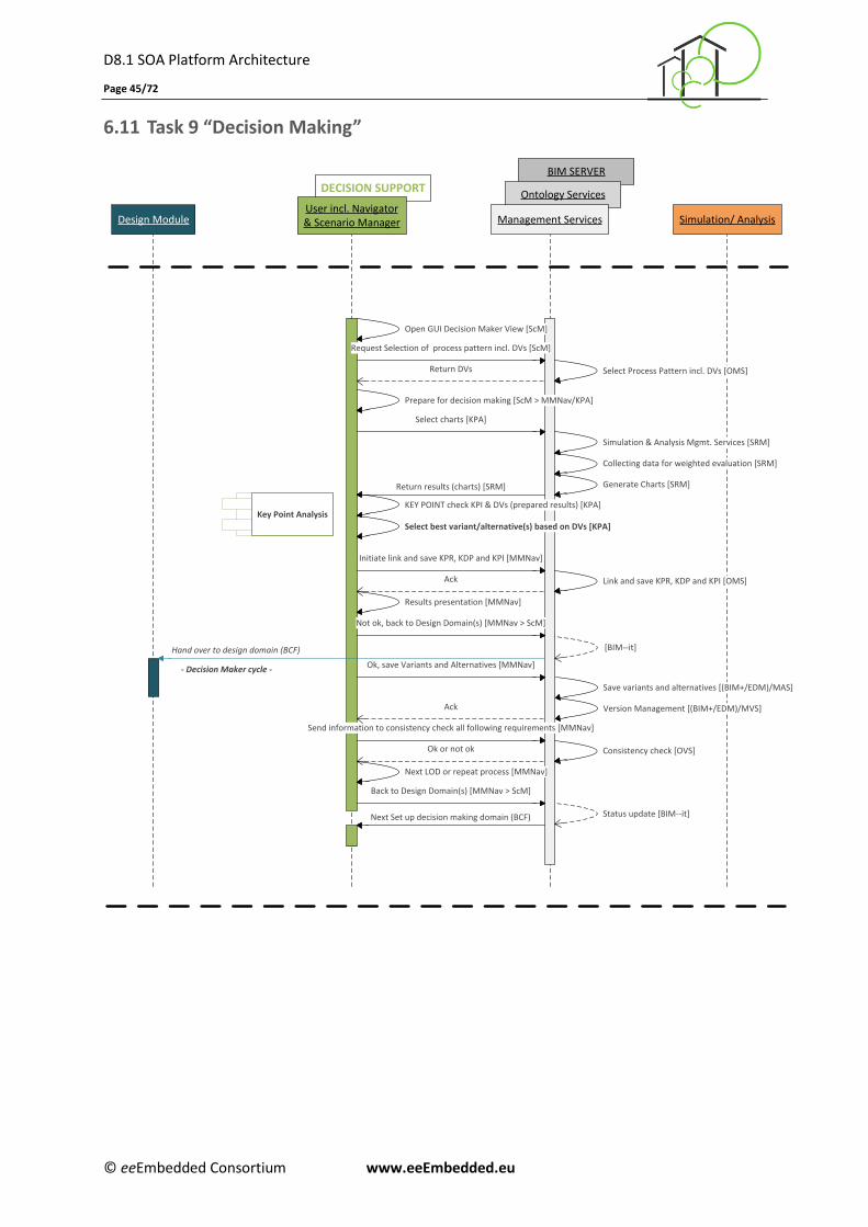
D8.1 SOA Platform Architecture
Page 45/72
© eeEmbedded Consortium www.eeEmbedded.eu
6.11 Task 9 “Decision Making”
DECISION SUPPORT
BIM SERVER
Ontology ServicesUser incl. Navigator& Scenario ManagerDesign Module Management Services Simulation/ Analysis
Key Point Analysis
Select charts [KPA]
Return results (charts) [SRM]
Open GUI Decision Maker View [ScM]
Request Selection of process pattern incl. DVs [ScM]
Return DVs Select Process Pattern incl. DVs [OMS]
Simulation & Analysis Mgmt. Services [SRM]
Collecting data for weighted evaluation [SRM]
Generate Charts [SRM]
Ok, save Variants and Alternatives [MMNav]
Next LOD or repeat process [MMNav]
KEY POINT check KPI & DVs (prepared results) [KPA]
Send information to consistency check all following requirements [MMNav]
Ok or not ok
Not ok, back to Design Domain(s) [MMNav > ScM]
Prepare for decision making [ScM > MMNav/KPA]
Initiate link and save KPR, KDP and KPI [MMNav]
Link and save KPR, KDP and KPI [OMS]Ack
[BIM--it]
Ack
Consistency check [OVS]
Back to Design Domain(s) [MMNav > ScM]
Status update [BIM--it]
Hand over to design domain (BCF)
Results presentation [MMNav]
- Decision Maker cycle -
Select best variant/alternative(s) based on DVs [KPA]
Next Set up decision making domain (BCF)
Save variants and alternatives [(BIM+/EDM)/MAS]
Version Management [(BIM+/EDM)/MVS]
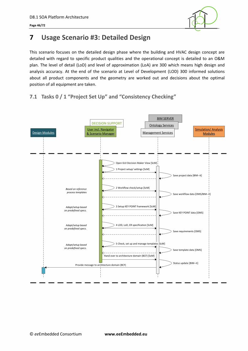
D8.1 SOA Platform Architecture
Page 46/72
© eeEmbedded Consortium www.eeEmbedded.eu
7 Usage Scenario #3: Detailed Design
This scenario focuses on the detailed design phase where the building and HVAC design concept are
detailed with regard to specific product qualities and the operational concept is detailed to an O&M
plan. The level of detail (LoD) and level of approximation (LoA) are 300 which means high design and
analysis accuracy. At the end of the scenario at Level of Development (LOD) 300 informed solutions
about all product components and the geometry are worked out and decisions about the optimal
position of all equipment are taken.
7.1 Tasks 0 / 1 “Project Set Up” and “Consistency Checking”
1 Project setup/ settings [ScM]
Design ModulesSimulation/ Analysis
Modules
3 Setup KEY POINT framework [ScM]
4 LOD, LoD, ER specification [ScM]
Save project data [BIM--it]
Save workflow data [OMS/BIM--it]
Save KEY POINT data [OMS]
Save requirements [OMS]
Save template data [OMS]
Open GUI Decision Maker View [ScM]
Hand over to architecture domain (BCF) [ScM]
Status update [BIM--it]
Based on reference process templates
Adapt/setup based on predefined specs.
Adapt/setup based on predefined specs.
Adapt/setup based on predefined specs.
DECISION SUPPORT
User incl. Navigator& Scenario Manager
BIM SERVER
Ontology Services
Management Services
2 Workflow check/setup [ScM]
Provide message to architecture domain (BCF)
5 Check, set up and manage templates [ScM]

D8.1 SOA Platform Architecture
Page 47/72
© eeEmbedded Consortium www.eeEmbedded.eu
7.2 Task 2 “Create Architectural Product Alternatives”
DECISION SUPPORTBIM SERVER
Ontology Services
Design ModulesSimulation/ Analysis
ModulesUser incl. Navigator& Scenario Manager Management Services
Ok, KEY POINT check KDP [MMNav]
ALLPLAN
Open GUI Designer View [ScM]
Ok, initiate KEY POINT Verification with KDP [MMNav]
Ok, initiate link and save KPR and KDP [MMNav]
Ok, KEY POINT check KDP [MMNav]
not ok
Return KPR in LOD and LoD/ Return required model data [OMS]
KEY POINT Verification with KDP [OVS]
Ok, request for Templates [MMNav]
Return results [TMS] Deliver Templates [TMS/OMS]
Modify Templates [MMNav/TMS]
Select Process Pattern incl. KPR [OMS]
Initiate Check LOD and LoD [MMNav]
OK or not ok [OVS]
Initiate Check LOD and LoD [MMNav]
Check LOD and LoD [OVS]
not ok
Check LOD and LoD [OVS]Ok or not ok (OVS)
Ok, initiate KEY POINT Verification with KDP [MMNav]
KEY POINT Verification with KDP [OVS]
Link and save KPR and KDP [OMS]Ack
Create or Update Link Model (LM) [MMNav/MCS]
Save IFC model data [BIM--it > ((BIM+/EDM) > MAS)]
Return Link Model ID [BIM--it]
Upload IFC model data [MMNav]Upload IFC model data (BIM-API)
Upload IFC model data (BIM-API)
Return results [OVS]
Request user decision [MMNav]
Present results. [MMNav]
Hand over KDP and model to HVAC domain [ScM]
Status update [BIM--it]
Request Selection of process pattern incl. KPR [ScM]
Present process steps [ScM]
Ask user to choose process step [ScM]
Create architecture product alternatives
Initiate linking of IFC model with process step [ScM]
Return URL(s) [MAS]
Upload Link Model [MMNav]
Save Link Model [OMS/BIM--it]
Create or Update Link Model (LM) [MMNav/MCS]
Save IFC model data [BIM--it > ((BIM+/EDM) > MAS)]
Return Link Model ID [BIM--it]
Return URL(s) [MAS]
Upload Link Model [MMNav]
Save Link Model [OMS/BIM--it]
Make variance construction design
Return results [OVS]
Request user decision [MMNav]
Present results [MMNav]
Send message to HVAC domain
ALLPLAN
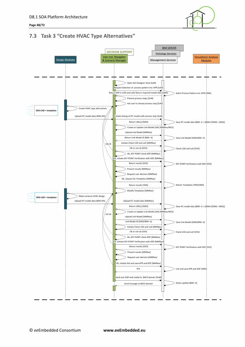
D8.1 SOA Platform Architecture
Page 48/72
© eeEmbedded Consortium www.eeEmbedded.eu
7.3 Task 3 “Create HVAC Type Alternatives”
DECISION SUPPORT
BIM SERVER
Ontology Services
Design ModulesSimulation/ Analysis
Modules
User incl. Navigator& Scenario Manager Management Services
Ok, KEY POINT check KDP [MMNav]
DDS-CAD + templates
Open GUI Designer View [ScM]
Ok, initiate KEY POINT Verification with KDP [MMNav]
Ok, initiate link and save KPR and KDP [MMNav]
Ok, KEY POINT check KDP [MMNav]
not ok
Return KPR in LOD and LoD/ Return required model data [OMS]
KEY POINT Verification with KDP [OVS]
Ok, request for Templates [MMNav]
Return results [TMS] Deliver Templates [TMS/OMS]
Modify Templates [MMNav]
Select Process Pattern incl. KPR [OMS]
Initiate Check LOD and LoD [MMNav]
OK or not ok [OVS]
Initiate Check LOD and LoD [MMNav]
Check LOD and LoD [OVS]
not ok
Check LOD and LoD [OVS]Ok or not ok (OVS)
KEY POINT Verification with KDP [OVS]
Link and save KPR and KDP [OMS]Ack
Create or Update Link Model (LM) [MMNav/MCS]
Save IFC model data [BIM--it > ((BIM+/EDM) > MAS)]
Return Link Model ID [BIM--it]
Upload IFC model data [MMNav]Upload IFC model data (BIM-API)
Upload IFC model data (BIM-API)
Return results [OVS]
Request user decision [MMNav]
Present results [MMNav]
Hand over KDP and model to BACS domain [ScM]
Status update [BIM--it]
Request Selection of process pattern incl. KPR [ScM]
Present process steps [ScM]
Ask user to choose process step [ScM]
Create HVAC type alternatives
Initiate linking of IFC model with process step [ScM]
Return URL(s) [MAS]
Upload Link Model [MMNav]
Save Link Model [OMS/BIM--it]
Save IFC model data [BIM--it > ((BIM+/EDM) > MAS)]
Link Model ID [OMS/BIM--it]
Return URL(s) [MAS]
Upload Link Model [MMNav]
Save Link Model [OMS/BIM--it]
Make variance HVAC design
Return results [OVS]
Request user decision [MMNav]
Present results [MMNav]
DDS-CAD + templates
Send message to BACS domain
Create or Update Link Model (LM) [MMNav/MCS]
Ok, initiate KEY POINT Verification with KDP [MMNav]
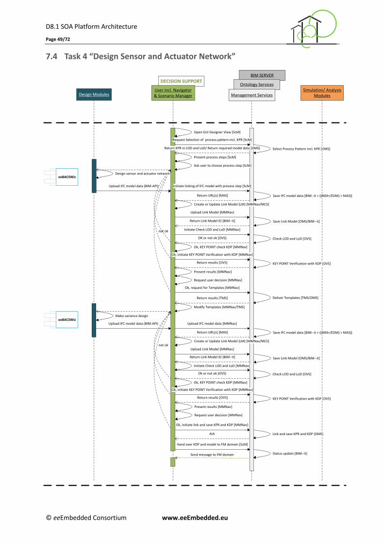
D8.1 SOA Platform Architecture
Page 49/72
© eeEmbedded Consortium www.eeEmbedded.eu
7.4 Task 4 “Design Sensor and Actuator Network”
DECISION SUPPORTBIM SERVER
Ontology Services
Design ModulesSimulation/ Analysis
ModulesUser incl. Navigator& Scenario Manager Management Services
Ok, KEY POINT check KDP [MMNav]
eeBACSWiz
Open GUI Designer View [ScM]
Ok, initiate KEY POINT Verification with KDP [MMNav]
Ok, initiate link and save KPR and KDP [MMNav]
Ok, KEY POINT check KDP [MMNav]
not ok
Return KPR in LOD and LoD/ Return required model data [OMS]
KEY POINT Verification with KDP [OVS]
Ok, request for Templates [MMNav]
Return results [TMS] Deliver Templates [TMS/OMS]
Modify Templates [MMNav/TMS]
Select Process Pattern incl. KPR [OMS]
Initiate Check LOD and LoD [MMNav]
OK or not ok [OVS]
Initiate Check LOD and LoD [MMNav]
Check LOD and LoD [OVS]
not ok
Check LOD and LoD [OVS]Ok or not ok (OVS)
Ok, initiate KEY POINT Verification with KDP [MMNav]
KEY POINT Verification with KDP [OVS]
Link and save KPR and KDP [OMS]Ack
Create or Update Link Model (LM) [MMNav/MCS]
Save IFC model data [BIM--it > ((BIM+/EDM) > MAS)]
Return Link Model ID [BIM--it]
Upload IFC model data [MMNav]Upload IFC model data (BIM-API)
Upload IFC model data (BIM-API)
Return results [OVS]
Request user decision [MMNav]
Present results [MMNav]
Request Selection of process pattern incl. KPR [ScM]
Present process steps [ScM]
Ask user to choose process step [ScM]
Design sensor and actuator network
Initiate linking of IFC model with process step [ScM]
Return URL(s) [MAS]
Upload Link Model [MMNav]
Save Link Model [OMS/BIM--it]
Create or Update Link Model (LM) [MMNav/MCS]
Save IFC model data [BIM--it > ((BIM+/EDM) > MAS)]
Return Link Model ID [BIM--it]
Return URL(s) [MAS]
Upload Link Model [MMNav]
Save Link Model [OMS/BIM--it]
Make variance design
Return results [OVS]
Request user decision [MMNav]
Present results [MMNav]
Hand over KDP and model to FM domain [ScM]
Status update [BIM--it]Send message to FM domain
eeBACSWiz
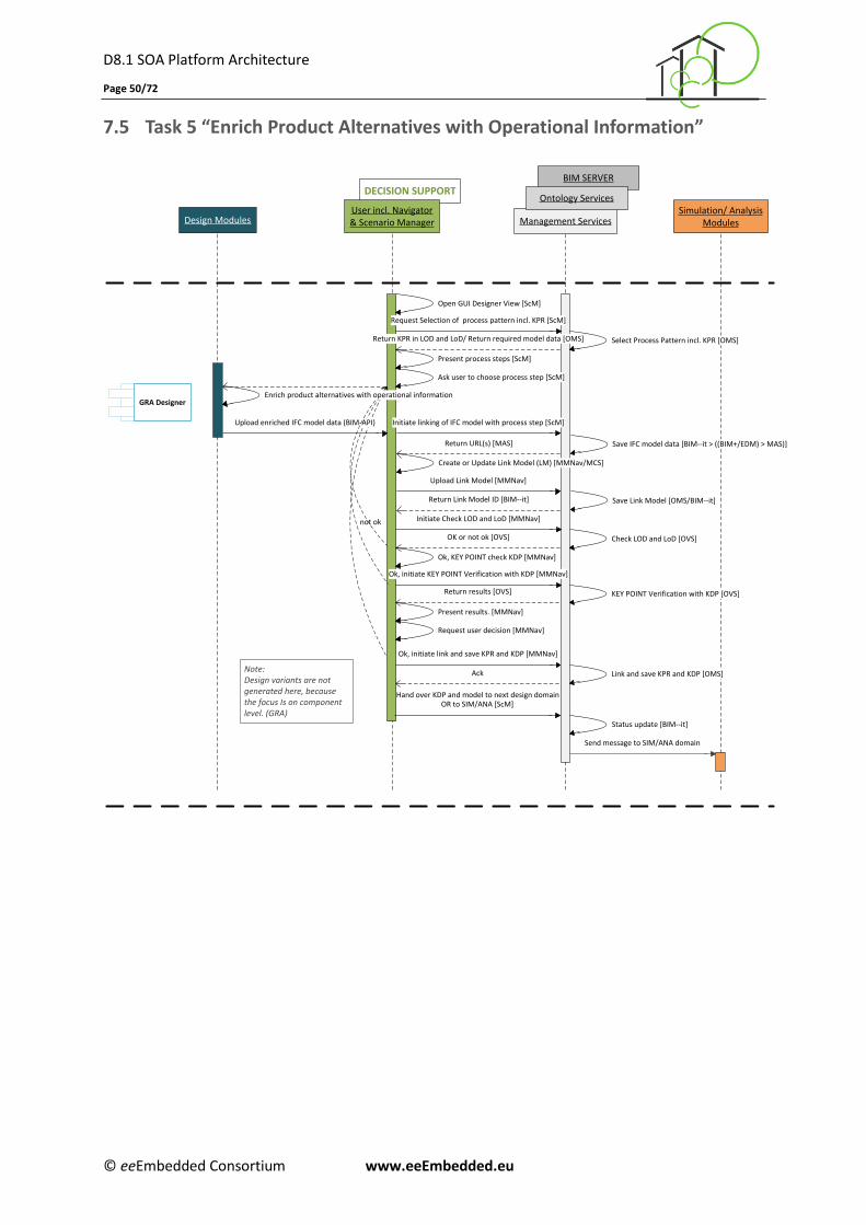
D8.1 SOA Platform Architecture
Page 50/72
© eeEmbedded Consortium www.eeEmbedded.eu
7.5 Task 5 “Enrich Product Alternatives with Operational Information”
Management Services
DECISION SUPPORTBIM SERVER
Ontology Services
Design ModulesSimulation/ Analysis
ModulesUser incl. Navigator& Scenario Manager
Ok, KEY POINT check KDP [MMNav]
Open GUI Designer View [ScM]
Ok, initiate link and save KPR and KDP [MMNav]
Return KPR in LOD and LoD/ Return required model data [OMS]
KEY POINT Verification with KDP [OVS]
Select Process Pattern incl. KPR [OMS]
OK or not ok [OVS]
Initiate Check LOD and LoD [MMNav]
Check LOD and LoD [OVS]
not ok
Link and save KPR and KDP [OMS]Ack
Save IFC model data [BIM--it > ((BIM+/EDM) > MAS)]
Return Link Model ID [BIM--it]
Upload enriched IFC model data (BIM-API)
Return results [OVS]
Request user decision [MMNav]
Present results. [MMNav]
OR to SIM/ANA [ScM]
Status update [BIM--it]
Request Selection of process pattern incl. KPR [ScM]
Present process steps [ScM]
Ask user to choose process step [ScM]
Enrich product alternatives with operational information
Return URL(s) [MAS]
Upload Link Model [MMNav]
Save Link Model [OMS/BIM--it]
Send message to SIM/ANA domain
Hand over KDP and model to next design domain
GRA Designer
Initiate linking of IFC model with process step [ScM]
Create or Update Link Model (LM) [MMNav/MCS]
Ok, initiate KEY POINT Verification with KDP [MMNav]
Note:Design variants are not generated here, because the focus Is on component level. (GRA)
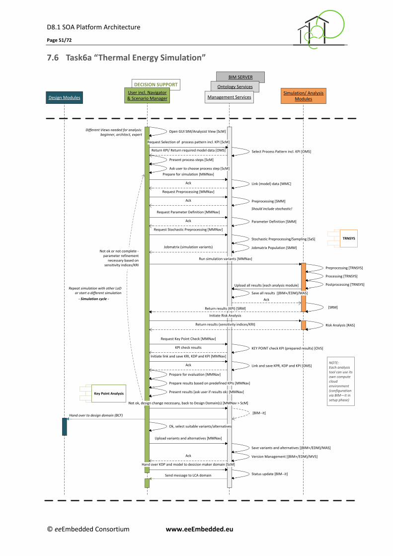
D8.1 SOA Platform Architecture
Page 51/72
© eeEmbedded Consortium www.eeEmbedded.eu
7.6 Task6a “Thermal Energy Simulation”
BIM SERVER
Ontology ServicesDECISION SUPPORT
Management ServicesUser incl. Navigator& Scenario ManagerDesign Modules
Simulation/ AnalysisModules
Prepare for evaluation [MMNav]
TRNSYS
Request Preprocessing [MMNav]
Upload all results [each analysis module]
Open GUI SIM/Analysist View [ScM]
Request Parameter Definition [MMNav]
Preprocessing [SMM]
Preprocessing [TRNSYS]
Parameter Definition [SMM]
Processing [TRNSYS]
Postprocessing [TRNSYS]
Ack
[BIM--it]
Different Views needed for analysis: beginner, architect, expert
Jobmatrix (simulation variants)
Ack
Should include stochastic!
Save all results [(BIM+/EDM)/MAS]
KEY POINT check KPI (prepared results) [OVS]
Request Key Point Check [MMNav]
KPI check results
Link and save KPR, KDP and KPI [OMS]Ack
Hand over to design domain (BCF)
[SRM]
Status update [BIM--it]
Repeat simulation with other LoD or start a different simulation
- Simulation cycle -
Initiate link and save KRI, KDP and KPI [MMNav]
Prepare results based on predefined KPIs [MMNav]
Present results [ask user if results ok) [MMNav]
Ok, select suitable variants/alternatives
Upload variants and alternatives [MMNav]
Hand over KDP and model to desicion maker domain [ScM]
Run simulation variants [MMNav]
Return KPI/ Return required model data [OMS] Select Process Pattern incl. KPI [OMS]
Request Selection of process pattern incl. KPI [ScM]
Ack
Present process steps [ScM]
Ask user to choose process step [ScM]
Link (model) data [MMC]
Prepare for simulation [MMNav]
Ack
Key Point Analysis
NOTE:Each analysis tool can use its own compute cloud environment(configuration via BIM—it in setup phase)
Stochastic Preprocessing/Sampling [SaS]
Jobmatrix Population [SMM]
Ack
Request Stochastic Preprocessing [MMNav]
Risk Analysis [RAS]
Initiate Risk Analysis
Return results (sensitivity indices/KRI)
Return results (KPI) [SRM]
Not ok, design change necessary, back to Design Domain(s) [MMNav > ScM]
Send message to LCA domain
Save variants and alternatives [(BIM+/EDM)/MAS]
Version Management [(BIM+/EDM)/MVS]
Not ok or not complete - parameter refinement
necessary based on sensitivity indices/KRI
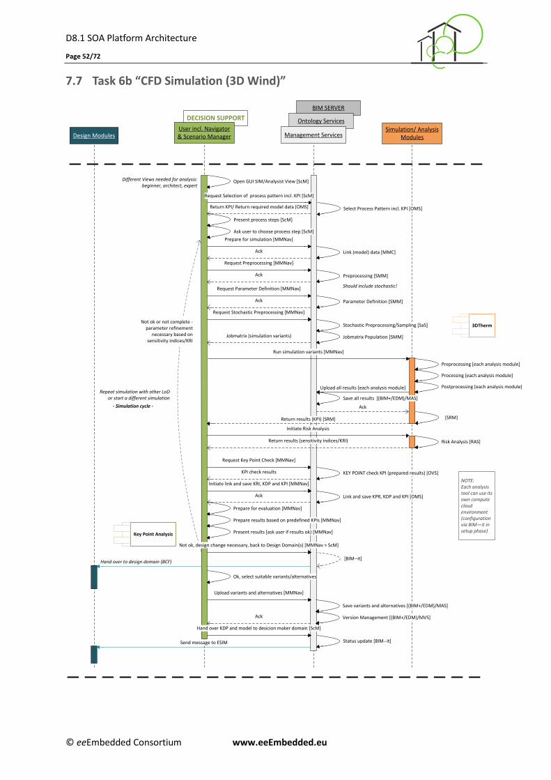
D8.1 SOA Platform Architecture
Page 52/72
© eeEmbedded Consortium www.eeEmbedded.eu
7.7 Task 6b “CFD Simulation (3D Wind)”
BIM SERVER
Ontology ServicesDECISION SUPPORT
Management ServicesUser incl. Navigator& Scenario ManagerDesign Modules
Simulation/ AnalysisModules
Prepare for evaluation [MMNav]
Request Preprocessing [MMNav]
Upload all results [each analysis module]
Open GUI SIM/Analysist View [ScM]
Request Parameter Definition [MMNav]
Preprocessing [SMM]
Preprocessing [each analysis module]
Parameter Definition [SMM]
Processing [each analysis module]
Postprocessing [each analysis module]
Ack
[BIM--it]
Different Views needed for analysis: beginner, architect, expert
Jobmatrix (simulation variants)
Ack
Should include stochastic!
Save all results [(BIM+/EDM)/MAS]
KEY POINT check KPI (prepared results) [OVS]
Request Key Point Check [MMNav]
KPI check results
Link and save KPR, KDP and KPI [OMS]Ack
Hand over to design domain (BCF)
[SRM]
Status update [BIM--it]
Repeat simulation with other LoD or start a different simulation
- Simulation cycle -
Initiate link and save KRI, KDP and KPI [MMNav]
Prepare results based on predefined KPIs [MMNav]
Present results [ask user if results ok) [MMNav]
Ok, select suitable variants/alternatives
Upload variants and alternatives [MMNav]
Hand over KDP and model to desicion maker domain [ScM]
Run simulation variants [MMNav]
Return KPI/ Return required model data [OMS] Select Process Pattern incl. KPI [OMS]
Request Selection of process pattern incl. KPI [ScM]
Ack
Present process steps [ScM]
Ask user to choose process step [ScM]
Link (model) data [MMC]
Prepare for simulation [MMNav]
Ack
Key Point Analysis
NOTE:Each analysis tool can use its own compute cloud environment(configuration via BIM—it in setup phase)
Stochastic Preprocessing/Sampling [SaS]
Jobmatrix Population [SMM]
Ack
Request Stochastic Preprocessing [MMNav]
Risk Analysis [RAS]
Initiate Risk Analysis
Return results (sensitivity indices/KRI)
Return results (KPI) [SRM]
Not ok, design change necessary, back to Design Domain(s) [MMNav > ScM]
Send message to ESIM
Save variants and alternatives [(BIM+/EDM)/MAS]
Version Management [(BIM+/EDM)/MVS]
3DThermNot ok or not complete -
parameter refinement necessary based on
sensitivity indices/KRI
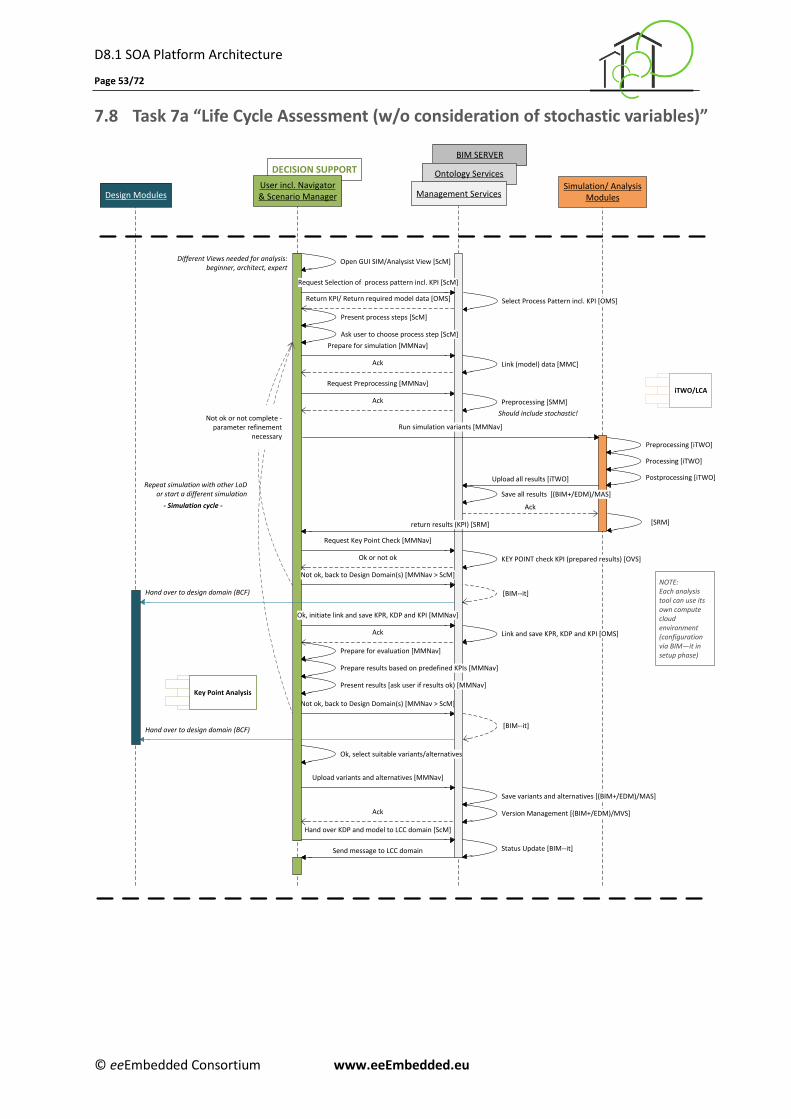
D8.1 SOA Platform Architecture
Page 53/72
© eeEmbedded Consortium www.eeEmbedded.eu
7.8 Task 7a “Life Cycle Assessment (w/o consideration of stochastic variables)”
Design ModulesSimulation/ Analysis
Modules
Different Views needed for analysis: beginner, architect, expert
BIM SERVER
Ontology ServicesDECISION SUPPORT
Management ServicesUser incl. Navigator& Scenario Manager
Prepare for evaluation [MMNav]
iTWO/LCARequest Preprocessing [MMNav]
Upload all results [iTWO]
Open GUI SIM/Analysist View [ScM]
Preprocessing [SMM]
Preprocessing [iTWO]
Processing [iTWO]
Postprocessing [iTWO]
Ack
Not ok, back to Design Domain(s) [MMNav > ScM]
[BIM--it]
Ack
Should include stochastic!
Save all results [(BIM+/EDM)/MAS]
KEY POINT check KPI (prepared results) [OVS]
Request Key Point Check [MMNav]
Ok or not ok
Link and save KPR, KDP and KPI [OMS]Ack
Hand over to design domain (BCF)
[SRM]return results (KPI) [SRM]
Repeat simulation with other LoD or start a different simulation
- Simulation cycle -
Ok, initiate link and save KPR, KDP and KPI [MMNav]
Prepare results based on predefined KPIs [MMNav]
Present results [ask user if results ok) [MMNav]
Ok, select suitable variants/alternatives
Upload variants and alternatives [MMNav]
Run simulation variants [MMNav]
Return KPI/ Return required model data [OMS] Select Process Pattern incl. KPI [OMS]
Request Selection of process pattern incl. KPI [ScM]
Ack
Present process steps [ScM]
Ask user to choose process step [ScM]
Link (model) data [MMC]
Prepare for simulation [MMNav]
Ack
Key Point Analysis
Not ok, back to Design Domain(s) [MMNav > ScM]
[BIM--it]Hand over to design domain (BCF)
Status Update [BIM--it]
Hand over KDP and model to LCC domain [ScM]
Send message to LCC domain
NOTE:Each analysis tool can use its own compute cloud environment(configuration via BIM—it in setup phase)
Save variants and alternatives [(BIM+/EDM)/MAS]
Version Management [(BIM+/EDM)/MVS]
Not ok or not complete - parameter refinement
necessary
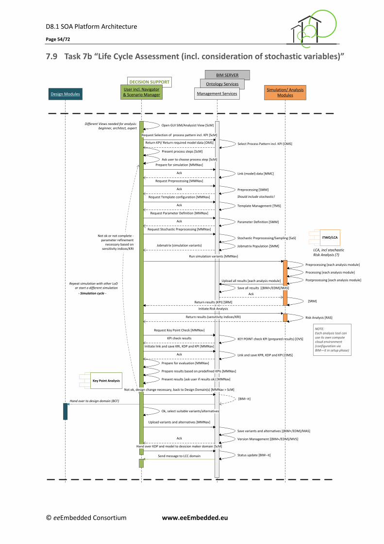
D8.1 SOA Platform Architecture
Page 54/72
© eeEmbedded Consortium www.eeEmbedded.eu
7.9 Task 7b “Life Cycle Assessment (incl. consideration of stochastic variables)”
BIM SERVER
Ontology ServicesDECISION SUPPORT
Management ServicesUser incl. Navigator& Scenario ManagerDesign Modules
Simulation/ AnalysisModules
Template Management [TMS]
Prepare for evaluation [MMNav]
iTWO/LCA
Request Preprocessing [MMNav]
Upload all results [each analysis module]
Open GUI SIM/Analysist View [ScM]
Request Template configuration [MMNav]
Request Parameter Definition [MMNav]
Preprocessing [SMM]
Preprocessing [each analysis module]
Parameter Definition [SMM]
Processing [each analysis module]
Postprocessing [each analysis module]
Ack
[BIM--it]
Different Views needed for analysis: beginner, architect, expert
Ack
Jobmatrix (simulation variants)
Ack
Should include stochastic!
Save all results [(BIM+/EDM)/MAS]
KEY POINT check KPI (prepared results) [OVS]
Request Key Point Check [MMNav]
KPI check results
Link and save KPR, KDP and KPI [OMS]Ack
Hand over to design domain (BCF)
[SRM]
Status update [BIM--it]
Repeat simulation with other LoD or start a different simulation
- Simulation cycle -
Initiate link and save KRI, KDP and KPI [MMNav]
Prepare results based on predefined KPIs [MMNav]
Present results [ask user if results ok) [MMNav]
Ok, select suitable variants/alternatives
Upload variants and alternatives [MMNav]
Hand over KDP and model to desicion maker domain [ScM]
Run simulation variants [MMNav]
Return KPI/ Return required model data [OMS] Select Process Pattern incl. KPI [OMS]
Request Selection of process pattern incl. KPI [ScM]
Ack
Present process steps [ScM]
Ask user to choose process step [ScM]
Link (model) data [MMC]
Prepare for simulation [MMNav]
Ack
Key Point Analysis
NOTE:Each analysis tool can use its own compute cloud environment(configuration via BIM—it in setup phase)
Stochastic Preprocessing/Sampling [SaS]
Jobmatrix Population [SMM]
Ack
Request Stochastic Preprocessing [MMNav]
Risk Analysis [RAS]
Initiate Risk Analysis
Return results (sensitivity indices/KRI)
Return results (KPI) [SRM]
Not ok, design change necessary, back to Design Domain(s) [MMNav > ScM]
Send message to LCC domain
Save variants and alternatives [(BIM+/EDM)/MAS]
Version Management [(BIM+/EDM)/MVS]
LCA, incl stochasticRisk Analysis (?)
Not ok or not complete - parameter refinement
necessary based on sensitivity indices/KRI
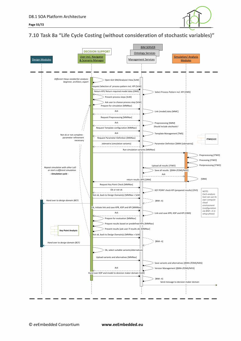
D8.1 SOA Platform Architecture
Page 55/72
© eeEmbedded Consortium www.eeEmbedded.eu
7.10 Task 8a “Life Cycle Costing (without consideration of stochastic variables)”
Design ModulesSimulation/ Analysis
Modules
Different Views needed for analysis: beginner, architect, expert
BIM SERVER
Ontology ServicesDECISION SUPPORT
Management ServicesUser incl. Navigator& Scenario Manager
Template Management [TMS]
Prepare for evaluation [MMNav]
iTWO/LCC
Request Preprocessing [MMNav]
Upload all results [iTWO]
Open GUI SIM/Analysist View [ScM]
Request Template configuration [MMNav]
Request Parameter Definition [MMNav]
Preprocessing [SMM]
Preprocessing [iTWO]
Parameter Definition [SMM (Jobmatrix)]
Processing [iTWO]
Postprocessing [iTWO]
Ack
Not ok, back to Design Domain(s) [MMNav > ScM]
[BIM--it]
Ack
Jobmatrix (simulation variants)
Ack
Should include stochastic!
Save all results [(BIM+/EDM)/MAS]
KEY POINT check KPI (prepared results) [OVS]
Request Key Point Check [MMNav]
Ok or not ok
Link and save KPR, KDP and KPI [OMS]Ack
Send message to decision maker domain
Hand over to design domain (BCF)
[SRM]
[BIM--it]
return results (KPI) [SRM]
Repeat simulation with other LoD or start a different simulation
- Simulation cycle -
Ok, initiate link and save KPR, KDP and KPI [MMNav]
Prepare results based on predefined KPIs [MMNav]
Present results [ask user if results ok) [MMNav]
Ok, select suitable variants/alternatives
Upload variants and alternatives [MMNav]
Hand over KDP and model to desicion maker domain [ScM]
Run simulation variants [MMNav]
Return KPI/ Return required model data [OMS] Select Process Pattern incl. KPI [OMS]
Request Selection of process pattern incl. KPI [ScM]
Ack
Present process steps [ScM]
Ask user to choose process step [ScM]
Link (model) data [MMC]
Prepare for simulation [MMNav]
Ack
Key Point Analysis
Not ok, back to Design Domain(s) [MMNav > ScM]
[BIM--it]Hand over to design domain (BCF)
NOTE:Each analysis tool can use its own compute cloud environment(configuration via BIM—it in setup phase)
Save variants and alternatives [(BIM+/EDM)/MAS]
Version Management [(BIM+/EDM)/MVS]
Not ok or not complete - parameter refinement
necessary
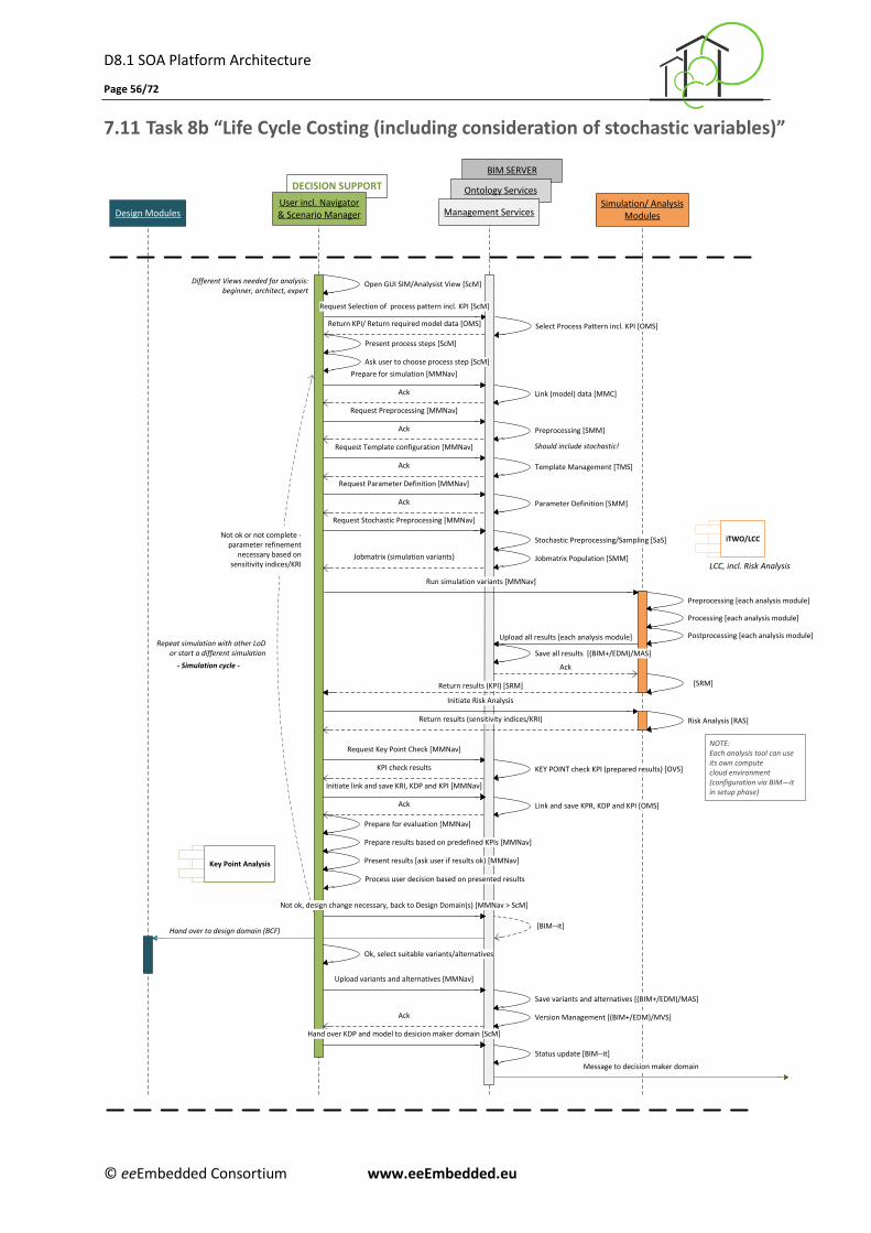
D8.1 SOA Platform Architecture
Page 56/72
© eeEmbedded Consortium www.eeEmbedded.eu
7.11 Task 8b “Life Cycle Costing (including consideration of stochastic variables)”
BIM SERVER
Ontology ServicesDECISION SUPPORT
Management ServicesUser incl. Navigator& Scenario ManagerDesign Modules
Simulation/ AnalysisModules
Template Management [TMS]
Prepare for evaluation [MMNav]
iTWO/LCC
Request Preprocessing [MMNav]
Upload all results [each analysis module]
Open GUI SIM/Analysist View [ScM]
Request Template configuration [MMNav]
Request Parameter Definition [MMNav]
Preprocessing [SMM]
Preprocessing [each analysis module]
Parameter Definition [SMM]
Processing [each analysis module]
Postprocessing [each analysis module]
Ack
[BIM--it]
Different Views needed for analysis: beginner, architect, expert
Ack
Jobmatrix (simulation variants)
Ack
Should include stochastic!
Save all results [(BIM+/EDM)/MAS]
KEY POINT check KPI (prepared results) [OVS]
Request Key Point Check [MMNav]
KPI check results
Link and save KPR, KDP and KPI [OMS]Ack
Message to decision maker domain
Hand over to design domain (BCF)
[SRM]
Status update [BIM--it]
Repeat simulation with other LoD or start a different simulation
- Simulation cycle -
Initiate link and save KRI, KDP and KPI [MMNav]
Prepare results based on predefined KPIs [MMNav]
Present results [ask user if results ok) [MMNav]
Ok, select suitable variants/alternatives
Upload variants and alternatives [MMNav]
Hand over KDP and model to desicion maker domain [ScM]
Run simulation variants [MMNav]
Return KPI/ Return required model data [OMS] Select Process Pattern incl. KPI [OMS]
Request Selection of process pattern incl. KPI [ScM]
Ack
Present process steps [ScM]
Ask user to choose process step [ScM]
Link (model) data [MMC]
Prepare for simulation [MMNav]
Ack
Key Point Analysis
NOTE:Each analysis tool can use its own compute cloud environment(configuration via BIM—it in setup phase)
Stochastic Preprocessing/Sampling [SaS]
Jobmatrix Population [SMM]
Ack
Request Stochastic Preprocessing [MMNav]
Risk Analysis [RAS]
Initiate Risk Analysis
Return results (sensitivity indices/KRI)
Return results (KPI) [SRM]
Process user decision based on presented results
Not ok, design change necessary, back to Design Domain(s) [MMNav > ScM]
Save variants and alternatives [(BIM+/EDM)/MAS]
Version Management [(BIM+/EDM)/MVS]
LCC, incl. Risk Analysis
Not ok or not complete - parameter refinement
necessary based on sensitivity indices/KRI
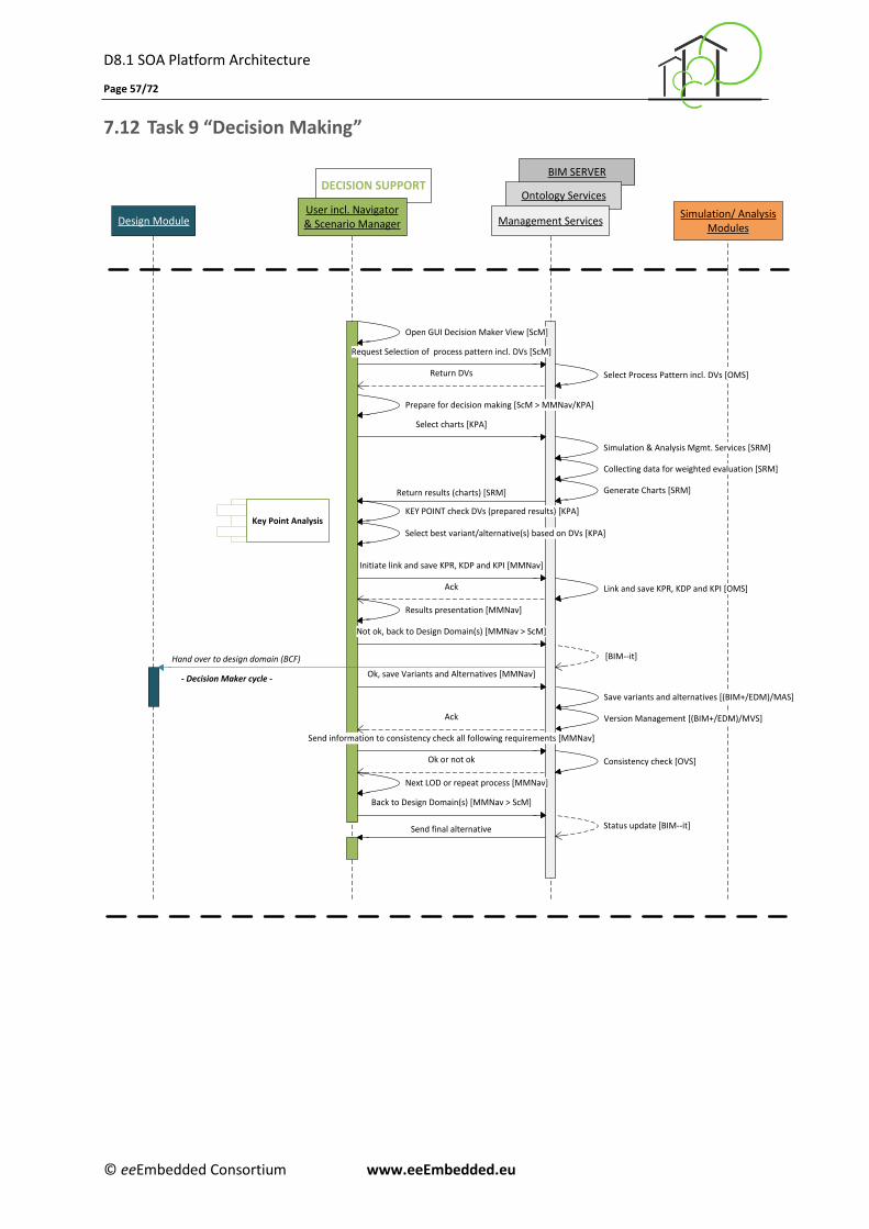
D8.1 SOA Platform Architecture
Page 57/72
© eeEmbedded Consortium www.eeEmbedded.eu
7.12 Task 9 “Decision Making”
DECISION SUPPORTBIM SERVER
Ontology ServicesUser incl. Navigator& Scenario ManagerDesign Module Management Services
Simulation/ AnalysisModules
Key Point Analysis
Select charts [KPA]
Return results (charts) [SRM]
Open GUI Decision Maker View [ScM]
Request Selection of process pattern incl. DVs [ScM]
Return DVs Select Process Pattern incl. DVs [OMS]
Simulation & Analysis Mgmt. Services [SRM]
Collecting data for weighted evaluation [SRM]
Generate Charts [SRM]
Ok, save Variants and Alternatives [MMNav]
Next LOD or repeat process [MMNav]
KEY POINT check DVs (prepared results) [KPA]
Send information to consistency check all following requirements [MMNav]
Ok or not ok
Not ok, back to Design Domain(s) [MMNav > ScM]
Prepare for decision making [ScM > MMNav/KPA]
Initiate link and save KPR, KDP and KPI [MMNav]
Link and save KPR, KDP and KPI [OMS]Ack
[BIM--it]
Ack
Consistency check [OVS]
Back to Design Domain(s) [MMNav > ScM]
Status update [BIM--it]
Hand over to design domain (BCF)
Results presentation [MMNav]
- Decision Maker cycle -
Select best variant/alternative(s) based on DVs [KPA]
Send final alternative
Save variants and alternatives [(BIM+/EDM)/MAS]
Version Management [(BIM+/EDM)/MVS]
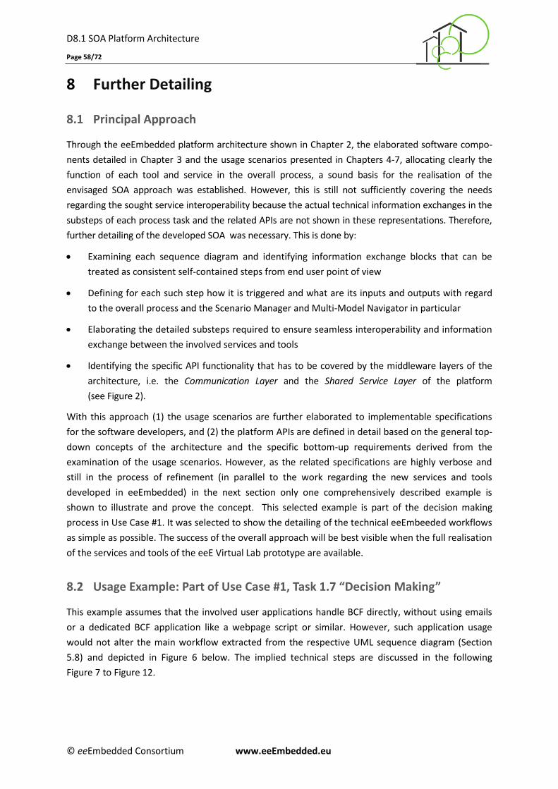
D8.1 SOA Platform Architecture
Page 58/72
© eeEmbedded Consortium www.eeEmbedded.eu
8 Further Detailing
8.1 Principal Approach
Through the eeEmbedded platform architecture shown in Chapter 2, the elaborated software compo-
nents detailed in Chapter 3 and the usage scenarios presented in Chapters 4-7, allocating clearly the
function of each tool and service in the overall process, a sound basis for the realisation of the
envisaged SOA approach was established. However, this is still not sufficiently covering the needs
regarding the sought service interoperability because the actual technical information exchanges in the
substeps of each process task and the related APIs are not shown in these representations. Therefore,
further detailing of the developed SOA was necessary. This is done by:
Examining each sequence diagram and identifying information exchange blocks that can be
treated as consistent self-contained steps from end user point of view
Defining for each such step how it is triggered and what are its inputs and outputs with regard
to the overall process and the Scenario Manager and Multi-Model Navigator in particular
Elaborating the detailed substeps required to ensure seamless interoperability and information
exchange between the involved services and tools
Identifying the specific API functionality that has to be covered by the middleware layers of the
architecture, i.e. the Communication Layer and the Shared Service Layer of the platform
(see Figure 2).
With this approach (1) the usage scenarios are further elaborated to implementable specifications
for the software developers, and (2) the platform APIs are defined in detail based on the general top-
down concepts of the architecture and the specific bottom-up requirements derived from the
examination of the usage scenarios. However, as the related specifications are highly verbose and
still in the process of refinement (in parallel to the work regarding the new services and tools
developed in eeEmbedded) in the next section only one comprehensively described example is
shown to illustrate and prove the concept. This selected example is part of the decision making
process in Use Case #1. It was selected to show the detailing of the technical eeEmbeeded workflows
as simple as possible. The success of the overall approach will be best visible when the full realisation
of the services and tools of the eeE Virtual Lab prototype are available.
8.2 Usage Example: Part of Use Case #1, Task 1.7 “Decision Making”
This example assumes that the involved user applications handle BCF directly, without using emails
or a dedicated BCF application like a webpage script or similar. However, such application usage
would not alter the main workflow extracted from the respective UML sequence diagram (Section
5.8) and depicted in Figure 6 below. The implied technical steps are discussed in the following
Figure 7 to Figure 12.
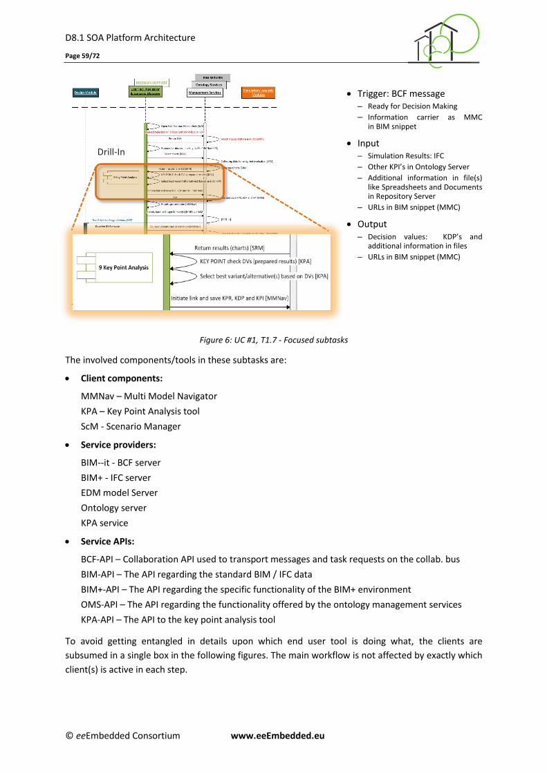
D8.1 SOA Platform Architecture
Page 59/72
© eeEmbedded Consortium www.eeEmbedded.eu
Trigger: BCF message – Ready for Decision Making
– Information carrier as MMC in BIM snippet
Input – Simulation Results: IFC
– Other KPI’s in Ontology Server
– Additional information in file(s) like Spreadsheets and Documents in Repository Server
– URLs in BIM snippet (MMC)
Output – Decision values: KDP’s and
additional information in files
– URLs in BIM snippet (MMC)
Figure 6: UC #1, T1.7 - Focused subtasks
The involved components/tools in these subtasks are:
Client components:
MMNav – Multi Model Navigator
KPA – Key Point Analysis tool
ScM - Scenario Manager
Service providers:
BIM--it - BCF server
BIM+ - IFC server
EDM model Server
Ontology server
KPA service
Service APIs:
BCF-API – Collaboration API used to transport messages and task requests on the collab. bus
BIM-API – The API regarding the standard BIM / IFC data
BIM+-API – The API regarding the specific functionality of the BIM+ environment
OMS-API – The API regarding the functionality offered by the ontology management services
KPA-API – The API to the key point analysis tool
To avoid getting entangled in details upon which end user tool is doing what, the clients are
subsumed in a single box in the following figures. The main workflow is not affected by exactly which
client(s) is active in each step.
Drill-In
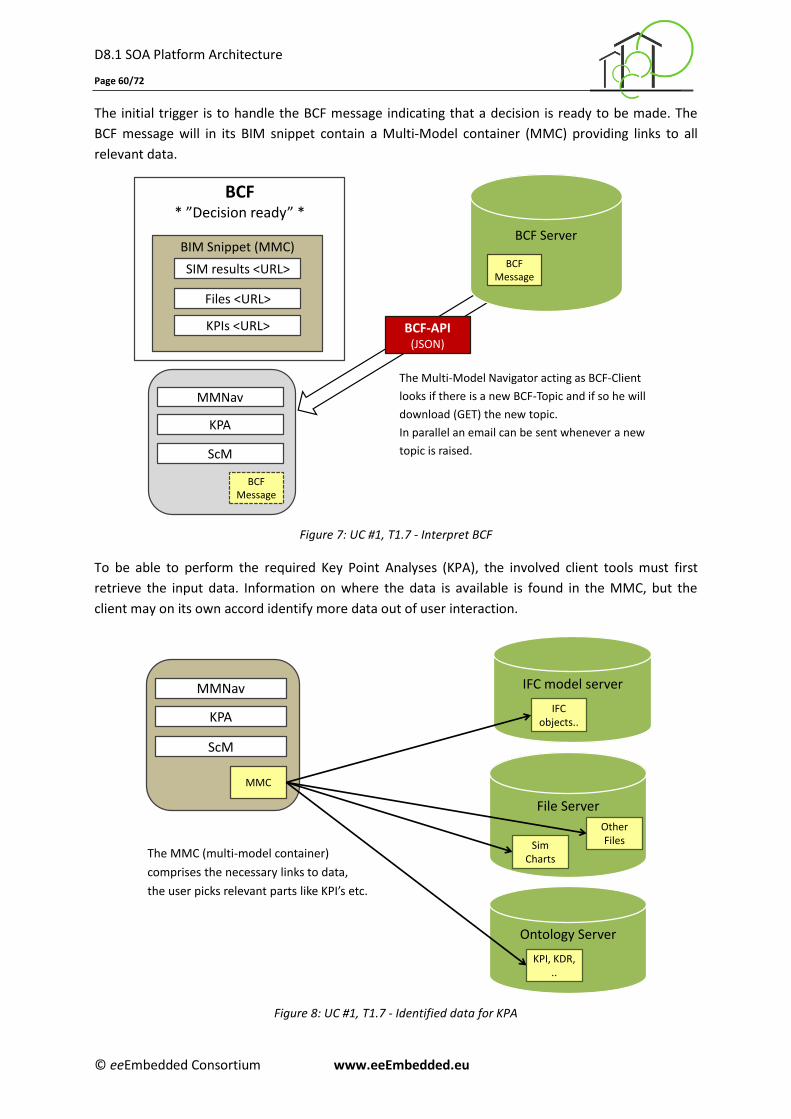
D8.1 SOA Platform Architecture
Page 60/72
© eeEmbedded Consortium www.eeEmbedded.eu
The initial trigger is to handle the BCF message indicating that a decision is ready to be made. The
BCF message will in its BIM snippet contain a Multi-Model container (MMC) providing links to all
relevant data.
Figure 7: UC #1, T1.7 - Interpret BCF
To be able to perform the required Key Point Analyses (KPA), the involved client tools must first
retrieve the input data. Information on where the data is available is found in the MMC, but the
client may on its own accord identify more data out of user interaction.
Figure 8: UC #1, T1.7 - Identified data for KPA
The Multi-Model Navigator acting as BCF-Client
looks if there is a new BCF-Topic and if so he will
download (GET) the new topic.
In parallel an email can be sent whenever a new
topic is raised.
BCF Server
BCF-API(JSON)
BCF Message
BCF* ”Decision ready” *
BIM Snippet (MMC)
KPIs <URL>
SIM results <URL>
Files <URL>
BCF Message
MMNav
KPA
ScM
The MMC (multi-model container)
comprises the necessary links to data,
the user picks relevant parts like KPI’s etc.
File Server
Sim Charts
Other Files
Ontology Server
KPI, KDR, ..
MMC
MMNav
KPA
ScM
IFC model server
IFC objects..
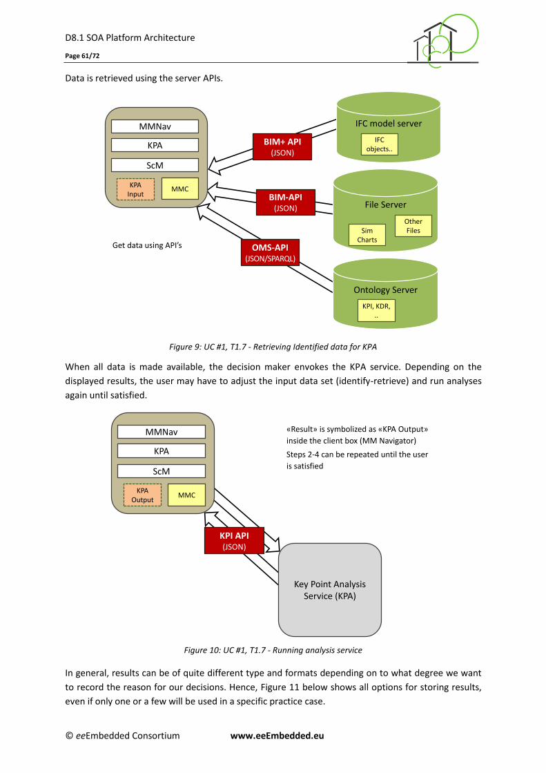
D8.1 SOA Platform Architecture
Page 61/72
© eeEmbedded Consortium www.eeEmbedded.eu
Data is retrieved using the server APIs.
Figure 9: UC #1, T1.7 - Retrieving Identified data for KPA
When all data is made available, the decision maker envokes the KPA service. Depending on the
displayed results, the user may have to adjust the input data set (identify-retrieve) and run analyses
again until satisfied.
Figure 10: UC #1, T1.7 - Running analysis service
In general, results can be of quite different type and formats depending on to what degree we want
to record the reason for our decisions. Hence, Figure 11 below shows all options for storing results,
even if only one or a few will be used in a specific practice case.
Get data using API’s
File Server
Ontology Server
KPI, KDR, ..
IFC model server
IFC objects..
BIM+ API(JSON)
BIM-API(JSON)
OMS-API(JSON/SPARQL)
MMC
MMNav
KPA
ScM
KPA Input
Sim Charts
Other Files
«Result» is symbolized as «KPA Output»
inside the client box (MM Navigator)
Steps 2-4 can be repeated until the user
is satisfied
MMC
MMNav
KPA
ScM
KPI API(JSON)
Key Point Analysis Service (KPA)
KPA Output
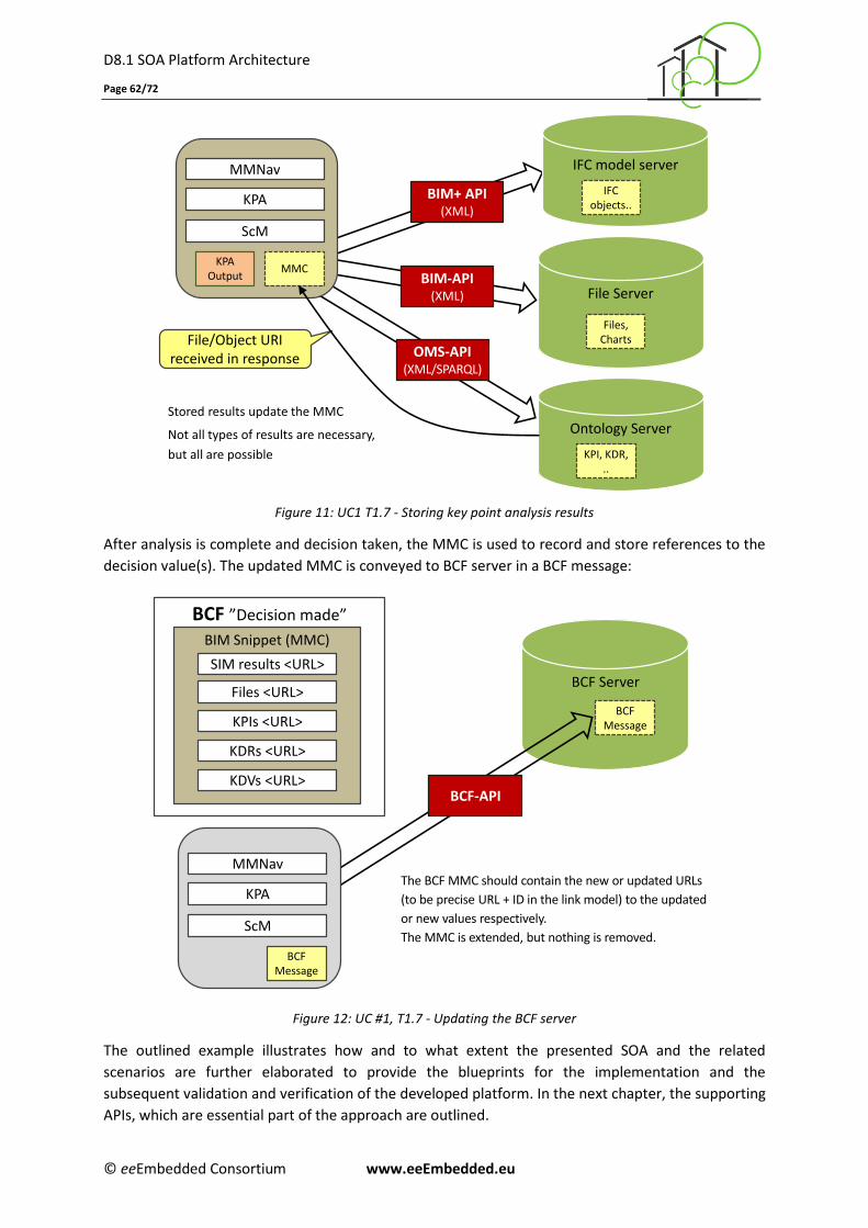
D8.1 SOA Platform Architecture
Page 62/72
© eeEmbedded Consortium www.eeEmbedded.eu
Figure 11: UC1 T1.7 - Storing key point analysis results
After analysis is complete and decision taken, the MMC is used to record and store references to the
decision value(s). The updated MMC is conveyed to BCF server in a BCF message:
Figure 12: UC #1, T1.7 - Updating the BCF server
The outlined example illustrates how and to what extent the presented SOA and the related
scenarios are further elaborated to provide the blueprints for the implementation and the
subsequent validation and verification of the developed platform. In the next chapter, the supporting
APIs, which are essential part of the approach are outlined.
File Server
Files,Charts
Ontology Server
KPI, KDR, ..
IFC model server
IFC objects..
BIM+ API(XML)
BIM-API(XML)
OMS-API(XML/SPARQL)
MMC
MMNav
KPA
ScM
Stored results update the MMC
Not all types of results are necessary,
but all are possible
File/Object URI received in response
KPA Output
The BCF MMC should contain the new or updated URLs
(to be precise URL + ID in the link model) to the updated
or new values respectively.
The MMC is extended, but nothing is removed.
BCF Server
BCF Message
BCF-API
BCF ”Decision made”
BIM Snippet (MMC)
KPIs <URL>
SIM results <URL>
Files <URL>
KDRs <URL>
KDVs <URL>
BCF Message
MMNav
KPA
ScM
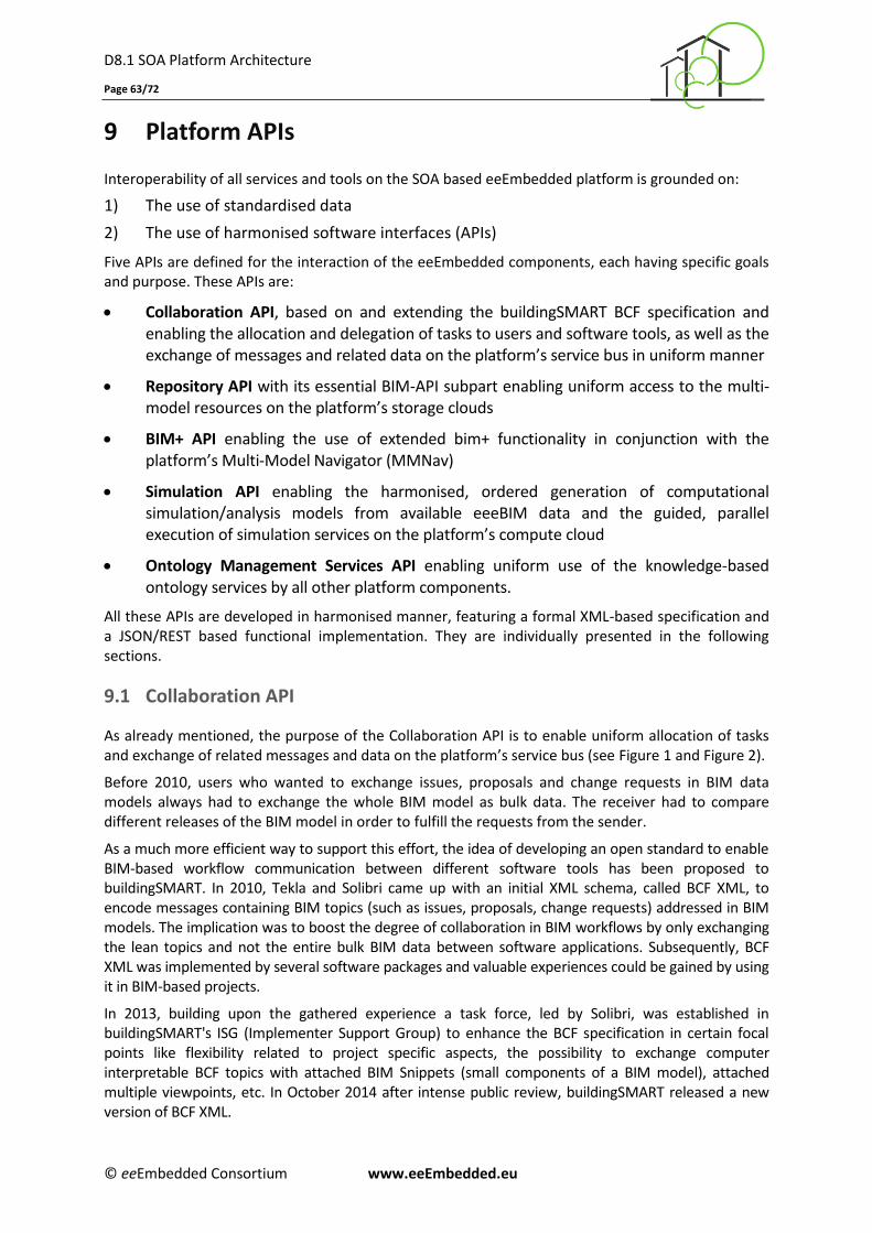
D8.1 SOA Platform Architecture
Page 63/72
© eeEmbedded Consortium www.eeEmbedded.eu
9 Platform APIs
Interoperability of all services and tools on the SOA based eeEmbedded platform is grounded on:
1) The use of standardised data
2) The use of harmonised software interfaces (APIs)
Five APIs are defined for the interaction of the eeEmbedded components, each having specific goals and purpose. These APIs are:
Collaboration API, based on and extending the buildingSMART BCF specification and enabling the allocation and delegation of tasks to users and software tools, as well as the exchange of messages and related data on the platform’s service bus in uniform manner
Repository API with its essential BIM-API subpart enabling uniform access to the multi-model resources on the platform’s storage clouds
BIM+ API enabling the use of extended bim+ functionality in conjunction with the platform’s Multi-Model Navigator (MMNav)
Simulation API enabling the harmonised, ordered generation of computational simulation/analysis models from available eeeBIM data and the guided, parallel execution of simulation services on the platform’s compute cloud
Ontology Management Services API enabling uniform use of the knowledge-based ontology services by all other platform components.
All these APIs are developed in harmonised manner, featuring a formal XML-based specification and a JSON/REST based functional implementation. They are individually presented in the following sections.
9.1 Collaboration API
As already mentioned, the purpose of the Collaboration API is to enable uniform allocation of tasks and exchange of related messages and data on the platform’s service bus (see Figure 1 and Figure 2).
Before 2010, users who wanted to exchange issues, proposals and change requests in BIM data models always had to exchange the whole BIM model as bulk data. The receiver had to compare different releases of the BIM model in order to fulfill the requests from the sender.
As a much more efficient way to support this effort, the idea of developing an open standard to enable BIM-based workflow communication between different software tools has been proposed to buildingSMART. In 2010, Tekla and Solibri came up with an initial XML schema, called BCF XML, to encode messages containing BIM topics (such as issues, proposals, change requests) addressed in BIM models. The implication was to boost the degree of collaboration in BIM workflows by only exchanging the lean topics and not the entire bulk BIM data between software applications. Subsequently, BCF XML was implemented by several software packages and valuable experiences could be gained by using it in BIM-based projects.
In 2013, building upon the gathered experience a task force, led by Solibri, was established in buildingSMART's ISG (Implementer Support Group) to enhance the BCF specification in certain focal points like flexibility related to project specific aspects, the possibility to exchange computer interpretable BCF topics with attached BIM Snippets (small components of a BIM model), attached multiple viewpoints, etc. In October 2014 after intense public review, buildingSMART released a new version of BCF XML.
D8.1 SOA Platform Architecture
Page 64/72
© eeEmbedded Consortium www.eeEmbedded.eu
In the same year, as a second major objective of the BCF task force, a web service based on a BCF API was introduced by eeE partner IAB (the Institute of applied Building Informatics in Munich, Germany). The idea behind this is to exchange BCF topics not only manually or by e-mail attachments, but automated via a standardized RESTful API. This API was released in February 2015.
The BCF API, extended with additional energy-related concepts in the foreseen “extension” section of the API schema is now used as the Collaboration REST API in the eeEmbedded platform. Detailed information regarding the formal API specification is available at the project’s web site and at https://github.com/BuildingSMART/BCF-API.
A BCF topic is the main unit of work in a collaborative process. It represents a single issue within a project context. Topics are mainly composed of descriptive elements such as error descriptions or user comments, BIM data such as viewpoints and geometry information as well as file attachments like BIM snippets or document reference.
BCF Snippets, introduced to transport model parts/components related to a specific BIM topic, are used in eeEmbedded in highly structured manner. They contain computer interpretable Link Models providing references to (parts of) one or more models related to the BCF topic and described formally in a so called Multi-Model Container (MMC). Such containers may encapsulate the actual model data but would typically only hold references to the data which are then accessed using the Repository API described in the next section. This facilitates greatly the efficiency of user and service communication.
Issue tracking is made possible via references, allowing users to track topics throughout the project from the first occurrence to their finalization.
EXAMPLE: Downloading a single BCF topic via the BCF REST API
REQUEST: https://bim--it.net/bcf/1.0/topics/095d901a-6e5b-4f73-9693-ae805a4a9b7c
RESPONSE:
{
"guid": "095d901a-6e5b-4f73-9693-ae805a4a9b7c",
"title": "Handover Architectural Model",
"creation_date": "2015-05-13T16:52:47",
"creation_author": "[email protected]",
"topic_type": "eeE - Handover",
"topic_status": "Key Point complete",
"reference_link": "https://bim--it.net/i/iab/Files/Arch_Variant_01.ifc",
"priority": "Medium",
"labels": [
"Architectural",
"Simulation",
"BIM-Manager",
"Decision Making",
"LCC",
"LCA",
"FM",
"BACS",
"HVAC",
"eSIM"
],
"bim_snippet": {
"snippet_type": "JSON_Provision_Model",
"is_external": true,
"reference": "https://bim--it.net/i/iab/Files/Arch_Variant_01.ifc",
"reference_schema": “https://bim--it.net/i/iab/Files/Request.json”
}
}
D8.1 SOA Platform Architecture
Page 65/72
© eeEmbedded Consortium www.eeEmbedded.eu
9.2 Repository API
The purpose of the Repository API us to enable harmonized and efficient access to all common
information resources (BIM, ESIM and other model and document data) in the storage clouds of the
eeEmbedded platform.
A repository is a place in which an aggregation of data is kept and maintained in an organized way. A
repository may be directly accessible to users or may be a place from which specific databases, files,
or documents are obtained for further relocation or distribution in a network. It may be just the
aggregation of data itself into some accessible place of storage or it may also imply some ability to
selectively extract data.
The goal of the eeE Repository API specification is to provide a transparent interface that supports
the unified access to version controlled repository resources in the cloud, but is independent from
the underlying technologies and data storage. Relying on a RESTful architecture it allows to query
resources individually using their unique URI or together as a collection of resources based on their
common type, also referenced by a URI. A closely related concept of a persistent storage
management, as is the case with the eeEmbedded repository, is formed by the functions create,
read, update and delete (CRUD). Therefore, the only required information for a client to interact with
a repository/server is the location of the resource and the intended action. This allows ubiquitous
access to the eeEmbedded repository assets .
CRUD functions are available for the following main resources:
Project - contains domains and models.
Domain - generalized concept of discipline or usage area like "Architect" "HVAC", "LCC Data"
and similar.
Model - part of project that can be represented as a single file. A model is assigned to a
domain. Each model can exist in several versions, usually representing evolvement over time -
that is, versions are not representing variants of the same model.
Specifically for the access to Model data a subpart of the Repository API called BIM-API has been
developed to provide common vendor and server independent access to BIM data. It includes the
following basic functions that can be used regardless of the accessed repository or BIM server:
Create Model
Delete Model
Download Model
List Models
Update Model
Upload Model
Detailed descriptions of the Repository API can be found at https://github.com/BIMit/ModelAPI,
which represents also the reference documentation to be used for the implementation of the API.
It is important to mention that the eeE Repository API does not specify queries on object level or in
other words, it does not provide defined model filters because repository vendors use their own
proprietary storage models. For that, a CRUD operation is always handling the whole resource (e.g.
file) and never a partial resource. The latter is accomplished by generalized model management
services (MMS) which are developed in WP4 and described in deliverable D4.4.
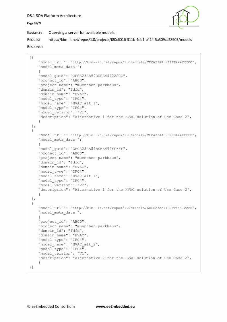
D8.1 SOA Platform Architecture
Page 66/72
© eeEmbedded Consortium www.eeEmbedded.eu
EXAMPLE: Querying a server for available models.
REQUEST: https://bim--it.net/repos/1.0/projects/f80c6016-311b-4eb1-b414-5a309ca28903/models
RESPONSE:
[{
"model_url ": "http://bim--it.net/repos/1.0/models/CFCA23AA59BEEE444222CC",
"model_meta_data ":
{
"model_guid": "CFCA23AA59BEEE444222CC",
"project_id": "ABCD",
"project_name": "muenchen-parkhaus",
"domain_id": "fdfd",
"domain_name": "HVAC",
"model_type": "IFC4",
"model_name": "HVAC_alt_1",
"model_type": "IFC4",
"model_version": "V1",
"description": "Alternative 1 for the HVAC solution of Use Case 2",
}
},
{
"model_url ": "http://bim--it.net/repos/1.0/models/CFCA23AA59BEEE444FFFFF",
"model_meta_data ":
{
"model_guid": "CFCA23AA59BEEE444FFFFF",
"project_id": "ABCD",
"project_name": "muenchen-parkhaus",
"domain_id": "fdfd",
"domain_name": "HVAC",
"model_type": "IFC4",
"model_name": "HVAC_alt_1",
"model_type": "IFC4",
"model_version": "V2",
"description": "Alternative 1 for the HVAC solution of Use Case 2",
}
},
{
"model_url ": "http://bim--it.net/repos/1.0/models/ADFE23AA11BCFF444122BB",
"model_meta_data ":
{
"project_id": "ABCD",
"project_name": "muenchen-parkhaus",
"domain_id": "fdfd",
"domain_name": "HVAC",
"model_type": "IFC4",
"model_name": "HVAC_alt_2",
"model_type": "IFC4",
"model_version": "V1",
"description": "Alternative 2 for the HVAC solution of Use Case 2",
}
}]
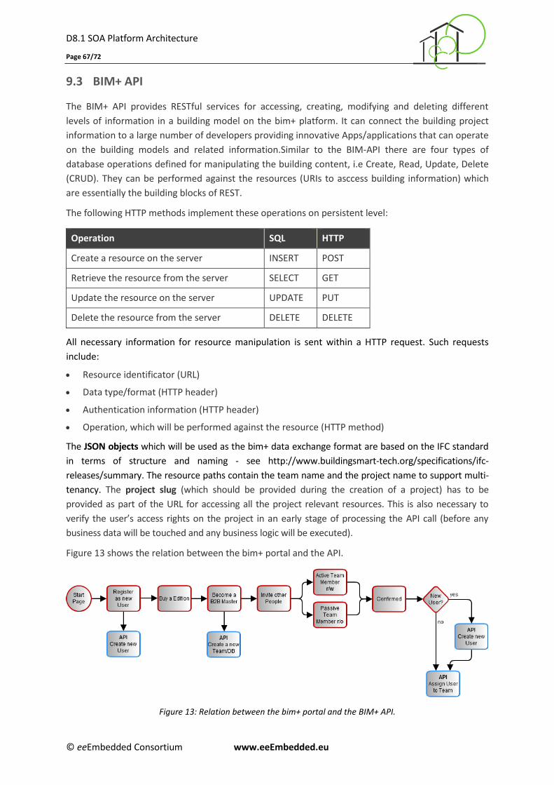
D8.1 SOA Platform Architecture
Page 67/72
© eeEmbedded Consortium www.eeEmbedded.eu
9.3 BIM+ API
The BIM+ API provides RESTful services for accessing, creating, modifying and deleting different
levels of information in a building model on the bim+ platform. It can connect the building project
information to a large number of developers providing innovative Apps/applications that can operate
on the building models and related information.Similar to the BIM-API there are four types of
database operations defined for manipulating the building content, i.e Create, Read, Update, Delete
(CRUD). They can be performed against the resources (URIs to asccess building information) which
are essentially the building blocks of REST.
The following HTTP methods implement these operations on persistent level:
Operation SQL HTTP
Create a resource on the server INSERT POST
Retrieve the resource from the server SELECT GET
Update the resource on the server UPDATE PUT
Delete the resource from the server DELETE DELETE
All necessary information for resource manipulation is sent within a HTTP request. Such requests
include:
Resource identificator (URL)
Data type/format (HTTP header)
Authentication information (HTTP header)
Operation, which will be performed against the resource (HTTP method)
The JSON objects which will be used as the bim+ data exchange format are based on the IFC standard
in terms of structure and naming - see http://www.buildingsmart-tech.org/specifications/ifc-
releases/summary. The resource paths contain the team name and the project name to support multi-
tenancy. The project slug (which should be provided during the creation of a project) has to be
provided as part of the URL for accessing all the project relevant resources. This is also necessary to
verify the user’s access rights on the project in an early stage of processing the API call (before any
business data will be touched and any business logic will be executed).
Figure 13 shows the relation between the bim+ portal and the API.
Figure 13: Relation between the bim+ portal and the BIM+ API.
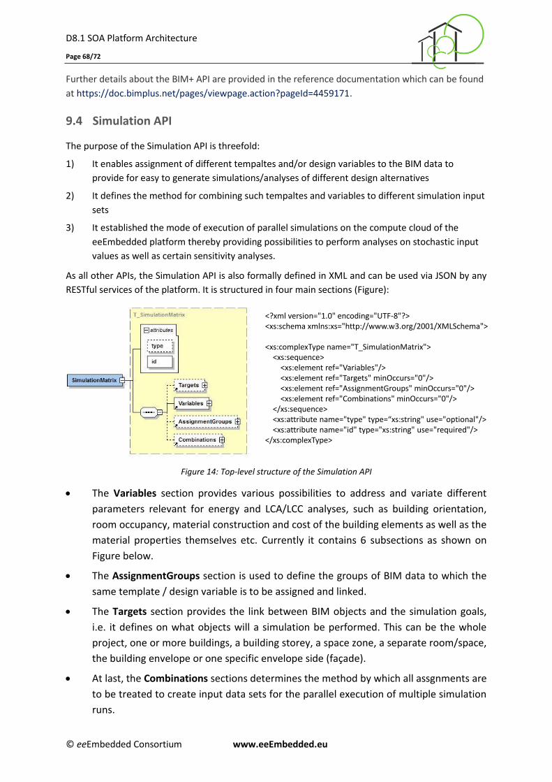
D8.1 SOA Platform Architecture
Page 68/72
© eeEmbedded Consortium www.eeEmbedded.eu
Further details about the BIM+ API are provided in the reference documentation which can be found
at https://doc.bimplus.net/pages/viewpage.action?pageId=4459171.
9.4 Simulation API
The purpose of the Simulation API is threefold:
1) It enables assignment of different tempaltes and/or design variables to the BIM data to
provide for easy to generate simulations/analyses of different design alternatives
2) It defines the method for combining such tempaltes and variables to different simulation input
sets
3) It established the mode of execution of parallel simulations on the compute cloud of the
eeEmbedded platform thereby providing possibilities to perform analyses on stochastic input
values as well as certain sensitivity analyses.
As all other APIs, the Simulation API is also formally defined in XML and can be used via JSON by any
RESTful services of the platform. It is structured in four main sections (Figure):
Figure 14: Top-level structure of the Simulation API
The Variables section provides various possibilities to address and variate different
parameters relevant for energy and LCA/LCC analyses, such as building orientation,
room occupancy, material construction and cost of the building elements as well as the
material properties themselves etc. Currently it contains 6 subsections as shown on
Figure below.
The AssignmentGroups section is used to define the groups of BIM data to which the
same template / design variable is to be assigned and linked.
The Targets section provides the link between BIM objects and the simulation goals,
i.e. it defines on what objects will a simulation be performed. This can be the whole
project, one or more buildings, a building storey, a space zone, a separate room/space,
the building envelope or one specific envelope side (façade).
At last, the Combinations sections determines the method by which all assgnments are
to be treated to create input data sets for the parallel execution of multiple simulation
runs.
<?xml version="1.0" encoding="UTF-8"?><xs:schema xmlns:xs="http://www.w3.org/2001/XMLSchema">
<xs:complexType name="T_SimulationMatrix"><xs:sequence>
<xs:element ref="Variables"/><xs:element ref="Targets" minOccurs="0"/><xs:element ref="AssignmentGroups" minOccurs="0"/><xs:element ref="Combinations" minOccurs="0"/>
</xs:sequence><xs:attribute name="type" type=“xs:string" use="optional"/><xs:attribute name="id" type="xs:string" use="required"/>
</xs:complexType>
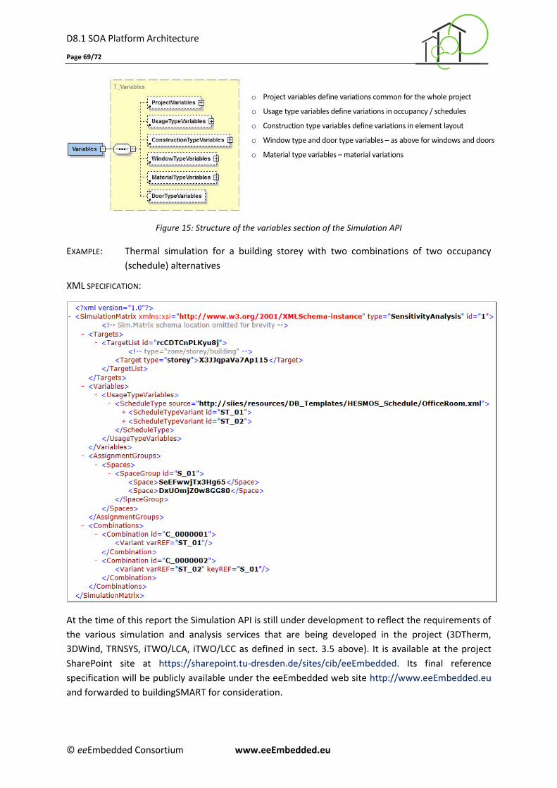
D8.1 SOA Platform Architecture
Page 69/72
© eeEmbedded Consortium www.eeEmbedded.eu
Figure 15: Structure of the variables section of the Simulation API
EXAMPLE: Thermal simulation for a building storey with two combinations of two occupancy
(schedule) alternatives
XML SPECIFICATION:
At the time of this report the Simulation API is still under development to reflect the requirements of
the various simulation and analysis services that are being developed in the project (3DTherm,
3DWind, TRNSYS, iTWO/LCA, iTWO/LCC as defined in sect. 3.5 above). It is available at the project
SharePoint site at https://sharepoint.tu-dresden.de/sites/cib/eeEmbedded. Its final reference
specification will be publicly available under the eeEmbedded web site http://www.eeEmbedded.eu
and forwarded to buildingSMART for consideration.
o Project variables define variations common for the whole project
o Usage type variables define variations in occupancy / schedules
o Construction type variables define variations in element layout
o Window type and door type variables – as above for windows and doors
o Material type variables – material variations
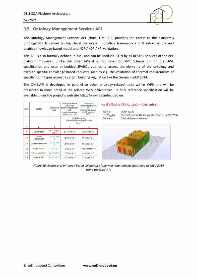
D8.1 SOA Platform Architecture
Page 70/72
© eeEmbedded Consortium www.eeEmbedded.eu
9.5 Ontology Management Services API
The Ontology Management Services API (short: OMS-API) provides the access to the platform’s
ontology which defines on high level the overall modelling framework and IT infrastructure and
enables knowledge-based model and KDR / KDP / KPI validation.
This API is also formally defined in XML and can be used via JSON by all RESTful services of the eeE
platform. However, unlike the other APIs it is not based on XML Schema but on the OWL
specification and uses embedded SPARQL queries to access the elements of the ontology and
execute specific knowledge-based requests such as e.g. the validation of thermal requirements of
specific room types against a certain building regulation like the German EnEV 2014.
The OMS-API is developed in parallel to other ontology-related tasks within WP5 and will be
presented in more detail in the related WP5 deliverables. Its final reference specification will be
available under the project’s web site http://www.eeEmbedded.eu.
Figure 16: Example of ontology-based validation of thermal requirements according to EnEV 2014 using the OMS-API
TU Dresden, 22.11.2015
Wall(x) Outer wallsGTuV0.35(x) thermal transmittance greater than 0.35 W(m²*K)Critical(x) Critical thermal element
D8.1 SOA Platform Architecture
Page 71/72
© eeEmbedded Consortium www.eeEmbedded.eu
10 Conclusions
This deliverable presented an approach for the creation of a flexible service-oriented architecture for
the eeEmbedded virtual energy lab and office. The developed Service Oriented Architecture (SOA)
supports multiple data storage technologies such as local servers and cloud solutions and enables
unified integration of various applications. As baseline, the conceptual architecture presented in
deliverable D1.5 was used and extended, updated and restructured.
The platform modules and their components were strictly categorized in functional groups and
presented in compact tabular form. For each component the type (local application, web application,
service etc.), the actors involved in its use and a description are provided. The generic scenario
workflows from D1.5 were reworked, detailed and adapted to current findings. Particular extensions
were made with regard to technical collaboration and information exchange challenges. The specific
detailed workflows from D2.3 were refined for all usage scenarios to ensure that the software
architecture meets all the requirements defined by the scenario workflows.
A hybrid strategy was defined, where the Scenario Manager (ScM) covers the communication for all
high-level tasks specified in BPMN, whereas the BIM Collaboration Format (BCF) will be used both on
the high level by the Scenario Manager and on the subtask level, to deal directly with various data
exchange issues. An example illustrating the further detailing is provided as proof of concept for a
selected subpart of Usage Scenario #1. Hence, it can be concluded that the proposed approach offers
a technical solution that guarantees efficient adaptation and smooth data exchange between user
applications handled by the eeE BCF Service Bus.
The eeE SOA is flexible, modern and could be easily extended. Based on this deliverable result,
a structured design methodology is developed for covering the gaps in the detailed use cases. Using
the presented service-oriented architecture the collaboration methods for the efficient realisation of
the envisaged collaborative holistic design lab and office will be developed in Task T8.2. The
deliverable at hand is also the basis for the prototype of the context-aware Scenario Manager that
will be presented in D8.3 to automate the design and BIM processes and the simulation services.
Finally the planned services, tools and data models will be evaluated in a test bed, which will be
reported in deliverable D8.4.
D8.1 SOA Platform Architecture
Page 72/72
© eeEmbedded Consortium www.eeEmbedded.eu
11 References
Baumgärtel, K., Katranuschkov, P., Hollmann, A., Laine, T., Protopsaltis, B., Dolenc, M., Klinc, R.,
Guðnason, G., Balaras, C. (2013): ISES Deliverable D2.2: Architecture and Components of the
Virtual Lab Platform, © ISES Consortium, Brussels.
Bell, M. (2008): Service-Oriented Modeling (SOA): Service Analysis, Design, and Architecture, Wiley &
Sons, ISBN: 978-0-470-14111-3, 384 p.
Calleja Rodriguez, G., Guruz, R., (2014): eeEmbedded Deliverable D1.3: Interoperability and Collabo-
ration Requirements, © eeEmbedded Consortium, Brussels.
Geißler, M.C., Guruz, R., van Woudenberg, W. (2014): eeEmbedded Deliverable D1.2: Use Case
Scenarios and Requirements Specification, © eeEmbedded Consortium, Brussels.
Guruz, R., Calleja Rodriguez, G., Geißler, M.-C. (2015): eeEmbedded Deliverable D2.3: Holistic KPI
Based Design Methodology, © eeEmbedded Consortium, Brussels.
IFC4 (1996-2013): Industry Foundation Classes Release 4, http://www.buildingsmart-
tech.org/ifc/IFC4/final/html/, © buildingSMART International Ltd 1996-2013
ISO 16739 (2013): Industry Foundation Classes (IFC) for data sharing in the construction and facility
management industries, Interantional Organisation for Standardization, Geneva, Switzerland.
Linhard, K., Dangle, G. (2015): BCF REST API, Web service specification for BIM Collaboration Format,
https://github.com/BuildingSMART/BCF-API, © BuildingSmart
Linhard, K., Dangle, G., Tøn, A. et. al. (2015): Energy Efficient Buildings Repository Services,
https://github.com/BIMit/ModelAPI
OASIS (2012): Reference Architecture Foundation for Service Oriented Architecture Version 1.0,
Committee Specification 01, 04 December 2012, http://docs.oasis-open.org/soa-rm/soa-
ra/v1.0/cs01/soa-ra-v1.0-cs01.pdf, 118 p., © OASIS Open 2012.
OMG (1997-2015): Unified Modelling Language (UML) v 2.5, http://www.omg.org/spec/UML
/2.5/PDF, © Object Management Group 1997-2015.
Richardson L., Ruby S. (2008): RESTful Web Services, O’Reilly Media Inc., ISBN 0596554605, 454 p.
Richardson L., Amundsen M., Ruby S. (2013): RESTful Web APIs, O’Reilly, ISBN 1449358063, 406 p.
Solvik, K., Kaiser, J. (2014): eeEmbedded Deliverable D1.4: Requirements for Knowledge-Based
Design Support and Templates, © eeEmbedded Consortium, Brussels.
W3C (2004): XML Schema – Pt. 0: Primer, Pt. 1: Structures, Pt. 2: Datatypes,
[http://www.w3.org/TR/]xmlschema-0/, 2004/REC-xmlschema-1-20041028/structures.html,
2004/REC-xmlschema-1-20041028/datatypes.html
W3C (2012): OWL 2 Web Ontology Language (Second Edition), W3C Recommendation 11 Dec. 2012,
http://www.w3.org/TR/owl2-overview/
W3C (2013): SPARQL 1.1 Overview, W3C Rec. 21 Mar. 2013, http://www.w3.org/TR/sparql11-
overview/
Zellner R., Guruz R., Mosch M., Katranuschkov P., Tøn A. & Kaiser J. (2015); eeEmbedded Deliverable
D1.5: System Architecture of the Virtual Holistic Design Lab and Office, © eeEmbedded
Consortium, Brussels.