Effects of a Local Interstellar Magnetic Field on …¬€ects of a Local Interstellar Magnetic...
13
arXiv:astro-ph/0603318v1 13 Mar 2006 Effects of a Local Interstellar Magnetic Field on Voyager 1 and 2 Observations Merav Opher 1 George Mason University, 4400 University Drive, Fairfax, VA 22030 [email protected] Edward C. Stone 2 California Institute of Technology, Pasadena, CA 91125 [email protected] Paulett C. Liewer 3 Jet Propulsion Laboratory, California Institute of Technology, Pasadena, CA 91109 [email protected] ABSTRACT We show that that an interstellar magnetic field can produce a north/south asymmetry in solar wind termination shock. Using Voyager 1 and 2 measure- ments, we suggest that the angle α between the interstellar wind velocity and magnetic field is 30 ◦ <α< 60 ◦ . The distortion of the shock is such that ter- mination shock particles could stream outward along the spiral interplanetary magnetic field connecting Voyager 1 to the shock when the spacecraft was within ∼ 2 AU of the shock. The shock distortion is larger in the southern hemisphere, and Voyager 2 could be connected to the shock when it is within ∼ 5 AU of the shock, but with particles from the shock streaming inward along the field. Tighter constraints on the interstellar magnetic field should be possible when Voyager 2 crosses the shock in the next several years. Subject headings: interplanetary medium – ISM:kinematics and dynamics – MHD:solar wind – Sun:magnetic fields
Transcript of Effects of a Local Interstellar Magnetic Field on …¬€ects of a Local Interstellar Magnetic...
arX
iv:a
stro
-ph/
0603
318v
1 1
3 M
ar 2
006
Effects of a Local Interstellar Magnetic Field on Voyager 1 and 2
Observations
Merav Opher1
George Mason University, 4400 University Drive, Fairfax, VA 22030
Edward C. Stone2
California Institute of Technology, Pasadena, CA 91125
Paulett C. Liewer3
Jet Propulsion Laboratory, California Institute of Technology, Pasadena, CA 91109
ABSTRACT
We show that that an interstellar magnetic field can produce a north/south
asymmetry in solar wind termination shock. Using Voyager 1 and 2 measure-
ments, we suggest that the angle α between the interstellar wind velocity and
magnetic field is 30◦ < α < 60◦. The distortion of the shock is such that ter-
mination shock particles could stream outward along the spiral interplanetary
magnetic field connecting Voyager 1 to the shock when the spacecraft was within
∼ 2 AU of the shock. The shock distortion is larger in the southern hemisphere,
and Voyager 2 could be connected to the shock when it is within ∼ 5 AU of
the shock, but with particles from the shock streaming inward along the field.
Tighter constraints on the interstellar magnetic field should be possible when
Voyager 2 crosses the shock in the next several years.
Subject headings: interplanetary medium – ISM:kinematics and dynamics – MHD:solar
wind – Sun:magnetic fields
– 2 –
1. Introduction
The motion of solar system through the interstellar medium with a velocity of 25.5 km/s
compresses the heliosphere, producing a comet-like shape with an extended tail. The helio-
sphere is created by the supersonic solar wind which abruptly slows, forming a termination
shock as it approaches contact with the interstellar medium at the heliopause. Beyond the
heliopause, the interstellar wind contains neutral atoms, mainly hydrogen and helium, and
ions that carry the frozen-in interstellar magnetic field.
The twin Voyager spacecraft are probing the northern and southern hemispheres of the
heliosphere. On December 16, 2004, Voyager 1 crossed the termination shock at 94 AU and
began exploring the heliosheath (Burlaga et al. 2005; Decker et al. 2005a; Stone et al. 2005).
Voyager 1 is now beyond 98 AU at 34.1◦ in latitude and 178◦ in longitude, while Voyager 2
is beyond 78 AU at −26.2◦ in latitude and 213◦ in longitude (solar ecliptic coordinates). In
mid 2002, Voyager 1 began observing strong energetic beams of termination shock particles
(TSPs), streaming outward along the spiral magnetic field upstream the shock. Jokipii,
Giacoloni, & Kota (2004) and Stone et al. (2005) suggested that the upstream beaming
resulted from a non-spherical shock with the spiral interplanetary magnetic field line crossing
the shock (the source of TSPs) and returning to the supersonic solar wind before reaching
Voyager 1.
An interstellar magnetic field oriented obliquely to the interstellar velocity can produce
a lateral or north-south asymmetry in the heliospheric shape(Pogorolev & Matsuda 1996;
Ratkiewicz et al. 1998). However, the direction and intensity of the local interstellar mag-
netic field are not well constrained. Based on the polarization of light from nearby stars,
Frisch (1990) suggested that the magnetic eld direction is parallel to the galactic plane (and
directed toward l ∼ 70◦). The source distribution of the Voyager 3kHz radio emission is
also parallel to that plane (Kurth & Gurnett 2003). On the other hand, Lallement et al.
(2005) found from resonantly scattered solar Lyman-α radiation that the flow direction of
interstellar neutral hydrogen differs from that of helium by 4◦ in a direction consistent with
an interstellar magnetic field plane inclined 60◦ from the galactic plane. This deflection has
been demonstrated by model calculations (Izmodenov, Alexashov, & Myasnikov 2005). In
this paper, we will assume the interstellar field is parallel to this plane, which we will refer
to as the the H-deflection plane (HDP). There are few previous MHD models of the inter-
action of the solar and interstellar winds that include both the solar magnetic field and the
interstellar magnetic field(Linde et al. 1998; Pogorolev, Zank, & Ogino 2004; McNutt et al.
1999; Washimi & Tanaka 2001).
In this paper we explore the non-spherical shape of the termination shock and the
orientation of the interstellar magnetic field and show that observations from Voyager 1 and
– 3 –
2 may provide information on the inclination and strength of the interstellar magnetic field.
2. Results
The model is based on the BATS-R-US code, a three-dimensional magnetohdyrody-
namic (MHD) parallel, adaptive grid code developed by University of Michigan(Gombosi,
Powell, & de Zeeuw 1994) and adapted by Opher et al. (2003, 2004) for the outer heliosphere.
We used a grid ranging from 1.5 AU to 20 AU with an inner boundary at 30 AU and an
outer boundary at −1500 AU and 1500 AU in the y and z directions and at −800 AU
to 800 AU in the x direction. The solar magnetic field axis was aligned with the solar
rotation axis with a 26 days solar rotation period. The solar wind was taken as uniform
450 km/s; only the ionized component was included. The solar wind at the inner boundary
was n = 7.8× 10⁻³cm−3, T = 1.6× 10³ K, and a Parker spiral magnetic field of 2µG at the
equator. For the interstellar wind, we used n = 0.07 cm−3 and T = 104 K (Frisch 1996).
We considered interstellar magnetic fields in the H-deflection plane (HDP) with differ-
ent inclination angles α, where α is the angle between the interstellar magnetic field and
interstellar wind velocity. The coordinate system has the interstellar velocity direction in
the +x direction and the z-axis as the solar rotation axis of the sun, with y completing the
right handed coordinate system. In this coordinate system, Voyager 1 is at 29.1◦ in latitude
and 213.4◦ in longitude and Voyager 2 is at −31.2◦ and 178.4◦ in longitude, which ignores
the 7.25◦ tilt of the solar equator with respect to the ecliptic plane.
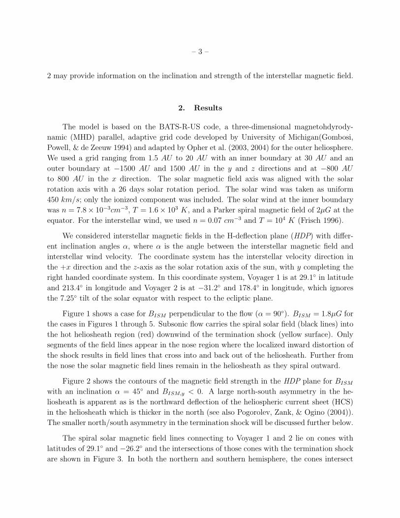
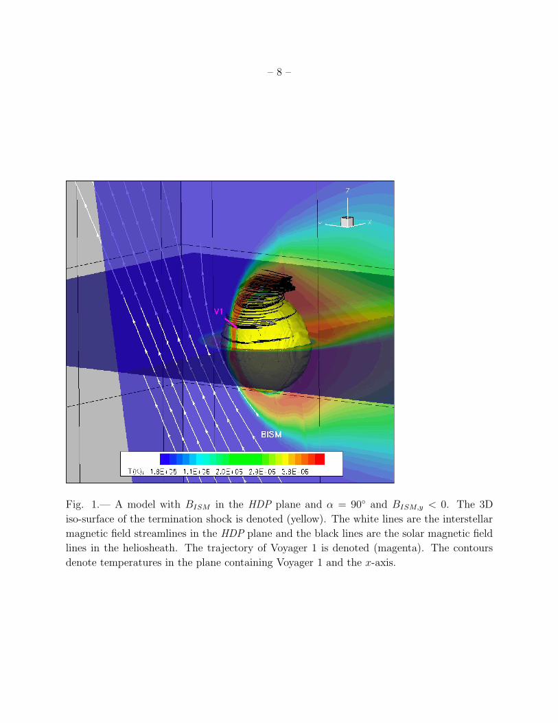
Figure 1 shows a case for BISM perpendicular to the flow (α = 90◦). BISM = 1.8µG for
the cases in Figures 1 through 5. Subsonic flow carries the spiral solar field (black lines) into
the hot heliosheath region (red) downwind of the termination shock (yellow surface). Only
segments of the field lines appear in the nose region where the localized inward distortion of
the shock results in field lines that cross into and back out of the heliosheath. Further from
the nose the solar magnetic field lines remain in the heliosheath as they spiral outward.
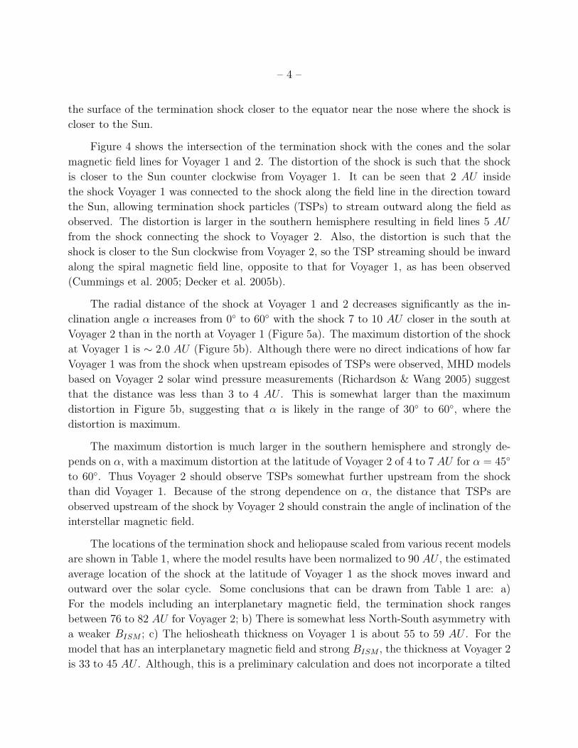
Figure 2 shows the contours of the magnetic field strength in the HDP plane for BISM
with an inclination α = 45◦ and BISM,y < 0. A large north-south asymmetry in the he-
liosheath is apparent as is the northward deflection of the heliospheric current sheet (HCS)
in the heliosheath which is thicker in the north (see also Pogorolev, Zank, & Ogino (2004)).
The smaller north/south asymmetry in the termination shock will be discussed further below.
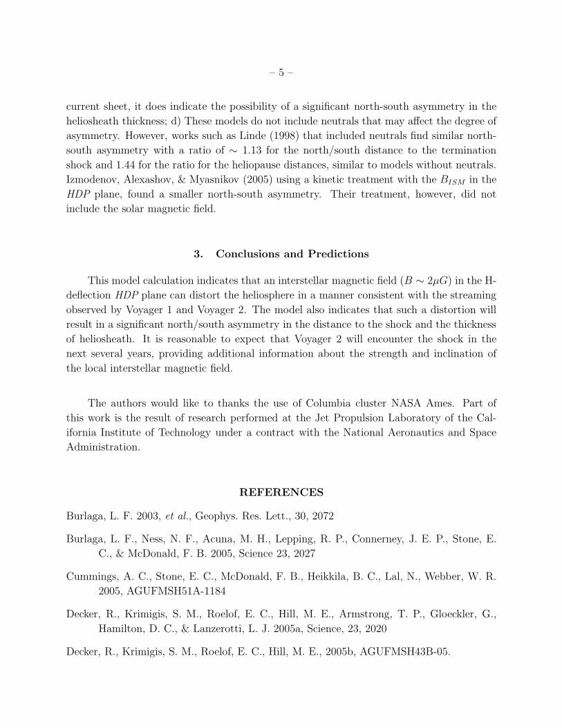
The spiral solar magnetic field lines connecting to Voyager 1 and 2 lie on cones with
latitudes of 29.1◦ and −26.2◦ and the intersections of those cones with the termination shock
are shown in Figure 3. In both the northern and southern hemisphere, the cones intersect
– 4 –
the surface of the termination shock closer to the equator near the nose where the shock is
closer to the Sun.
Figure 4 shows the intersection of the termination shock with the cones and the solar
magnetic field lines for Voyager 1 and 2. The distortion of the shock is such that the shock
is closer to the Sun counter clockwise from Voyager 1. It can be seen that 2 AU inside
the shock Voyager 1 was connected to the shock along the field line in the direction toward
the Sun, allowing termination shock particles (TSPs) to stream outward along the field as
observed. The distortion is larger in the southern hemisphere resulting in field lines 5 AU
from the shock connecting the shock to Voyager 2. Also, the distortion is such that the
shock is closer to the Sun clockwise from Voyager 2, so the TSP streaming should be inward
along the spiral magnetic field line, opposite to that for Voyager 1, as has been observed
(Cummings et al. 2005; Decker et al. 2005b).
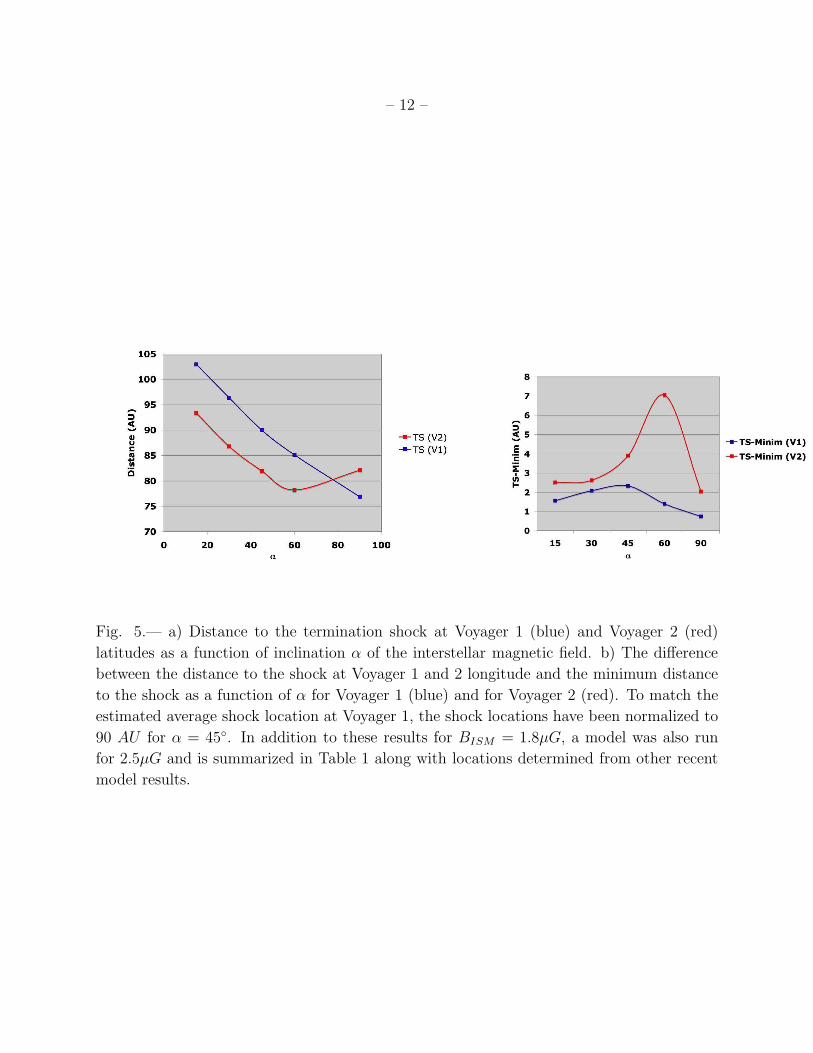
The radial distance of the shock at Voyager 1 and 2 decreases significantly as the in-
clination angle α increases from 0◦ to 60◦ with the shock 7 to 10 AU closer in the south at
Voyager 2 than in the north at Voyager 1 (Figure 5a). The maximum distortion of the shock
at Voyager 1 is ∼ 2.0 AU (Figure 5b). Although there were no direct indications of how far
Voyager 1 was from the shock when upstream episodes of TSPs were observed, MHD models
based on Voyager 2 solar wind pressure measurements (Richardson & Wang 2005) suggest
that the distance was less than 3 to 4 AU . This is somewhat larger than the maximum
distortion in Figure 5b, suggesting that α is likely in the range of 30◦ to 60◦, where the
distortion is maximum.
The maximum distortion is much larger in the southern hemisphere and strongly de-
pends on α, with a maximum distortion at the latitude of Voyager 2 of 4 to 7 AU for α = 45◦
to 60◦. Thus Voyager 2 should observe TSPs somewhat further upstream from the shock
than did Voyager 1. Because of the strong dependence on α, the distance that TSPs are
observed upstream of the shock by Voyager 2 should constrain the angle of inclination of the
interstellar magnetic field.
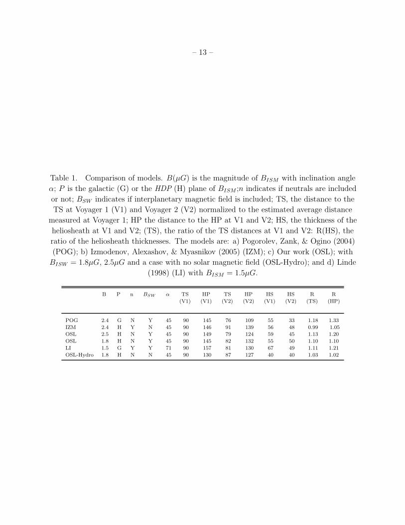
The locations of the termination shock and heliopause scaled from various recent models
are shown in Table 1, where the model results have been normalized to 90 AU , the estimated
average location of the shock at the latitude of Voyager 1 as the shock moves inward and
outward over the solar cycle. Some conclusions that can be drawn from Table 1 are: a)
For the models including an interplanetary magnetic field, the termination shock ranges
between 76 to 82 AU for Voyager 2; b) There is somewhat less North-South asymmetry with
a weaker BISM ; c) The heliosheath thickness on Voyager 1 is about 55 to 59 AU . For the
model that has an interplanetary magnetic field and strong BISM , the thickness at Voyager 2
is 33 to 45 AU . Although, this is a preliminary calculation and does not incorporate a tilted
– 5 –
current sheet, it does indicate the possibility of a significant north-south asymmetry in the
heliosheath thickness; d) These models do not include neutrals that may affect the degree of
asymmetry. However, works such as Linde (1998) that included neutrals find similar north-
south asymmetry with a ratio of ∼ 1.13 for the north/south distance to the termination
shock and 1.44 for the ratio for the heliopause distances, similar to models without neutrals.
Izmodenov, Alexashov, & Myasnikov (2005) using a kinetic treatment with the BISM in the
HDP plane, found a smaller north-south asymmetry. Their treatment, however, did not
include the solar magnetic field.
3. Conclusions and Predictions
This model calculation indicates that an interstellar magnetic field (B ∼ 2µG) in the H-
deflection HDP plane can distort the heliosphere in a manner consistent with the streaming
observed by Voyager 1 and Voyager 2. The model also indicates that such a distortion will
result in a significant north/south asymmetry in the distance to the shock and the thickness
of heliosheath. It is reasonable to expect that Voyager 2 will encounter the shock in the
next several years, providing additional information about the strength and inclination of
the local interstellar magnetic field.
The authors would like to thanks the use of Columbia cluster NASA Ames. Part of
this work is the result of research performed at the Jet Propulsion Laboratory of the Cal-
ifornia Institute of Technology under a contract with the National Aeronautics and Space
Administration.
REFERENCES
Burlaga, L. F. 2003, et al., Geophys. Res. Lett., 30, 2072
Burlaga, L. F., Ness, N. F., Acuna, M. H., Lepping, R. P., Connerney, J. E. P., Stone, E.
C., & McDonald, F. B. 2005, Science 23, 2027
Cummings, A. C., Stone, E. C., McDonald, F. B., Heikkila, B. C., Lal, N., Webber, W. R.
2005, AGUFMSH51A-1184
Decker, R., Krimigis, S. M., Roelof, E. C., Hill, M. E., Armstrong, T. P., Gloeckler, G.,
Hamilton, D. C., & Lanzerotti, L. J. 2005a, Science, 23, 2020
Decker, R., Krimigis, S. M., Roelof, E. C., Hill, M. E., 2005b, AGUFMSH43B-05.
– 6 –
Frisch, P. C. 1990, Physics of the Outer Heliosphere, 19
Frisch, P. C. 1996, Space Sci. Rev. 78, 213
Gombosi, T., Powell, K. G. & de Zeeuw, D. L. 1994, J. Geophys. Res., 99, 21525
Gurnett, D. A. & Kurth, W. S. 2005, Science, 23, 2025
Izmodenov, V., Alexashov, D., & Myasnikov, A. 2005, Astron. Astrophys. 437, L35
Jokipii, J. R., Giacalone, J., Kota, J. 2004, ApJ611, L141
Lallement, R., Quemerais, E., J. L. Bertaux, S. Ferron, D. Koutroumpa, R. Pellinen 2005,
Science, 307, 1449
Linde, T. J., Gombosi, T. I., Roe, P. L., Powell, K. G., DeZeeuw, D. L. 1998, J. Geo-
phys. Res.103, 1889
Linde, T. A Three-Dimensional Adaptive Multifluid MHD Model of the Heliosphere, PhD
thesis, Univ. of Michigan 1998.
Kurth, W. S., Gurnett, D. A. 2003, J. Geophys. Res. 108, LIS 2-1
McNutt, R. L., Lyon, J., Goodrich, C.C., Wiltberger, M. 1999, Solar Wind 9 Am. Inst.
Phys. Conf. Proc. 471, 823
Opher, M., Liewer, P. C., Gombosi, T. I., Manchester, W., DeZeeuw, D. L., Sokolov, I.,
Toth, G. 2003, ApJ, 591, L61
Opher, M., Liewer, P. C., Velli, M., Bettarini, L., Gombosi, T. I., Manchester, W., DeZeeuw,
D. L., Toth, G., Sokolov, I. 2004, ApJ, 611, 575
Pogorelov, N., Matsuda, T. 1996, J. Geophys. Res. 103, 237
Pogorolev, N., Zank, G. P., & Ogino, T. 2004, ApJ, 614, 1007
Ratkiewicz, R., Barnes, A., Molvik, G. A., Spreiter, J. R., Stahara, S. S., Vinokur, M.,
Venkateswaran, S. 1998, Astron. Astrophys. 335, 303
Richardson, J. D., Wang, C. 2005, AGUFMSH51A-1186
Stone, E. C., Cummings, A. C., McDonald, F. B., Heikkila, B. C., Lal, N., & Webber, W.
R. 2005, Science 23, 2017
Suess, S. 1993, J. Geophys. Res., 93, 15147
– 7 –
Washimi, H. & Tanaka, T. 2001, Advances in Space Research, 27, 509
Zank, G. P. et al. 1999, Space Sci. Rev., 89, 413
This preprint was prepared with the AAS LATEX macros v5.2.
– 8 –
Fig. 1.— A model with BISM in the HDP plane and α = 90◦ and BISM,y < 0. The 3D
iso-surface of the termination shock is denoted (yellow). The white lines are the interstellar
magnetic field streamlines in the HDP plane and the black lines are the solar magnetic field
lines in the heliosheath. The trajectory of Voyager 1 is denoted (magenta). The contours
denote temperatures in the plane containing Voyager 1 and the x-axis.

– 9 –
Fig. 2.— Contours of magnetic field strength B(nT ) in the HDP plane with α = 45◦ and
BISM,y < 0. The black lines are the interstellar magnetic field and the white arrows denote
the trajectories of Voyager 1 and Voyager 2. The heliospheric current sheet (deep blue) is
deflected northward in the heliosheath.

– 10 –
Fig. 3.— The intersection of the termination shock surface (yellow) with the cone of inter-
planetary field line connecting to Voyager 1 and Voyager 2 (black lines). The trajectories of
Voyager 1 and Voyager 2 are denoted (white arrows) as well as the solar equatorial plane
(red line). BISM is in the HDP plane with α = 45◦ and BISM,y < 0.

– 11 –
Fig. 4.— Expanded views from above of the field line cones in Figure 4. The plane of the
plot is the surface of the interplanetary field line cones, the horizontal line is the intersection
of conical surface with the x − z plane, and the green line indicates the intersection of the
termination shock with that conical surface. a) Spiral magnetic field lines on the Voyager
1 cone are shown; the field line intersecting the shock where Voyager 1 crosses the shock is
labeled 0 AU (black) with red and blue indicating, respectively, magnetic field lines 2.0 AU
and 3.0 AU upwind from the 0 AU line. The red arrow indicates the streaming direction of
the termination shock particles from the shock along the field line to Voyager 1. b) Similar
plot for Voyager 2, showing field lines 3.0 and 5.0 AU upwind of the 0 AU line. Note that
in both views the interplanetary magnetic field spirals outward with distance increasing
clockwise.
– 12 –
Fig. 5.— a) Distance to the termination shock at Voyager 1 (blue) and Voyager 2 (red)
latitudes as a function of inclination α of the interstellar magnetic field. b) The difference
between the distance to the shock at Voyager 1 and 2 longitude and the minimum distance
to the shock as a function of α for Voyager 1 (blue) and for Voyager 2 (red). To match the
estimated average shock location at Voyager 1, the shock locations have been normalized to
90 AU for α = 45◦. In addition to these results for BISM = 1.8µG, a model was also run
for 2.5µG and is summarized in Table 1 along with locations determined from other recent
model results.
– 13 –
Table 1. Comparison of models. B(µG) is the magnitude of BISM with inclination angle
α; P is the galactic (G) or the HDP (H) plane of BISM ;n indicates if neutrals are included
or not; BSW indicates if interplanetary magnetic field is included; TS, the distance to the
TS at Voyager 1 (V1) and Voyager 2 (V2) normalized to the estimated average distance
measured at Voyager 1; HP the distance to the HP at V1 and V2; HS, the thickness of the
heliosheath at V1 and V2; (TS), the ratio of the TS distances at V1 and V2: R(HS), the
ratio of the heliosheath thicknesses. The models are: a) Pogorolev, Zank, & Ogino (2004)
(POG); b) Izmodenov, Alexashov, & Myasnikov (2005) (IZM); c) Our work (OSL); with
BISW = 1.8µG, 2.5µG and a case with no solar magnetic field (OSL-Hydro); and d) Linde
(1998) (LI) with BISM = 1.5µG.
B P n BSW α TS HP TS HP HS HS R R
(V1) (V1) (V2) (V2) (V1) (V2) (TS) (HP)
POG 2.4 G N Y 45 90 145 76 109 55 33 1.18 1.33
IZM 2.4 H Y N 45 90 146 91 139 56 48 0.99 1.05
OSL 2.5 H N Y 45 90 149 79 124 59 45 1.13 1.20
OSL 1.8 H N Y 45 90 145 82 132 55 50 1.10 1.10
LI 1.5 G Y Y 71 90 157 81 130 67 49 1.11 1.21
OSL-Hydro 1.8 H N N 45 90 130 87 127 40 40 1.03 1.02


![Interstellar 2014 - Interstellar 2014 HDCAM [[ENG]]](https://static.fdocuments.us/doc/165x107/577cc0fb1a28aba71191d2d3/interstellar-2014-interstellar-2014-hdcam-eng.jpg)