EECS 3201: Digital Logic Design Lecture 12
25
EECS 3201: Digital Logic Design Lecture 12 Ihab Amer, PhD, SMIEEE, P.Eng.
Transcript of EECS 3201: Digital Logic Design Lecture 12
EECS 3201:
Digital Logic Design
Lecture 12
Ihab Amer, PhD, SMIEEE, P.Eng.

2
Registers
Collections of flip-flops with special
controls and logic
Stored values somehow related (e.g., form
binary value)
Share clock, reset, and set lines
Examples
Shift registers
Counters

3
Four-bits Register
Parallel load
Clock must be inhibited from the circuit if the contents of the register is to be left unchanged (enabling gate)
Performing logic with clock pulses inserts variable delays and may cause the system to go out of synchronism
Solution: Direct the load control input through gates and into the FF inputs

4
Registers with Parallel Load

5
Shift Registers
A Register capable of shifting its content in
one or both directions is called a shift
register. It has many applications such as
serial transfer and serial addition
Serial-In/Serial-Out 4-bit shift register

6
Serial Transfer
Clock
Gating

7
Serial Adder
Refer to the text-
book for the
design of another
form of a serial
adder using JK FF

8
Universal Shift Register

9
HDL for U Shift Register module shftreg (s1,s0,Pin,lfin,rtin,A,CLK,Clr);
input s1,s0; //Select inputs
input lfin, rtin; //Serial inputs
input CLK,Clr; //Clock and Clear
input [3:0] Pin; //Parallel input
output [3:0] A; //Register output
reg [3:0] A;
always @ (posedge CLK or negedge Clr)
if (~Clr) A = 4'b0000;
else
case ({s1,s0})
2'b00: A = A; //No change
2'b01: A = {rtin,A[3:1]}; //Shift right
2'b10: A = {A[2:0],lfin}; //Shift left
2'b11: A = Pin; //Parallel load input
endcase
endmodule
Mode
Control
0
S0
1
0
1
Register
Operation
No Change
Shift Right
Shift Left
Parallel Load
0
S1
0
1
1
Behavioral
Description

10
Structural Description
module SHFTREG (I,select,lfin,rtin,A,CLK,Clr);
input [3:0] I; //Parallel input
input [1:0] select; //Mode select
input lfin,rtin,CLK,Clr; //Serial //inputs,clock,clear
output [3:0] A; //Parallel output
//Instantiate the four stages
stage ST0 (A[0],A[1],lfin,I[0],A[0],select,CLK,Clr);
stage ST1 (A[1],A[2],A[0],I[1],A[1],select,CLK,Clr);
stage ST2 (A[2],A[3],A[1],I[2],A[2],select,CLK,Clr);
stage ST3 (A[3],rtin,A[2],I[3],A[3],select,CLK,Clr);
endmodule
module stage(i0,i1,i2,i3,Q,select,CLK,Clr);
input i0,i1,i2,i3,CLK,Clr;
input [1:0] select;
output Q;
reg Q;
reg D;
//4x1 multiplexer
always @ (i0 or i1 or i2 or i3 or select)
case (select)
2'b00: D = i0;
2'b01: D = i1;
2'b10: D = i2;
2'b11: D = i3;
endcase
//D flip-flop
always @ (posedge CLK or negedge Clr)
if (~Clr) Q = 1'b0;
else Q = D;
endmodule
11
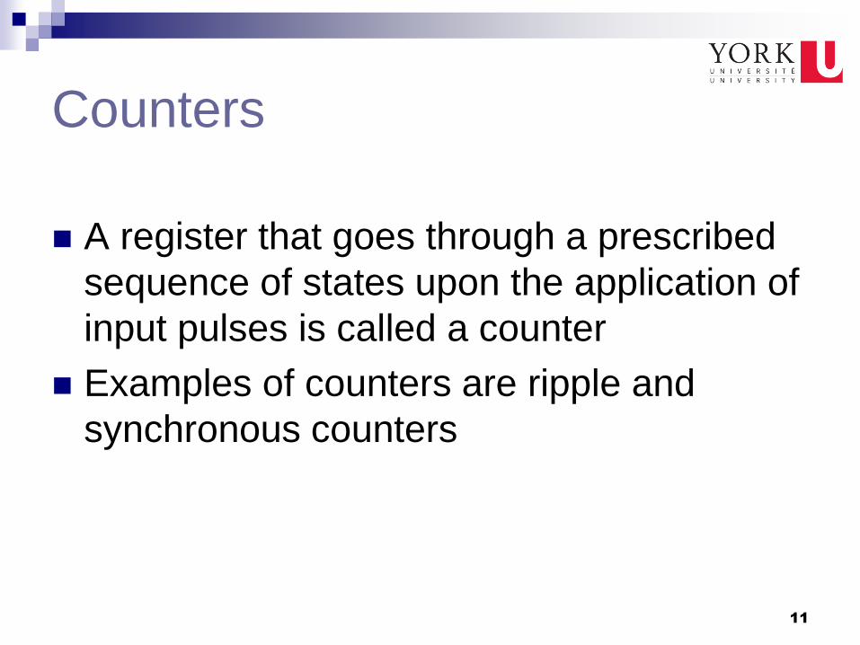
Counters
A register that goes through a prescribed
sequence of states upon the application of
input pulses is called a counter
Examples of counters are ripple and
synchronous counters

12
Ripple Counters Sequence of
States
0
A0
1
0
1
0
A1
0
1
1
0
A2
0
0
0
0
A3
0
0
0
0
0
0
0
1
1
1
1
0
0
1
1
0
1
0
1 0 0 0 1
1 0 0 1
0 1 0 1
1 1 0 1
0 1 1 1
1 1 1 1
0 0 1 1
1 0 1 1 Active-low
Reset
-ve edge
trig. Clock

13
HDL for ripple counter module ripplecounter (A0,A1,A2,A3,Count,Reset);
output A0,A1,A2,A3;
input Count,Reset;
//Instantiate complementing flip-flop
CF F0 (A0,Count,Reset);
CF F1 (A1,A0,Reset);
CF F2 (A2,A1,Reset);
CF F3 (A3,A2,Reset);
endmodule
//Complementing flip-flop with delay
//Input to D flip-flop = Q'
module CF (Q,CLK,Reset);
output Q;
input CLK,Reset;
reg Q;
always @ (negedge CLK or posedge Reset)
if (Reset) Q = 1'b0;
else Q = #2 (~Q); // Delay of 2 time units
endmodule
//Stimulus for testing ripple counter
module testcounter;
reg Count;
reg Reset;
wire A0,A1,A2,A3;
//Instantiate ripple counter
ripplecounter RC (A0,A1,A2,A3,Count,Reset);
always
#5 Count = ~Count;
initial
begin
Count = 1'b0;
Reset = 1'b1;
#4 Reset = 1'b0;
#165 $finish;
end
endmodule
Active-high
Reset
Active-low
Clock

14
Simulation Output
2 ns
15
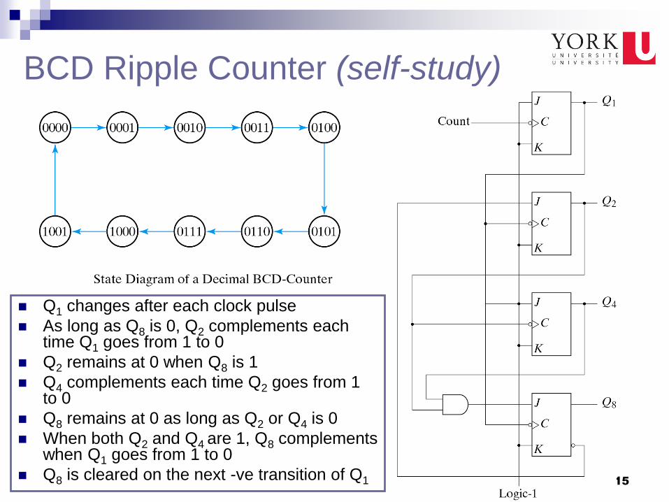
BCD Ripple Counter (self-study)
Q1 changes after each clock pulse
As long as Q8 is 0, Q2 complements each time Q1 goes from 1 to 0
Q2 remains at 0 when Q8 is 1
Q4 complements each time Q2 goes from 1 to 0
Q8 remains at 0 as long as Q2 or Q4 is 0
When both Q2 and Q4 are 1, Q8 complements when Q1 goes from 1 to 0
Q8 is cleared on the next -ve transition of Q1

16
Three-Decade Decimal BCD
Counter

17
Synchronous Counters
All flip flops are driven
by the same clock signal
Sequence of
States
0
A0
1
0
1
0
A1
0
1
1
0
A2
0
0
0
0
A3
0
0
0
0
0
0
0
1
1
1
1
0
0
1
1
0
1
0
1 0 0 0 1
1 0 0 1
0 1 0 1
1 1 0 1
0 1 1 1
1 1 1 1
0 0 1 1
1 0 1 1

18
Counter with Parallel Load
Clear Load Count CLK I0–In-1
n bits
n-bits Binary Counter
with Parallel Load
n bits
A0–An-1 Cout
Load inputs
Clear
X
CLK
1
0
0
Function
Clear to 0
Up-Count
No Change
0
1
1
1
Count Load
X
X
1
0
X
↑
↑
↑
Refer to the textbook for
the circuit diagram

19
HDL for Binary Counter with
Parallel Load
module counter (Count,Load,IN,CLK,Clr,A,CO);
input Count,Load,CLK,Clr;
input [3:0] IN; //Data input
output CO; //Output carry
output [3:0] A; //Data output
reg [3:0] A;
assign CO = Count & ~Load & (A == 4'b1111);
always @ (posedge CLK or negedge Clr)
if (~Clr) A = 4'b0000;
else if (Load) A = IN;
else if (Count) A = A + 1'b1;
else A = A; // no change, default condition
endmodule

20
BCD Counter using Counter
with Parallel Load
A glitch occurs
with an
asynchronous
clear

21
Counter with Unused States
Self Correcting Counter
If it happens to be
in one of the
unused states,
eventually reaches
the normal count
sequences after
one or more clock
pulses
{A,B,C}

22
Generating Timing Signals
k FFs → k states k FFs → 2k states
Assuming
–ve edge-
triggering
Next lecture we will
emphasize why would
this be important

23
Johnson Counter
k FFs → 2k states
T0
T7

24
Corresponding Chapter in
Textbook
Chapter 6 (entire chapter)
25 25
References
Digital Design, M. Morris, Mano
http://bawankule.com/verilogfaq/files/jhld099401.