E/ECE/324 · Web viewE/ECE/TRANS/505 Rev.1/Add.48/Rev.4 13 August 2008 AGREEMENT CONCERNING THE...
797
E/ECE/324 E/ECE/TRANS/ 505 Rev.1/Add.48/ Rev.4 13 August 2008 AGREEMENT CONCERNING THE ADOPTION OF UNIFORM TECHNICAL PRESCRIPTIONS FOR WHEELED VEHICLES, EQUIPMENT AND PARTS WHICH CAN BE FITTED AND/OR BE USED ON WHEELED VEHICLES AND THE CONDITIONS FOR RECIPROCAL RECOGNITION OF APPROVALS GRANTED ON THE BASIS OF THESE PRESCRIPTIONS / (Revision 2, including the amendments which entered into force on 16 October 1995) _________ Addendum 48 : Regulation No. 49 Revision 4 Incorporating all valid text up to: The 03 series of amendments – Date of entry into force: 27 December 2001 The 04 series of amendments - Date of entry into force: 31 January 2003 Supplement 1 to the 04 series of amendments - Date of entry into force: 2 February 2007 Supplement 2 to the 04 series of amendments - Date of entry into force: 12 June 2007 The 05 series of amendments – Date of entry into force: 3 February 2008 / Former title of the Agreement: Agreement Concerning the Adoption of Uniform Conditions of Approval and Reciprocal Recognition of Approval for Motor Vehicle Equipment and Parts, done at Geneva on 20 March 1958. GE.08-25301
Transcript of E/ECE/324 · Web viewE/ECE/TRANS/505 Rev.1/Add.48/Rev.4 13 August 2008 AGREEMENT CONCERNING THE...
E/ECE/324E/ECE/TRANS/505 Rev.1/Add.48/Rev.4
13 August 2008
AGREEMENT
CONCERNING THE ADOPTION OF UNIFORM TECHNICAL PRESCRIPTIONSFOR WHEELED VEHICLES, EQUIPMENT AND PARTS WHICH CAN BE FITTED
AND/OR BE USED ON WHEELED VEHICLES AND THE CONDITIONS FOR RECIPROCAL RECOGNITION OF APPROVALS GRANTED ON THE BASIS OF
THESE PRESCRIPTIONS /
(Revision 2, including the amendments which entered into force on 16 October 1995)_________
Addendum 48: Regulation No. 49
Revision 4
Incorporating all valid text up to:The 03 series of amendments – Date of entry into force: 27 December 2001The 04 series of amendments - Date of entry into force: 31 January 2003Supplement 1 to the 04 series of amendments - Date of entry into force: 2 February 2007Supplement 2 to the 04 series of amendments - Date of entry into force: 12 June 2007The 05 series of amendments – Date of entry into force: 3 February 2008
UNIFORM PROVISIONS CONCERNING THE MEASURES TO BE TAKENAGAINST THE EMISSION OF GASEOUS AND PARTICULATE
POLLUTANTS FROM COMPRESSION-IGNITION ENGINES FOR USE IN VEHICLES, AND THE EMISSION OF GASEOUS POLLUTANTS FROM POSITIVE-IGNITION ENGINES FUELLED WITH NATURAL GAS OR
LIQUEFIED PETROLEUM GASFOR USE IN VEHICLES
_________
UNITED NATIONS
/ Former title of the Agreement:Agreement Concerning the Adoption of Uniform Conditions of Approval and Reciprocal Recognition of Approval for Motor Vehicle Equipment and Parts, done at Geneva on 20 March 1958.
GE.08-25301


E/ECE/324E/ECE/TRANS/505 Rev.1/Add.48/Rev.4
Regulation No. 49page 3
Regulation No. 49
UNIFORM PROVISIONS CONCERNING THE MEASURES TO BE TAKEN AGAINST THE EMISSION OF GASEOUS AND PARTICULATE POLLUTANTS FROM COMPRESSION-
IGNITION ENGINES FOR USE IN VEHICLES, AND THE EMISSION OF GASEOUS POLLUTANTS FROM POSITIVE-IGNITION ENGINES FUELLED WITH NATURAL GAS
OR LIQUEFIED PETROLEUM GAS FOR USE IN VEHICLES
CONTENTS
REGULATION Page
1. Scope .................................................................................................................... 62. Definitions............................................................................................................. 73. Application for approval........................................................................................184. Approval................................................................................................................215. Specifications and tests..........................................................................................306. Installation on the vehicle......................................................................................477. Engine family........................................................................................................478. Conformity of production......................................................................................489. Conformity of in-service vehicles/engines............................................................5310. Penalties for non-conformity of production..........................................................5311. Modification and extension of approval of the approved type..............................5312. Production definitely discontinued........................................................................5413. Transitional provisions..........................................................................................5414. Names and addresses of Technical Services responsible for
conducting approval tests and of Administrative Departments.............................56
Appendix 1 - Procedure for production conformity testing when standard deviation is satisfactory...................................................57
Appendix 2 - Procedure for production conformity testing when standard deviation is unsatisfactory or unavailable.......................59
Appendix 3 - Procedure for production conformity testing at manufacturer's request...................................................................62
Appendix 4 - Determination of system equivalence............................................64
ANNEXES
Annex 1 - Information document..................................................................................66
Appendix 1 - Essential characteristics of the (parent) engine and information concerning the conduct of tests........................67
Appendix 2 - Essential characteristics of the engine family......................76Appendix 3 - Essential characteristics of the engine type within
the family..............................................................................78

E/ECE/324E/ECE/TRANS/505 Rev.1/Add.48/Rev.4
Regulation No. 49page 4
CONTENTS (continued)Page
Appendix 4 - Characteristics of the engine-related vehicle parts............... 85Appendix 5 - OBD-related information..................................................... 86
Annex 2A - Communication concerning the approval or extension or refusal or withdrawal of approval or production definitely discontinued of a compression-ignition (C.I.) engine type or family (Diesel or Ethanol), or a positive-ignition (P.I.) engine type or family (NG or LPG), as a separate technical unit with regard to the emission of pollutants pursuant to Regulation No. 49, 05 series of amendments................................................................................................. 88
Appendix - OBD related information...................................................... 91
Annex 2B - Communication concerning the approval or extension or refusal or withdrawal of approval or production definitely discontinued of a vehicle type with regard to the emission of gaseous and particulate pollutants pursuant to Regulation No. 49................................... 92
Annex 3 - Arrangements of approval marks................................................................. 95
Annex 4A - Test procedure.............................................................................................. 98
Appendix 1 - ESC and ELR test cycles......................................................104Appendix 2 - ETC test cycle......................................................................125Appendix 3 - ETC engine dynamometer schedule.....................................147Appendix 4 - Measurement and sampling procedures...............................187Appendix 5 - Calibration procedure ..........................................................199Appendix 6 – Carbon flow check................................................................219Appendix 7 - Analytical and sampling systems.........................................222
Annex 4B - Test procedure for compression-ignition (C.I.) engines and positive-ignition (P.I.) engines fuelled with natural gas (N.G.) or liquefied petroleum gas (LPG) incorporating the world-wide harmonized heavy-duty certification (WHDC, global technical regulation (gtr) No. 4)..................................................................................260
Appendix 1 - WHTC engine dynamometer schedule.................................344Appendix 2 - Diesel reference fuel.............................................................357Appendix 3 - Measurement equipment......................................................358Appendix 4 - Determination of system equivalence..................................375Appendix 5 - Carbon flow check................................................................377Appendix 6 - Example of calculation procedure........................................380

E/ECE/324E/ECE/TRANS/505 Rev.1/Add.48/Rev.4
Regulation No. 49page 5
CONTENTS (continued)Page
Annex 5 - Technical characteristics of reference fuel prescribed for approval tests and to verify the conformity of production...........................384
Annex 6 - Example of calculation procedure................................................................391
Annex 7 - Procedures for conducting the test for durability of emission control systems.............................................................................................414
Annex 8 - Conformity of in-service vehicles/engines..................................................422
Annex 9A - On-board diagnostic systems (OBD)...........................................................431
Appendix - On-board diagnostic (OBD) system approval tests..............445
Annex 9B - Technical requirements for on-board diagnostic systems (OBD) for diesel engines of road vehicles (WWH-OBD, gtr No. 5)............................451
Appendix 1 - Approval of installation of OBD systems............................496Appendix 2 - Malfunctions - Illustration of the DTC status –
Illustation of the MI and counters activation schemes.........497Appendix 3 - Monitoring requirements......................................................502Appendix 4 - Technical compliance report................................................507Appendix 5 - Freeze frame and data stream information...........................516Appendix 6 - Reference standard documents.............................................518Appendix 7 - Documentation regarding OBD related information ...........519

E/ECE/324E/ECE/TRANS/505 Rev.1/Add.48/Rev.4
Regulation No. 49page 6
1. SCOPE
1.1. This Regulation applies to vehicles of categories M and N 1/ and their engines, as shown in table A, with regard to the tests foreseen for these engines in table B. It also applies to the installation of these engines on vehicles.
Table A: APPLICABILITYVehicle
category 1/Maximum
massPositive-ignition engines Compression-ignition engines
Petrol NG (a) LPG (b) Diesel Ethanol
M1≤ 3.5 t - - - - -> 3.5 t - R49 R49 R49 R49
M2 - - R49 R49 R49 or R83 (c) (d) R49M3 - - R49 R49 R49 R49N1 - - R49 or R83 (d) R49 or R83 (d) R49 or R83 (d) R49N2 - - R49 R49 R49 or R83 (c) (d) R49N3 - - R49 R49 R49 R49(a) Natural Gas.(b) Liquefied Petroleum Gas.(c) Regulation No. 83 applies only for vehicles with a reference mass ≤ 2,840 kg as an
extension of an approval given for a vehicle of categories M1 or N1. 1/(d) "R49 or R83" means that manufacturers can obtain type approval according to this
Regulation or to Regulation No. 83, see paragraph 1.2.
Table B: REQUIREMENTSPositive-ignition engines Compression-ignition engines
Petrol NG LPG Diesel EthanolGaseous pollutants - Yes Yes Yes YesParticulates - Yes (a) Yes (a) Yes YesSmoke - - - Yes YesDurability - Yes Yes Yes YesIn-service-conformity - Yes Yes Yes YesOBD - Yes (b) Yes (b) Yes Yes
(a) Only applicable to stage C in Table 2 of paragraph 5.2.1.(b) Application dates according to paragraph 5.4.2.
1.2. Equivalent approvals
The following do not need to be approved according to this Regulation, if they are part of a vehicle approved according to Regulation No. 83:(a) compression-ignition engines to be mounted in vehicles of categories N1, N2
and M2 1/ fuelled with diesel;
1/ As defined in Annex 7 to the Consolidated Resolution on the Construction of Vehicles (R.E.3), (document TRANS/WP.29/78/Rev.1/Amend.2, as last amended by Amend.4).

E/ECE/324E/ECE/TRANS/505 Rev.1/Add.48/Rev.4
Regulation No. 49page 7
(b) positive-ignition engines fuelled with natural gas (NG) or liquefied petroleum gas (LPG) to be mounted in vehicles of category N1. 1/
(c) vehicles of categories N1, N2 and M2 1/ fitted with compression - ignition engines fuelled with diesel and vehicles of category N1 1/ fitted with positive-ignition engines fuelled with natural gas (NG) or liquefied petroleum gas (LPG).
2. DEFINITIONS
2.1. For the purposes of this Regulation, the following definitions shall apply:
2.1.1. "approval of an engine (engine family)" means the approval of an engine type (engine family) with regard to the level of the emission of gaseous and particulate pollutants, smoke and the on-board diagnostic (OBD) system;
2.1.2. "approval of a vehicle" means the approval of vehicle type with regard to the level of the emission of gaseous and particulate pollutants and smoke by its engine as well as the on-board diagnostic (OBD) system and the engine installation on the vehicle;
2.1.3. "rated speed" means the maximum full load engine speed allowed by the governor, or, if such a governor is not present, the speed at which the maximum power is obtained from the engine, as specified by the manufacturer in paragraph 2. of Appendix 2 to Annex 1.
2.1.4. "vehicle type" means a category of power driven vehicles which do not differ in such essential respects as the vehicle and engine characteristics as specified in Annex 1 of this Regulation.
2.1.5. "auxiliary emission control strategy (AECS)" means an emission control strategy that becomes active or that modifies the base emission control strategy for a specific purpose or purposes and in response to a specific set of ambient and/or operating conditions, e.g. vehicle speed, engine speed, gear used, intake temperature, or intake pressure;
2.1.6. "base emission control strategy (BECS)" means an emission control strategy that is active throughout the speed and load operating range of the engine unless an AECS is activated. Examples for BECS are, but are not limited to:(a) engine timing map;(b) EGR map;(c) SCR catalyst reagent dosing map;
2.1.7. "combined deNOx- particulate filter" means an exhaust aftertreatment system designed to concurrently reduce emissions of oxides of nitrogen (NOx) and particulate pollutants (PT);

E/ECE/324E/ECE/TRANS/505 Rev.1/Add.48/Rev.4
Regulation No. 49page 8
2.1.8. "continuous regeneration" means the regeneration process of an exhaust aftertreatment system that occurs either permanently or at least once per ETC test. Such a regeneration process will not require a special test procedure;
2.1.9. "control area" means the area between the engine speeds A and C and between 25 to 100 per cent load;
2.1.10. "declared maximum power (Pmax)" means the maximum power in EC kW (net power) as declared by the manufacturer in his application for approval;
2.1.11. "defeat strategy" means:(a) an AECS that reduces the effectiveness of the emission control relative to the
BECS under conditions that may reasonably be expected to be encountered in normal vehicle operation and use;
(b) a BECS that discriminates between operation on a standardized approval test and other operations and provides a lesser level of emission control under conditions not substantially included in the applicable approval test procedures, or;
(c) an OBD or an emission control monitoring strategy that discriminates between operation on a standardized approval test and other operations and provides a lower level of monitoring capability (timely and accurately) under conditions not substantially included in the applicable approval test procedures;
2.1.12. "deNOx system" means an exhaust aftertreatment system designed to reduce emissions of oxides of nitrogen (NOx) (e.g. there are presently passive and active lean NOx catalysts, NOx adsorbers and selective catalytic reduction (SCR) systems);
2.1.13. "delay time" means the time between the change of the component to be measured at the reference point and a system response of 10 per cent of the final reading (t10). For the gaseous components, this is basically the transport time of the measured component from the sampling probe to the detector. For the delay time, the sampling probe is defined as the reference point;
2.1.14. "diesel engine" means an engine which works on the compression-ignition principle;
2.1.15. "ELR test" means a test cycle consisting of a sequence of load steps at constant engine speeds to be applied in accordance with paragraph 5.2.;
2.1.16. "ESC test" means a test cycle consisting of 13 steady state modes to be applied in accordance with paragraph 5.2.;
2.1.17. "ETC test" means a test cycle consisting of 1800 second-by-second transient modes to be applied in accordance with paragraph 5.2.;
2.1.18. "element of design" means in respect of a vehicle or engine,

E/ECE/324E/ECE/TRANS/505 Rev.1/Add.48/Rev.4
Regulation No. 49page 9
(a) any control system, including computer software, electronic control systems and computer logic;
(b) any control system calibrations;(c) the result of systems interaction, or;(d) any hardware items;
2.1.19. "emissions-related defect" means a deficiency or deviation from normal production tolerances in design, materials or workmanship in a device, system or assembly that affects any parameter, specification or component belonging to the emission control system. A missing component may be considered to be an "emissions-related defect";
2.1.20. "emission control strategy (ECS)" means an element or set of elements of design that is incorporated into the overall design of an engine system or vehicle for the purposes of controlling exhaust emissions that includes one BECS and one set of AECS;
2.1.21. "emission control system" means the exhaust aftertreatment system, the electronic management controller(s) of the engine system and any emission-related component of the engine system in the exhaust which supplies an input to or receives an output from this(these) controller(s), and when applicable the communication interface (hardware and messages) between the engine system electronic control unit(s) (EECU) and any other power train or vehicle control unit with respect to emissions management;
2.1.22. "emission control monitoring system" means the system that ensures correct operation of the NOx control measures implemented in the engine system according to the requirements of paragraph 5.5.
2.1.23. "emission default mode" means an AECS activated in the case of a malfunction of the ECS detected by the OBD system that results in the MI being activated and that does not require an input from the failed component or system;
2.1.24. "engine-aftertreatment system family" means, for testing over a service accumulation schedule to establish deterioration factors according to Annex 7 to this Regulation and for checking the conformity of in-service vehicles/engines according to Annex 8 to this Regulation, a manufacturer's grouping of engines that comply with the definition of engine family but which are further grouped into engines utilising a similar exhaust after-treatment system;
2.1.25. "engine system" means the engine, the emission control system and the communication interface (hardware and messages) between the engine system electronic control unit(s) (EECU) and any other powertrain or vehicle control unit;

E/ECE/324E/ECE/TRANS/505 Rev.1/Add.48/Rev.4
Regulation No. 49page 10
2.1.26. "engine family" means a manufacturer's grouping of engine systems which, through their design as defined in paragraph 7. of this Regulation, have similar exhaust emission characteristics; all members of the family shall comply with the applicable emission limit values;
2.1.27. "engine operating speed range" means the engine speed range, most frequently used during engine field operation, which lies between the low and high speeds, as set out in Appendix 1 to Annex 4A to this Regulation;
2.1.28. "engine speeds A, B and C" means the test speeds within the engine operating speed range to be used for the ESC test and the ELR test, as set out in Appendix 1 to Annex 4A to this Regulation;
2.1.29. "engine setting" means a specific engine/vehicle configuration that includes the emission control strategy (ECS), one single engine performance rating (the approved full-load curve) and, if used, one set of torque limiters;
2.1.30. "engine type" means a category of engines which do not differ in such essential respects as engine characteristics as described in Annex 1 to this Regulation;
2.1.31. "exhaust aftertreatment system" means a catalyst (oxidation or 3-way), particulate filter, deNOx system, combined deNOx-particulate filter or any other emission-reducing device that is installed downstream of the engine. This definition excludes exhaust gas recirculation, which, where fitted, is considered an integral part of the engine system;
2.1.32. "gas engine" means a positive-ignition engine which is fuelled with natural gas (NG) or liquefied petroleum gas (LPG);
2.1.33. "gaseous pollutants" means carbon monoxide, hydrocarbons (assuming a ratio of CH1.85 for diesel, CH2.525 for LPG and CH2.93 for NG (NMHC) and an assumed molecule CH3O0.5 for ethanol-fuelled diesel engines), methane (assuming a ratio of CH4 for NG) and oxides of nitrogen, the last-named being expressed in nitrogen dioxide (NO2) equivalent;
2.1.34. "high speed (nhi)" means the highest engine speed where 70 per cent of the declared maximum power occurs;
2.1.35. "low speed (nlo)" means the lowest engine speed where 50 per cent of the declared maximum power occurs;

E/ECE/324E/ECE/TRANS/505 Rev.1/Add.48/Rev.4
Regulation No. 49page 11
2.1.36. "major functional failure" 2/ means a permanent or temporary malfunction of any exhaust aftertreatment system that is expected to result in an immediate or delayed increase of the gaseous or particulate emissions of the engine system and which cannot be properly estimated by the OBD system;
2.1.37. "malfunction" means:(a) any deterioration or failure, including electrical failures, of the emission control
system, that would result in emissions exceeding the OBD threshold limits or, when applicable, in failing to reach the range of functional performance of the exhaust aftertreatment system where the emission of any regulated pollutant would exceed the OBD threshold limits;
(b) any case where the OBD system is not able to fulfil the monitoring requirements of this Regulation.
A manufacturer may nevertheless consider a deterioration or failure that would result in emissions not exceeding the OBD threshold limits as a malfunction;
2.1.38. "malfunction indicator (MI)" means a visual indicator that clearly informs the driver of the vehicle in the event of a malfunction in the sense of this Regulation;
2.1.39. "multi-setting engine" means an engine containing more than one engine setting;
2.1.40. "NG gas range" means one of the H or L range as defined in European Standard EN 437, dated November 1993;
2.1.41. "net power" means the power in kW obtained on the test bench at the end of the crankshaft, or its equivalent, measured in accordance with the method of measuring power as set out in Regulation No. 85;
2.1.42. "OBD" means an on-board diagnostic system for emission control, which has the capability of detecting the occurrence of a malfunction and of identifying the likely area of malfunction by means of fault codes stored in computer memory;
2.1.43. "OBD-engine family" means, for approval of the OBD system according to the requirements of Annex 9A to this Regulation, a manufacturer's grouping of engine systems having common OBD system design parameters according to paragraph 7.3. of this Regulation;
2.1.44. "opacimeter" means an instrument designed to measure the opacity of smoke particles by means of the light extinction principle;
2/ Paragraph 5.4.1. of this Regulation provides for the monitoring for major functional failure instead of monitoring for the degradation or the loss of catalytic/filtering efficiency of an exhaust aftertreatment system. Examples of major functional failure are given in paragraphs 3.2.3.2. and 3.2.3.3. of Annex 9A to this Regulation.

E/ECE/324E/ECE/TRANS/505 Rev.1/Add.48/Rev.4
Regulation No. 49page 12
2.1.45. "parent engine" means an engine selected from an engine family in such a way that its emissions characteristics will be representative for that engine family;
2.1.46. "particulate aftertreatment device" means an exhaust aftertreatment system designed to reduce emissions of particulate pollutants (PT) through a mechanical, aerodynamic, diffusional or inertial separation;
2.1.47. "particulate pollutants" means any material collected on a specified filter medium after diluting the exhaust with clean filtered air so that the temperature does not exceed 325 K (52 °C);
2.1.48. "per cent load" means the fraction of the maximum available torque at an engine speed;
2.1.49. "periodic regeneration" means the regeneration process of an emission control device that occurs periodically in less than 100 hours of normal engine operation. During cycles where regeneration occurs, emission standards can be exceeded.
2.1.50. "power take-off unit" means an engine-driven output device for the purposes of powering auxiliary, vehicle mounted, equipment;
2.1.51. "reagent" means any medium that is stored on-board the vehicle in a tank and provided to the exhaust aftertreatment system (if required) upon request of the emission control system;
2.1.52. "recalibration" means a fine tuning of an NG engine in order to provide the same performance (power, fuel consumption) in a different range of natural gas;
2.1.53. "reference speed (nref)" means the 100 per cent speed value to be used for denormalizing the relative speed values of the ETC test, as set out in Appendix 2 to Annex 4A to this Regulation;
2.1.54. "response time" means the difference in time between a rapid change of the component to be measured at the reference point and the appropriate change in the response of the measuring system whereby the change of the measured component is at least 60 per cent FS and takes place in less than 0.1 second. The system response time (t90) consists of the delay time to the system and of the rise time of the system (see also ISO 16183);
2.1.55. "rise time" means the time between the 10 per cent and 90 per cent response of the final reading (t90 – t10). This is the instrument response after the component to be measured has reached the instrument. For the rise time, the sampling probe is defined as the reference point;

E/ECE/324E/ECE/TRANS/505 Rev.1/Add.48/Rev.4
Regulation No. 49page 13
2.1.56. "self adaptability" means any engine device allowing the air/fuel ratio to be kept constant;
2.1.57. "smoke" means particles suspended in the exhaust stream of a diesel engine which absorb, reflect, or refract light;
2.1.58. "test cycle" means a sequence of test points each with a defined speed and torque to be followed by the engine under steady state (ESC test) or transient operating conditions (ETC, ELR test);
2.1.59. "torque limiter" means a device that temporarily limits the maximum torque of the engine;
2.1.60. "transformation time" means the time between the change of the component to be measured at the sampling probe and a system response of 50 per cent of the final reading (t50). The transformation time is used for the signal alignment of different measurement instruments;
2.1.61. "useful life" means, for vehicles and engines that are approved to either row B1, row B2 or row C of the table given in paragraph 5.2.1. of this Regulation, the relevant period of distance and/or time that is defined in paragraph 5.3. (durability of emission control systems) of this Regulation over which compliance with the relevant gaseous, particulate and smoke emission limits has to be assured as part of the approval;
2.1.62. "Wobbe index (lower Wl; or upper Wu)" means the ratio of the corresponding calorific value of a gas per unit volume and the square root of its relative density under the same reference conditions:
2.1.63. "λ-shift factor (Sλ)" means an expression that describes the required flexibility of the engine management system regarding a change of the excess-air ratio λ if the engine is fuelled with a gas composition different from pure methane (see Annex 6 for the calculation of Sλ).
2.2. Symbols, abbreviations and international standards
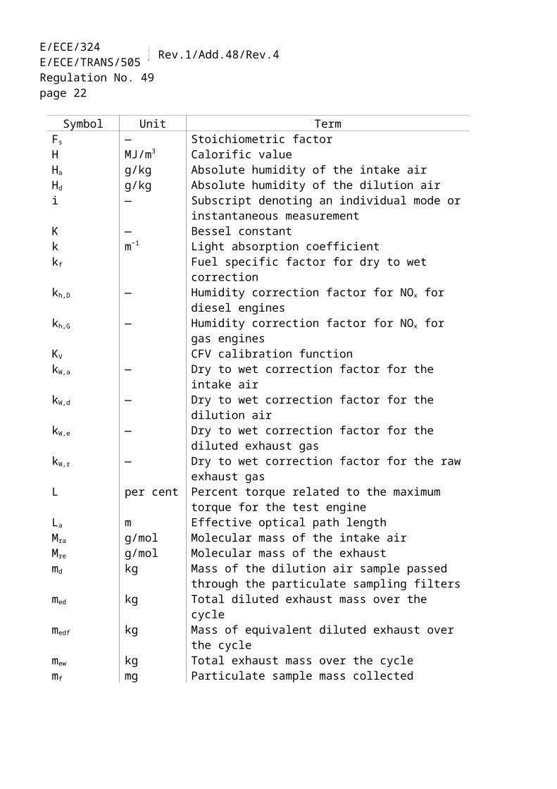
2.2.1. Symbols for test parameters:
Symbol Unit TermAp m2 Cross sectional area of the isokinetic sampling probeAe m2 Cross sectional area of the exhaust pipec ppm/vol.
per centConcentration
Cd — Discharge coefficient of SSV-CVS

E/ECE/324E/ECE/TRANS/505 Rev.1/Add.48/Rev.4
Regulation No. 49page 14
Symbol Unit TermC1 — Carbon 1 equivalent hydrocarbond m DiameterD0 m3/s Intercept of PDP calibration functionD — Dilution factorD — Bessel function constantE — Bessel function constantEE — Ethane efficiencyEM — Methane efficiencyEZ g/kWh Interpolated NOx emission of the control pointf 1/s Frequencyfa — Laboratory atmospheric factorfc s−1 Bessel filter cut-off frequencyFs — Stoichiometric factorH MJ/m3 Calorific valueHa g/kg Absolute humidity of the intake airHd g/kg Absolute humidity of the dilution airi — Subscript denoting an individual mode or instantaneous
measurementK — Bessel constantk m−1 Light absorption coefficientkf Fuel specific factor for dry to wet correctionkh,D — Humidity correction factor for NOx for diesel engineskh,G — Humidity correction factor for NOx for gas enginesKV CFV calibration functionkW,a — Dry to wet correction factor for the intake airkW,d — Dry to wet correction factor for the dilution airkW,e — Dry to wet correction factor for the diluted exhaust gaskW,r — Dry to wet correction factor for the raw exhaust gasL per cent Percent torque related to the maximum torque for the test
engineLa m Effective optical path lengthMra g/mol Molecular mass of the intake airMre g/mol Molecular mass of the exhaustmd kg Mass of the dilution air sample passed through the
particulate sampling filtersmed kg Total diluted exhaust mass over the cyclemedf kg Mass of equivalent diluted exhaust over the cyclemew kg Total exhaust mass over the cyclemf mg Particulate sample mass collectedmf,d mg Particulate sample mass of the dilution air collectedmgas g/h or g Gaseous emissions mass flow (rate)mse kg Sample mass over the cycle
E/ECE/324E/ECE/TRANS/505 Rev.1/Add.48/Rev.4
Regulation No. 49page 15
Symbol Unit Termmsep kg Mass of the diluted exhaust sample passed through the
particulate sampling filtersmset kg Mass of the double diluted exhaust sample passed through
the particulate sampling filtersmssd kg Mass of secondary dilution airN per cent OpacityNP — Total revolutions of PDP over the cycleNP,i — Revolutions of PDP during a time intervaln min−1 Engine speednp s−1 PDP speednhi min−1 High engine speednlo min−1 Low engine speednref min−1 Reference engine speed for ETC testpa kPa Saturation vapour pressure of the engine intake airpb kPa Total atmospheric pressurepd kPa Saturation vapour pressure of the dilution airpp kPa Absolute pressurepr kPa Water vapour pressure after cooling bathps kPa Dry atmospheric pressurep1 kPa Pressure depression at pump inletP(a) kW Power absorbed by auxiliaries to be fitted for testP(b) kW Power absorbed by auxiliaries to be removed for testP(n) kW Net power non-correctedP(m) kW Power measured on test bedq
mawkg/h or kg/s Intake air mass flow rate on wet basis
qmad
kg/h or kg/s Intake air mass flow rate on dry basisq
mdwkg/h or kg/s Dilution air mass flow rate on wet basis
qmdew
kg/h or kg/s Diluted exhaust gas mass flow rate on wet basisq
mdew,ikg/s Instantaneous CVS flow rate mass on wet basis
qmedf
kg/h or kg/s Equivalent diluted exhaust gas mass flow rate on wet basisq
mewkg/h or kg/s Exhaust gas mass flow rate on wet basis
qmf
kg/h or kg/s Fuel mass flow rateq
mpkg/h or kg/s Particulate sample mass flow rate
qvs
dm³/min Sample flow rate into analyzer benchq
vtcm³/min Tracer gas flow rate
Ω — Bessel constantQs m3/s PDP/CFV-CVS volume flow rateQSSV m3/s SSV-CVS volume flow ratera — Ratio of cross sectional areas of isokinetic probe and
exhaust piperd — Dilution ratiorD — Diameter ratio of SSV-CVS
E/ECE/324E/ECE/TRANS/505 Rev.1/Add.48/Rev.4
Regulation No. 49page 16
Symbol Unit Termrp — Pressure ratio of SSV-CVSrs — Sample ratioRf — FID response factorρ kg/m3 densityS kW Dynamometer settingS i m−1 Instantaneous smoke valueSλ — λ-shift factorT K Absolute temperatureTa K Absolute temperature of the intake airt s Measuring timete s Electrical response timetf s Filter response time for Bessel functiontp s Physical response timeΔt s Time interval between successive smoke data (= 1/sampling
rate)Δti s Time interval for instantaneous CVS flowτ per cent Smoke transmittanceu - Ratio between densities of gas component and exhaust gasV0 m3/rev PDP gas volume pumped per revolutionVs l System volume of analyzer benchW — Wobbe indexWact kWh Actual cycle work of ETCWref kWh Reference cycle work of ETCWf — Weighting factorWfe — Effective weighting factorX0 m3/rev Calibration function of PDP volume flow rateYi m−1 1 s Bessel averaged smoke value
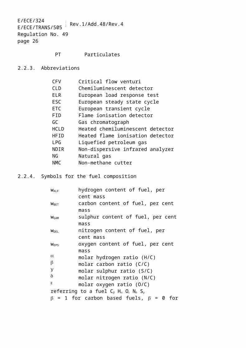
2.2.2. Symbols for chemical components
CH4 MethaneC2H6 EthaneC2H5OH EthanolC3H8 PropaneCO Carbon monoxideDOP Di-octylphtalateCO2 Carbon dioxideHC HydrocarbonsNMHC Non-methane hydrocarbonsNOx Oxides of nitrogenNO Nitric oxideNO2 Nitrogen dioxidePT Particulates
E/ECE/324E/ECE/TRANS/505 Rev.1/Add.48/Rev.4
Regulation No. 49page 17
2.2.3. Abbreviations
CFV Critical flow venturiCLD Chemiluminescent detectorELR European load response testESC European steady state cycleETC European transient cycleFID Flame ionisation detectorGC Gas chromatographHCLD Heated chemiluminescent detectorHFID Heated flame ionisation detectorLPG Liquefied petroleum gasNDIR Non-dispersive infrared analyzerNG Natural gasNMC Non-methane cutter
2.2.4. Symbols for the fuel composition
wALF hydrogen content of fuel, per cent masswBET carbon content of fuel, per cent masswGAM sulphur content of fuel, per cent masswDEL nitrogen content of fuel, per cent masswEPS oxygen content of fuel, per cent mass molar hydrogen ratio (H/C) molar carbon ratio (C/C) molar sulphur ratio (S/C) molar nitrogen ratio (N/C) molar oxygen ratio (O/C)referring to a fuel C H O N S
= 1 for carbon based fuels, = 0 for hydrogen fuel
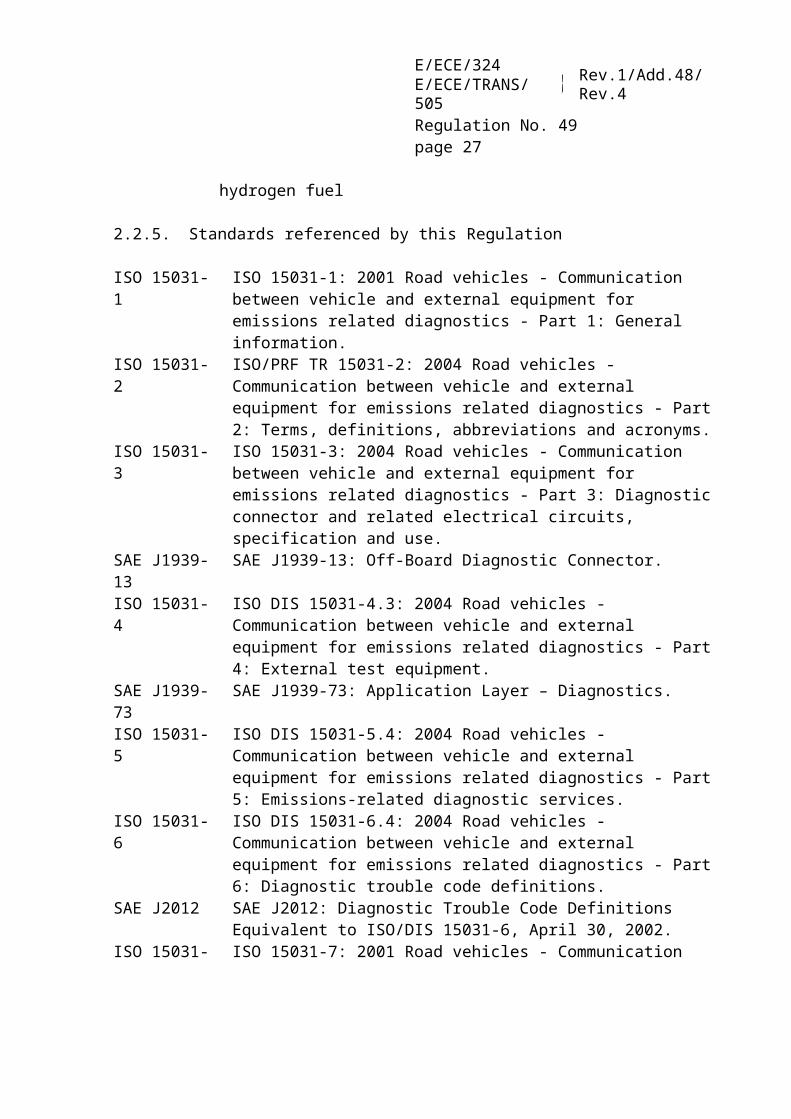
2.2.5. Standards referenced by this Regulation
ISO 15031-1 ISO 15031-1: 2001 Road vehicles - Communication between vehicle and external equipment for emissions related diagnostics - Part 1: General information.
ISO 15031-2 ISO/PRF TR 15031-2: 2004 Road vehicles - Communication between vehicle and external equipment for emissions related diagnostics - Part 2: Terms, definitions, abbreviations and acronyms.
ISO 15031-3 ISO 15031-3: 2004 Road vehicles - Communication between vehicle and external equipment for emissions related diagnostics - Part 3: Diagnostic connector and related electrical circuits, specification and use.
SAE J1939-13 SAE J1939-13: Off-Board Diagnostic Connector.

E/ECE/324E/ECE/TRANS/505 Rev.1/Add.48/Rev.4
Regulation No. 49page 18
ISO 15031-4 ISO DIS 15031-4.3: 2004 Road vehicles - Communication between vehicle and external equipment for emissions related diagnostics - Part 4: External test equipment.
SAE J1939-73 SAE J1939-73: Application Layer – Diagnostics.ISO 15031-5 ISO DIS 15031-5.4: 2004 Road vehicles - Communication between vehicle
and external equipment for emissions related diagnostics - Part 5: Emissions-related diagnostic services.
ISO 15031-6 ISO DIS 15031-6.4: 2004 Road vehicles - Communication between vehicle and external equipment for emissions related diagnostics - Part 6: Diagnostic trouble code definitions.
SAE J2012 SAE J2012: Diagnostic Trouble Code Definitions Equivalent to ISO/DIS 15031-6, April 30, 2002.
ISO 15031-7 ISO 15031-7: 2001 Road vehicles - Communication between vehicle and external equipment for emissions related diagnostics - Part 7: Data link security.
SAE J2186 SAE J2186: E/E Data Link Security, dated October 1996.ISO 15765-4 ISO 15765-4: 2001 Road vehicles - Diagnostics on Controller Area
Network (CAN) - Part 4: Requirements for emissions-related systems.SAE J1939 SAE J1939: Recommended Practice for a Serial Control and
Communications Vehicle Network.ISO 16185 ISO 16185: 2000 Road vehicles – engine family for homologation. ISO 2575 ISO 2575: 2000 Road vehicles – Symbols for controls, indicators and tell-
tales.ISO 16183 ISO 16183: 2002 Heavy duty engines - Measurement of gaseous emissions
from raw exhaust gas and of particulate emissions using partial flow dilution systems under transient test conditions.
3. APPLICATION FOR APPROVAL
3.1. Application for approval for a type of engine or engine family as a separate technical unit
3.1.1. The application for approval of an engine type or engine family with regard to the requirements listed in table B, paragraph 1.1. shall be submitted by the engine manufacturer or by a duly accredited representative.
Should the application concern an engine equipped with an on-board diagnostic (OBD) system, the requirements of paragraph 3.4. shall be fulfilled.
3.1.2. It shall be accompanied by the undermentioned documents in triplicate and the following particulars:
3.1.2.1. A description of the engine type or engine family, if applicable, comprising the particulars referred to in Annex 1 to this Regulation.

E/ECE/324E/ECE/TRANS/505 Rev.1/Add.48/Rev.4
Regulation No. 49page 19
3.1.3. An engine conforming to the "engine type" or "parent engine" characteristics described in Annex 1 shall be submitted to the Technical Service responsible for conducting the approval tests defined in paragraph 5.
3.2. Application for approval for a vehicle type in respect of its engine
3.2.1. The application for approval of a vehicle type with regard to the requirements for its engine, or engine family, listed in table B of paragraph 1.1. and the installation of the engine on the vehicle shall be submitted by the vehicle manufacturer or by a duly accredited representative.
Should the application concern an engine equipped with an on-board diagnostic (OBD) system, the requirements of paragraph 3.4. shall be fulfilled.
3.2.2. It shall be accompanied by the below-mentioned documents in triplicate and the following particulars:
3.2.2.1. A description of the vehicle type, of the engine-related vehicle parts and of the engine type or engine family, if applicable, comprising the particulars referred to in Annex 1 to this Regulation.
3.2.3. The manufacturer shall provide a description of the malfunction indicator (MI) used by the OBD system to signal the presence of a fault to a driver of the vehicle.
The manufacturer shall provide a description of the indicator and warning mode used to signal the lack of required reagent to a driver of the vehicle.
3.2.4. A vehicle conforming to the "vehicle type" characteristics defined in Annex 1 shall be submitted to the Technical Service responsible for conducting the approval tests defined in paragraphs 5 and 6.
3.3. Application for approval for a vehicle type with an approved engine
3.3.1. The application for approval of a vehicle type with regard to the installation of an approved engine on the vehicle shall be submitted by the vehicle manufacturer or by a duly accredited representative.
3.3.2. It shall be accompanied by the undermentioned documents in triplicate and the following particulars:
3.3.2.1. a description of the vehicle type and of engine-related vehicle parts comprising the particulars referred to in Annex 1, as applicable, and a copy of the approval communication form (Annex 2A) for the engine or engine family, if applicable, as a separate technical unit which is installed in the vehicle type.

E/ECE/324E/ECE/TRANS/505 Rev.1/Add.48/Rev.4
Regulation No. 49page 20
3.3.3. The manufacturer shall provide a description of the malfunction indicator (MI) used by the OBD system to signal the presence of a fault to a driver of the vehicle.
The manufacturer shall provide a description of the indicator and warning mode used to signal the lack of required reagent to a driver of the vehicle.
3.3.4. A vehicle conforming to the "vehicle type" characteristics defined in Annex 1 shall be submitted to the Technical Service responsible for conducting the approval tests defined in paragraph 6.
3.4. On-board diagnostic systems
3.4.1. The application for approval of a vehicle or an engine equipped with an on-board diagnostic (OBD) system shall be accompanied by the information required in paragraph 9. of Annex 1 (description of the parent engine) and/or paragraph 6. of Appendix 2 to Annex 1 (description of an engine type within the family) together with:
3.4.1.1. Detailed written information fully describing the functional operation characteristics of the OBD system, including a listing of all relevant parts of the engine's emission control system, i.e. sensors, actuators and components, that are monitored by the OBD system;
3.4.1.2. Where applicable, a declaration by the manufacturer of the parameters that are used as a basis for major functional failure monitoring and, in addition:
3.4.1.2.1. The manufacturer shall provide the Technical Service with a description of potential failures within the emission control system that will have an effect on emissions. This information shall be subject to discussion and agreement between the Technical Service and the vehicle manufacturer.
3.4.1.3. Where applicable, a description of the communication interface (hardware and messages) between the engine electronic control unit (EECU) and any other powertrain or vehicle control unit when the exchanged information has an influence on the correct functioning of the emission control system.
3.4.1.4. Where appropriate, copies of other approvals with the relevant data to enable extensions of approvals.
3.4.1.5. If applicable, the particulars of the engine family as referred to in paragraph 7. of this Regulation.
3.4.1.6. The manufacturer shall describe provisions taken to prevent tampering with and modification of the EECU or any interface parameter considered in paragraph 3.4.1.3.

E/ECE/324E/ECE/TRANS/505 Rev.1/Add.48/Rev.4
Regulation No. 49page 21
4. APPROVAL
4.1. Granting of a universal fuel approval
A universal fuel approval is granted subject to the following requirements.
4.1.1. In the case of diesel or ethanol fuel the parent engine meets the requirements of this Regulation on the reference fuel specified in Annex 5.
4.1.2. In the case of natural gas the parent engine should demonstrate its capability to adapt to any fuel composition that may occur across the market. In the case of natural gas there are generally two types of fuel, high calorific fuel (H-gas) and low calorific fuel (L-gas), but with a significant spread within both ranges; they differ significantly in their energy content expressed by the Wobbe Index and in their λ-shift factor (Sλ). The formulae for the calculation of the Wobbe index and Sλ are given in paragraph 2.1.62. and in Annex 6. Natural gases with a λ-shift factor between 0.89 and 1.08 (0.89 ≤ Sλ ≤ 1.08) are considered to belong to H-range, while natural gases with a λ-shift factor between 1.08 and 1.19 (1.08 ≤ Sλ ≤ 1.19) are considered to belong to L-range. The composition of the reference fuels reflects the extreme variations of Sλ.
The parent engine shall meet the requirements of this Regulation on the reference fuels GR (fuel 1) and G25 (fuel 2), as specified in Annex 5, without any readjustment to the fuelling between the two tests. However, one adaptation run over one ETC cycle without measurement is permitted after the change of the fuel. Before testing, the parent engine shall be run-in using the procedure given in paragraph 3. of Appendix 2 to Annex 4A.
4.1.2.1. On the manufacturer's request the engine may be tested on a third fuel (fuel 3) if the λ-shift factor (Sλ) lies between 0.89 (i.e. the lower range of GR) and 1.19 (i.e. the upper range of G25), for example when fuel 3 is a market fuel. The results of this test may be used as a basis for the evaluation of the conformity of the production.
4.1.3. In the case of an engine fuelled with natural gas which is self-adaptive for the range of H-gases on the one hand and the range of L-gases on the other hand, and which switches between the H-range and the L-range by means of a switch, the parent engine shall be tested on the relevant reference fuel as specified in Annex 5 for each range, at each position of the switch. The fuels are GR (fuel 1) and G23 (fuel 3) for the H-range of gases and G25 (fuel 2) and G23 (fuel 3) for the L-range of gases. The parent engine shall meet the requirements of this Regulation at both positions of the switch without any readjustment to the fuelling between the two tests at each position of the switch. However, one adaptation run over one ETC cycle without measurement is permitted after the change of the fuel. Before testing, the parent engine shall be run-in using the procedure given in paragraph 3. of Appendix 2 to Annex 4A.
E/ECE/324E/ECE/TRANS/505 Rev.1/Add.48/Rev.4
Regulation No. 49page 22
4.1.3.1. At the manufacturer's request the engine may be tested on a third fuel instead of G23
(fuel 3) if the λ-shift factor (Sλ) lies between 0.89 (i.e. the lower range of GR) and 1.19 (i.e. the upper range of G25), for example when fuel 3 is a market fuel. The results of this test may be used as a basis for the evaluation of the conformity of the production.
4.1.4. In the case of natural gas engines, the ratio of the emission results "r" shall be determined for each pollutant as follows:
1 fuel referenceon result emission 2 fuel referenceon result emission r
or,
3 fuel referenceon result emission 2 fuel referenceon result emission ra
and,
3 fuel referenceon result emission 1 fuel referenceon result emission rb
4.1.5. In the case of LPG the parent engine should demonstrate its capability to adapt to any fuel composition that may occur across the market. In the case of LPG there are variations in C3/C4 composition. These variations are reflected in the reference fuels. The parent engine should meet the emission requirements on the reference fuels A and B as specified in Annex 5 without any readjustment to the fuelling between the two tests. However, one adaptation run over one ETC cycle without measurement is permitted after the change of the fuel. Before testing, the parent engine shall be run-in using the procedure defined in paragraph 3. of Appendix 2 to Annex 4A.
4.1.5.1. The ratio of emission results "r" shall be determined for each pollutant as follows:
A fuel referenceon result emission B fuel referenceon result emission r
4.2. Granting of a fuel range restricted approvalFuel range restricted approval is granted subject to the following requirements.
4.2.1. Exhaust emissions approval of an engine running on natural gas and laid out for operation on either the range of H-gases or on the range of L-gases
The parent engine shall be tested on the relevant reference fuel, as specified in Annex 5, for the relevant range. The fuels are GR (fuel 1) and G23 (fuel 3) for the H-range of gases and G25 (fuel 2) and G23 (fuel 3) for the L-range of gases. The parent engine

E/ECE/324E/ECE/TRANS/505 Rev.1/Add.48/Rev.4
Regulation No. 49page 23
shall meet the requirements of this Regulation without any readjustment to the fuelling between the two tests. However, one adaptation run over one ETC cycle without measurement is permitted after the change of the fuel. Before testing, the parent engine shall be run-in using the procedure defined in paragraph 3. of Appendix 2 to Annex 4A.
4.2.1.1. At the manufacturer's request the engine may be tested on a third fuel instead of G23
(fuel 3) if the λ-shift factor (Sλ) lies between 0.89 (i.e. the lower range of GR) and 1.19 (i.e. the upper range of G25), for example when fuel 3 is a market fuel. The results of this test may be used as a basis for the evaluation of the conformity of the production.
4.2.1.2. The ratio of emission results "r" shall be determined for each pollutant as follows:
1 fuel referenceon result emission 2 fuel referenceon result emission r
or,
3 fuel referenceon result emission 2 fuel referenceon result emission ra
and,
3 fuel referenceon result emission 1 fuel referenceon result emission rb
4.2.1.3. On delivery to the customer the engine shall bear a label (see paragraph 4.11.) stating for which range of gases the engine is approved.
4.2.2. Exhaust emissions approval of an engine running on natural gas or LPG and laid out for operation on one specific fuel composition:
4.2.2.1. The parent engine shall meet the emission requirements on the reference fuels GR and G25 in the case of natural gas, or the reference fuels A and B in the case of LPG, as specified in Annex 5. Between the tests fine-tuning of the fuelling system is allowed. This fine-tuning will consist of a recalibration of the fuelling database, without any alteration to either the basic control strategy or the basic structure of the database. If necessary the exchange of parts that are directly related to the amount of fuel flow (such as injector nozzles) is allowed.
4.2.2.2. At the manufacturer's request the engine may be tested on the reference fuels GR and G23, or on the reference fuels G25 and G23, in which case the approval is only valid for the H-range or the L-range of gases respectively.
4.2.2.3. On delivery to the customer the engine shall bear a label (see paragraph 4.11.) stating for which fuel composition the engine has been calibrated.

E/ECE/324 )
E/ECE/TR
AN
S/505 ) Rev.1/A
dd.48/Rev.4
page 24APPROVAL OF NG-FUELLED ENGINES
Paragraph 4.1.: Granting of a universal fuel approval
Number of test runs Calculation of "r" Paragraph 4.2.: Granting of a fuel
restricted approval Number of test runs Calculation of "r"
Refer to para. 4.1.2. NG-engine adapt-able to any fuel composition
GR (1) and G25 (2)at manufacturer’s request engine may be tested on an additional market fuel (3),if S = 0.89 – 1.19
2
(max. 3)
and, if tested with an additional fuel
and
Refer to para. 4.1.3. NG-engine which is self adaptive by a switch
GR (1) and G23 (3) for HandG25 (2) and G23 (3) for Lat manufacturer’s request engine may be tested on a market fuel (3) instead of G23, if S = 0.89 – 1.19
2 for the H-range, and2 for the L-range;at respective position of switch4
and
Refer to para. 4.2.1. NG-engine laid out for operation on either H-range gas or L-range gas
GR (1) and G23 (3) for H orG25 (2) and G23 (3) for Lat manufacturer’s request engine may be tested on a market fuel (3) instead of G23, if S = 0.89 – 1.19
2 for the H-rangeor2 for the L-range
2
for the H-rangeor
for the L-range
Refer to para. 4.2.2. NG-engine laid out for operation on one specific fuel composition
GR (1) and G25 (2), fine-tuning between the tests allowed;at manufacturer’s request engine may be tested on:GR (1) and G23 (3) for H orG25 (2) and G23 (3) for L
2or2 for the H-rangeor2 for the L-range2

E/ECE/324 )
E/ECE/TR
AN
S/505 ) Rev.1/A
dd.48/Rev.4
page 25
APPROVAL OF LPG-FUELLED ENGINES
Paragraph 4.1.: Granting of a universal fuel approval
Number of test runs Calculation of "r" Paragraph 4.2.: Granting of a
fuel restricted approvalNumber of test runs Calculation of "r"
refer to para. 4.1.5.LPG-engine adaptable to any fuel composition fuel A and fuel B 2
refer to para. 4.2.2.LPG-engine laid out for operation on one specific fuel composition
fuel A and fuel B,fine-tuning between the tests
allowed 2
E/ECE/324E/ECE/TRANS/505 Rev.1/Add.48/Rev.4
Regulation No. 49page 26
4.3. Exhaust emissions approval of a member of a family
4.3.1. With the exception of the case mentioned in paragraph 4.3.2., the approval of a parent engine shall be extended to all family members without further testing, for any fuel composition within the range for which the parent engine has been approved (in the case of engines described in paragraph 4.2.2.) or the same range of fuels (in the case of engines described in either paragraphs 4.1. or 4.2.) for which the parent engine has been approved.
4.3.2. Secondary test engine
In case of an application for approval of an engine, or a vehicle in respect of its engine, that engine belonging to an engine family, if the Technical Service determines that, with regard to the selected parent engine the submitted application does not fully represent the engine family defined in Annex I, Appendix 1, an alternative and if necessary an additional reference test engine may be selected by the Technical Service and tested.
4.4. An approval number shall be assigned to each type approved. Its first two digits (at present 05, corresponding to 05 series of amendments) shall indicate the series of amendments incorporating the most recent major technical amendments made to the Regulation at the time of issue of the approval. The same Contracting Party shall not assign the same number to another engine type or vehicle type.
4.5. Notice of approval or of extension or of refusal of approval or production definitely discontinued of an engine type or vehicle type pursuant to this Regulation shall be communicated to the Parties to the 1958 Agreement which apply this Regulation, by means of a form conforming to the model in Annexes 2A or 2B, as applicable, to this Regulation. Values measured during the type test shall also be shown.
4.6. There shall be affixed, conspicuously and in a readily accessible place to every engine conforming to an engine type approved under this Regulation, or to every vehicle conforming to a vehicle type approved under this Regulation, an international approval mark consisting of:
ECE/TR
AN
S/WP.29/2007/26
page 487
E/ECE/324E/ECE/TRANS/505 Rev.1/Add.48/Rev.4
Regulation No. 49page 27
4.6.1. a circle surrounding the letter "E" followed by the distinguishing number of the country which has granted approval 3/;
4.6.2. the number of this Regulation, followed by the letter "R", a dash and the approval number to the right of the circle prescribed in paragraph 4.6.1.
4.6.3. However, the approval mark shall contain an additional character after the letter "R", the purpose of which is to distinguish the emission stages (emission limits, OBD, etc.) for which the approval has been granted according to the following table:
Character Row (a) OBD Stage I (b) OBD Stage II Durability and in-use
NOx control(c)
B B1(2005) YES - YES -C B1(2005) YES - YES YESD B2(2008) YES - YES -E B2(2008) YES - YES YESF B2(2008) - YES YES -G B2(2008) - YES YES YESH C YES - YES -I C YES - YES YESJ C - YES YES -K C - YES YES YES
(a) In accordance with tables of paragraph 5.2.1. of this Regulation.(b) In accordance with paragraph 5.4. of this Regulation, gas engines are excluded from
OBD stage I.(c) In accordance with paragraph 5.5. of this Regulation.
3/ 1 for Germany, 2 for France, 3 for Italy, 4 for the Netherlands, 5 for Sweden, 6 for Belgium, 7 for Hungary, 8 for the Czech Republic, 9 for Spain, 10 for Serbia, 11 for the United Kingdom, 12 for Austria, 13 for Luxembourg, 14 for Switzerland, 15 (vacant), 16 for Norway, 17 for Finland, 18 for Denmark, 19 for Romania, 20 for Poland, 21 for Portugal, 22 for the Russian Federation, 23 for Greece, 24 for Ireland, 25 for Croatia, 26 for Slovenia, 27 for Slovakia, 28 for Belarus, 29 for Estonia, 30 (vacant), 31 for Bosnia and Herzegovina, 32 for Latvia, 33 (vacant), 34 for Bulgaria, 35 (vacant), 36 for Lithuania, 37 for Turkey, 38 (vacant), 39 for Azerbaijan, 40 for The former Yugoslav Republic of Macedonia, 41 (vacant), 42 for the European Community (Approvals are granted by its Member States using their respective ECE symbol), 43 for Japan, 44 (vacant), 45 for Australia, 46 for Ukraine, 47 for South Africa, 48 for New Zealand, 49 for Cyprus, 50 for Malta, 51 for the Republic of Korea, 52 for Malaysia, 53 for Thailand, 54 and 55 (vacant), 56 for Montenegro, 57 (vacant) and 58 for Tunisia. Subsequent numbers shall be assigned to other countries in the chronological order in which they ratify or accede to the Agreement Concerning the Adoption of Uniform Technical Prescriptions for Wheeled Vehicles, Equipment and Parts which can be Fitted and/or be Used on Wheeled Vehicles and the Conditions for Reciprocal Recognition of Approvals Granted on the Basis of these Prescriptions, and the numbers thus assigned shall be communicated by the Secretary-General of the United Nations to the Contracting Parties to the Agreement.

E/ECE/324E/ECE/TRANS/505 Rev.1/Add.48/Rev.4
Regulation No. 49page 28
4.6.3.1. For NG fuelled engines the approval mark shall contain a suffix after the national symbol, the purpose of which is to distinguish which range of gases the approval has been granted. This mark will be as follows;
4.6.3.1.1. H in case of the engine being approved and calibrated for the H-range of gases;
4.6.3.1.2. L in case of the engine being approved and calibrated for the L-range of gases;
4.6.3.1.3. HL in case of the engine being approved and calibrated for both the H-range and L-range of gases;
4.6.3.1.4. Ht in case of the engine being approved and calibrated for a specific gas composition in the H-range of gases and transformable to another specific gas in the H-range of gases by fine tuning of the engine fuelling;
4.6.3.1.5. Lt in case of the engine being approved and calibrated for a specific gas composition in the L-range of gases and transformable to another specific gas in the L-range of gases after fine tuning of the engine fuelling;
4.6.3.1.6. HLt in the case of the engine being approved and calibrated for a specific gas composition in either the H-range or the L-range of gases and transformable to another specific gas in either the H-range or the L-range of gases by fine tuning of the engine fuelling.
4.7. If the vehicle or engine conforms to an approved type under one or more other Regulations annexed to the Agreement, in the country which has granted approval under this Regulation, the symbol prescribed in paragraph 4.6.1. need not be repeated. In such a case, the Regulation and approval numbers and the additional symbols of all the Regulations under which approval has been granted under this Regulation shall be placed in vertical columns to the right of the symbol prescribed in paragraph 4.6.1.
4.8. The approval mark shall be placed close to or on the data plate affixed by the manufacturer to the approved type.
4.9. Annex 3 to this Regulation gives examples of arrangements of approval marks.
4.10. The engine approved as a technical unit shall bear, in addition to the approved mark:
4.10.1. the trademark or trade name of the manufacturer of the engine;
4.10.2. the manufacturer's commercial description.

ECE/TR
AN
S/WP.29/2007/26
page 487
E/ECE/324E/ECE/TRANS/505 Rev.1/Add.48/Rev.4
Regulation No. 49page 29
4.11. Labels
In the case of NG and LPG fuelled engines with a fuel range restricted type approval, the following labels are applicable:
4.11.1. Content
The following information shall be given:
In the case of paragraph 4.2.1.3., the label shall state "ONLY FOR USE WITH NATURAL GAS RANGE H". If applicable, "H" is replaced by "L".
In the case of paragraph 4.2.2.3., the label shall state "ONLY FOR USE WITH NATURAL GAS SPECIFICATION ......" or "ONLY FOR USE WITH LIQUEFIED PETROLEUM GAS SPECIFICATION ......", as applicable. All the information in the relevant table(s) in Annex 5 shall be given with the individual constituents and limits specified by the engine manufacturer.
The letters and figures shall be at least 4 mm in height.
Note: If lack of space prevents such labelling, a simplified code may be used. In this event, explanatory notes containing all the above information shall be easily accessible to any person filling the fuel tank or performing maintenance or repair on the engine and its accessories, as well as to the authorities concerned. The site and content of these explanatory notes will be determined by agreement between the manufacturer and the Approval Authority.
4.11.2. Properties
Labels shall be durable for the useful life of the engine. Labels shall be clearly legible and their letters and figures shall be indelible. Additionally, labels shall be attached in such a manner that their fixing is durable for the useful life of the engine, and the labels cannot be removed without destroying or defacing them.
4.11.3. Placing
Labels shall be secured to an engine part necessary for normal engine operation and not normally requiring replacement during engine life. Additionally, these labels shall be located so as to be readily visible to the average person after the engine has been completed with all the auxiliaries necessary for engine operation.
4.12. In case of an application for approval for a vehicle type in respect of its engine, the marking specified in paragraph 4.11. shall also be placed close to fuel filling aperture.
E/ECE/324E/ECE/TRANS/505 Rev.1/Add.48/Rev.4
Regulation No. 49page 30
4.13. In case of an application for approval for a vehicle type with an approved engine, the marking specified in paragraph 4.11. shall also be placed close to the fuel filling aperture.
5. SPECIFICATIONS AND TESTS
5.1. General
5.1.1. Emission control equipment
5.1.1.1. The components liable to affect, where appropriate, the emission of gaseous and particulate pollutants from diesel and gas engines shall be so designed, constructed, assembled and installed as to enable the engine, in normal use, to comply with the provisions of this Regulation.
5.1.2. The use of a defeat strategy is forbidden.
5.1.2.1. The use of a multi-setting engine is forbidden until appropriate and robust provisions for multi-setting engines are laid down in this Regulation.
5.1.3. Emission control strategy
5.1.3.1. Any element of design and emission control strategy (ECS) liable to affect the emission of gaseous and particulate pollutants from diesel engines and the emission of gaseous pollutants from gas engines shall be so designed, constructed, assembled and installed as to enable the engine, in normal use, to comply with the provisions of this Regulation. ECS consists of the base emission control strategy (BECS) and usually one or more auxiliary emission control strategies (AECS).
5.1.4. Requirements for base emission control strategy
5.1.4.1. The base emission control strategy (BECS) shall be so designed as to enable the engine, in normal use, to comply with the provisions of this Regulation. Normal use is not restricted to the conditions of use as specified in paragraph 5.1.5.4.
5.1.5. Requirements for auxiliary emission control strategy
5.1.5.1. An auxiliary emission control strategy (AECS) may be installed to an engine or on a vehicle provided that the AECS:(a) operates only outside the conditions of use specified in paragraph 5.1.5.4. for
the purposes defined in paragraph 5.1.5.5. or,(b) is activated only exceptionally within the conditions of use specified in
paragraph 5.1.5.4. for the purposes defined in paragraph 5.1.5.6. and not longer than is needed for these purposes.

ECE/TR
AN
S/WP.29/2007/26
page 487
E/ECE/324E/ECE/TRANS/505 Rev.1/Add.48/Rev.4
Regulation No. 49page 31
5.1.5.2. An auxiliary emission control strategy (AECS) that operates within the conditions of use specified in paragraph 5.1.5.4. and which results in the use of a different or modified emission control strategy (ECS) to that normally employed during the applicable emission test cycles will be permitted if, in complying with the requirements of paragraph 5.1.7., it is fully demonstrated that the measure does not permanently reduce the effectiveness of the emission control system. In all other cases, such strategy shall be considered to be a defeat strategy.
5.1.5.3. An auxiliary emission control strategy (AECS) that operates outside the conditions of use specified in paragraph 5.1.5.4. will be permitted if, in complying with the requirements of paragraph 5.1.7., it is fully demonstrated that the measure is the minimum strategy necessary for the purposes of paragraph 5.1.5.6. with respect to environmental protection and other technical aspects. In all other cases, such a strategy shall be considered to be a defeat strategy.
5.1.5.4. As provided for in paragraph 5.1.5.1., the following conditions of use apply under steady state and transient engine operations:(a) an altitude not exceeding 1,000 metres (or equivalent atmospheric pressure
of 90 kPa), and;(b) an ambient temperature within the range 275 K to 303 K (2 °C to 30 °C) 3/ 4/
and;(c) engine coolant temperature within the range 343 K to 373 K (70 °C to 100 °C).
5.1.5.5. An auxiliary emission control strategy (AECS) may be installed to an engine, or on a vehicle, provided that the operation of the AECS is included in the applicable approval test and is activated according to paragraph 5.1.5.6.
5.1.5.6. The AECS is activated:(a) only by on-board signals for the purpose of protecting the engine system
(including air-handling device protection) and/or vehicle from damage, or;(b) for purposes such as operational safety, emission default modes and limp-home
strategies, or;(c) for such purposes as excessive emissions prevention, cold start or warming-up,
or;(d) if it is used to trade-off the control of one regulated pollutant under specific
ambient or operating conditions in order to maintain control of all other regulated pollutants within the emission limit values that are appropriate for the engine in question. The overall effects of such an AECS is to compensate for naturally occurring phenomena and do so in a manner that provides acceptable control of all emission constituents.
3/ Up to 1 October 2008, the following applies: "an ambient temperature within the range 279 K to 303 K (6 °C to 30 °C)".4/ This temperature range will be reconsidered as part of the review of this Regulation with special emphasis on the appropriateness of the lower temperature boundary.

E/ECE/324E/ECE/TRANS/505 Rev.1/Add.48/Rev.4
Regulation No. 49page 32
5.1.6. Requirements for torque limiters
5.1.6.1. A torque limiter will be permitted if it complies with the requirements of paragraph 5.1.6.2. or 5.5.5. In all other cases, a torque limiter shall be considered to be a defeat strategy.
5.1.6.2. A torque limiter may be installed to an engine, or on a vehicle, provided that:(a) the torque limiter is activated only by on-board signals for the purpose of
protecting the powertrain or vehicle construction from damage and/or for the purpose of vehicle safety, or for power take-off activation when the vehicle is stationary, or for measures to ensure the correct functioning of the deNOx system, and;
(b) the torque limiter is active only temporarily, and;(c) the torque limiter does not modify the emission control strategy (ECS), and;(d) in case of power take-off or powertrain protection the torque is limited to a
constant value, independent from the engine speed, while never exceeding the full-load torque, and;
(e) is activated in the same manner to limit the performance of a vehicle in order to encourage the driver to take the necessary measures in order to ensure the correct functioning of NOx control measures within the engine system.
5.1.7. Special requirements for electronic emission control systems
5.1.7.1. Documentation requirements
The manufacturer shall provide a documentation package that gives access to any element of design and emission control strategy (ECS), and torque limiter of the engine system and the means by which it controls its output variables, whether that control is direct or indirect. The documentation shall be made available in two parts:(a) the formal documentation package, which shall be supplied to the Technical
Service at the time of submission of the approval application, shall include a full description of the ECS and, if applicable, the torque limiter. This documentation may be brief, provided that it exhibits evidence that all outputs permitted by a matrix obtained from the range of control of the individual unit inputs have been identified. This information shall be attached to the documentation required in paragraph 3. of this Regulation;
(b) additional material that shows the parameters that are modified by any auxiliary emission control strategy (AECS) and the boundary conditions under which the AECS operates. The additional material shall include a description of the fuel system control logic, timing strategies and switch points during all modes of operation. It shall also include a description of the torque limiter described in paragraph 5.5.5. of this Regulation.
The additional material shall also contain a justification for the use of any AECS and include additional material and test data to demonstrate the effect on exhaust

ECE/TR
AN
S/WP.29/2007/26
page 487
E/ECE/324E/ECE/TRANS/505 Rev.1/Add.48/Rev.4
Regulation No. 49page 33
emissions of any AECS installed to the engine or on the vehicle. The justification for the use of an AECS may be based on test data and/or sound engineering analysis.
This additional material shall remain strictly confidential, and be made available to the Approval Authority on request. The Approval Authority will keep this material confidential.
5.1.8. Specifically for the approval of engines according to row A of the tables in paragraph 5.2.1. (engines not normally tested on ETC)
5.1.8.1. To verify whether any strategy or measure should be considered a defeat strategy according to the definitions given in paragraph 2., the Approval Authority and/or the Technical Service may additionally request a NOx screening test using the ETC which may be carried out in combination with either the approval test or the procedures for checking the conformity of production.
5.1.8.2. In verifying whether any strategy or measure should be considered a defeat strategy according to the definitions given in paragraph 2., an additional margin of 10 per cent, related to the appropriate NOx limit value, shall be accepted.
5.1.9. Provisions for electronic system security
5.1.9.1. Any vehicle with an Emission Control Unit shall include features to deter modification, except as authorized by the manufacturer. The manufacturer shall authorize modifications if these modifications are necessary for the diagnosis, servicing, inspection, retrofitting or repair of the vehicle. Any reprogrammable computer codes or operating parameters shall be resistant to tampering and afford a level of protection at least as good as the provisions in ISO 15031-7 (SAE J2186) provided that the security exchange is conducted using the protocols and diagnostic connector as prescribed in paragraph 6. of Annex 9A to this Regulation. Any removable calibration memory chips shall be plotted, encased in a sealed container or protected by electronic algorithms and shall not be changeable without the use of specialised tools and procedures.
5.1.9.2. Computer-coded engine operating parameters shall not be changeable without the use of specialised tools and procedures (e.g. soldered or potted computer components or sealed (or soldered) computer enclosures).
5.1.9.3. Manufacturers shall take adequate steps to protect the maximum fuel delivery setting from tampering while a vehicle is in-service.
5.1.9.4. Manufacturers may apply to the Approval Authority for an exemption from one of these requirements for those vehicles that are unlikely to require protection. The criteria that the Approval Authority will evaluate in considering an exemption will

E/ECE/324E/ECE/TRANS/505 Rev.1/Add.48/Rev.4
Regulation No. 49page 34
include, but are not limited to, the current availability of performance chips, the high-performance capability of the vehicle and the projected sales volume of the vehicle.
5.1.9.5. Manufacturers using programmable computer code systems (e.g. electrical erasable programmable read-only memory, EEPROM) shall deter unauthorized reprogramming. Manufacturers shall include enhanced tamper-protection strategies and write protect features requiring electronic access to an off-site computer maintained by the manufacturer. Alternative methods giving an equivalent level of tamper protection may be approved by the authority.
5.2. Specifications concerning the emission of gaseous and particulate pollutants and smoke
For type approval testing to either row B1 or B2 or row C of the tables in paragraph 5.2.1. the emissions shall be determined on the ESC, ELR and ETC tests.
For gas engines, the gaseous emissions shall be determined on the ETC test.
The ESC and ELR test procedures are described in Annex 4A, Appendix 1, the ETC test procedure in Annex 4A, Appendices 2 and 3.
The emissions of gaseous pollutants and particulate pollutants, if applicable, and smoke, if applicable, by the engine submitted for testing shall be measured by the methods described in Annex 4A, Appendix 4. Annex 4A, Appendix 7 describes the recommended analytical systems for the gaseous pollutants, the recommended particulate sampling systems, and the recommended smoke measurement system.
Other systems or analyzers may be approved by the Technical Service if it is found that they yield equivalent results on the respective test cycle. The determination of system equivalency shall be based upon a 7-sample pair (or larger) correlation study between the system under consideration and one of the reference systems of this Regulation. For particulate emissions, only the full flow dilution system or the partial flow dilution system meeting the requirements of ISO 16183 are recognized as equivalent reference systems. "Results" refer to the specific cycle emissions value. The correlation testing shall be performed at the same laboratory, test cell, and on the same engine, and is preferred to be run concurrently. The equivalency of the sample pair averages shall be determined by F-test and t-test statistics as described in Appendix 4 to this Regulation obtained under these laboratory, test cell and engine conditions. Outliers shall be determined in accordance with ISO 5725 and excluded from the database. For introduction of a new system into this Regulation, determination of equivalency shall be based upon the calculation of repeatability and reproducibility, as described in ISO 5725.
5.2.1. Limit Values

ECE/TR
AN
S/WP.29/2007/26
page 487
E/ECE/324E/ECE/TRANS/505 Rev.1/Add.48/Rev.4
Regulation No. 49page 35
The specific mass of the carbon monoxide, of the total hydrocarbons, of the oxides of nitrogen and of the particulates, as determined on the ESC test, and of the smoke opacity, as determined on the ELR test, shall not exceed the amounts shown in table 1.
The specific mass of the carbon monoxide, of the non-methane hydrocarbons, of the methane, of the oxides of nitrogen and of the particulates as determined on the ETC test shall not exceed the amounts shown in table 2.
Table 1Limit values — ESC and ELR tests
Row Mass of carbon monoxide
(CO) g/kWh
Mass of hydrocarbons
(HC) g/kWh
Mass of nitrogen oxides
(NOx) g/kWh
Mass of particulates
(PT) g/kWh
Smoke
m−1
A (2000) 2.1 0.66 5.0 0.10 // 0.13 (a) 0.8B1 (2005) 1.5 0.46 3.5 0.02 0.5B2 (2008) 1.5 0.46 2.0 0.02 0.5C (EEV) 1.5 0.25 2.0 0.02 0.15(a) For engines having a swept volume of less than 0.75 dm³ per cylinder and a rated
power speed of more than 3,000 min-1
Table 2Limit values — ETC tests
Row Mass of carbon
monoxide
(CO) g/kWh
Mass of non-methane hydrocarbons
(NMHC) g/kWh
Mass of (CH4)(a)
g/kWh
Mass of nitrogen oxides
(NOx) g/kWh
Mass of particulates (PT)
(PT) (b) g/kWh
A (2000) 5.45 0.78 1.6 5.0 0.16 // 0.21 (c)
B1 (2005) 4.0 0.55 1.1 3.5 0.03B2 (2008) 4.0 0.55 1.1 2.0 0.03C (EEV) 3.0 0.40 0.65 2.0 0.02
(a) For NG engines only.(b) Not applicable for gas fuelled engines at stages B1 and B2.(c) For engines having a swept volume of less than 0.75 dm³ per cylinder and a rated power
speed of more than 3,000 min-1

E/ECE/324E/ECE/TRANS/505 Rev.1/Add.48/Rev.4
Regulation No. 49page 36
5.2.2. Hydrocarbon measurement for diesel and gas fuelled engines
5.2.2.1. A manufacturer may choose to measure the mass of total hydrocarbons (THC) on the ETC test instead of measuring the mass of non-methane hydrocarbons. In this case, the limit for the mass of total hydrocarbons is the same as shown in table 2 for the mass of non-methane hydrocarbons.
5.2.3. Specific requirements for diesel engines
5.2.3.1. The specific mass of the oxides of nitrogen measured at the random check points within the control area of the ESC test shall not exceed by more than 10 per cent the values interpolated from the adjacent test modes (reference Annex 4A, Appendix 1, paragraphs 5.6.2. and 5.6.3.).
5.2.3.2. The smoke value on the random test speed of the ELR shall not exceed the highest smoke value of the two adjacent test speeds by more than 20 per cent, or by more than 5 per cent of the limit value, whichever is greater.
5.3. Durability and deterioration factors
5.3.1. The manufacturer shall demonstrate that a compression-ignition or gas engine approved by reference to the emission limits set out in row B1 or row B2 or row C of the tables in paragraph 5.2.1. will comply with those emission limits for a useful life of:
5.3.1.1. 100,000 km or five years, whichever is the sooner, in the case of engines to be fitted to vehicles of category N1, M1 > 3.5 tons and M2;
5.3.1.2. 200,000 km or six years, whichever is the sooner, in the case of engines to be fitted to vehicles of category N2, N3 with a maximum technically permissible mass not exceeding 16 tonnes and M3 Class I, Class II and Class A, and Class B with a maximum technically permissible mass not exceeding 7.5 tonnes;
5.3.1.3. 500,000 km or seven years, whichever is the sooner, in the case of engines to be fitted to vehicles of category N3 with a maximum technically permissible mass exceeding 16 tonnes and M3, Class III and Class B with a maximum technically permissible mass exceeding 7.5 tonnes.
5.3.2. For the purposes of this Regulation, the manufacturer shall determine deterioration factors that will be used to demonstrate that the gaseous and particulate emissions of an engine family or engine-aftertreatment system family remain in conformity with the appropriate emission limits specified in the tables in paragraph 5.2.1. over the appropriate durability period laid down in paragraph 5.3.1.

ECE/TR
AN
S/WP.29/2007/26
page 487
E/ECE/324E/ECE/TRANS/505 Rev.1/Add.48/Rev.4
Regulation No. 49page 37
5.3.3. The procedures for demonstrating the compliance of an engine or engine-aftertreatment system family with the relevant emission limits over the appropriate durability period are given in Annex 7 to this Regulation.
5.4. On-board diagnostic (OBD) system
5.4.1. A compression-ignition engine approved by reference to the emission limit values set out in row B1 or row C of the tables in paragraph 5.2.1. or a vehicle propelled by such an engine shall be fitted with an on-board diagnostic (OBD) system that signals the presence of a fault to the driver if the OBD threshold limits set out in row B1 or row C of the table in paragraph 5.4.4. are exceeded. The OBD system for emission control shall be in accordance with the requirements of Annex 9A to this Regulation.
5.4.1.1. In the case of exhaust after-treatment systems, the OBD system may monitor for major functional failure of any of the following:(a) a catalyst, where fitted as a separate unit, whether or not it is part of a deNOx
system or a diesel particulate filter;(b) a deNOx system, where fitted;(c) a diesel particulate filter, where fitted;(d) a combined deNOx-diesel particulate filter system.
5.4.2. From 1 October 2008 for new approvals and from 1 October 2009 for all approvals, a compression-ignition or a gas engine approved by reference to the emission limit values set out in row B2 or row C of the tables in paragraph 5.2.1., or a vehicle propelled by such an engine shall be fitted with an OBD system that signals the presence of a fault to the driver if the OBD threshold limits set out in row B2 or row C of the table in paragraph 5.4.4. are exceeded. The on-board diagnostic (OBD) system for emission control shall be in accordance with the requirements of Annex 9A to this Regulation.
5.4.3. The OBD system shall also include an interface between the engine electronic control unit (EECU) and any other engine or vehicle electrical or electronic systems that provide an input to or receive an output from the EECU and which affect the correct functioning of the emission control system, such as the interface between the EECU and a transmission electronic control unit.
5.4.4. The OBD threshold limits shall be as follows:
RowCompression-ignition engines
Mass of oxides of nitrogen Mass of particulate(NOx) g/kWh (PT) g/kWh
B1 (2005) 7.0 0.1B2 (2008) 7.0 0.1C (EEV) 7.0 0.1

E/ECE/324E/ECE/TRANS/505 Rev.1/Add.48/Rev.4
Regulation No. 49page 38
5.4.5. Full and uniform access to OBD information shall be provided for the purposes of testing, diagnosis, servicing and repair in keeping with the relevant provisions of ECE Regulation No. 83 and provisions regarding replacement components ensuring compatibility with OBD systems.
5.4.6. Small batch engine production
As an alternative to the requirements of this paragraph, engine manufacturers whose world-wide annual production of a type of engine, belonging to an OBD engine family:(a) is less than 500 units per year, may obtain approval on the basis of the
requirements of the present Regulation where the engine is monitored only for circuit continuity and the after-treatment system is monitored for major functional failure;
(b) is less than 50 units per year, may obtain approval on the basis of the requirements of the present Regulation where the complete emission control system (i.e. the engine and after-treatment system) are monitored only for circuit continuity.
The Approval Authority shall inform the other Contracting Parties of the circumstances of each approval granted under this provision.
5.5. Requirements to ensure correct operation of NOx control measures
5.5.1. General
5.5.1.1. This paragraph is applicable to compression-ignition engine systems irrespective of the technology used to comply with the emission limit values provided in the tables in paragraph 5.2.1.
5.5.1.2. Application dates
The application dates shall be in accordance with paragraph 13. of this Regulation.
5.5.1.3. Any engine system covered by this paragraph shall be designed, constructed and installed so as to be capable of meeting these requirements over the useful life of the engine.
5.5.1.4. Information that fully describes the functional operational characteristics of an engine system covered by this paragraph shall be provided by the manufacturer in Annex 1.
5.5.1.5. In its application for approval, if the engine system requires a reagent, the manufacturer shall specify the characteristics of all reagent(s) consumed by any

ECE/TR
AN
S/WP.29/2007/26
page 487
E/ECE/324E/ECE/TRANS/505 Rev.1/Add.48/Rev.4
Regulation No. 49page 39
exhaust aftertreatment system, e.g. type and concentrations, operational temperature conditions, reference to international standards etc.
5.5.1.6. Subject to requirements set out in paragraph 5.1., any engine system covered by this paragraph shall retain its emission control function during all conditions regularly pertaining in the territory of the Contracting Parties, especially at low ambient temperatures.
5.5.1.7. For the purpose of approval, the manufacturer shall demonstrate to the Technical Service that for engine systems that require a reagent, any emission of ammonia does not exceed, over the applicable emissions test cycle, a mean value of 25 ppm.
5.5.1.8. For engine systems requiring a reagent, each separate reagent tank installed on a vehicle shall include means for taking a sample of any fluid inside the tank. The sampling point shall be easily accessible without the use of any specialised tool or device.
5.5.2. Maintenance requirements
5.5.2.1. The manufacturer shall furnish or cause to be furnished to all owners of new heavy-duty vehicles or new heavy-duty engines written instructions that shall state that if the vehicle emission control system is not functioning correctly, the driver shall be informed of a problem by the malfunction indicator (MI) and the engine shall consequentially operate with a reduced performance.
5.5.2.2. The instructions will indicate requirements for the proper use and maintenance of vehicles, including where relevant the use of consumable reagents.
5.5.2.3. The instructions shall be written in clear and non-technical language and in the language of the country in which a new heavy-duty vehicle or new heavy-duty engine is sold or registered.
5.5.2.4. The instructions shall specify if consumable reagents have to be refilled by the vehicle operator between normal maintenance intervals and shall indicate a likely rate of reagent consumption according to the type of new heavy-duty vehicle.
5.5.2.5. The instructions shall specify that use of and refilling of a required reagent of the correct specifications when indicated is mandatory for the vehicle to comply with the certificate of conformity issued for that vehicle or engine type.
5.5.2.6. The instructions shall state that it may be a criminal offence to use a vehicle that does not consume any reagent if it is required for the reduction of pollutant emissions and that, in consequence, any favourable conditions for the purchase or operation of the vehicle obtained in the country of registration or other country in which the vehicle is used may become invalid.

E/ECE/324E/ECE/TRANS/505 Rev.1/Add.48/Rev.4
Regulation No. 49page 40
5.5.3. Engine system NOx control
5.5.3.1. Incorrect operation of the engine system with respect to NOx emissions control (for example due to lack of any required reagent, incorrect EGR flow or deactivation of EGR) shall be determined through monitoring of the NOx level by sensors positioned in the exhaust stream.
5.5.3.2. Any deviation in NOx level more than 1.5 g/kWh above the applicable limit value given in the tables of paragraph 5.2.1., shall result in the driver being informed by activation of the MI as referred to in paragraph 3.6.5. of Annex 9A to this Regulation.
5.5.3.3. In addition, a non-erasable fault code identifying the reason why NOx exceeds the levels specified in paragraph 5.5.3.2. shall be stored in accordance with paragraph 3.9.2. of Annex 9A to this Regulation for at least 400 days or 9,600 hours of engine operation.
The reasons for the NOx exceedance shall, at a minimum, and where applicable, be identified in the cases of empty reagent tank, interruption of reagent dosing activity, insufficient reagent quality, too low reagent consumption, incorrect EGR flow or deactivation of the EGR. In all other cases, the manufacturer is permitted to refer to a non-erasable fault code "high NOx - root cause unknown".
5.5.3.4. If the NOx level exceeds the OBD threshold limit values given in the table in paragraph 5.4.4., a torque limiter shall reduce the performance of the engine according to the requirements of paragraph 5.5.5. in a manner that is clearly perceived by the driver of the vehicle. When the torque limiter is activated the driver shall continue to be alerted according to the requirements of paragraph 5.5.3.2. and a non-erasable fault code shall be stored in accordance with paragraph 5.5.3.3.
5.5.3.5. In the case of engine systems that rely on the use of EGR and no other aftertreatment system for NOx emissions control, the manufacturer may utilise an alternative method to the requirements of paragraph 5.5.3.1. for the determination of the NOx
level. At the time of type approval the manufacturer shall demonstrate that the alternative method is equally timely and accurate in determining the NOx level compared to the requirements of paragraph 5.5.3.1. and that it triggers the same consequences as those referred to in paragraphs 5.5.3.2., 5.5.3.3. and 5.5.3.4.

ECE/TR
AN
S/WP.29/2007/26
page 487
E/ECE/324E/ECE/TRANS/505 Rev.1/Add.48/Rev.4
Regulation No. 49page 41
5.5.4. Reagent control
5.5.4.1. For vehicles that require the use of a reagent to fulfil the requirements of this paragraph, the driver shall be informed of the level of reagent in the on-vehicle reagent storage tank through a specific mechanical or electronic indication on the vehicle's dashboard. This shall include a warning when the level of reagent goes:(a) below 10 per cent of the tank or a higher percentage at the choice of the
manufacturer, or;(b) below the level corresponding to the driving distance possible with the fuel
reserve level specified by the manufacturer.
The reagent indicator shall be placed in close proximity to the fuel level indicator.
5.5.4.2. The driver shall be informed, according to the requirements of paragraph 3.6.5. of Annex 9A to this Regulation, if the reagent tank becomes empty.
5.5.4.3. As soon as the reagent tank becomes empty, the requirements of paragraph 5.5.5. shall apply in addition to the requirements of paragraph 5.5.4.2.
5.5.4.4. A manufacturer may choose to comply with the paragraphs 5.5.4.5. to 5.5.4.12. as an alternative to complying with the requirements of paragraph 5.5.3.
5.5.4.5. Engine systems shall include a means of determining that a fluid corresponding to the reagent characteristics declared by the manufacturer and recorded in Annex 1 to this Regulation is present on the vehicle.
5.5.4.6. If the fluid in the reagent tank does not correspond to the minimum requirements declared by the manufacturer as recorded in Annex 1 to this Regulation the additional requirements of paragraph 5.5.4.12. shall apply.
5.5.4.7. Engine systems shall include a means for determining reagent consumption and providing off-board access to consumption information.
5.5.4.8. Average reagent consumption and average demanded reagent consumption by the engine system either over the previous complete 48 hour period of engine operation or the period needed for a demanded reagent consumption of at least 15 litres, whichever is longer, shall be available via the serial port of the standard diagnostic connector as referred to in paragraph 6.8.3. of Annex 9A to this Regulation.
5.5.4.9. In order to monitor reagent consumption, at least the following parameters within the engine shall be monitored:(a) level of reagent in on-vehicle storage tank;(b) flow of reagent or injection of reagent as close as technically possible to the
point of injection into an exhaust aftertreatment system.
E/ECE/324E/ECE/TRANS/505 Rev.1/Add.48/Rev.4
Regulation No. 49page 42
5.5.4.10. Any deviation more than 50 per cent in average reagent consumption and average demanded reagent consumption by the engine system over the period defined in paragraph 5.5.4.8. shall result in application of the measures laid down in paragraph 5.5.4.12.
5.5.4.11. In the case of interruption in reagent dosing activity the measures laid down in paragraph 5.5.4.12. shall apply. This is not required where such interruption is demanded by the engine ECU because engine operating conditions are such that the engine's emission performance does not require reagent dosing, provided that the manufacturer has clearly informed the Approval Authority when such operating conditions apply.
5.5.4.12. Any failure detected with respect to paragraphs 5.5.4.6., 5.5.4.10. or 5.5.4.11. shall trigger the same consequences in the same order as those referred to in paragraphs 5.5.3.2., 5.5.3.3. or 5.5.3.4.
5.5.5. Measures to discourage tampering of exhaust aftertreatment systems
5.5.5.1. Any engine system covered by this paragraph shall include a torque limiter that will alert the driver that the engine system is operating incorrectly or the vehicle is being operated in an incorrect manner and thereby encourage the prompt rectification of any fault(s).
5.5.5.2. The torque limiter shall be activated when the vehicle becomes stationary for the first time after the conditions of either paragraphs 5.5.3.4., 5.5.4.3., 5.5.4.6., 5.5.4.10. or 5.5.4.11. have occurred.
5.5.5.3. Where the torque limiter comes into effect, the engine torque shall not, in any case, exceed a constant value of:(a) 60 per cent of the engine maximum torque for vehicles of
category N3 > 16 tons, M1 > 7.5 tons, M3/III and M3/B > 7.5 tons 5/;(b) 75 per cent of the engine maximum torque for vehicles of category N1, N2,
N3 ≤ 16 tons, 3.5 < M1 7.5 tons, M2, M3/I, M3/II, M3/A and M3/B ≤ 7.5 tons.
5.5.5.4. Requirements for documentation and the torque limiter are set out in paragraphs 5.5.5.5. to 5.5.5.8.
5.5.5.5. Detailed written information fully describing the functional operation characteristics of the emission control monitoring system and the torque limiter shall be specified according to the documentation requirements of paragraph 5.1.7.1.(b). Specifically, the manufacturer shall provide information on the algorithms used by the ECU for relating the NOx concentration to the specific NOx emission (in g/kWh) on the ETC in accordance with paragraph 5.5.6.5.
5/ As defined in Annex 7 to the Consolidated Resolution on the Construction of Vehicles (R.E.3) (document TRANS/WP.29/78/Rev.1/Amend.2, as last amended by Amend.4).

ECE/TR
AN
S/WP.29/2007/26
page 487
E/ECE/324E/ECE/TRANS/505 Rev.1/Add.48/Rev.4
Regulation No. 49page 43
5.5.5.6. The torque limiter shall be deactivated when the engine speed is at idle if the conditions for its activation have ceased to exist. The torque limiter shall not be automatically deactivated without the reason for its activation being remedied.
5.5.5.7. Deactivation of the torque limiter shall not be feasible by means of a switch or a maintenance tool.
5.5.5.8. The torque limiter shall not apply to engines or vehicles for use by the armed services, by rescue services and by fire-services and ambulances. Permanent deactivation shall only be done by the engine or vehicle manufacturer, and a special engine type within the engine family shall be designated for proper identification.
5.5.6. Operating conditions of the emission control monitoring system
5.5.6.1. The emission control monitoring system shall be operational,(a)at all ambient temperatures between 266 K and 308 K (-7 °C and 35 °C);(b)at all altitudes below 1600 m;(c)at engine coolant temperatures above 343 K (70 °C).
This paragraph does not apply in the case of monitoring for reagent level in the storage tank where monitoring shall be conducted under all conditions of use.
5.5.6.2. The emission control monitoring system may be deactivated when a limp-home strategy is active and which results in a torque reduction greater than the levels indicated in paragraph 5.5.5.3. for the appropriate vehicle category.
5.5.6.3. If an emission default mode is active, the emission control monitoring system shall remain operational and comply with the provisions of paragraph 5.5.
5.5.6.4. The incorrect operation of NOx control measures shall be detected within four OBD test cycles as referred to in the definition given in paragraph 6.1. of Appendix 1 of Annex 9A to this Regulation.
5.5.6.5. Algorithms used by the ECU for relating the actual NOx concentration to the specific NOx emission (in g/kWh) on the ETC shall not be considered to be a defeat strategy.
5.5.6.6. If an AECS that has been approved by the Approval Authority in accordance with paragraph 5.1.5. becomes operational, any increase in NOx due to the operation of the AECS may be applied to the appropriate NOx level referred to in paragraph 5.5.3.2. In all such cases, the influence of the AECS on the NOx threshold shall be described in accordance with paragraph 5.5.5.5.
5.5.7. Failure of the emission control monitoring system

E/ECE/324E/ECE/TRANS/505 Rev.1/Add.48/Rev.4
Regulation No. 49page 44
5.5.7.1. The emission control monitoring system shall be monitored for electrical failures and for removal or deactivation of any sensor that prevents it from diagnosing an emission increase as required by paragraphs 5.5.3.2. and 5.5.3.4.
Examples of sensors that affect the diagnostic capability are those directly measuring NOx concentration, urea quality sensors, and sensors used for monitoring reagent dosing activity, reagent level, reagent consumption or EGR rate.
5.5.7.2. If a failure of the emission control monitoring system is confirmed, the driver shall be immediately alerted by the activation of the warning signal according to paragraph 3.6.5. of Annex 9A to this Regulation.
5.5.7.3. The torque limiter shall be activated in accordance with paragraph 5.5.5. if the failure is not remedied within 50 hours of engine operation.
The period laid down in the first subparagraph shall be reduced to 36 hours from the dates specified in paragraphs 13.2.3. and 13.3.3.
5.5.7.4. When the emission control monitoring system has determined that the failure has ceased to exist, the fault code(s) associated with that failure may be cleared from the system memory, except in the cases referred to in paragraph 5.5.7.5., and the torque limiter, if applicable, shall be deactivated according to paragraph 5.5.5.6.
Fault code(s) associated with a failure of the emission control monitoring system shall not be capable of being cleared from the system memory by any scan tool.
5.5.7.5. In the case of the removal or deactivation of elements of the emission control monitoring system, in accordance with paragraph 5.5.7.1., a non-erasable fault code shall be stored in accordance with paragraph 3.9.2. of Annex 9A to this Regulation for a minimum of 400 days or 9,600 hours of engine operation.
5.5.8. Demonstration of the emission control monitoring system
5.5.8.1. As part of the application for approval provided for in paragraph 3., the manufacturer shall demonstrate the conformity of the provisions of this paragraph by tests on an engine dynamometer in accordance with paragraphs 5.5.8.2. to 5.5.8.7.
5.5.8.2. The compliance of an engine family or an OBD engine family to the requirements of this paragraph may be demonstrated by testing the emission control monitoring system of one of the members of the family (the parent engine), provided the manufacturer demonstrates to the type Approval Authority that the emission control monitoring systems are similar within the family.
This demonstration may be performed by presenting to the approval authorities such elements as algorithms, functional analyses, etc.

ECE/TR
AN
S/WP.29/2007/26
page 487
E/ECE/324E/ECE/TRANS/505 Rev.1/Add.48/Rev.4
Regulation No. 49page 45
The parent engine is selected by the manufacturer in agreement with the type Approval Authority.
5.5.8.3. The testing of the emission control monitoring system consists of the following three phases:(a) Selection:
An incorrect operation of the NOx control measures or a failure of the emission control monitoring system is selected by the authority within a list of incorrect operations provided by the manufacturer.
(b) Qualification:The influence of the incorrect operation is validated by measuring the NOx
level over the ETC on an engine test bed.(c) Demonstration:
The reaction of the system (torque reduction, warning signal, etc.) shall be demonstrated by running the engine on four OBD test cycles.
5.5.8.3.1. For the selection phase, the manufacturer shall provide the type Approval Authority with a description of the monitoring strategies used to determine potential incorrect operation of any NOx control measure and potential failures in the emission control monitoring system that would lead either to activation of the torque limiter or to activation of the warning signal only.
Typical examples of incorrect operations for this list are an empty reagent tank, an incorrect operation leading to an interruption of reagent dosing activity, an insufficient reagent quality, an incorrect operation leading to low reagent consumption, an incorrect EGR flow or a deactivation of the EGR.
A minimum of two and a maximum of three incorrect operations of the NOx control system or failures of the emission control monitoring system shall be selected by the type Approval Authority from this list.
5.5.8.3.2. For the qualification phase, the NOx emissions shall be measured over the ETC test cycle, according to the provisions of Appendix 2 to Annex 4A. The result of the ETC test shall be used to determine in which way the NOx control monitoring system is expected to react during the demonstration process (torque reduction and/or warning signal). The failure shall be simulated in a way that the NOx level does not exceed by more than 1 g/kWh any of the threshold levels given in paragraphs 5.5.3.2. or 5.5.3.4.
Emissions qualification is not required in case of an empty reagent tank or for demonstrating a failure of the emission control monitoring system.
The torque limiter shall be deactivated during the qualification phase.

E/ECE/324E/ECE/TRANS/505 Rev.1/Add.48/Rev.4
Regulation No. 49page 46
5.5.8.3.3. For the demonstration phase, the engine shall be run over a maximum of four OBD test cycles.
No failure other than the ones which are being considered for demonstration purposes shall be present.
5.5.8.3.4. Prior to starting the test sequence of paragraph 5.5.8.3.3., the emission control monitoring system shall be set to a "no failure" status.
5.5.8.3.5. Depending on the NOx level selected, the system shall activate a warning signal and in addition, if applicable, the torque limiter at any time before the end of the detection sequence. The detection sequence may be stopped once the NOx control monitoring system has properly reacted.
5.5.8.4. In the case of an emission control monitoring system principally based on monitoring the NOx level by sensors positioned in the exhaust stream, the manufacturer may choose to directly monitor certain system functionalities (e.g. interruption of dosing activity, closed EGR valve) for the determination of compliance. In that case, the selected system functionality shall be demonstrated.
5.5.8.5. The level of torque reduction required in paragraph 5.5.5.3. by the torque limiter shall be approved together with the general engine performance approval in accordance with Regulation No. 85. For the demonstration process, the manufacturer shall demonstrate to the Approval Authority the inclusion of the correct torque limiter into the engine ECU. Separate torque measurement during the demonstration is not required.
5.5.8.6. As an alternative to paragraphs 5.5.8.3.3. to 5.5.8.3.5., the demonstration of the emission control monitoring system and the torque limiter may be performed by testing a vehicle. The vehicle shall be driven on the road or on a test track with the selected incorrect operations or failures of the emission control monitoring system to demonstrate that the warning signal and activation of the torque limiter will operate in accordance with the requirements of paragraph 5.5., and, in particular, those in paragraphs 5.5.5.2. and 5.5.5.3.
5.5.8.7. If the storage in the computer memory of a non-erasable fault code is required for complying with the requirements of paragraph 5.5., the following three conditions shall be met by the end of demonstration sequence:(a) that it is possible to confirm via the OBD scan tool the presence in the OBD
computer memory of the appropriate non-erasable fault code described in paragraph 5.5.3.3. and that it can be shown to the satisfaction of the type Approval Authority that the scan tool cannot erase it, and;
(b) that it is possible to confirm the time spent during the detection sequence with the warning signal activated by reading the non-erasable counter referred to in paragraph 3.9.2. of Annex 9A to this Regulation and that it can be shown to the

ECE/TR
AN
S/WP.29/2007/26
page 487
E/ECE/324E/ECE/TRANS/505 Rev.1/Add.48/Rev.4
Regulation No. 49page 47
satisfaction of the type Approval Authority that the scan tool cannot erase it, and;
(c) that the Approval Authority has approved the elements of design showing that this non-erasable information is stored in accordance with paragraph 3.9.2. of Annex 9A to this Regulation for a minimum of 400 days or 9,600 hours of engine operation.
6. INSTALLATION ON THE VEHICLE
6.1. The engine installation on the vehicle shall comply with the following characteristics in respect to the approval of the engine:
6.1.1. intake depression shall not exceed that specified for the approved engine in Annex 2A;
6.1.2. exhaust back pressure shall not exceed that specified for the approved engine in Annex 2A;
6.1.3. power absorbed by the engine-driven auxiliaries shall not exceed that specified for the approved engine in Annex 2A;
6.1.4. volume of the exhaust system shall not differ by more than 40 per cent of that specified for the approved engine in Annex 2A.
7. ENGINE FAMILY
7.1. Parameters defining the engine family
The engine family, as determined by the engine manufacturer shall comply with the provisions of ISO 16185.
7.2. Choice of the parent engine
7.2.1. Diesel engines
The parent engine of the family shall be selected using the primary criteria of the highest fuel delivery per stroke at the declared maximum torque speed. In the event that two or more engines share this primary criteria, the parent engine shall be selected using the secondary criteria of highest fuel delivery per stroke at rated speed. Under certain circumstances, the Approval Authority may conclude that the worst case emission rate of the family can best be characterized by testing a second engine. Thus, the Approval Authority may select an additional engine for test based upon features which indicate that it may have the highest emission level of the engines within that family.

E/ECE/324E/ECE/TRANS/505 Rev.1/Add.48/Rev.4
Regulation No. 49page 48
If engines within the family incorporate other variable features which could be considered to affect exhaust emissions, these features shall also be identified and taken into account in the selection of the parent engine.
7.2.2. Gas engines
The parent engine of the family shall be selected using the primary criteria of the largest displacement. In the event that two or more engines share this primary criteria, the parent engine shall be selected using the secondary criteria in the following order:(a) the highest fuel delivery per stroke at the speed of declared rated power;(b) the most advanced spark timing;(c) the lowest EGR rate;(d) no air pump or lowest actual air flow pump.
Under certain circumstances, the Approval Authority may conclude that the worst case emission rate of the family can best be characterized by testing a second engine. Thus, the Approval Authority may select an additional engine for test based upon features which indicate that it may have the highest emission level of the engines within that family.
7.3. Parameters for defining an OBD-engine family
The OBD-engine family may be defined by basic design parameters that shall be common to engine systems within the family.
In order that engine systems may be considered to belong to the same OBD-engine family, the following list of basic parameters shall be common:(a) the methods of OBD monitoring;(b) the methods of malfunction detection;unless these methods have been shown as equivalent by the manufacturer by means of relevant engineering demonstration or other appropriate procedures.
Note: engines that do not belong to the same engine family may still belong to the same OBD-engine family provided the above-mentioned criteria are satisfied.
8. CONFORMITY OF PRODUCTION
The conformity of production procedures shall comply with those set out in the Agreement, Appendix 2 (E/ECE/324-E/ECE/TRANS/505/Rev.2), with the following requirements:
8.1. Every engine or vehicle bearing an approval mark as prescribed under this Regulation shall be so manufactured as to conform, with regard to the description as given in the approval form and its annexes, to the approved type.
ECE/TR
AN
S/WP.29/2007/26
page 487
E/ECE/324E/ECE/TRANS/505 Rev.1/Add.48/Rev.4
Regulation No. 49page 49
8.2. As a general rule, conformity of production with regard to limitation of emissions is checked based on the description given in the communication form and its annexes.
8.3. If emissions of pollutants are to be measured and an engine approval has had one or several extensions, the tests will be carried out on the engine(s) described in the information package relating to the relevant extension.
8.3.1. Conformity of the engine subjected to a pollutant test:After submission of the engine to the authorities, the manufacturer shall not carry out any adjustment to the engines selected.
8.3.1.1. Three engines are randomly taken in the series. Engines that are subject to testing only on the ESC and ELR tests or only on the ETC test for type approval to row A of the tables in paragraph 5.2.1. are subject to those applicable tests for the checking of production conformity. With the agreement of the authority, all other engines type approved to row A, B1 or B2, or C of the tables in paragraph 5.2.1. are subjected to testing either on the ESC and ELR cycles or on the ETC cycle for the checking of the production conformity. The limit values are given in paragraph 5.2.1. of this Regulation.
8.3.1.2. The tests are carried out according to Appendix 1 to this Regulation where the Competent Authority is satisfied with the production standard deviation given by the manufacturer.
The tests are carried out according to Appendix 2 to this Regulation, where the Competent Authority is not satisfied with the production standard deviation given by the manufacturer.
At the manufacturer's request, the tests may be carried out in accordance with Appendix 3 to this Regulation.
8.3.1.3. On the basis of a test of the engine by sampling, the production of a series is regarded as conforming where a pass decision is reached for all the pollutants and non conforming where a fail decision is reached for one pollutant, in accordance with the test criteria applied in the appropriate Appendix.
When a pass decision has been reached for one pollutant, this decision may not be changed by any additional tests made in order to reach a decision for the other pollutants.
If no pass decision is reached for all the pollutants and if no fail decision is reached for one pollutant, a test is carried out on another engine (see figure 2).

E/ECE/324E/ECE/TRANS/505 Rev.1/Add.48/Rev.4
Regulation No. 49page 50
If no decision is reached, the manufacturer may at any time decide to stop testing. In that case a fail decision is recorded.
8.3.2. The tests will be carried out on newly manufactured engines. Gas fuelled engines shall be run-in using the procedure defined in paragraph 3. of Appendix 2 to Annex 4A.
8.3.2.1. However, at the request of the manufacturer, the tests may be carried out on diesel or gas engines which have been run-in more than the period referred to in paragraph 8.3.2., up to a maximum of 100 hours. In this case, the running-in procedure will be conducted by the manufacturer who shall undertake not to make any adjustments to those engines.
8.3.2.2. When the manufacturer asks to conduct a running-in procedure in accordance with paragraph 8.3.2.1., it may be carried out on:(a) all the engines that are tested, or;(b) the first engine tested, with the determination of an evolution coefficient as
follows:(i) the pollutant emissions will be measured at zero and at "x" hours on the
first engine tested,(ii) the evolution coefficient of the emissions between zero and "x" hours
will be calculated for each pollutant:a. Emissions "x" hours/Emissions zero hoursb. It may be less than one.
The subsequent test engines will not be subjected to the running-in procedure, but their zero hour emissions will be modified by the evolution coefficient.
In this case, the values to be taken will be:(a) the values at "x" hours for the first engine;(b) the values at zero hour multiplied by the evolution coefficient for the other
engines.
8.3.2.3. For diesel and LPG fuelled engines, all these tests may be conducted with commercial fuel. However, at the manufacturer's request, the reference fuels described in Annex 5 may be used. This implies tests, as described in paragraph 4. of this Regulation, with at least two of the reference fuels for each gas engine.
8.3.2.4. For NG fuelled engines, all these tests may be conducted with commercial fuel in the following way:(a) for H marked engines with a commercial fuel within the H-range
(0.89 ≤ Sλ ≤ 1.00),(b) for L marked engines with a commercial fuel within the L-range
(1.00 ≤ Sλ ≤ 1.19),

ECE/TR
AN
S/WP.29/2007/26
page 487
E/ECE/324E/ECE/TRANS/505 Rev.1/Add.48/Rev.4
Regulation No. 49page 51
(c) for HL marked engines with a commercial fuel within the extreme range of the λ-shift factor (0.89 ≤ Sλ ≤ 1.19).
However, at the manufacturer's request, the reference fuels described in Annex 5 may be used. This implies tests, as described in paragraph 4. of this Regulation.
8.3.2.5. In the case of dispute caused by the non-compliance of gas fuelled engines when using a commercial fuel, the tests shall be performed with a reference fuel on which the parent engine has been tested, or with the possible additional fuel 3 as referred to in paragraphs 4.1.3.1. and 4.2.1.1. on which the parent engine may have been tested. Then, the result has to be converted by a calculation applying the relevant factor(s) "r", "ra" or "rb" as described in paragraphs 4.1.4., 4.1.5.1. and 4.2.1.2. If "r", "ra" or "rb" are less than 1 no correction shall take place. The measured results and the calculated results shall demonstrate that the engine meets the limit values with all relevant fuels (fuels 1, 2 and, if applicable, fuel 3 in the case of natural gas engines and fuels A and B in the case of LPG engines).
8.3.2.6. Tests for conformity of production of a gas fuelled engine laid out for operation on one specific fuel composition shall be performed on the fuel for which the engine has been calibrated.

E/ECE/324E/ECE/TRANS/505 Rev.1/Add.48/Rev.4
Regulation No. 49page 52
Figure 2
Schematic of production conformity testing
8.4. On-board diagnostics (OBD)
8.4.1. If a verification of the conformity of production of the OBD system is to be carried out, it shall be conducted in accordance with the following:
8.4.2. When the Approval Authority determines that the quality of production seems unsatisfactory an engine is randomly taken from the series and subjected to the tests described in Appendix 1 to Annex 9A to this Regulation. The tests may be carried out on an engine that has been run-in up to a maximum of 100 hours.
8.4.3. The production is deemed to conform if this engine meets the requirements of the tests described in Appendix 1 to Annex 9A to this Regulation.

ECE/TR
AN
S/WP.29/2007/26
page 487
E/ECE/324E/ECE/TRANS/505 Rev.1/Add.48/Rev.4
Regulation No. 49page 53
8.4.4 If the engine taken from the series does not satisfy the requirements of paragraph 8.4.2., a further random sample of four engines shall be taken from the series and subjected to the tests described in Appendix 1 to Annex 9A to this Regulation. The tests may be carried out on engines that have been run-in up to a maximum of 100 hours.
8.4.5. The production is deemed to conform if at least three engines out of the further random sample of four engines meet the requirements of the tests described in Appendix 1 to Annex 9A to this Regulation.
9. CONFORMITY OF IN-SERVICE VEHICLES/ENGINES
9.1. For the purpose of this Regulation, the conformity of in-service vehicles/engines shall be checked periodically over the useful life period of an engine installed in a vehicle.
9.2. With reference to approvals granted for emissions, additional measures are appropriate for confirming the functionality of the emission control devices during the useful life of an engine installed in a vehicle under normal conditions of use.
9.3. The procedures to be followed regarding the conformity of in-service vehicles/engines are given in Annex 8 to this Regulation.
10. PENALTIES FOR NON-CONFORMITY OF PRODUCTION
10.1. The approval granted in respect of an engine or vehicle type pursuant to this Regulation may be withdrawn if the requirements laid down in paragraph 8.1. are not complied with, or if the engine(s) or vehicle(s) taken fail to pass the tests prescribed in paragraph 8.3.
10.2. If a Contracting Party to the Agreement applying this Regulation withdraws an approval it has previously granted, it shall forthwith so notify the other Contracting Parties applying this Regulation by means of a communication form conforming to the model in Annexes 2A or 2B to this Regulation.
11. MODIFICATION AND EXTENSION OF APPROVAL OF THE APPROVED TYPE
11.1. Every modification of the approved type shall be notified to the Approval Authority which approved the type. The department may then either:
11.1.1. Consider that the modifications made are unlikely to have an appreciable adverse effect and that in any case the modified type still complies with the requirement; or
11.1.2. Require a further test report from the Technical Service conducting the tests.

E/ECE/324E/ECE/TRANS/505 Rev.1/Add.48/Rev.4
Regulation No. 49page 54
11.2. Confirmation or refusal of approval, specifying the alterations, shall be communicated by the procedure specified in paragraph 4.5. to the Contracting Parties to the Agreement applying this Regulation.
11.3. The Competent Authority issuing the extension of approval shall assign a series number for such an extension and inform thereof the other Parties to the 1958 Agreement applying this Regulation by means of a communication form conforming to the model in Annexes 2A or 2B to this Regulation.
12. PRODUCTION DEFINITELY DISCONTINUED
If the holder of the approval completely ceases to manufacture the type approved in accordance with this Regulation, he shall so inform the authority which granted the approval. Upon receiving the relevant communication that authority shall inform thereof the other Parties to the 1958 Agreement which apply this Regulation by means of a communication form conforming to the model in Annexes 2A or 2B to this Regulation.
13. TRANSITIONAL PROVISIONS
13.1. General
13.1.1. As from the official date of entry into force of the 05 series of amendments, no Contracting Party applying this Regulation may refuse to grant ECE approval under this Regulation as amended by the 05 series of amendments.
13.1.2. As from the date of entry into force of the 05 series of amendments, Contracting Parties applying this Regulation shall grant ECE approvals only if the engine meets the requirements of this Regulation as amended by the 05 series of amendments.
The engine shall be subject to the relevant tests set out in paragraph 5. and shall comply with paragraphs 13.2.1., 13.2.2. and 13.2.3.
13.2. New type approvals
13.2.1. Notwithstanding the provisions of paragraphs 13.4. and 13.5., Contracting Parties applying this Regulation shall, from the date of entry into force of the 05 series of amendments to this Regulation, grant an ECE approval to an engine only if that engine satisfies:(a) the relevant emission limits of Rows B1, B2 or C in the tables to
paragraph 5.2.1. of this Regulation;(b) the durability requirements set out in paragraph 5.3.;(c) the OBD requirements set out in paragraph 5.4.;(d) the additional provisions set out in paragraph 5.5.

ECE/TR
AN
S/WP.29/2007/26
page 487
E/ECE/324E/ECE/TRANS/505 Rev.1/Add.48/Rev.4
Regulation No. 49page 55
Character Date
New types - all types
Row (a) OBDStage I (b)
OBDStage II
Durability and in-use
NOx control(c)
B 01/10/0501/10/06
B1(2005) YES - YES -
C 09/11/0601/10/07
B1(2005) YES - YES YES
D B2(2008) YES - YES -E B2(2008) YES - YES YESF B2(2008) - YES YES -G B2(2008) - YES YES YESH C YES - YES -I C YES - YES YESJ C - YES YES -K C - YES YES YES
(a) In accordance with tables of paragraph 5.2.1. of this Regulation.(b) In accordance with paragraph 5.4. of this Regulation, gas engines are excluded
from OBD stage I.(c) In accordance with paragraph 5.5. of this Regulation.
13.2.2. Notwithstanding the provisions of paragraphs 13.4. and 13.5., Contracting Parties applying this Regulation shall, from 9 November 2006, grant an ECE approval to an engine only if that engine satisfies all conditions set out in paragraph 13.2.1. and the additional provisions set out in paragraph 5.5. of this Regulation.
13.2.3. Notwithstanding the provisions of paragraphs 13.4.1. and 13.5., Contracting Parties applying this Regulation shall, from 1 October 2008, grant an ECE approval to an engine only if that engine satisfies:(a) the relevant emission limits of rows B2 or C in the tables to paragraph 5.2.1.(b) the durability requirements set out in paragraph 5.3.(c) the OBD requirements set out in paragraph 5.4. (OBD stage 2)(d) the additional provisions set out in paragraph 5.5.
13.3. Limit of validity of old type approvals
13.3.1. As from the official date of entry into force of the 05 series of amendments, type approvals granted to this Regulation as amended by the 04 series of amendments shall cease to be valid.
13.3.2. As from 01 October 2007, type approvals granted to this Regulation as amended by the 05 series of amendments, which do not comply with the requirement of paragraph 13.2.2., shall cease to be valid.

E/ECE/324E/ECE/TRANS/505 Rev.1/Add.48/Rev.4
Regulation No. 49page 56
13.3.3. As from 01 October 2009, type approvals granted to this Regulation as amended by the 05 series of amendments, which do not comply with the requirements of paragraph 13.2.3., shall cease to be valid.
13.4. Gas engines
13.4.1. Gas engines do not need to comply with provisions set out in paragraphs 5.5.
13.4.2. Gas engines do not need to comply with the provisions set out in paragraph 5.4.1. (OBD stage 1).
13.5. Replacement engines for vehicles in use
13.5.1. Contracting Parties applying this Regulation may continue to grant approvals to those engines which comply with the requirements of this Regulation as amended by any previous series of amendments, or to any level of the Regulation as amended by the 05 series of amendments, provided that the engine is intended as a replacement for a vehicle in-use and for which that earlier standard was applicable at the date of that vehicle's entry into service.
14. NAMES AND ADDRESSES OF TECHNICAL SERVICES RESPONSIBLE FOR CONDUCTING APPROVAL TESTS AND OF ADMINISTRATIVE DEPARTMENTS
The Parties to the 1958 Agreement applying this Regulation shall communicate to the United Nations secretariat the names and addresses of the Technical Services responsible for conducting approval tests and the Administrative Departments which grant approval and to which forms certifying approval or extension or refusal or withdrawal of approval, issued in other countries, are to be sent.

ECE/TR
AN
S/WP.29/2007/26
page 487
E/ECE/324E/ECE/TRANS/505 Rev.1/Add.48/Rev.4
Regulation No. 49page 57Appendix 1
Appendix 1
PROCEDURE FOR PRODUCTION CONFORMITY TESTINGWHEN STANDARD DEVIATION IS SATISFACTORY
1. This appendix describes the procedure to be used to verify production conformity for the emissions of pollutants when the manufacturer's production standard deviation is satisfactory.
2. With a minimum sample size of three engines the sampling procedure is set so that the probability of a lot passing a test with 40 per cent of the engines defective is 0.95 (producer's risk = 5 per cent) while the probability of a lot being accepted with 65 per cent of the engines defective is 0.10 (consumer's risk = 10 per cent).
3. The following procedure is used for each of the pollutants given in paragraph 5.2.1. of this Regulation (see figure 2):
Let:L = the natural logarithm of the limit value for the pollutant;xi = the natural logarithm of the measurement (after having applied the relevant
DF) for the i-th engine of the sample;s = an estimate of the production standard deviation (after taking the natural
logarithm of the measurements);n = the current sample number.
4. For each sample the sum of the standardized deviations to the limit is calculated using the following formula:
n
1ii)x(L
s1
5. Then:(a) if the test statistic result is greater than the pass decision number for the sample
size given in table 3, a pass decision is reached for the pollutant;(b) if the test statistic result is less than the fail decision number for the sample size
given in table 3, a fail decision is reached for the pollutant;(c) otherwise, an additional engine is tested according to paragraph 8.3.1. and the
calculation procedure is applied to the sample increased by one more unit.

E/ECE/324E/ECE/TRANS/505 Rev.1/Add.48/Rev.4
Regulation No. 49page 58Appendix 1
Table 3: Pass and Fail Decision Numbers of Appendix 1 Sampling PlanMinimum sample size: 3
Cumulative number of engines tested (sample size)
Pass decision number An
Fail decision number Bn
3 3.327 − 4.7244 3.261 − 4.7905 3.195 − 4.8566 3.129 − 4.9227 3.063 − 4.9888 2.997 − 5.0549 2.931 − 5.12010 2.865 − 5.18511 2.799 − 5.25112 2.733 − 5.31713 2.667 − 5.38314 2.601 − 5.44915 2.535 − 5.51516 2.469 − 5.58117 2.403 − 5.64718 2.337 − 5.71319 2.271 − 5.77920 2.205 − 5.84521 2.139 − 5.91122 2.073 − 5.97723 2.007 − 6.04324 1.941 − 6.10925 1.875 − 6.17526 1.809 − 6.24127 1.743 − 6.30728 1.677 − 6.37329 1.611 − 6.43930 1.545 − 6.50531 1.479 − 6.57132 − 2.112 − 2.112

ECE/TR
AN
S/WP.29/2007/26
page 487
E/ECE/324E/ECE/TRANS/505 Rev.1/Add.48/Rev.4
Regulation No. 49page 59Appendix 2
Appendix 2
PROCEDURE FOR PRODUCTION CONFORMITY TESTING WHEN STANDARD DEVIATION IS UNSATISFACTORY OR UNAVAILABLE
1. This appendix describes the procedure to be used to verify production conformity for the emissions of pollutants when the manufacturer's production standard deviation is either unsatisfactory or unavailable.
2. With a minimum sample size of three engines the sampling procedure is set so that the probability of a lot passing a test with 40 per cent of the engines defective is 0.95 (producer's risk = 5 per cent) while the probability of a lot being accepted with 65 per cent of the engines defective is 0.10 (consumer's risk = 10 per cent).
3. The values of the pollutants given in paragraph 5.2.1. of this Regulation, after having applied the relevant DF, are considered to be log normally distributed and should be transformed by taking their natural logarithms. Let m0 and m denote the minimum and maximum sample size respectively (m0 = 3 and m = 32) and let n denote the current sample number.
4. If the natural logarithms of the measured values (after having applied the relevant DF) in the series are x1, x2, … xi and L is the natural logarithm of the limit value for the pollutant, then, define:
Lxd ii
n
1iin d
n1d
2n
1ini
2n dd
n1v
5. Table 4 shows values of the pass (An) and fail (Bn) decision numbers against current
sample number. The test statistic result is the ratio nn /vd and shall be used to determine whether the series has passed or failed as follows:
For m0 ≤ n ≤ m:
(a) pass the series if nnn A/vd ,
(b) fail the series if nnn B/vd ,
(c) take another measurement if nnnn B/vdA .

E/ECE/324E/ECE/TRANS/505 Rev.1/Add.48/Rev.4
Regulation No. 49page 60Appendix 2
6. Remarks
The following recursive formulae are useful for calculating successive values of the test statistic:
n1nn dn1d
n11d
1n
dd vn11v
2nn2
1n2n
0 v;dd 3,...; 2,n 111

ECE/TR
AN
S/WP.29/2007/26
page 487
E/ECE/324E/ECE/TRANS/505 Rev.1/Add.48/Rev.4
Regulation No. 49page 61Appendix 2
Table 4: Pass and fail decision numbers of Appendix 2 sampling planMinimum sample size: 3
Cumulative number of engines tested (sample size)
Pass decision number An
Fail decision number Bn
3 − 0.80381 16.647434 − 0.76339 7.686275 − 0.72982 4.671366 − 0.69962 3.255737 − 0.67129 2.454318 − 0.64406 1.943699 − 0.61750 1.5910510 − 0.59135 1.3329511 − 0.56542 1.1356612 − 0.53960 0.9797013 − 0.51379 0.8530714 − 0.48791 0.7480115 − 0.46191 0.6592816 − 0.43573 0.5832117 − 0.40933 0.5171818 − 0.38266 0.4592219 − 0.35570 0.4078820 − 0.32840 0.3620321 − 0.30072 0.3207822 − 0.27263 0.2834323 − 0.24410 0.2494324 − 0.21509 0.2183125 − 0.18557 0.1897026 − 0.15550 0.1632827 − 0.12483 0.1388028 − 0.09354 0.1160329 − 0.06159 0.0948030 − 0.02892 0.0749331 − 0.00449 0.0562932 0.03876 0.03876

E/ECE/324E/ECE/TRANS/505 Rev.1/Add.48/Rev.4
Regulation No. 49page 62Appendix 3
Appendix 3
PROCEDURE FOR PRODUCTION CONFORMITY TESTING AT MANUFACTURER'S REQUEST
1. This appendix describes the procedure to be used to verify, at the manufacturer's request, production conformity for the emissions of pollutants.
2. With a minimum sample size of three engines the sampling procedure is set so that the probability of a lot passing a test with 30 per cent of the engines defective is 0.90 (producer's risk = 10 per cent) while the probability of a lot being accepted with 65 per cent of the engines defective is 0.10 (consumer's risk = 10 per cent).
3. The following procedure is used for each of the pollutants given in paragraph 5.2.1. of this Regulation (see figure 2):
Let:L = the natural logarithm of the limit value for the pollutant;xi = the natural logarithm of the measurement (after having applied the relevant
DF) for the i-th engine of the sample;s = an estimate of the production standard deviation (after taking the natural
logarithm of the measurements);n = the current sample number.
4. Calculate for the sample the test statistic quantifying the number of non-conforming engines, i.e. xi ≥ L.
5. Then:(a) if the test statistic is less than or equal to the pass decision number for the sample
size given in table 5, a pass decision is reached for the pollutant;(b) if the test statistic is greater than or equal to the fail decision number for the sample
size given in table 5, a fail decision is reached for the pollutant;(c) otherwise, an additional engine is tested according to paragraph 8.3.1. of this
Regulation and the calculation procedure is applied to the sample increased by one more unit.
In table 5 the pass and fail decision numbers are calculated by means of the International Standard ISO 8422/1991.

ECE/TR
AN
S/WP.29/2007/26
page 487
E/ECE/324E/ECE/TRANS/505 Rev.1/Add.48/Rev.4
Regulation No. 49page 63Appendix 3
Table 5: Pass and fail decision numbers of Appendix 3 sampling planMinimum sample size: 3
Cumulative number of engines tested (sample size)
Pass decision number
Fail decision number
3 — 34 0 45 0 46 1 57 1 58 2 69 2 610 3 711 3 712 4 813 4 814 5 915 5 916 6 1017 6 1018 7 1119 8 9

E/ECE/324E/ECE/TRANS/505 Rev.1/Add.48/Rev.4
Regulation No. 49page 64Appendix 4
Appendix 4
DETERMINATION OF SYSTEM EQUIVALENCE
The determination of system equivalency according to paragraph 5.2. of this Regulation shall be based on a 7-sample pair (or larger) correlation study between the candidate system and one of the accepted reference systems of this Regulation using the appropriate test cycle(s). The equivalency criteria to be applied shall be the F-test and the two-sided student t-test.
This statistical method examines the hypothesis that the population standard deviation and mean value for an emission measured with the candidate system do not differ from the standard deviation and population mean value for that emission measured with the reference system. The hypothesis shall be tested on the basis of a 5 per cent significance level of the F and t values. The critical F and t values for 7- to 10-sample pairs are given in the table below. If the F and t values calculated according to the formulae below are greater than the critical F and t values, the candidate system is not equivalent.
The following procedure shall be followed. The subscripts R and C refer to the reference and candidate system, respectively:(a) Conduct at least 7 tests with the candidate and reference systems preferably operated in
parallel. The number of tests is referred to as nR and nC.(b) Calculate the mean values xR and xC and the standard deviations sR and sC.(c) Calculate the F value, as follows:
(the greater of the two standard deviations SR or SC shall be in the numerator)
(d) Calculate the t value, as follows:
(e) Compare the calculated F and t values with the critical F and t values corresponding to the respective number of tests indicated in table below. If larger sample sizes are selected, consult statistical tables for 5 per cent significance (95 per cent confidence) level.

ECE/TR
AN
S/WP.29/2007/26
page 487
E/ECE/324E/ECE/TRANS/505 Rev.1/Add.48/Rev.4
Regulation No. 49page 65Appendix 4
(f) Determine the degrees of freedom (df), as follows:for the F-test: df = nR –1 / nC –1for the t-test: df = nC + nR –2
F and t values for selected sample sizes:
Sample Size F-test t-testdf Fcrit df tcrit
7 6/6 4.284 12 2.1798 7/7 3.787 14 2.1459 8/8 3.438 16 2.12010 9/9 3.179 18 2.101
(g) Determine the equivalency, as follows:(i) if F < Fcrit and t < tcrit, then the candidate system is equivalent to the reference system
of this Regulation;(ii) if F Fcrit and t tcrit , then the candidate system is different from the reference
system of this Regulation.

E/ECE/324E/ECE/TRANS/505 Rev.1/Add.48/Rev.4
Regulation No. 49page 66Annex 1
Annex 1
INFORMATION DOCUMENT
This information document is related to the approval according to Regulation No. 49. It is referring to measures to be taken against the emission of gaseous and particulate pollutants from compression-ignition engines for use in vehicles, and the emission of gaseous pollutants from positive-ignition engines fuelled with natural gas or liquefied petroleum gas for use in vehicles.
Vehicle type/parent engine/engine type 1/.........................................................................
0. GENERAL
0.1. Make (name of undertaking):................................................................................0.2. Type and commercial description (mention any variants):...................................0.3. Means and location of identification of type, if marked on the vehicle:...............0.4. Category of vehicle (if applicable):.......................................................................0.5. Category of engine: diesel/NG fuelled/LPG fuelled/ethanol fuelled 1/...............0.6. Name and address of manufacturer:......................................................................0.7. Location of statutory plates and inscriptions and method of affixing:..................0.8. In the case of components and separate technical units, location and
method of affixing of the ECE approval mark:.....................................................0.9. Address(es) of assembly plant(s):.........................................................................
Attachments:1. Essential characteristics of the (parent) engine and information concerning the conduct
of test (see Appendix 1).2. Essential characteristics of the engine family (see Appendix 2).3. Essential characteristics of the engine types within the family (see Appendix 3).4. Characteristics of the engine-related vehicle parts, if applicable (see Appendix 4).5. Photographs and/or drawings of the parent engine type and, if applicable, of the engine
compartment.6. List further attachments, if any.
Date and place
________________
1/ Delete as appropriate.

ECE/TR
AN
S/WP.29/2007/26
page 487
E/ECE/324E/ECE/TRANS/505 Rev.1/Add.48/Rev.4
Regulation No. 49page 67Annex 1 – Appendix 1
Annex 1 – Appendix 1
ESSENTIAL CHARACTERISTICS OF THE (PARENT) ENGINE AND INFORMATION CONCERNING THE CONDUCT OF TEST 6/
1. Description of engine1.1. Manufacturer:........................................................................................................1.2. Manufacturer's engine code:..................................................................................1.3. Cycle: four stroke / two stroke 7/:1.4. Number and arrangement of cylinders:.................................................................1.4.1. Bore:......................................................................................................................mm1.4.2. Stroke:....................................................................................................................mm1.4.3. Firing order:...........................................................................................................1.5. Engine capacity:....................................................................................................cm³1.6. Volumetric compression ratio 8/:...........................................................................1.7. Drawing(s) of combustion chamber and piston crown:........................................1.8. Minimum cross-sectional area of inlet and outlet ports:.......................................cm²1.9. Idling speed:..........................................................................................................min-1
1.10. Maximum net power:........................................kW at..........................................min-1
1.11. Maximum permitted engine speed:.......................................................................min-1
1.12. Maximum net torque:........................................Nm at..........................................min-1
1.13. Combustion system: compression ignition/positive ignition 2/1.14. Fuel: Diesel/LPG/NG-H/NG-L/NG-HL/ethanol 2/1.15. Cooling system1.15.1. Liquid1.15.1.1. Nature of liquid:....................................................................................................1.15.1.2. Circulating pump(s): yes/no 2/1.15.1.3. Characteristics or make(s) and type(s) (if applicable):..........................................1.15.1.4. Drive ratio(s) (if applicable):.................................................................................1.15.2. Air1.15.2.1. Blower: yes/no 2/1.15.2.2. Characteristics or make(s) and type(s) (if applicable):..........................................1.15.2.3. Drive ratio(s) (if applicable):.................................................................................1.16. Temperature permitted by the manufacturer1.16.1. Liquid cooling: Maximum temperature at outlet:.................................................K1.16.2. Air cooling: reference point:.................................................................................
Maximum temperature at reference point:............................................................K1.16.3. Maximum temperature of the air at the outlet of the intake intercooler (if applicable):
...............................................................................................................................
6/ In the case of non-conventional engines and systems, particulars equivalent to those referred to here shall be supplied by the manufacturer.7/ Strike out what does not apply8/ Specify the tolerance

E/ECE/324E/ECE/TRANS/505 Rev.1/Add.48/Rev.4
Regulation No. 49page 68Annex 1 – Appendix 1
1.16.4. Maximum exhaust temperature at the point in the exhaust pipe(s) adjacent to the outer flange(s) of the exhaust manifold(s) or turbocharger(s): ...............................................................................................................................K
1.16.5. Fuel temperature: min........................................K, max........................................Kfor diesel engines at injection pump inlet, for gas fuelled engines at pressure regulator final stage
1.16.6. Fuel pressure: min.............................................kPa, max.....................................kPaat pressure regulator final stage, NG fuelled gas engines only
1.16.7. Lubricant temperature: min...............................K, max........................................K1.17. Pressure charger: yes/no 2/1.17.1. Make:.....................................................................................................................1.17.2. Type:......................................................................................................................1.17.3. Description of the system (e.g. max. charge pressure, waste gate, if applicable):
...............................................................................................................................1.17.4. Intercooler: yes/no 2/1.18. Intake system
Maximum allowable intake depression at rated engine speed and at 100 per cent load as specified in and under the operating conditions of Regulation No. 24, 03 series of amendments:...............................................................................................................................kPa
1.19. Exhaust system Maximum allowable exhaust back pressure at rated engine speed and at 100 per cent load as specified in and under the operating conditions of Regulation No. 24, 03 series of amendments................................................................................................................................kPaExhaust system volume:........................................................................................dm³
1.20. Engine Electronic Control Unit (EECU) (all engine types):1.20.1. Make:.....................................................................................................................1.20.2. Type:......................................................................................................................1.20.3. Software calibration number(s):............................................................................
2. Measures taken against air pollution2.1. Device for recycling crankcase gases (description and drawings):.......................2.2. Additional anti-pollution devices
(if any, and if not covered by another heading).....................................................2.2.1. Catalytic converter: yes/no 2/2.2.1.1. Make(s):.................................................................................................................2.2.1.2. Type(s):..................................................................................................................2.2.1.3. Number of catalytic converters and elements:......................................................2.2.1.4. Dimensions, shape and volume of the catalytic converter(s):...............................2.2.1.5. Type of catalytic action:........................................................................................2.2.1.6. Total charge of precious metals:............................................................................2.2.1.7. Relative concentration:..........................................................................................2.2.1.8. Substrate (structure and material):.........................................................................
ECE/TR
AN
S/WP.29/2007/26
page 487
E/ECE/324E/ECE/TRANS/505 Rev.1/Add.48/Rev.4
Regulation No. 49page 69Annex 1 – Appendix 1
2.2.1.9. Cell density:...........................................................................................................2.2.1.10. Type of casing for the catalytic converter(s):........................................................2.2.1.11. Location of the catalytic converter(s) (place and reference distance in the exhaust
line):...............................................................................................................................
2.2.1.12. Normal operating temperature range (K):.............................................................2.2.1.13. Consumable reagents (where appropriate):2.2.1.13.1. Type and concentration of reagent needed for catalytic action:............................2.2.1.13.2. Normal operational temperature range of reagent:................................................2.2.1.13.3. International standard (where appropriate):..........................................................2.2.1.13.4. Frequency of reagent refill: continuous/maintenance 2/:......................................2.2.2. Oxygen sensor: yes/no 2/2.2.2.1. Make(s):.................................................................................................................2.2.2.2. Type:......................................................................................................................2.2.2.3. Location:................................................................................................................2.2.3. Air injection: yes/no 2/2.2.3.1. Type (pulse air, air pump, etc.):............................................................................2.2.4. EGR: yes/no 2/2.2.4.1. Characteristics (make, type, flow etc):..................................................................2.2.5. Particulate trap: yes/no 2/:2.2.5.1. Dimensions, shape and capacity of the particulate trap:.......................................2.2.5.2. Type and design of the particulate trap:................................................................2.2.5.3. Location (reference distance in the exhaust line):.................................................2.2.5.4. Method or system of regeneration, description and/or drawing:...........................2.2.5.5. Normal operating temperature (K) and pressure (kPa) range:..............................2.2.5.6. In case of periodic regeneration:
(a) Number of ETC test cycles between 2 regenerations (n1): ............................(b) Number of ETC test cycles during regeneration (n2): ....................................
2.2.6. Other systems: yes/no 2/2.2.6.1. Description and operation:....................................................................................
3. Fuel feed3.1. Diesel engines3.1.1. Feed pump
Pressure 3/:.....................................kPa or characteristic diagram 2/:..................3.1.2. Injection system3.1.2.1. Pump3.1.2.1.1. Make(s):.................................................................................................................3.1.2.1.2. Type(s):..................................................................................................................
E/ECE/324E/ECE/TRANS/505 Rev.1/Add.48/Rev.4
Regulation No. 49page 70Annex 1 – Appendix 1
3.1.2.1.3. Delivery:.............................mm³ 3/ per stroke at engine speed of........................min-1
at full injection, or characteristic diagram 2/ 3/.....................................................Mention the method used: On engine/on pump bench 2/If boost control is supplied, state the characteristic fuel delivery and boost pressure versus engine speed.
3.1.2.1.4. Injection advance3.1.2.1.4.1. Injection advance curve 3/:....................................................................................3.1.2.1.4.2. Static injection timing 3/:......................................................................................3.1.2.2. Injection piping3.1.2.2.1. Length:...................................................................................................................mm3.1.2.2.2. Internal diameter:...................................................................................................mm3.1.2.2.3. Common rail, make and type:...............................................................................3.1.2.3. Injector(s)3.1.2.3.1. Make(s):.................................................................................................................3.1.2.3.2. Type(s):..................................................................................................................3.1.2.3.3. "Opening pressure":............................................................................................kPa 3/
or characteristic diagram 2/ 3/:..............................................................................3.1.2.4. Governor3.1.2.4.1. Make(s):.................................................................................................................3.1.2.4.2. Type(s):..................................................................................................................3.1.2.4.3. Speed at which cut-off starts under full load:........................................................min-1
3.1.2.4.4. Maximum no-load speed:......................................................................................min-1
3.1.2.4.5. Idling speed:..........................................................................................................min-1
3.1.3. Cold start system3.1.3.1. Make(s):.................................................................................................................3.1.3.2. Type(s):..................................................................................................................3.1.3.3. Description:...........................................................................................................3.1.3.4. Auxiliary starting aid:............................................................................................3.1.3.4.1. Make:.....................................................................................................................3.1.3.4.2. Type:......................................................................................................................3.2. Gas fuelled engines 9/3.2.1. Fuel: Natural gas/LPG 2/3.2.2. Pressure regulator(s) or vaporiser/pressure regulator(s) 3/3.2.2.1. Make(s):.................................................................................................................3.2.2.2. Type(s):..................................................................................................................3.2.2.3. Number of pressure reduction stages:...................................................................3.2.2.4. Pressure in final stage: min.......................................kPa, max..............................kPa3.2.2.5. Number of main adjustment points:3.2.2.6. Number of idle adjustment points:........................................................................3.2.2.7. Certification number:.............................................................................................
9/ In the case of systems laid-out in a different manner, supply equivalent information (for paragraph 3.2.).

ECE/TR
AN
S/WP.29/2007/26
page 487
E/ECE/324E/ECE/TRANS/505 Rev.1/Add.48/Rev.4
Regulation No. 49page 71Annex 1 – Appendix 1
3.2.3. Fuelling system: mixing unit / gas injection / liquid injection / direct injection 2/3.2.3.1. Mixture strength regulation:..................................................................................3.2.3.2. System description and/or diagram and drawings:................................................3.2.3.3. Certification number:.............................................................................................3.2.4. Mixing unit3.2.4.1. Number:.................................................................................................................3.2.4.2. Make(s):.................................................................................................................3.2.4.3. Type(s):..................................................................................................................3.2.4.4. Location:................................................................................................................3.2.4.5. Adjustment possibilities:.......................................................................................3.2.4.6. Certification number:.............................................................................................3.2.5. Inlet manifold injection3.2.5.1. Injection: single point/multipoint 2/3.2.5.2. Injection: continuous/simultaneously timed/sequentially timed 2/3.2.5.3. Injection equipment3.2.5.3.1. Make(s):.................................................................................................................3.2.5.3.2. Type(s):..................................................................................................................3.2.5.3.3. Adjustment possibilities:.......................................................................................3.2.5.3.4. Certification number:.............................................................................................3.2.5.4. Supply pump (if applicable): 3.2.5.4.1. Make(s):.................................................................................................................3.2.5.4.2. Type(s):..................................................................................................................3.2.5.4.3 Certification number:.............................................................................................3.2.5.5. Injector(s): 3.2.5.5.1. Make(s):.................................................................................................................3.2.5.5.2. Type(s):..................................................................................................................3.2.5.5.3. Certification number:.............................................................................................3.2.6. Direct injection3.2.6.1. Injection pump / pressure regulator 2/3.2.6.1.1. Make(s):.................................................................................................................3.2.6.1.2. Type(s):..................................................................................................................3.2.6.1.3 .Injection timing:...................................................................................................3.2.6.1.4. Certification number:.............................................................................................3.2.6.2. Injector(s)3.2.6.2.1. Make(s):.................................................................................................................3.2.6.2.2. Type(s):..................................................................................................................3.2.6.2.3. Opening pressure or characteristic diagram 3/:.....................................................3.2.6.2.4. Certification number:.............................................................................................3.2.7. Electronic control unit (ECU)3.2.7.1. Make(s):.................................................................................................................3.2.7.2. Type(s):..................................................................................................................3.2.7.3. Adjustment possibilities:.......................................................................................3.2.8. NG fuel-specific equipment

E/ECE/324E/ECE/TRANS/505 Rev.1/Add.48/Rev.4
Regulation No. 49page 72Annex 1 – Appendix 1
3.2.8.1. Variant 1(only in the case of approvals of engines for several specific fuel compositions)
3.2.8.1.1. Fuel composition:methane (CH4): basis:......... %mole min....... %mole max............ %moleethane (C2H6): basis:......... %mole min....... %mole max............ %molepropane (C3H8): basis:......... %mole min....... %mole max............ %molebutane (C4H10): basis:......... %mole min....... %mole max............ %moleC5/C5+: basis:......... %mole min....... %mole max............ %moleoxygen (O2): basis:......... %mole min....... %mole max............ %moleinert (N2, He etc): basis: %mole min....... %mole max............ %mole
3.2.8.1.2. Injector(s)3.2.8.1.2.1. Make(s):.................................................................................................................3.2.8.1.2.2. Type(s):..................................................................................................................3.2.8.1.3. Others (if applicable)3.2.8.2. Variant 2
(only in the case of approvals for several specific fuel compositions)
4. Valve timing4.1. Maximum lift of valves and angles of opening and closing in relation to dead centres
of equivalent data:.................................................................................................4.2. Reference and/or setting ranges 2/:.......................................................................
5. Ignition system (spark ignition engines only)5.1. Ignition system type:common coil and plugs/individual coil and plugs/coil on
plug/other (specify) 2/5.2. Ignition control unit5.2.1. Make(s):.................................................................................................................5.2.2. Type(s):..................................................................................................................5.3. Ignition advance curve / advance map) 2/ 3/:........................................................5.4. Ignition timing 3/:...........................degrees before TDC at a speed of.................min-1
and a MAP of..................................Pa5.5. Spark plugs5.5.1. Make(s):.................................................................................................................5.5.2. Type(s):..................................................................................................................5.5.3. Gap setting:............................................................................................................mm5.6. Ignition coil(s)5.6.1. Make(s):.................................................................................................................5.6.2. Type(s):..................................................................................................................
6. Engine-driven equipmentThe engine shall be submitted for testing with the auxiliaries needed for operating the engine (e.g. fan, water pump etc.), as specified in and under the operating conditions of Regulation No. 24, 03 series of amendments, Annex 10, paragraph 5.1.1.

ECE/TR
AN
S/WP.29/2007/26
page 487
E/ECE/324E/ECE/TRANS/505 Rev.1/Add.48/Rev.4
Regulation No. 49page 73Annex 1 – Appendix 1
6.1. Auxiliaries to be fitted for the testIf it is impossible or inappropriate to install the auxiliaries on the test bench, the power absorbed by them shall be determined and subtracted from the measured engine power over the whole operating area of the test cycle(s).
6.2. Auxiliaries to be removed for the testAuxiliaries needed only for the operation of the vehicle (e.g. air compressor, air-conditioning system etc.) shall be removed for the test. Where the auxiliaries cannot be removed, the power absorbed by them may be determined and added to the measured engine power over the whole operating area of the test cycle(s).
7. Additional information on test conditions7.1. Lubricant used7.1.1. Make:.....................................................................................................................7.1.2. Type:......................................................................................................................
(State percentage of oil in mixture if lubricant and fuel are mixed):....................7.2. Engine-driven equipment (if applicable)
The power absorbed by the auxiliaries needs only be determined, (a) if auxiliaries needed for operating the engine, are not fitted to the engine and/or(b) if auxiliaries not needed for operating the engine, are fitted to the engine.
7.2.1. Enumeration and identifying details:.....................................................................7.2.2. Power absorbed at various indicated engine speeds:
Equipment Power absorbed (kW) at various engine speedsIdle Low
SpeedHigh Speed
Speed A (a)
Speed B (a)
Speed C (a)
Ref. Speed
(b)
P(a)Auxiliaries needed for operating the engine (to be subtracted from measured engine power) see paragraph 5.1.1. of Regulation No. 24/02, Annex 10
P(b)Auxiliaries not needed for operating the engine (to be added to measured engine power) see paragraph 5.1.2. of Regulation No. 24/02, Annex 10

E/ECE/324E/ECE/TRANS/505 Rev.1/Add.48/Rev.4
Regulation No. 49page 74Annex 1 – Appendix 1
(a) ESC test.(b) ETC test only.
8. Engine performance8.1. Engine speeds 10/
Low speed (nlo):.....................................................................................................min-1
High speed (nhi):....................................................................................................min-1
for ESC and ELR CyclesIdle:..............................................................................................................min-1
Speed A:.......................................................................................................min-1
Speed B:.......................................................................................................min-1
Speed C:.......................................................................................................min-1
for ETC cycleReference speed:..........................................................................................min-1
8.2. Engine power (measured in accordance with the provisions of Regulation No. 24, 03 series of amendments) in kW
Engine SpeedIdle Speed
A (a)Speed B (a)
Speed C (a)
Ref. Speed (b)
P(m)Power measured on test bed
P(a)Power absorbed by auxiliaries to be fitted for test (paragraph 5.1.1. of Regulation No. 24/02, Annex 10)(a) if fitted(b) if not fitted 0 0 0 0 0
P(b)Power absorbed by auxiliaries to be removed for test (paragraph 5.1.2. of Regulation No. 24/02, Annex 10)(a) if fitted(b) if not fitted 0 0 0 0 0
P(n)Net engine power = P(m)-P(a)+P(b)(a) ESC test.(b) ETC test only.
8.3. Dynamometer settings (kW)The dynamometer settings for the ESC and ELR tests and for the reference cycle of the ETC test shall be based upon the net engine power P(n) of paragraph 8.2. It is
10/ Specify the tolerance; to be within 3 per cent of the values declared by the manufacturer.

ECE/TR
AN
S/WP.29/2007/26
page 487
E/ECE/324E/ECE/TRANS/505 Rev.1/Add.48/Rev.4
Regulation No. 49page 75Annex 1 – Appendix 1
recommended to install the engine on the test bed in the net condition. In this case, P(m) and P(n) are identical. If it is impossible or inappropriate to operate the engine under net conditions, the dynamometer settings shall be corrected to net conditions using the above formula.
8.3.1. ESC and ELR TestsThe dynamometer settings shall be calculated according to the formula in Annex 4A, Appendix 1, paragraph 1.2.
Percent Load Engine SpeedIdle Speed A Speed B Speed C
10 ---25 ---50 ---75 ---100
8.3.2. ETC TestIf the engine is not tested under net conditions, the correction formula for converting the measured power or measured cycle work, as determined according to Annex 4A, Appendix 2, paragraph 2., to net power or net cycle work shall be submitted by the engine manufacturer for the whole operating area of the cycle, and approved by the Technical Service.
9. On-board diagnostic (OBD) system9.1. Written description and/or drawing of the MI 4/:......................................................9.2. List and purpose of all components monitored by the OBD system:........................9.3. Written description (general OBD working principles) for:9.3.1. Diesel/gas engines9.3.1.1. Catalyst monitoring....................................................................................................9.3.1.2. deNOx system monitoring.........................................................................................9.3.1.3. Diesel particulate filter monitoring............................................................................9.3.1.4. Electronic fuelling system monitoring.......................................................................9.3.1.5. Other components monitored by the OBD system....................................................9.4. Criteria for MI activation (fixed number of driving cycles or statistical method):....9.5. List of all OBD output codes and formats used (with explanation of each):.............
10. Torque limiter10.1. Description of the torque limiter activation10.2. Description of the full load curve limitation

E/ECE/324E/ECE/TRANS/505 Rev.1/Add.48/Rev.4
Regulation No. 49page 76Annex 1 – Appendix 2
Annex 1 - Appendix 2
ESSENTIAL CHARACTERISTICS OF THE ENGINE FAMILY
1. Common parameters1.1. Combustion cycle:.................................................................................................1.2. Cooling medium:...................................................................................................1.3. Number of cylinders 11/:........................................................................................1.4. Individual cylinder displacement:.........................................................................1.5. Method of air aspiration:.......................................................................................1.6. Combustion chamber type/design:........................................................................1.7. Valve and porting - configuration, size and number:............................................1.8. Fuel system:...........................................................................................................1.9. Ignition system (gas engines):...............................................................................1.10. Miscellaneous features:
(a) charge cooling system 1/:.............................................................................(b) exhaust gas recirculation 1/:.........................................................................(c) water injection/emulsion 1/:.........................................................................(d) air injection 1/:.............................................................................................
1.11. Exhaust aftertreatment 1/:......................................................................................Proof of identical (or lowest for the parent engine) ratio: system capacity/fuel delivery per stroke, pursuant to diagram number(s):.............................................
2. Engine family listing2.1. Name of diesel engine family:...............................................................................2.1.1. Specification of engines within this family:
Parent EngineEngine TypeNo. of cylindersRated Speed (min-1)Fuel delivery per stroke (mm3)Rated net power (kW)Maximum torque speed (min-1)Fuel delivery per stroke (mm3)Maximum torque (Nm)Low idle speed (min-1)Cylinder displacement (in per cent of parent engine)
100
11/ If not applicable, mark n.a.

ECE/TR
AN
S/WP.29/2007/26
page 487
E/ECE/324E/ECE/TRANS/505 Rev.1/Add.48/Rev.4
Regulation No. 49page 77Annex 1 – Appendix 2
2.2. Name of gas engine family:...................................................................................2.2.1. Specification of engines within this family:
Parent EngineEngine TypeNo. of cylindersRated Speed (min-1)Fuel delivery per stroke (mm3)Rated net power (kW)Maximum torque speed (min-1)Fuel delivery per stroke (mm3)Maximum torque (Nm)Low idle speed (min-1)Cylinder displacement (in per cent of parent engine)
100
Spark timingEGR flowAir pump yes/noAir pump actual flow

E/ECE/324E/ECE/TRANS/505 Rev.1/Add.48/Rev.4
Regulation No. 49page 78Annex 1 – Appendix 3
Annex 1 - Appendix 3
ESSENTIAL CHARACTERISTICS OF THE ENGINE TYPE WITHIN THE FAMILY 12/
1. Description of engine1.1. Manufacturer:........................................................................................................1.2. Manufacturer's engine code:..................................................................................1.3. Cycle: four stroke / two stroke 13/:1.4. Number and arrangement of cylinders:.................................................................1.4.1. Bore:......................................................................................................................mm1.4.2. Stroke:....................................................................................................................mm1.4.3. Firing order:...........................................................................................................1.5. Engine capacity:....................................................................................................cm³1.6. Volumetric compression ratio 14/:..........................................................................1.7. Drawing(s) of combustion chamber and piston crown:........................................1.8. Minimum cross-sectional area of inlet and outlet ports:.......................................cm²1.9. Idling speed:..........................................................................................................min-1
1.10. Maximum net power:........................................kW at..........................................min-1
1.11. Maximum permitted engine speed:.......................................................................min-1
1.12. Maximum net torque:........................................Nm at..........................................min-1
1.13. Combustion system: compression ignition/positive ignition 2/1.14. Fuel: Diesel/LPG/NG-H/NG-L/NG-HL/ethanol 2/1.15. Cooling system1.15.1. Liquid1.15.1.1. Nature of liquid:....................................................................................................1.15.1.2. Circulating pump(s): yes/no 2/1.15.1.3. Characteristics or make(s) and type(s) (if applicable):..........................................1.15.1.4. Drive ratio(s) (if applicable):.................................................................................1.15.2. Air1.15.2.1. Blower: yes/no 2/1.15.2.2. Characteristics or make(s) and type(s) (if applicable):..........................................1.15.2.3. Drive ratio(s) (if applicable):.................................................................................1.16. Temperature permitted by the manufacturer1.16.1. Liquid cooling: Maximum temperature at outlet:.................................................K1.16.2. Air cooling: reference point:.................................................................................
Maximum temperature at reference point:............................................................K1.16.3. Maximum temperature of the air at the outlet of the intake intercooler (if applicable):
...............................................................................................................................K1.16.4. Maximum exhaust temperature at the point in the exhaust pipe(s) adjacent to the
outer flange(s) of the exhaust manifold(s) or turbocharger(s):.............................K1.16.5. Fuel temperature: min........................................K, max........................................K12/ To be submitted for each engine of the family.13/ Strike out what does not apply.14/ Specify the tolerance.

ECE/TR
AN
S/WP.29/2007/26
page 487
E/ECE/324E/ECE/TRANS/505 Rev.1/Add.48/Rev.4
Regulation No. 49page 79Annex 1 – Appendix 3
for diesel engines at injection pump inlet, for gas fuelled engines at pressure regulator final stage
1.16.6. Fuel pressure: min.................................................................................................kPa, max........................................................................................................................kPaat pressure regulator final stage, NG fuelled gas engines only
1.16.7. Lubricant temperature: min...............................K, max........................................K1.17. Pressure charger: yes/no 2/1.17.1. Make:.....................................................................................................................1.17.2. Type:......................................................................................................................1.17.3. Description of the system (e.g. max. charge pressure, waste gate, if applicable):
...............................................................................................................................1.17.4. Intercooler: yes/no 2/1.18. Intake system
Maximum allowable intake depression at rated engine speed and at 100 per cent load as specified in and under the operating conditions of Regulation No. 24, 03 series of amendments:..........................................................................................................kPa
1.19. Exhaust system Maximum allowable exhaust back pressure at rated engine speed and at 100 per cent load as specified in and under the operating conditions of Regulation No. 24, 03 series of amendments:...........................................................................................kPaExhaust system volume:........................................................................................dm³
1.20. Engine Electronic Control Unit (EECU) (all engine types):1.20.1. Make:.....................................................................................................................1.20.2. Type:......................................................................................................................1.20.3. Software calibration number(s):............................................................................
2. Measures taken against air pollution2.1. Device for recycling crankcase gases (description and drawings):.......................2.2. Additional anti-pollution devices (if any, and if not covered by another heading)
...............................................................................................................................2.2.1. Catalytic converter: yes/no 2/2.2.1.1. Make(s):.................................................................................................................2.2.1.2. Type(s):..................................................................................................................2.2.1.3. Number of catalytic converters and elements:......................................................2.2.1.4. Dimensions, shape and volume of the catalytic converter(s):...............................2.2.1.5. Type of catalytic action:........................................................................................2.2.1.6. Total charge of precious metals:............................................................................2.2.1.7. Relative concentration:..........................................................................................2.2.1.8. Substrate (structure and material):.........................................................................2.2.1.9. Cell density:...........................................................................................................2.2.1.10. Type of casing for the catalytic converter(s):........................................................2.2.1.11. Location of the catalytic converter(s) (place and reference distance in the exhaust
line): ......................................................................................................................2.2.1.12. Normal operating temperature range (K):.............................................................

E/ECE/324E/ECE/TRANS/505 Rev.1/Add.48/Rev.4
Regulation No. 49page 80Annex 1 – Appendix 3
2.2.1.13. Consumable reagents (where appropriate):...........................................................2.2.1.13.1. Type and concentration of reagent needed for catalytic action:............................2.2.1.13.2. Normal operational temperature range of reagent:................................................2.2.1.13.3. International standard (where appropriate):..........................................................2.2.1.13.4. Frequency of reagent refill: continuous/maintenance 2/:......................................2.2.2. Oxygen sensor: yes/no 2/2.2.2.1. Make(s):.................................................................................................................2.2.2.2. Type:......................................................................................................................2.2.2.3. Location:................................................................................................................2.2.3. Air injection: yes/no 2/2.2.3.1. Type (pulse air, air pump, etc.):............................................................................2.2.4. EGR: yes/no 2/2.2.4.1. Characteristics (make, type, flow etc):..................................................................2.2.5. Particulate trap: yes/no 2/:.....................................................................................2.2.5.1. Dimensions, shape and capacity of the particulate trap:.......................................2.2.5.2. Type and design of the particulate trap:................................................................2.2.5.3. Location (reference distance in the exhaust line):.................................................2.2.5.4. Method or system of regeneration, description and/or drawing:...........................2.2.5.5. Normal operating temperature (K) and pressure (kPa) range:..............................2.2.5.6. In case of periodic regeneration:
(a) Number of ETC test cycles between 2 regenerations (n1)(b) Number of ETC test cycles during regeneration (n2)
2.2.6. Other systems: yes/no 2/2.2.6.1. Description and operation:....................................................................................
3. Fuel feed3.1. Diesel engines3.1.1. Feed pump
Pressure 3/:.....................................kPa or characteristic diagram 2/:..................3.1.2. Injection system3.1.2.1. Pump3.1.2.1.1. Make(s):.................................................................................................................3.1.2.1.2. Type(s):..................................................................................................................3.1.2.1.3. Delivery:......................mm³ 3/ per stroke at engine speed of...............................min-1
at full injection, or characteristic diagram 2/ 3/:....................................................Mention the method used: On engine/on pump bench 2/If boost control is supplied, state the characteristic fuel delivery and boost pressure versus engine speed.
3.1.2.1.4. Injection advance3.1.2.1.4.1. Injection advance curve 3/ :...................................................................................3.1.2.1.4.2. Static injection timing 3/:......................................................................................

ECE/TR
AN
S/WP.29/2007/26
page 487
E/ECE/324E/ECE/TRANS/505 Rev.1/Add.48/Rev.4
Regulation No. 49page 81Annex 1 – Appendix 3
3.1.2.2. Injection piping3.1.2.2.1. Length:...................................................................................................................mm3.1.2.2.2. Internal diameter:...................................................................................................mm3.1.2.2.3. Common rail, make and type:...............................................................................3.1.2.3. Injector(s)3.1.2.3.1. Make(s):.................................................................................................................3.1.2.3.2. Type(s):..................................................................................................................3.1.2.3.3. "Opening pressure":.................................kPa 3/ or characteristic diagram 2/ 3/:3.1.2.4. Governor3.1.2.4.1. Make(s):.................................................................................................................3.1.2.4.2. Type(s):..................................................................................................................3.1.2.4.3. Speed at which cut-off starts under full load:........................................................min-1
3.1.2.4.4. Maximum no-load speed:......................................................................................min-1
3.1.2.4.5. Idling speed:..........................................................................................................min-1
3.1.3. Cold start system3.1.3.1. Make(s):.................................................................................................................3.1.3.2. Type(s):..................................................................................................................3.1.3.3. Description:...........................................................................................................3.1.3.4. Auxiliary starting aid:............................................................................................3.1.3.4.1. Make:.....................................................................................................................3.1.3.4.2. Type:......................................................................................................................3.2. Gas fuelled engines 15/3.2.1. Fuel: Natural gas/LPG 2/3.2.2. Pressure regulator(s) or vaporiser/pressure regulator(s) 3/3.2.2.1. Make(s):.................................................................................................................3.2.2.2. Type(s):..................................................................................................................3.2.2.3. Number of pressure reduction stages:...................................................................3.2.2.4. Pressure in final stage: min.........................................kPa, max...........................kPa3.2.2.5. Number of main adjustment points:......................................................................3.2.2.6. Number of idle adjustment points:........................................................................3.2.2.7. Certification number:.............................................................................................3.2.3. Fuelling system: mixing unit / gas injection / liquid injection / direct injection 2/3.2.3.1. Mixture strength regulation:..................................................................................3.2.3.2. System description and/or diagram and drawings:................................................3.2.3.3. Certification number:.............................................................................................3.2.4. Mixing unit3.2.4.1. Number:.................................................................................................................3.2.4.2. Make(s):.................................................................................................................3.2.4.3. Type(s):..................................................................................................................3.2.4.4. Location:................................................................................................................3.2.4.5. Adjustment possibilities:.......................................................................................3.2.4.6. Certification number:.............................................................................................
15/ In the case of systems laid-out in a different manner, supply equivalent information (for paragraph 3.2.).

E/ECE/324E/ECE/TRANS/505 Rev.1/Add.48/Rev.4
Regulation No. 49page 82Annex 1 – Appendix 3
3.2.5. Inlet manifold injection3.2.5.1. Injection: single point/multipoint 2/3.2.5.2. Injection: continuous/simultaneously timed/sequentially timed 2/3.2.5.3. Injection equipment3.2.5.3.1. Make(s):.................................................................................................................3.2.5.3.2. Type(s):..................................................................................................................3.2.5.3.3. Adjustment possibilities:.......................................................................................3.2.5.3.4. Certification number:.............................................................................................3.2.5.4. Supply pump (if applicable):3.2.5.4.1. Make(s):.................................................................................................................3.2.5.4.2. Type(s):..................................................................................................................3.2.5.4.3. Certification number:.............................................................................................3.2.5.5. Injector(s):3.2.5.5.1. Make(s):.................................................................................................................3.2.5.5.2. Type(s):..................................................................................................................3.2.5.5.3. Certification number:.............................................................................................3.2.6. Direct injection3.2.6.1. Injection pump / pressure regulator 2/3.2.6.1.1. Make(s):.................................................................................................................3.2.6.1.2. Type(s):..................................................................................................................3.2.6.1.3. Injection timing:....................................................................................................3.2.6.1.4. Certification number:.............................................................................................3.2.6.2. Injector(s)3.2.6.2.1. Make(s):.................................................................................................................3.2.6.2.2. Type(s):..................................................................................................................3.2.6.2.3. Opening pressure or characteristic diagram 3/:.....................................................3.2.6.2.4. Certification number:.............................................................................................3.2.7. Electronic control unit (ECU)3.2.7.1. Make(s):.................................................................................................................3.2.7.2. Type(s):..................................................................................................................3.2.7.3. Adjustment possibilities:.......................................................................................3.2.8. NG fuel-specific equipment3.2.8.1. Variant 1
(only in the case of approvals of engines for several specific fuel compositions)3.2.8.1.1. Fuel composition:
methane (CH4): basis:......... %mole min....... %mole max............ %moleethane (C2H6): basis:......... %mole min....... %mole max............ %molepropane (C3H8): basis:......... %mole min....... %mole max............ %molebutane (C4H10): basis:......... %mole min....... %mole max............ %moleC5/C5+: basis:......... %mole min....... %mole max............ %moleoxygen (O2): basis:......... %mole min....... %mole max............ %moleinert (N2, He etc): basis:......... %mole min....... %mole max............ %mole
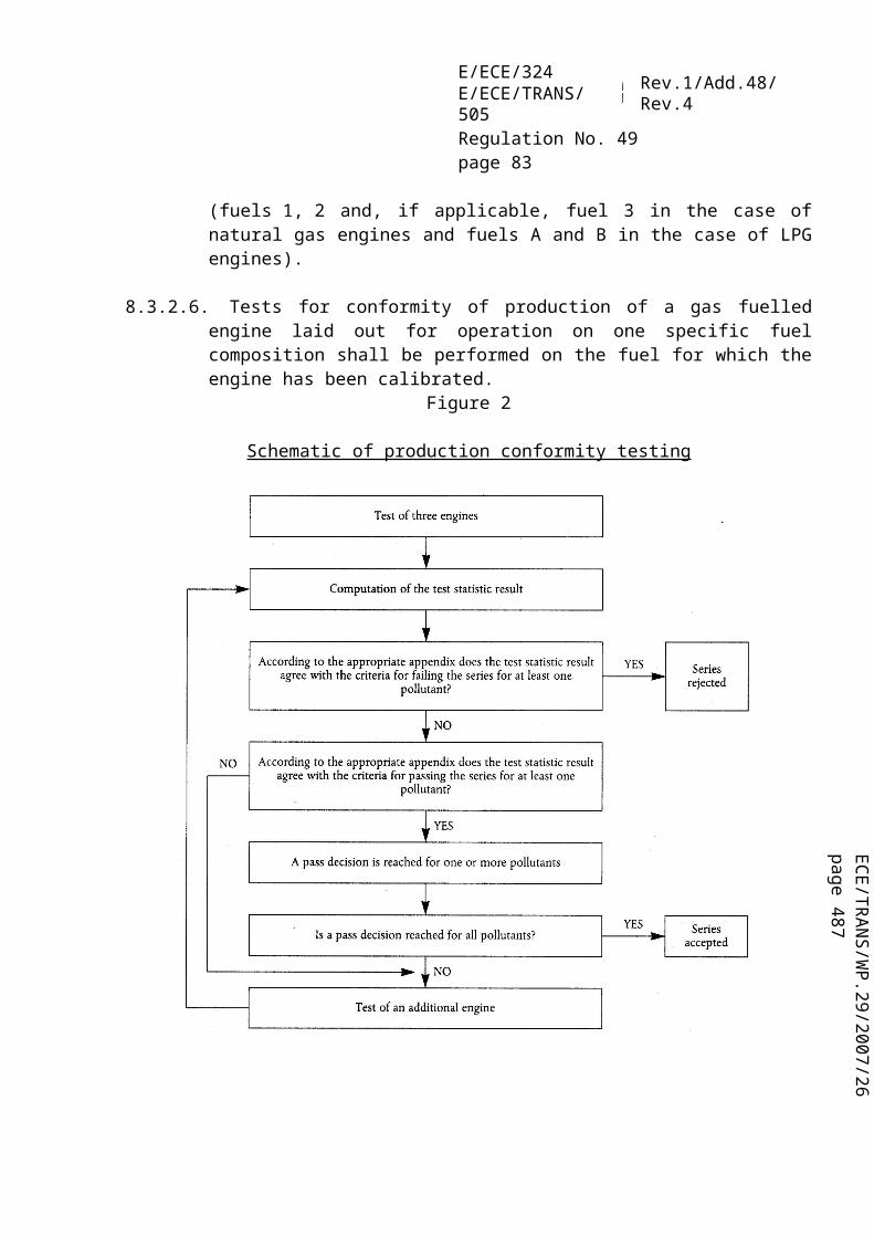
ECE/TR
AN
S/WP.29/2007/26
page 487
E/ECE/324E/ECE/TRANS/505 Rev.1/Add.48/Rev.4
Regulation No. 49page 83Annex 1 – Appendix 3
3.2.8.1.2. Injector(s)3.2.8.1.2.1. Make(s):.................................................................................................................3.2.8.1.2.2. Type(s):..................................................................................................................3.2.8.1.3. Others (if applicable)3.2.8.2. Variant 2
(only in the case of approvals for several specific fuel compositions)
4. Valve timing4.1. Maximum lift of valves and angles of opening and closing in relation to dead centres
of equivalent data:.................................................................................................4.2. Reference and/or setting ranges 2/:.......................................................................
5. Ignition system (spark ignition engines only)5.1. Ignition system type: common coil and plugs/individual coil and plugs/coil on
plug/other (specify) 2/5.2. Ignition control unit5.2.1. Make(s):.................................................................................................................5.2.2. Type(s):..................................................................................................................5.3. Ignition advance curve / advance map 2/ 3/:.........................................................5.4. Ignition timing 3/:......................degrees before TDC at a speed of......................min-1
and a MAP of.........................................................................................................kPa5.5. Spark plugs5.5.1. Make(s):.................................................................................................................5.5.2. Type(s):..................................................................................................................5.5.3. Gap setting:............................................................................................................mm5.6. Ignition coil(s)5.6.1. Make(s):.................................................................................................................5.6.2. Type(s):..................................................................................................................
6. On-board diagnostic (OBD) system6.1. Written description and/or drawing of the MI 4/:6.2. List and purpose of all components monitored by the OBD system:....................6.3. Written description (general OBD working principles) for: 6.3.1. Diesel/gas engines 4/:............................................................................................6.3.1.1. Catalyst monitoring 4/:..........................................................................................6.3.1.2. deNOx system monitoring 4/:...............................................................................6.3.1.3. Diesel particulate filter monitoring 4/:..................................................................6.3.1.4. Electronic fuelling system monitoring 4/:.............................................................6.3.1.5. Other components monitored by the OBD system 4/:...........................................6.4. Criteria for MI activation (fixed number of driving cycles or statistical method):
...............................................................................................................................6.5. List of all OBD output codes and formats used (with explanation of each):........

E/ECE/324E/ECE/TRANS/505 Rev.1/Add.48/Rev.4
Regulation No. 49page 84Annex 1 – Appendix 3
7. Torque limiter7.1. Description of the torque limiter activation7.2. Description of the full load curve limitation

ECE/TR
AN
S/WP.29/2007/26
page 487
E/ECE/324E/ECE/TRANS/505 Rev.1/Add.48/Rev.4
Regulation No. 49page 85Annex 1 – Appendix 4
Annex 1 - Appendix 4
CHARACTERISTICS OF THE ENGINE-RELATED VEHICLE PARTS
1. Intake system depression at rated engine speed and at 100 per cent load:.....................kPa2. Exhaust system back pressure at rated engine speed and at 100 per cent load:..............kPa3. Volume of exhaust system:.............................................................................................cm³4. Power absorbed by the engine-driven auxiliaries as specified in and under the operation
conditions of Regulation No. 24, 03 series of amendments, Annex 10, paragraph 5.1.1. 16/
Equipment Power absorbed (kW) at various engine speedsIdle Low
SpeedHigh Speed
Speed A (a)
Speed B (a)
Speed C (a)
Ref. Speed (b)
Engine-driven auxiliaries
See paragraph 5.1.1. of Regulation No. 24/03, Annex 10.
(a) ESC test.(b) ETC test only.
16/ Data shall be specified for each member of family.

E/ECE/324E/ECE/TRANS/505 Rev.1/Add.48/Rev.4
Regulation No. 49page 86Annex 1 – Appendix 5
Annex 1 - Appendix 5
OBD-RELATED INFORMATION
1. In accordance with the provisions of paragraph 5. of Annex 9A to this Regulation, the following additional information shall be provided by the vehicle manufacturer for the purposes of enabling the manufacture of OBD-compatible replacement or service parts and diagnostic tools and test equipment, unless such information is covered by intellectual property rights or constitutes specific know-how of the manufacturer or the OEM supplier(s). The information given in this paragraph shall be repeated in Annex 2A to this Regulation:
1.1. A description of the type and number of the pre-conditioning cycles used for the original type approval of the vehicle.
1.2. A description of the type of the OBD demonstration cycle used for the original approval of the vehicle for the component monitored by the OBD system.
1.3. A comprehensive document describing all sensed components with the strategy for fault detection and MI activation (fixed number of driving cycles or statistical method), including a list of relevant secondary sensed parameters for each component monitored by the OBD system. A list of all OBD output codes and format used (with an explanation of each) associated with individual emission related powertrain components and individual non-emission related components, where monitoring of the component is used to determine MI activation.
1.3.1.The information required by this paragraph may, for example, be defined by completing a table as follows, which shall be attached to this annex:
Component Fault code
Monitoring strategy
Fault detection criteria
MI activation
criteria
Secondary parameters
Precondi-tioning
Demon-stration test
SCR catalyst PxxxxNOx sensor
1 and 2 signals
Difference between
sensor 1 and sensor 2 signals
3rd cycle
Engine speed, engine load,
catalyst temperature,
reagent activity
Three OBD test cycles (3 short ESC
cycles)
OBD test cycle (short ESC cycle)
1.3.2.The information required by this appendix may be limited to the complete list of the fault codes recorded by the OBD system where paragraph 5.1.2.1. of Annex 9A to this Regulation is not applicable as in the case of replacement or service components. This information may, for example, be defined by completing the two first columns of the table of paragraph 1.3.1. above.

ECE/TR
AN
S/WP.29/2007/26
page 487
E/ECE/324E/ECE/TRANS/505 Rev.1/Add.48/Rev.4
Regulation No. 49page 87Annex 1 – Appendix 5
The complete information package should be made available to the Approval Authority as part of the additional material requested in paragraph 5.1.7.1. "documentation requirements" of this Regulation.
1.3.3.The information required by this paragraph shall be repeated in Annex 2A to this Regulation.
Where paragraph 5.1.2.1. of Annex 9A to this Regulation is not applicable in the case of replacement or service components, the information provided in Annex 2A can be limited to the one mentioned in paragraph 1.3.2.

E/ECE/324E/ECE/TRANS/505 Rev.1/Add.48/Rev.4
Regulation No. 49page 88Annex 2A
Annex 2A
COMMUNICATION
(maximum format: A4 (210 x 297 mm))
issued by: Name of administration:..................................................................................................................
concerning: 2/ APPROVAL GRANTEDAPPROVAL EXTENDEDAPPROVAL REFUSEDAPPROVAL WITHDRAWNPRODUCTION DEFINITELY DISCONTINUED
of a compression-ignition (C.I.) engine type or family (Diesel or Ethanol), or a positive-ignition (P.I.) engine type or family (NG or LPG), 2/ as a separate technical unit with regard to the emission of pollutants pursuant to Regulation No. 49, 05 series of amendments
Approval No. ..... Extension No. .....
1. Trade name or mark of the engine:...................................................................................
2. Engine type / Engine family:............................................................................................
2.1 Manufacturer´s code as marked on the engine 3/: ...........................................................
3. Combustion type: compression-ignition/positive-ignition 2/
3.1. Type of fuel:......................................................................................................................
4. Manufacturer's name and address:....................................................................................
5. If applicable, name and address of manufacturer's representative:
..........................................................................................................................................
6. Maximum allowable intake depression 3/:.................................................................kPa

ECE/TR
AN
S/WP.29/2007/26
page 487
E/ECE/324E/ECE/TRANS/505 Rev.1/Add.48/Rev.4
Regulation No. 49page 89Annex 2A
7. Maximum allowable back-pressure 3/:.......................................................................kPa
8. Maximum permissible power absorbed by the engine-driven equipment 3/:
Idle:.....................kW; Low Speed:........................kW; High Speed:........................kWSpeed A:..................kW; Speed B:........................kW; Speed C:.................................kW;Reference Speed:........................................................................................................kW
9. Volume of exhaust system:.........................................................................................cm3
10. Restrictions of use (if any):...............................................................................................
11. Emission levels of the engine/parent engine 2/
11.1. Emission stage (according to table in paragraph 4.6.3.) .................................................
11.2. ESC test (if applicable):
Deterioration factor (DF): calculated/fixed 2/
Specify the DF values and the emissions on the ESC test in the table below:
ESC test
DF: CO THC NOx PT
Emissions CO(g/kWh)
THC(g/kWh)
NOx
(g/kWh)PT
(g/kWh)Measured:
Calculated with DF:
11.3. ELR test (if applicable):smoke value:............................................................................................m-1
11.4. ETC test:Deterioration factor (DF): calculated/fixed 2/

E/ECE/324E/ECE/TRANS/505 Rev.1/Add.48/Rev.4
Regulation No. 49page 90Annex 2A
ETC test
DF: CO NMHC CH4 NOx PT
Emissions CO(g/kWh)
NMHC(g/kWh) 2/
CH4
(g/kWh) 2/NOx
(g/kWh)PT
(g/kWh) 2/Measured with regeneration:Measured without regeneration:Measured/weighted:Calculated with DF:
12. Engine submitted for tests on:..........................................................................................
13. Technical service responsible for conducting the approval tests:
14. Date of test report issued by that service:.........................................................................
15. Number of the test report issued by that service:..............................................................
16 Site of approval mark on the engine:................................................................................
17. Reasons for extension:......................................................................................................
18 Place:.................................................................................................................................
19 Date: .................................................................................................................................
20. Signature: .........................................................................................................................
21. The following documents, bearing the approval number shown above, are annexed to this communication:
One copy of Annex 1 to this Regulation completed and with the drawings and diagrams referred to attached.
____________________1/ Distinguishing number of the country which has granted/extended/refused/withdrawn approval (see approval provisions in the Regulation).2/ Strike out what does not apply.3/ For each member of the family.

ECE/TR
AN
S/WP.29/2007/26
page 487
E/ECE/324E/ECE/TRANS/505 Rev.1/Add.48/Rev.4
Regulation No. 49page 91Annex 2A - Appendix
Annex 2A - Appendix
OBD-RELATED INFORMATION
As noted in Appendix 4 of Annex 1 to this Regulation, the information in this appendix is provided by the engine/vehicle manufacturer for the purposes of enabling the manufacture of OBD-compatible replacement or service parts and diagnostic tools and test equipment. Such information need not be supplied by the engine/vehicle manufacturer if it is covered by intellectual property rights or constitutes specific know-how of the manufacturer or the OEM supplier(s).
Upon request, this appendix will be made available to any interested component, diagnostic tools or test equipment manufacturer, on a non-discriminatory basis.
In compliance with the provisions of paragraph 1.3.3. of Appendix 4 to Annex 1, the information required by this paragraph shall be identical to that provided in that Appendix.
1. A description of the type and number of the pre-conditioning cycles used for the original type approval of the vehicle.
2. A description of the type of the OBD demonstration cycle used for the original type approval of the vehicle for the component monitored by the OBD system.
3. A comprehensive document describing all sensed components with the strategy for fault detection and MI activation (fixed number of driving cycles or statistical method), including a list of relevant secondary sensed parameters for each component monitored by the OBD system. A list of all OBD output codes and format used (with an explanation of each) associated with individual emission related powertrain components and individual non-emission related components, where monitoring of the component is used to determine MI activation.

E/ECE/324E/ECE/TRANS/505 Rev.1/Add.48/Rev.4
Regulation No. 49page 92Annex 2B
Annex 2B
COMMUNICATION
(maximum format: A4 (210 x 297 mm))
issued by: Name of administration:...............................................................................................................
concerning: 2/ APPROVAL GRANTEDAPPROVAL EXTENDEDAPPROVAL REFUSEDAPPROVAL WITHDRAWNPRODUCTION DEFINITELY DISCONTINUED
of a vehicle type with regard to the emission of pollutants by the engine pursuant to Regulation No. 49
Approval No. ... Extension No. ...
1. Trade name or mark of the engine:.......................................................................................
1.1. Make and type of the engine:...............................................................................................
1.2. Manufacturer's code as marked on the engine: ....................................................................
2. Vehicle make and type:........................................................................................................
3. Manufacturer's name and address:........................................................................................
4. If applicable, name and address of manufacturer's representative:....................................................................................................................................................................................
5. Maximum allowable intake depression:.........................................................................kPa
6. Maximum allowable back-pressure: ..............................................................................kPa
7. Maximum permissible power absorbed by the engine-driven equipment:Idle:.....................kW; Low Speed:........................kW; High Speed:.............................kWSpeed A:..................kW; Speed B:........................kW; Speed C:..................................kW;Reference Speed:......................................................................................................................................................................................................................................................kW

ECE/TR
AN
S/WP.29/2007/26
page 487
E/ECE/324E/ECE/TRANS/505 Rev.1/Add.48/Rev.4
Regulation No. 49page 93Annex 2B
8. Volume of the exhaust system:.......................................................................................cm3
9. Emission levels of the engine/parent engine
9.1. Emission stage (according to table in paragraph 4.6.3.) ...................
9.2. ESC test (if applicable):
Deterioration factor (DF): calculated/fixed 2/
Specify the DF values and the emissions on the ESC test in the table below:
ESC test
DF: CO THC NOx PT
Emissions CO(g/kWh)
THC(g/kWh)
NOx
(g/kWh)PT
(g/kWh)Measured:
Calculated with DF:
9.3. ELR test (if applicable):smoke value:............................................................................................m-1
9.4. ETC test:Deterioration factor (DF): calculated/fixed 2/
ETC test
DF: CO NMHC CH4 NOx PT
Emissions CO(g/kWh)
NMHC(g/kWh) 2/
CH4
(g/kWh) 2/NOx
(g/kWh)PT
(g/kWh) 2/Measured with regeneration:Measured without regeneration:Measured/weighted:Calculated with DF:
10. Engine submitted for tests on:..............................................................................................
11. Technical Service responsible for conducting the approval tests:......................................................................................................................................................................................
12. Date of test report issued by that service:.............................................................................

E/ECE/324E/ECE/TRANS/505 Rev.1/Add.48/Rev.4
Regulation No. 49page 94Annex 2B
13. Number of test report issued by that service:.......................................................................
14. Approval number of the engine/engine family, if approved as a separate technical unit:..............................................................................................................................................
15. Site of approval mark on the vehicle/engine 2/:...................................................................
16. Reasons for extension:..........................................................................................................
17. Place:....................................................................................................................................
18. Date:......................................................................................................................................
19. Signature:..............................................................................................................................
___________________1/ Distinguishing number of the country which has granted/extended/refused/withdrawn approval (see approval provisions in the Regulation).2/ Strike out what does not apply.

ECE/TR
AN
S/WP.29/2007/26
page 487
E/ECE/324E/ECE/TRANS/505 Rev.1/Add.48/Rev.4
Regulation No. 49page 95Annex 3
Annex 3
ARRANGEMENTS OF APPROVAL MARKS(See table in paragraph 4.6.3. of this Regulation)
I. APPROVAL "B" (Row B1, OBD stage 1, without NOx control).
Example 1Diesel engines:
Example 2
Natural gas (NG) engines:The suffix after the national symbol indicates the fuel qualification determined in accordance with paragraph 4.6.3.1. of this Regulation.
The above approval marks affixed to an engine/vehicle show that the engine/vehicle type concerned has been approved in the United Kingdom (E11) pursuant to Regulation No 49 and under approval number 052439. This approval indicates that the approval was given in accordance with the requirements of Regulation No. 49 with the 05 series of amendments incorporated and satisfying the relevant emission stages detailed in paragraph 4.6.3. of this Regulation.
II. APPROVAL "C" (Row B1, OBD stage 1, with NOx control).
Example 3
Diesel engines:
HLta3
aa2 E 11 49 RB - 052439a
3
a = 8 mm min.
aa2 E 11 49 RB - 052439a
3
a = 8 mm min.
aa2 E 11 49 RC - 052439a
3
a = 8 mm min .

E/ECE/324E/ECE/TRANS/505 Rev.1/Add.48/Rev.4
Regulation No. 49page 96Annex 3
The above approval mark affixed to an engine/vehicle shows that the engine/vehicle type concerned has been approved in the United Kingdom (E11) pursuant to Regulation No. 49 and under approval number 052439. This approval indicates that the approval was given in accordance with the requirements of Regulation No. 49 with the 05 series of amendments incorporated and satisfying the relevant emission stages detailed in paragraph 4.6.3. of this Regulation.
III. APPROVAL "F" (Row B2, OBD stage 2, without NOx control).
Example 4
LPG engines:
The above approval mark affixed to an engine/vehicle shows that the engine/vehicle type concerned has been approved in the United Kingdom (E11) pursuant to Regulation No. 49 and under approval number 052439. This approval indicates that the approval was given in accordance with the requirements of Regulation No. 49 with the 05 series of amendments incorporated and satisfying the relevant emission stages detailed in paragraph 4.6.3. of this Regulation.
IV. APPROVAL "G" (Row B2, OBD stage 2, with NOx control).
Example 5
Diesel engine:
The above approval mark affixed to an engine/vehicle shows that the engine/vehicle type concerned has been approved in the United Kingdom (E11) pursuant to Regulation No. 49 and under approval number 052439. This approval indicates that the approval was given in accordance with the requirements of Regulation No. 49 with the 05 series of amendments incorporated and satisfying the relevant emission stages detailed in paragraph 4.6.3. of this Regulation.
aa2 E 11 49 RF - 052439a
3
a = 8 mm min.
aa2 E 11 49 RG - 052439a
3
a = 8 mm min.

ECE/TR
AN
S/WP.29/2007/26
page 487
E/ECE/324E/ECE/TRANS/505 Rev.1/Add.48/Rev.4
Regulation No. 49page 97Annex 3
V. APPROVAL "J" (Row C, OBD stage 2, without NOx control).
Example 6
LPG engine:
The above approval mark affixed to an engine/vehicle shows that the engine/vehicle type concerned has been approved in the United Kingdom (E11) pursuant to Regulation No. 49 and under approval number 052439. This approval indicates that the approval was given in accordance with the requirements of Regulation No. 49 with the 05 series of amendments incorporated and satisfying the relevant emission stages detailed in paragraph 4.6.3. of this Regulation.
VI. ENGINE/VEHICLE APPROVED TO ONE OR MORE REGULATIONS(See paragraph 4.7. of this Regulation)
Example 7
The above approval mark affixed to a HL natural gas engine/vehicle shows that the engine/vehicle type concerned has been approved in the United Kingdom (E11) pursuant to Regulation No. 49 (emission stage G) and Regulation No. 24 1/. The first two digits of the approval numbers indicate that, at the dates when the respective approvals were given, Regulation No. 49 included the 05 series of amendments, and Regulation No. 24 the 03 series of amendments.
__________1/ The second Regulation number is given merely as an example.
49 G HL24 03 1628
05 2439a2a E 11 a
3
a2
a2
a3
a3
aa2 E 11 49 RJ - 052439a
3
a = 8 mm min.

E/ECE/324E/ECE/TRANS/505 Rev.1/Add.48/Rev.4
Regulation No. 49page 98Annex 4A
Annex 4A
TEST PROCEDURE
1. INTRODUCTION
1.1. This annex describes the methods of determining emissions of gaseous components, particulates and smoke from the engines to be tested. Three test cycles are described that shall be applied according to the provisions of paragraph 5.2.:(a) the ESC which consists of a steady state 13-mode cycle,(b) the ELR which consists of transient load steps at different speeds, which are integral
parts of one test procedure, and are run concurrently,(c) the ETC which consists of a second-by-second sequence of transient modes.
1.2. The test shall be carried out with the engine mounted on a test bench and connected to a dynamometer.
1.3. Measurement principle
The emissions to be measured from the exhaust of the engine include the gaseous components (carbon monoxide, total hydrocarbons for diesel engines on the ESC test only; non-methane hydrocarbons for diesel and gas engines on the ETC test only; methane for gas engines on the ETC test only and oxides of nitrogen), the particulates (diesel engines only) and smoke (diesel engines on the ELR test only). Additionally, carbon dioxide is often used as a tracer gas for determining the dilution ratio of partial and full flow dilution systems. Good engineering practice recommends the general measurement of carbon dioxide as an excellent tool for the detection of measurement problems during the test run.
1.3.1.ESC Test
During a prescribed sequence of warmed-up engine operating conditions the amounts of the above exhaust emissions shall be examined continuously by taking a sample from the raw or diluted exhaust gas. The test cycle consists of a number of speed and power modes which cover the typical operating range of diesel engines. During each mode the concentration of each gaseous pollutant, exhaust flow and power output shall be determined, and the measured values weighted. For particulate measurement, the exhaust gas shall be diluted with conditioned ambient air using either a partial flow or full flow dilution system. The particulates shall be collected on a single suitable filter in proportion to the weighting factors of each mode. The grams of each pollutant emitted per kilowatt hour shall be calculated as described in Appendix 1 to this annex. Additionally, NOx shall be measured at three test points within the control area selected by the Technical Service and the measured values compared to the values calculated from those modes of the test cycle enveloping the selected test points. The NOx control check ensures the

ECE/TR
AN
S/WP.29/2007/26
page 487
E/ECE/324E/ECE/TRANS/505 Rev.1/Add.48/Rev.4
Regulation No. 49page 99Annex 4A
effectiveness of the emission control of the engine within the typical engine operating range.
1.3.2.ELR Test
During a prescribed load response test, the smoke of a warmed-up engine shall be determined by means of an opacimeter. The test consists of loading the engine at constant speed from 10 per cent to 100 per cent load at three different engine speeds. Additionally, a fourth load step selected by the Technical Service 17/ shall be run, and the value compared to the values of the previous load steps. The smoke peak shall be determined using an averaging algorithm, as described in Appendix 1 to this annex.
1.3.3.ETC Test
During a prescribed transient cycle of warmed-up engine operating conditions, which is based closely on road-type-specific driving patterns of heavy-duty engines installed in trucks and buses, the above pollutants shall be examined either after diluting the total exhaust gas with conditioned ambient air (CVS system with double dilution for particulates) or by determining the gaseous components in the raw exhaust gas and the particulates with a partial flow dilution system. Using the engine torque and speed feedback signals of the engine dynamometer, the power shall be integrated with respect to time of the cycle resulting in the work produced by the engine over the cycle. For a CVS system, the concentration of NOx and HC shall be determined over the cycle by integration of the analyzer signal, whereas the concentration of CO, CO2, and NMHC may be determined by integration of the analyzer signal or by bag sampling. If measured in the raw exhaust gas, all gaseous components shall be determined over the cycle by integration of the analyzer signal. For particulates, a proportional sample shall be collected on a suitable filter. The raw or diluted exhaust gas flow rate shall be determined over the cycle to calculate the mass emission values of the pollutants. The mass emission values shall be related to the engine work to get the grams of each pollutant emitted per kilowatt hour, as described in Appendix 2 to this annex.
2. TEST CONDITIONS
2.1. Engine test conditions
2.1.1.The absolute temperature (Ta) of the engine air at the inlet to the engine expressed in Kelvin, and the dry atmospheric pressure (ps), expressed in kPa shall be measured and the parameter fa shall be determined according to the following provisions. In multi-cylinder engines having distinct groups of intake manifolds, for example, in a "V" engine configuration, the average temperature of the distinct groups shall be taken.
(a) for compression-ignition engines:
17/ The test points shall be selected using approved statistical methods of randomisation.

E/ECE/324E/ECE/TRANS/505 Rev.1/Add.48/Rev.4
Regulation No. 49page 100Annex 4A
Naturally aspirated and mechanically supercharged engines:
Turbocharged engines with or without cooling of the intake air:
(b) for spark-ignition engines:
2.1.2.Test validity
For a test to be recognized as valid, the parameter fa shall be such that:0.96 fa 1.06
2.2. Engines with charge air cooling
The charge air temperature shall be recorded and shall be, at the speed of the declared maximum power and full load, within ± 5 K of the maximum charge air temperature specified in Annex 1, Appendix 1, paragraph 1.16.3. The temperature of the cooling medium shall be at least 293 K (20 °C).
If a test shop system or external blower is used, the charge air temperature shall be within ± 5 K of the maximum charge air temperature specified in Annex 1, Appendix 1, paragraph 1.16.3. at the speed of the declared maximum power and full load. The setting of the charge air cooler for meeting the above conditions shall be used for the whole test cycle.
2.3. Engine air intake system
An engine air intake system shall be used presenting an air intake restriction within ± 100 Pa of the upper limit of the engine operating at the speed at the declared maximum power and full load.
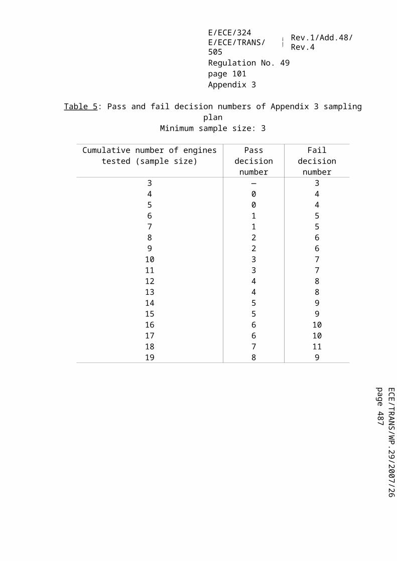
ECE/TR
AN
S/WP.29/2007/26
page 487
E/ECE/324E/ECE/TRANS/505 Rev.1/Add.48/Rev.4
Regulation No. 49page 101Annex 4A
2.4. Engine exhaust system
An exhaust system shall be used presenting an exhaust back pressure within ± 1,000 Pa of the upper limit of the engine operating at the speed of declared maximum power and full load and a volume within ± 40 per cent of that specified by the manufacturer. A test shop system may be used, provided it represents actual engine operating conditions. The exhaust system shall conform to the requirements for exhaust gas sampling, as set out in paragraph 3.4. of Appendix 4 to this annex, and in Appendix 7, paragraph 2.2.1., EP and paragraph 2.3.1., EP.
If the engine is equipped with an exhaust aftertreatment device, the exhaust pipe shall have the same diameter as found in-use for at least 4 pipe diameters upstream to the inlet of the beginning of the expansion section containing the aftertreatment device. The distance from the exhaust manifold flange or turbocharger outlet to the exhaust aftertreatment device shall be the same as in the vehicle configuration or within the distance specifications of the manufacturer. The exhaust backpressure or restriction shall follow the same criteria as above, and may be set with a valve. The aftertreatment container may be removed during dummy tests and during engine mapping, and replaced with an equivalent container having an inactive catalyst support.
2.5. Cooling system
An engine cooling system with sufficient capacity to maintain the engine at normal operating temperatures prescribed by the manufacturer shall be used.
2.6. Lubricating oil
Specifications of the lubricating oil used for the test shall be recorded and presented with the results of the test, as specified in Annex 1, Appendix 1, paragraph 7.1.
2.7. Fuel
The fuel shall be the reference fuel specified in Annex 5.
The fuel temperature and measuring point shall be specified by the manufacturer within the limits given in Annex 1, paragraph 1.16.5. The fuel temperature shall not be lower than 306 K (33 °C). If not specified, it shall be 311 K ± 5 K (38 °C ± 5 °C) at the inlet to the fuel supply.
For NG and LPG fuelled engines, the fuel temperature and measuring point shall be within the limits given in Annex 1, paragraph 1.16.5. or in Annex 1, Appendix 3, paragraph 1.16.5. in cases where the engine is not a parent engine.

E/ECE/324E/ECE/TRANS/505 Rev.1/Add.48/Rev.4
Regulation No. 49page 102Annex 4A
2.8. Testing of exhaust aftertreatment systems
If the engine is equipped with an exhaust aftertreatment system, the emissions measured on the test cycle shall be representative of the emissions in the field. In the case of an engine equipped with a exhaust aftertreatment system that requires the consumption of a reagent, the reagent used for all tests shall comply with Annex 1, paragraph 2.2.1.13.
2.8.1. For an exhaust aftertreatment system based on a continuous regeneration process the emissions shall be measured on a stabilised aftertreatment system.
The regeneration process shall occur at least once during the ETC test and the manufacturer shall declare the normal conditions under which regeneration occurs (soot load, temperature, exhaust back-pressure, etc).
In order to verify the regeneration process at least 5 ETC tests shall be conducted. During the tests the exhaust temperature and pressure shall be recorded (temperature before and after the aftertreatment system, exhaust back pressure, etc).
The aftertreatment system is considered to be satisfactory if the conditions declared by the manufacturer occur during the test during a sufficient time.
The final test result shall be the arithmetic mean of the different ETC test results.
If the exhaust aftertreatment has a security mode that shifts to a periodic regeneration mode it should be checked following paragraph 2.8.2. of this annex. For that specific case the emission limits in table 2 of paragraph 5.2. could be exceeded and would not be weighted.
2.8.2. For an exhaust aftertreatment based on a periodic regeneration process, the emissions shall be measured on at least two ETC tests, one during and one outside a regeneration event on a stabilised aftertreatment system, and the results be weighted.
The regeneration process shall occur at least once during the ETC test. The engine may be equipped with a switch capable of preventing or permitting the regeneration process provided this operation has no effect on the original engine calibration.
The manufacturer shall declare the normal parameter conditions under which the regeneration process occurs (soot load, temperature, exhaust back-pressure etc) and its duration time (n2). The manufacturer shall also provide all the data to determine the time between two regenerations (n1). The exact procedure to determine this time shall be agreed by the Technical Service based upon good engineering judgement.

ECE/TR
AN
S/WP.29/2007/26
page 487
E/ECE/324E/ECE/TRANS/505 Rev.1/Add.48/Rev.4
Regulation No. 49page 103Annex 4A
The manufacturer shall provide an aftertreatment system that has been loaded in order to achieve regeneration during an ETC test. Regeneration shall not occur during this engine conditioning phase.
Average emissions between regeneration phases shall be determined from the arithmetic mean of several approximately equidistant ETC tests. It is recommended to run at least one ETC as close as possible prior to a regeneration test and one ETC immediately after a regeneration test. As an alternative, the manufacturer may provide data to show that the emissions remain constant (15 per cent) between regeneration phases. In this case, the emissions of only one ETC test may be used.
During the regeneration test, all the data needed to detect regeneration shall be recorded (CO or NOx emissions, temperature before and after the aftertreatment system, exhaust back pressure etc).
During the regeneration process, the emission limits in table 2 of paragraph 5.2. can be exceeded.
The measured emissions shall be weighted according to paragraphs 5.5. and 6.3. of Appendix 2 to this annex and the final result shall not exceed the limits in table 2 of paragraph 5.2.

E/ECE/324E/ECE/TRANS/505 Rev.1/Add.48/Rev.4
Regulation No. 49page 104Annex 4A – Appendix 1
Annex 4A - Appendix 1
ESC AND ELR TEST CYCLES
1. ENGINE AND DYNAMOMETER SETTINGS
1.1 Determination of engine speeds A, B and C
The engine speeds A, B and C shall be declared by the manufacturer in accordance with the following provisions:
The high speed nhi shall be determined by calculating 70 per cent of the declared maximum net power P(n), as determined in Annex 1, paragraph 8.2. The highest engine speed where this power value occurs on the power curve is defined as nhi.
The low speed nlo shall be determined by calculating 50 per cent of the declared maximum net power P(n), as determined in Annex 1, paragraph 8.2. The lowest engine speed where this power value occurs on the power curve is defined as nlo.
The engine speeds A, B and C shall be calculated as follows:Speed A = nlo + 25 per cent (nhi − nlo)Speed B = nlo + 50 per cent (nhi − nlo)Speed C = nlo + 75 per cent (nhi − nlo)
The engine speeds A, B and C may be verified by either of the following methods:(a) Additional test points shall be measured during engine power approval according to
Regulation 85 for an accurate determination of nhi and nlo. The maximum power, nhi
and nlo shall be determined from the power curve, and engine speeds A, B and C shall be calculated according to the above provisions.
(b) The engine shall be mapped along the full load curve, from maximum no load speed to idle speed, using at least 5 measurement points per 1,000 min-1 intervals and measurement points within ± 50 min-1 of the speed at declared maximum power. The maximum power, nhi and nlo shall be determined from this mapping curve, and engine speeds A, B and C shall be calculated according to the above provisions.
If the measured engine speeds A, B and C are within ± 3 per cent of the engine speeds as declared by the manufacturer, the declared engine speeds shall be used for the emissions test. If the tolerance is exceeded for any of the engine speeds, the measured engine speeds shall be used for the emissions test.
1.2. Determination of dynamometer settings
The torque curve at full load shall be determined by experimentation to calculate the torque values for the specified test modes under net conditions, as specified in Annex 1,

ECE/TR
AN
S/WP.29/2007/26
page 487
E/ECE/324E/ECE/TRANS/505 Rev.1/Add.48/Rev.4
Regulation No. 49page 105Annex 4A – Appendix 1
paragraph 8.2. The power absorbed by engine-driven equipment, if applicable, shall be taken into account. The dynamometer setting for each test mode shall be calculated using the formula:
s = P(n) x (L/100) if tested under net conditionss = P(n) x (L/100) + (P(a) − P(b)) if not tested under net conditions
where:
s = dynamometer setting, kWP(n) = net engine power as indicated in Annex 1, paragraph 8.2., kWL = per cent load as indicated in paragraph 2.7.1., per centP(a) = power absorbed by auxiliaries to be fitted as indicated in Annex 1,
paragraph 6.1.P(b) = power absorbed by auxiliaries to be removed as indicated in Annex 1,
paragraph 6.2.
2. ESC TEST RUN
At the manufacturers request, a dummy test may be run for conditioning of the engine and exhaust system before the measurement cycle.
2.1. Preparation of the sampling filter
At least one hour before the test, each filter shall be placed in a partially covered petri dish which is protected against dust contamination, and placed in a weighing chamber for stabilisation. At the end of the stabilisation period each filter shall be weighed and the tare weight shall be recorded. The filter shall then be stored in a closed petri dish or sealed filter holder until needed for testing. The filter shall be used within eight hours of its removal from the weighing chamber. The tare weight shall be recorded.
2.2. Installation of the measuring equipment
The instrumentation and sample probes shall be installed as required. When using a full flow dilution system for exhaust gas dilution, the tailpipe shall be connected to the system.
2.3. Starting the dilution system and the engine
The dilution system and the engine shall be started and warmed up until all temperatures and pressures have stabilised at maximum power according to the recommendation of the manufacturer and good engineering practice.

E/ECE/324E/ECE/TRANS/505 Rev.1/Add.48/Rev.4
Regulation No. 49page 106Annex 4A – Appendix 1
2.4. Starting the particulate sampling system
The particulate sampling system shall be started and running on by-pass. The particulate background level of the dilution air may be determined by passing dilution air through the particulate filters. If filtered dilution air is used, one measurement may be done prior to or after the test. If the dilution air is not filtered, measurements at the beginning and at the end of the cycle, may be done, and the values averaged.
2.5. Adjustment of the dilution ratio
The dilution air shall be set such that the temperature of the diluted exhaust gas measured immediately prior to the filter shall not exceed 325 K (52 °C) at any mode. The dilution ratio (q) shall not be less than 4.
For systems that use CO2 or NOx concentration measurement for dilution ratio control, the CO2 or NOx content of the dilution air shall be measured at the beginning and at the end of each test. The pre- and post test background CO2 or NOx concentration measurements of the dilution air shall be within 100 ppm or 5 ppm of each other, respectively.
2.6. Checking the analyzers
The emission analyzers shall be set at zero and spanned. The sample bags, if used, shall be evacuated.
2.7. Test cycle
2.7.1.The following 13-mode cycle shall be followed in dynamometer operation on the test engine
Mode Number Engine Speed Per cent Load Weighting Factor Mode Length1 idle — 0.15 4 minutes2 A 100 0.08 2 minutes3 B 50 0.10 2 minutes4 B 75 0.10 2 minutes5 A 50 0.05 2 minutes6 A 75 0.05 2 minutes7 A 25 0.05 2 minutes8 B 100 0.09 2 minutes9 B 25 0.10 2 minutes10 C 100 0.08 2 minutes11 C 25 0.05 2 minutes12 C 75 0.05 2 minutes13 C 50 0.05 2 minutes

ECE/TR
AN
S/WP.29/2007/26
page 487
E/ECE/324E/ECE/TRANS/505 Rev.1/Add.48/Rev.4
Regulation No. 49page 107Annex 4A – Appendix 1
2.7.2.Test sequence
The test sequence shall be started. The test shall be performed in the order of the mode numbers as set out in paragraph 2.7.1.
The engine shall be operated for the prescribed time in each mode, completing engine speed and load changes in the first 20 seconds. The specified speed shall be held to within ± 50 min-1 and the specified torque shall be held to within ± 2 per cent of the maximum torque at the test speed.
At the manufacturer's request, the test sequence may be repeated a sufficient number of times for sampling more particulate mass on the filter. The manufacturer shall supply a detailed description of the data evaluation and calculation procedures. The gaseous emissions shall only be determined on the first cycle.
2.7.3.Analyzer response
The output of the analyzers shall be recorded on a strip chart recorder or measured with an equivalent data acquisition system with the exhaust gas flowing through the analyzers throughout the test cycle.
2.7.4.Particulate sampling
A single filter shall be used for the complete test procedure. The modal weighting factors specified in the test cycle procedure shall be taken into account by taking a sample proportional to the exhaust mass flow during each individual mode of the cycle. This can be achieved by adjusting sample flow rate, sampling time, and/or dilution ratio, accordingly, so that the criterion for the effective weighting factors in paragraph 6.6. is met.
The sampling time per mode shall be at least 4 seconds per 0.01 weighting factor. Sampling shall be conducted as late as possible within each mode. Particulate sampling shall be completed no earlier than 5 seconds before the end of each mode.
2.7.5.Engine conditions
The engine speed and load, intake air temperature and depression, exhaust temperature and backpressure, fuel flow and air or exhaust flow, charge air temperature, fuel temperature and humidity shall be recorded during each mode, with the speed and load requirements (see paragraph 2.7.2.) being met during the time of particulate sampling, but in any case during the last minute of each mode.
Any additional data required for calculation shall be recorded (see paragraphs 4. and 5.).

E/ECE/324E/ECE/TRANS/505 Rev.1/Add.48/Rev.4
Regulation No. 49page 108Annex 4A – Appendix 1
2.7.6.NOx check within the control area
The NOx check within the control area shall be performed immediately upon completion of mode 13.
The engine shall be conditioned at mode 13 for a period of three minutes before the start of the measurements. Three measurements shall be made at different locations within the control area, selected by the Technical Service 18/. The time for each measurement shall be 2 minutes.
The measurement procedure is identical to the NOx measurement on the 13-mode cycle, and shall be carried out in accordance with paragraphs 2.7.3., 2.7.5., and 4.1. of this appendix, and Appendix 4, paragraph 3.
The calculation shall be carried out in accordance with paragraph 4.
2.7.7.Rechecking the analyzers
After the emission test a zero gas and the same span gas shall be used for rechecking. The test will be considered acceptable if the difference between the pre-test and post-test results is less than 2 per cent of the span gas value.
3. ELR TEST RUN
3.1. Installation of the measuring equipment
The opacimeter and sample probes, if applicable, shall be installed after the exhaust silencer or any aftertreatment device, if fitted, according to the general installation procedures specified by the instrument manufacturer. Additionally, the requirements of paragraph 10. of ISO 11614 shall be observed.
Prior to any zero and full-scale checks, the opacimeter shall be warmed up and stabilised according to the instrument manufacturer's recommendations. If the opacimeter is equipped with a purge air system to prevent sooting of the meter optics, this system shall also be activated and adjusted according to the manufacturer's recommendations.
3.2. Checking of the opacimeter
The zero and full scale checks shall be made in the opacity readout mode, since the opacity scale offers two truly definable calibration points, namely 0 per cent opacity and 100 per cent opacity. The light absorption coefficient is then correctly calculated based upon the
18/ The test points shall be selected using approved statistical methods of randomisation.

ECE/TR
AN
S/WP.29/2007/26
page 487
E/ECE/324E/ECE/TRANS/505 Rev.1/Add.48/Rev.4
Regulation No. 49page 109Annex 4A – Appendix 1
measured opacity and the LA, as submitted by the opacimeter manufacturer, when the instrument is returned to the k readout mode for testing.
With no blockage of the opacimeter light beam, the readout shall be adjusted to 0.0 per cent ± 1.0 per cent opacity. With the light being prevented from reaching the receiver, the readout shall be adjusted to 100.0 per cent ± 1.0 per cent opacity.
3.3. Test cycle
3.3.1.Conditioning of the engine
Warming up of the engine and the system shall be at maximum power in order to stabilise the engine parameters according to the recommendation of the manufacturer. The preconditioning phase should also protect the actual measurement against the influence of deposits in the exhaust system from a former test.
When the engine is stabilised, the cycle shall be started within 20 ± 2 s after the preconditioning phase. At the manufacturer's request, a dummy test may be run for additional conditioning before the measurement cycle.
3.3.2.Test sequence
The test consists of a sequence of three load steps at each of the three engine speeds A (cycle 1), B (cycle 2) and C (cycle 3) determined in accordance with Annex 4A, paragraph 1.1., followed by cycle 4 at a speed within the control area and a load between 10 per cent and 100 per cent, selected by the Technical Service 19/. The following sequence shall be followed in dynamometer operation on the test engine, as shown in figure 3.
19/ The test points shall be selected using approved statistical methods of randomisation.

E/ECE/324E/ECE/TRANS/505 Rev.1/Add.48/Rev.4
Regulation No. 49page 110Annex 4A – Appendix 1
Figure 3Sequence of ELR Test
(a) The engine shall be operated at engine speed A and 10 per cent load for 20 ± 2 s. The specified speed shall be held to within ± 20 min-1 and the specified torque shall be held to within ± 2 per cent of the maximum torque at the test speed.
(b) At the end of the previous segment, the speed control lever shall be moved rapidly to, and held in, the wide open position for 10 ± 1 s. The necessary dynamometer load shall be applied to keep the engine speed within ± 150 min-1 during the first 3 s, and within ± 20 min-1 during the rest of the segment.
(c) The sequence described in (a) and (b) shall be repeated two times.(d) Upon completion of the third load step, the engine shall be adjusted to engine speed
B and 10 per cent load within 20 ± 2 s.(e) The sequence (a) to (c) shall be run with the engine operating at engine speed B.(f) Upon completion of the third load step, the engine shall be adjusted to engine
speed C and 10 per cent load within 20 ± 2 s.(g) The sequence (a) to (c) shall be run with the engine operating at engine speed C.(h) Upon completion of the third load step, the engine shall be adjusted to the selected
engine speed and any load above 10 per cent within 20 ± 2 s.(i) The sequence (a) to (c) shall be run with the engine operating at the selected engine
speed.
3.4. Cycle validation
The relative standard deviations of the mean smoke values at each test speed (SVA, SVB, SVC, as calculated in accordance with paragraph 7.3.3. of this appendix from the three successive load steps at each test speed) shall be lower than 15 per cent of the mean value,
ECE/TR
AN
S/WP.29/2007/26
page 487
E/ECE/324E/ECE/TRANS/505 Rev.1/Add.48/Rev.4
Regulation No. 49page 111Annex 4A – Appendix 1
or 10 per cent of the limit value shown in table 1 of paragraph 5.2., whichever is greater. If the difference is greater, the sequence shall be repeated until 3 successive load steps meet the validation criteria.
3.5. Rechecking of the opacimeter
The post-test opacimeter zero drift value shall not exceed ± 5.0 per cent of the limit value shown in table 1 of paragraph 5.2.
4. CALCULATION OF THE EXHAUST GAS FLOW
4.1. Determination of raw exhaust gas mass flow
For calculation of the emissions in the raw exhaust, it is necessary to know the exhaust gas flow. The exhaust gas mass flow rate shall be determined in accordance with paragraph 4.1.1. or 4.1.2. The accuracy of exhaust flow determination shall be ± 2.5 per cent of reading or 1.5 per cent of the engine's maximum value whichever is the greater. Equivalent methods (e.g. those described in paragraph 4.2. of Appendix 2 to this annex) may be used.
4.1.1.Direct measurement method
Direct measurement of the exhaust flow may be done by systems such as:(a) pressure differential devices, like flow nozzle;(b) ultrasonic flowmeter;(c) vortex flowmeter.
Precautions shall be taken to avoid measurement errors which will impact emission value errors. Such precautions include the careful installation of the device in the engine exhaust system according to the instrument manufacturers" recommendations and to good engineering practice. Especially, engine performance and emissions shall not be affected by the installation of the device.
4.1.2.Air and fuel measurement method
This involves measurement of the air flow and the fuel flow. Air flowmeters and fuel flowmeters shall be used that meet the total accuracy requirement of paragraph 4.1. The calculation of the exhaust gas flow is as follows:
mfmawmew qqq
4.2. Determination of diluted exhaust gas mass flow
For calculation of the emissions in the diluted exhaust using a full flow dilution system it is necessary to know the diluted exhaust gas flow. The flow rate of the diluted exhaust

E/ECE/324E/ECE/TRANS/505 Rev.1/Add.48/Rev.4
Regulation No. 49page 112Annex 4A – Appendix 1
(qmedw) shall be measured over each mode with a PDP-CVS, CFV-CVS or SSV-CVS in line with the general formulae given in paragraph 4.1. of Appendix 2 to this annex. The accuracy shall be ± 2 per cent of reading or better, and shall be determined according to the provisions of paragraph 2.4. of Appendix 5 to this annex.
5. CALCULATION OF THE GASEOUS EMISSIONS
5.1. Data evaluation
For the evaluation of the gaseous emissions, the chart reading of the last 30 seconds of each mode shall be averaged and the average concentrations (conc) of HC, CO and NOx
during each mode shall be determined from the average chart readings and the corresponding calibration data. A different type of recording can be used if it ensures an equivalent data acquisition.
For the NOx check within the control area, the above requirements apply for NOx only.
The exhaust gas flow qmew or the diluted exhaust gas flow qmdew, if used optionally, shall be determined in accordance with paragraph 2.3. of Appendix 4 to this annex.
5.2. Dry / wet correction
The measured concentration shall be converted to a wet basis according to the following formulae, if not already measured on a wet basis. The conversion shall be done for each individual mode.
dryWwet ckc

ECE/TR
AN
S/WP.29/2007/26
page 487
E/ECE/324E/ECE/TRANS/505 Rev.1/Add.48/Rev.4
Regulation No. 49page 113Annex 4A – Appendix 1
For the raw exhaust gas:
or
or
with
kf = 0.055594 x wALF + 0.0080021 x wDEL + 0.0070046 x wEPS
and
kw1 =
where:Ha = intake air humidity, g water per kg dry airwALF = hydrogen content of the fuel, per cent massqmf,i = instantaneous fuel mass flow rate, kg/sqmad,I = instantaneous dry intake air mass flow rate, kg/spr = water vapour pressure after cooling bath, kPapb = total atmospheric pressure, kPawDEL = nitrogen content of the fuel, per cent masswEPS = oxygen content of the fuel, per cent mass = molar hydrogen ratio of the fuelcCO2 = dry CO2 concentration, per centcCO = dry CO concentration, per cent
For the diluted exhaust gas:
12
1 200%
1 WCOw
We Kc
K

E/ECE/324E/ECE/TRANS/505 Rev.1/Add.48/Rev.4
Regulation No. 49page 114Annex 4A – Appendix 1
or,
200%
1
1
2
12
COd
WWe c
KK
For the dilution air:11 WWd KK
For the intake air:21 WWa KK
where:Ha = intake air humidity, g water per kg dry airHd = dilution air humidity, g water per kg dry air
and may be derived from relative humidity measurement, dewpoint measurement, vapour pressure measurement or dry/wet bulb measurement using the generally accepted formulae.
5.3. NOx correction for humidity and temperature
As the NOx emission depends on ambient air conditions, the NOx concentration shall be corrected for ambient air temperature and humidity with the factors given in the following formulae. The factors are valid in the range between 0 and 25 g/kg dry air.(a) for compression ignition engines:
with:Ta = temperature of the intake air, KHa =humidity of the intake air, g water per kg dry air

ECE/TR
AN
S/WP.29/2007/26
page 487
E/ECE/324E/ECE/TRANS/505 Rev.1/Add.48/Rev.4
Regulation No. 49page 115Annex 4A – Appendix 1
where:Ha may be derived from relative humidity measurement, dewpoint measurement, vapour pressure measurement or dry/wet bulb measurement using the generally accepted formulae.
(b) for spark ignition engines
kh.G = 0.6272 + 44.030 x 10⁻³ x Ha – 0.862 x 10⁻³ x Ha²
where:Ha may be derived from relative humidity measurement, dew point measurement, vapour pressure measurement or dry/wet bulb measurement using the generally accepted formulae.
5.4. Calculation of the emission mass flow rates
The emission mass flow rate (g/h) for each mode shall be calculated as follows. For the calculation of NOx, the humidity correction factor kh,D, or kh,G, as applicable, as determined according to paragraph 5.3., shall be used.
The measured concentration shall be converted to a wet basis according to paragraph 5.2. if not already measured on a wet basis. Values for ugas are given in table 6 for selected components based on ideal gas properties and the fuels relevant for this Regulation.
(a) for the raw exhaust gasmgas = ugas x cgas x qmew
where:ugas = ratio between density of exhaust component and density of exhaust gascgas = concentration of the respective component in the raw exhaust gas, ppmqmew = exhaust mass flow rate, kg/h
(b) for the diluted gasmdewcgasgasgas qcum ,
where:ugas = ratio between density of exhaust component and density of aircgas,c = background corrected concentration of the respective component in the
diluted exhaust gas, ppmqmdew = diluted exhaust mass flow rate, kg/h
where:
D11dcccgas,c
E/ECE/324E/ECE/TRANS/505 Rev.1/Add.48/Rev.4
Regulation No. 49page 116Annex 4A – Appendix 1
The dilution factor D shall be calculated according to paragraph 5.4.1. of Appendix 2 to this annex.
5.5. Calculation of the specific emissions
The emissions (g/kWh) shall be calculated for all individual components in the following way:
ni
1iFii
ni
iFiGASi
x
WnP
WmGAS
)(
1
where:mgas is the mass of individual gasPn is the net power determined according to paragraph 8.2. in Annex 1.
The weighting factors used in the above calculation are according to paragraph 2.7.1.
Table 6Values of ugas in the raw and dilute exhaust gas for various exhaust components
Fuel NOx CO THC/NMHC CO2 CH4 Density
Diesel Exhaust raw 0.001587 0.000966 0.000479 0.001518 0.000553 1.2943Exhaust dilute 0.001588 0.000967 0.000480 0.001519 0.000553 1.293
Ethanol Exhaust raw 0.001609 0.000980 0.000805 0.001539 0.000561 1.2757Exhaust dilute 0.001588 0.000967 0.000795 0.001519 0.000553 1.293
CNG Exhaust raw 0.001622 0.000987 0.000523 0.001552 0.000565 1.2661Exhaust dilute 0.001588 0.000967 0.000584 0.001519 0.000553 1.293
Propane Exhaust raw 0.001603 0.000976 0.000511 0.001533 0.000559 1.2805Exhaust dilute 0.001588 0.000967 0.000507 0.001519 0.000553 1.293
Butane Exhaust raw 0.001600 0.000974 0.000505 0.001530 0.000558 1.2832Exhaust dilute 0.001588 0.000967 0.000501 0.001519 0.000553 1.293
Notes: - u values of raw exhaust based on ideal gas properties at = 2. dry air, 273 K, 101.3 kPa- u values of dilute exhaust based on ideal gas properties and density of air- u values of CNG accurate within 0.2 per cent for mass composition of: C = 66 to 76 per cent;
H = 22 to 25 per cent; N = 0 to 12 per cent- u value of CNG for HC corresponds to CH2.93 (for total HC use u value of CH4)
5.6. Calculation of the area control values
For the three control points selected according to paragraph 2.7.6., the NOX emission shall be measured and calculated according to paragraph 5.6.1. and also determined by interpolation from the modes of the test cycle closest to the respective control point

ECE/TR
AN
S/WP.29/2007/26
page 487
E/ECE/324E/ECE/TRANS/505 Rev.1/Add.48/Rev.4
Regulation No. 49page 117Annex 4A – Appendix 1
according to paragraph 5.6.2. The measured values are then compared to the interpolated values according to paragraph 5.6.3.
5.6.1.Calculation of the specific emission
The NOx emission for each of the control points (Z) shall be calculated as follows:
mNOx,Z = 0.001587 x cNOx,Z x kh,D x qmew
Z
ZNOxZ nP
mNOx
)(,
5.6.2.Determination of the emission value from the test cycle
The NOx emission for each of the control points shall be interpolated from the four closest modes of the test cycle that envelop the selected control point Z as shown in figure 4. For these modes (R, S, T, U), the following definitions apply:Speed(R) = Speed(T) = nRT
Speed(S) = Speed(U) = nSU
Per cent load(R) = Per cent load(S)Per cent load(T) = Per cent load(U).
The NOx emission of the selected control point Z shall be calculated as follows:
RSTU
RSZRSTURS
MMMMEEE
Ez
)()(
and:
RTSU
RTZTTUTTU nn
nnEEEE
)()(
RTSU
RTZRSRRS nn
nnEEEE
)()(
RTSU
RTZTUTTU nn
nnMMMM
)()(
RTSU
RTZRSRRS nn
nnMMMM
)()(

E/ECE/324E/ECE/TRANS/505 Rev.1/Add.48/Rev.4
Regulation No. 49page 118Annex 4A – Appendix 1
where:ER, ES, ET, EU = specific NOx emission of the enveloping modes calculated in
accordance with paragraph 5.6.1.MR, MS, MT, MU = engine torque of the enveloping modes
Figure 4Interpolation of NOx Control Point
5.6.3.Comparison of NOx emission values
The measured specific NOx emission of the control point Z (NOx,Z) is compared to the interpolated value (EZ) as follows:
Z
ZZdiff E
ENOxNOx
100
ECE/TR
AN
S/WP.29/2007/26
page 487
E/ECE/324E/ECE/TRANS/505 Rev.1/Add.48/Rev.4
Regulation No. 49page 119Annex 4A – Appendix 1
6. CALCULATION OF THE PARTICULATE EMISSIONS
6.1. Data evaluation
For the evaluation of the particulates, the total sample masses (msep) through the filter shall be recorded for each mode.
The filter shall be returned to the weighing chamber and conditioned for at least one hour, but not more than 80 hours, and then weighed. The gross weight of the filters shall be recorded and the tare weight (see paragraph 2.1.) subtracted, which results in the particulate sample mass mf.
If background correction is to be applied, the dilution air mass (md) through the filter and the particulate mass (mf, d) shall be recorded. If more than one measurement was made, the quotient mf,d/md shall be calculated for each single measurement and the values averaged.
6.2. Partial flow dilution system
The final reported test results of the particulate emission shall be determined through the following steps. Since various types of dilution rate control may be used, different calculation methods for qmedf apply. All calculations shall be based upon the average values of the individual modes during the sampling period.
6.2.1. Isokinetic systemsdrmewqmedfq
a
ad rq
rqqr
mew
mewmdw
where ra corresponds to the ratio of the cross sectional areas of the isokinetic probe and the exhaust pipe:
T
p
AA
r a
6.2.2.Systems with measurement of CO2 or NOx concentrationdrqq mewmedf
wAwD
wAwE
cccc
r
d
where:cwE = wet concentration of the tracer gas in the raw exhaust

E/ECE/324E/ECE/TRANS/505 Rev.1/Add.48/Rev.4
Regulation No. 49page 120Annex 4A – Appendix 1
cwD = wet concentration of the tracer gas in the diluted exhaustcwA = wet concentration of the tracer gas in the dilution air
Concentrations measured on a dry basis shall be converted to a wet basis according to paragraph 5.2. of this appendix.
6.2.3.Systems with CO2 measurement and carbon balance method 20/
where:c(CO2)D = CO2 concentration of the diluted exhaustc(CO2)A = CO2 concentration of the dilution air
(concentrations in vol per cent on wet basis)
This equation is based upon the carbon balance assumption (carbon atoms supplied to the engine are emitted as CO2) and determined through the following steps:
drqq mewmedf
and
6.2.4.Systems with flow measurementdrqq mewmedf
mdwmdew
mdew
qqq
r
d
6.3. Full flow dilution system
All calculations shall be based upon the average values of the individual modes during the sampling period. The diluted exhaust gas flow qmdew shall be determined in accordance with paragraph 4.1. of Appendix 2 to this annex. The total sample mass msep shall be calculated in accordance with paragraph 6.2.1. of Appendix 2 to this annex.
20/ The value is only valid for the reference fuel specified in Annex IV.

ECE/TR
AN
S/WP.29/2007/26
page 487
E/ECE/324E/ECE/TRANS/505 Rev.1/Add.48/Rev.4
Regulation No. 49page 121Annex 4A – Appendix 1
6.4. Calculation of the particulate mass flow rate
The particulate mass flow rate shall be calculated as follows. If a full flow dilution system is used, qmedf as determined according to paragraph 6.2. shall be replaced with qmdew as determined according to paragraph 6.3.
0001medf
sep
fmass
qmm
PT
ni
ifimedfimedf Wqq
1
ni
isepisep mm
1
i = 1, ... n
The particulate mass flow rate may be background corrected as follows:
000111
1
, medfni
iif
d
df
sep
fmass
qW
Dimm
mm
PT
where D shall be calculated in accordance with paragraph 5.4.1. of Appendix 2 to this annex.
6.5. Calculation of the specific emission
The particulate emission shall be calculated in the following way:
6.6. Effective weighting factor
The effective weighting factor Wfei for each mode shall be calculated in the following way:
The value of the effective weighting factors shall be within ± 0.003 ( 0.005 for the idle mode) of the weighting factors listed in paragraph 2.7.1. of this appendix.

E/ECE/324E/ECE/TRANS/505 Rev.1/Add.48/Rev.4
Regulation No. 49page 122Annex 4A – Appendix 1
7. CALCULATION OF THE SMOKE VALUES
7.1. Bessel algorithm
The Bessel algorithm shall be used to compute the 1 s average values from the instantaneous smoke readings, converted in accordance with paragraph 7.3.1. The algorithm emulates a low pass second order filter, and its use requires iterative calculations to determine the coefficients. These coefficients are a function of the response time of the opacimeter system and the sampling rate. Therefore, paragraph 7.1.1. shall be repeated whenever the system response time and/or sampling rate changes.
7.1.1.Calculation of filter response time and Bessel constants
The required Bessel response time (tF) is a function of the physical and electrical response times of the opacimeter system, as specified in Appendix 4 to this annex and shall be calculated by the following equation:
)t(t1t 2e
2pF
where:tp = physical response time, ste = electrical response time, s
The calculations for estimating the filter cut-off frequency (fc) are based on a step input 0 to 1 in ≤ 0.01 s (see Annex 6). The response time is defined as the time between when the Bessel output reaches 10 per cent (t10) and when it reaches 90 per cent (t90) of this step function. This shall be obtained by iterating on fc until t90-t10 ≈ tF. The first iteration for fc
is given by the following formula:
Fc t10
πf
The Bessel constants E and K shall be calculated by the following equations:
)ΩDD)(3Ω(11E
2
11)Ω(DE2K 2
where:D = 0.618034Δt
rate sampling1

ECE/TR
AN
S/WP.29/2007/26
page 487
E/ECE/324E/ECE/TRANS/505 Rev.1/Add.48/Rev.4
Regulation No. 49page 123Annex 4A – Appendix 1
Ω cfΔtπtan
1
7.1.2.Calculation of the Bessel algorithm
Using the values of E and K, the 1 s Bessel averaged response to a step input S i shall be calculated as follows:
Yi = Yi−1 + E (Si + 2 Si−1 + Si−2 − 4 Yi−2) + K (Yi−1 − Yi−2)
where:Si-2 = Si-1 = 0Si = 1Yi-2 = Yi-1 = 0
The times t10 and t90 shall be interpolated. The difference in time between t90 and t10 defines the response time tF for that value of fc. If this response time is not close enough to the required response time, iteration shall be continued until the actual response time is within 1 per cent of the required response as follows:
((t90 − t10) − tF) ≤ 0.01 tF
7.2. Data evaluation
The smoke measurement values shall be sampled with a minimum rate of 20 Hz.
7.3. Determination of smoke
7.3.1.Data Conversion
Since the basic measurement unit of all opacimeters is transmittance, the smoke values shall be converted from transmittance (τ) to the light absorption coefficient (k) as follows:
100N1ln
L1kA
andN = 100 − τ
where:k = light absorption coefficient, m-1
LA = effective optical path length, as submitted by instrument manufacturer, mN = opacity, per centτ = transmittance, per cent
The conversion shall be applied, before any further data processing is made.

E/ECE/324E/ECE/TRANS/505 Rev.1/Add.48/Rev.4
Regulation No. 49page 124Annex 4A – Appendix 1
7.3.2.Calculation of Bessel averaged smoke
The proper cut-off frequency fc is the one that produces the required filter response time tF. Once this frequency has been determined through the iterative process of paragraph 7.1.1., the proper Bessel algorithm constants E and K shall be calculated. The Bessel algorithm shall then be applied to the instantaneous smoke trace (k-value), as described in paragraph 7.1.2.:
Yi = Yi−1 + E (Si + 2 Si−1 + Si−2 − 4 Yi−2) + K (Yi−1 − Yi−2)
The Bessel algorithm is recursive in nature. Thus, it needs some initial input values of Si-1
and Si-2 and initial output values Yi-1 and Yi-2 to get the algorithm started. These may be assumed to be 0.
For each load step of the three speeds A, B and C, the maximum 1s value Ymax shall be selected from the individual Yi values of each smoke trace.
7.3.3.Final result
The mean smoke values (SV) from each cycle (test speed) shall be calculated as follows:For test speed A: SVA = (Ymax1,A + Ymax2,A + Ymax3,A) / 3For test speed B: SVB = (Ymax1,B + Ymax2,B + Ymax3,B) / 3For test speed C: SVC = (Ymax1,C + Ymax2,C + Ymax3,C) / 3
where:Ymax1, Ymax2, Ymax3 = highest 1 s Bessel averaged smoke value at each of the three
load steps
The final value shall be calculated as follows:SV = (0.43 SVA) + (0.56 SVB) + (0.01 SVC)

ECE/TR
AN
S/WP.29/2007/26
page 487
E/ECE/324E/ECE/TRANS/505 Rev.1/Add.48/Rev.4
Regulation No. 49page 125Annex 4A – Appendix 2
Annex 4A - Appendix 2
ETC TEST CYCLE
1. ENGINE MAPPING PROCEDURE
1.1. Determination of the Mapping Speed Range
For generating the ETC on the test cell, the engine needs to be mapped prior to the test cycle for determining the speed vs. torque curve. The minimum and maximum mapping speeds are defined as follows:Minimum mapping speed = idle speedMaximum mapping speed = nhi 1.02 or speed where full load torque drops
off to zero, whichever is lower
1.2. Performing the Engine Power Map
The engine shall be warmed up at maximum power in order to stabilise the engine parameters according to the recommendation of the manufacturer and good engineering practice. When the engine is stabilised, the engine map shall be performed as follows:(a) the engine shall be unloaded and operated at idle speed;(b) the engine shall be operated at full load setting of the injection pump at
minimum mapping speed;(c) the engine speed shall be increased at an average rate of 8 ± 1 min−1 /s from
minimum to maximum mapping speed. Engine speed and torque points shall be recorded at a sample rate of a least one point per second.
1.3. Mapping Curve Generation
All data points recorded under paragraph 1.2. of this appendix shall be connected using linear interpolation between points. The resulting torque curve is the mapping curve and shall be used to convert the normalized torque values of the engine cycle into actual torque values for the test cycle, as described in paragraph 2. of this appendix.
1.4. Alternate Mapping
If a manufacturer believes that the above mapping techniques are unsafe or unrepresentative for any given engine, alternate mapping techniques may be used. These alternate techniques shall satisfy the intent of the specified mapping procedures to determine the maximum available torque at all engine speeds achieved during the test cycles. Deviations from the mapping techniques specified in this paragraph for reasons of safety or representativeness shall be approved by the

E/ECE/324E/ECE/TRANS/505 Rev.1/Add.48/Rev.4
Regulation No. 49page 126Annex 4A – Appendix 2
Technical Service along with the justification for their use. In no case, however, shall descending continual sweeps of engine speed be used for governed or turbocharged engines.
1.5. Replicate Tests
An engine need not be mapped before each and every test cycle. An engine shall be remapped prior to a test cycle if:(a) an unreasonable amount of time has transpired since the last map, as
determined by engineering judgement,or,(b) physical changes or recalibrations have been made to the engine which may
potentially affect engine performance.
2. GENERATION OF THE REFERENCE TEST CYCLE
The transient test cycle is described in Appendix 3 to this annex. The normalized values for torque and speed shall be changed to the actual values, as follows, resulting in the reference cycle.
2.1. Actual Speed
The speed shall be unnormalized using the following equation:
speed idle100
speed) idlespeed (reference %speedspeed Actual
The reference speed (nref) corresponds to the 100 per cent speed values specified in the engine dynamometer schedule of Appendix 3. It is defined as follows (see figure 1 of paragraph 2.):
nref = nlo + 95 per cent x (nhi − nlo)
where nhi and nlo are either specified according to paragraph 2. or determined according to paragraph 1.1. of Appendix 1 to this annex.
2.2. Actual torque
The torque is normalized to the maximum torque at the respective speed. The torque values of the reference cycle shall be unnormalized, using the mapping curve determined according to paragraph 1.3. of this appendix, as follows:
Actual torque = ( per cent torque x max. torque/100)
for the respective actual speed as determined in paragraph 2.1. of this appendix.

ECE/TR
AN
S/WP.29/2007/26
page 487
E/ECE/324E/ECE/TRANS/505 Rev.1/Add.48/Rev.4
Regulation No. 49page 127Annex 4A – Appendix 2
The negative torque values of the motoring points ("m") shall take on, for purposes of reference cycle generation, unnormalized values determined in either of the following ways:(a) negative 40 per cent of the positive torque available at the associated speed
point,(b) mapping of the negative torque required to motor the engine from minimum to
maximum mapping speed,(c) determination of the negative torque required to motor the engine at idle and
reference speeds and linear interpolation between these two points.
2.3. Example of the unnormalization procedure
As an example, the following test point shall be unnormalized:per cent speed = 43per cent torque = 82
Given the following values:reference speed = 2,200 min−1
idle speed = 600 min−1
results in,actual speed = (43 (2,200 − 600)/100) + 600 = 1,288 min−1
actual torque = (82 700/100) = 574 Nm
where the maximum torque observed from the mapping curve at 1,288 min−1
is 700 Nm.
3. EMISSIONS TEST RUN
At the manufacturers request, a dummy test may be run for conditioning of the engine and exhaust system before the measurement cycle.
NG and LPG fuelled engines shall be run-in using the ETC test. The engine shall be run over a minimum of two ETC cycles and until the CO emission measured over one ETC cycle does not exceed by more than 10 per cent the CO emission measured over the previous ETC cycle.
3.1. Preparation of the sampling filters (if applicable)
At least one hour before the test, each filter shall be placed in a partially covered petri dish, which is protected against dust contamination, and placed in a weighing chamber for stabilisation. At the end of the stabilisation period, each filter shall be weighed and the tare weight shall be recorded. The filter shall then be stored in a closed petri dish or sealed filter holder until needed for testing. The filter shall be

E/ECE/324E/ECE/TRANS/505 Rev.1/Add.48/Rev.4
Regulation No. 49page 128Annex 4A – Appendix 2
used within eight hours of its removal from the weighing chamber. The tare weight shall be recorded.
3.2. Installation of the measuring equipment
The instrumentation and sample probes shall be installed as required. The tailpipe shall be connected to the full flow dilution system, if used.
3.3. Starting the dilution system and the engine
The dilution system and the engine shall be started and warmed up until all temperatures and pressures have stabilised at maximum power according to the recommendation of the manufacturer and good engineering practice.
3.4. Starting the particulate sampling system (diesel engines only)
The particulate sampling system shall be started and running on by-pass. The particulate background level of the dilution air may be determined by passing dilution air through the particulate filters. If filtered dilution air is used, one measurement may be done prior to or after the test. If the dilution air is not filtered, measurements at the beginning and at the end of the cycle may be done and the values averaged.
The dilution system and the engine shall be started and warmed up until all temperatures and pressures have stabilised according to the recommendation of the manufacturer and good engineering practice.
In case of periodic regeneration aftertreatment, the regeneration shall not occur during the warm-up of the engine.
3.5. Adjustment of the dilution system
The flow rates of the dilution system (full flow or partial flow) shall be set to eliminate water condensation in the system, and to obtain a filter face temperature of maximum 325 K (52°C) or less (see paragraph 2.3.1. of Appendix 7, DT).
3.6. Checking the analyzers
The emission analyzers shall be set at zero and spanned. If sample bags are used, they shall be evacuated.

ECE/TR
AN
S/WP.29/2007/26
page 487
E/ECE/324E/ECE/TRANS/505 Rev.1/Add.48/Rev.4
Regulation No. 49page 129Annex 4A – Appendix 2
3.7. Engine starting procedure
The stabilized engine shall be started according to the manufacturer's recommended starting procedure in the owner's manual, using either a production starter motor or the dynamometer. Optionally, the test may start directly from the engine-preconditioning phase without shutting the engine off, when the engine has reached the idle speed.
3.8. Test cycle
3.8.1. Test sequence
The test sequence shall be started, if the engine has reached idle speed. The test shall be performed according to the reference cycle as set out in paragraph 2. of this appendix. Engine speed and torque command set points shall be issued at 5 Hz (10 Hz recommended) or greater. Feedback engine speed and torque shall be recorded at least once every second during the test cycle, and the signals may be electronically filtered.
3.8.2. Gaseous emissions measurement
3.8.2.1. Full flow dilution system
At the start of the engine or test sequence, if the cycle is started directly from the preconditioning, the measuring equipment shall be started, simultaneously:(a) start collecting or analysing dilution air;(b) start collecting or analysing diluted exhaust gas;(c) start measuring the amount of diluted exhaust gas (CVS) and the required
temperatures and pressures;(d) start recording the feedback data of speed and torque of the dynamometer.
HC and NOx shall be measured continuously in the dilution tunnel with a frequency of 2 Hz. The average concentrations shall be determined by integrating the analyzer signals over the test cycle. The system response time shall be no greater than 20 s, and shall be coordinated with CVS flow fluctuations and sampling time/test cycle offsets, if necessary. CO, CO2, NMHC and CH4 shall be determined by integration or by analysing the concentrations in the sample bag, collected over the cycle. The concentrations of the gaseous pollutants in the dilution air shall be determined by integration or by collecting into the background bag. All other values shall be recorded with a minimum of one measurement per second (1 Hz).

E/ECE/324E/ECE/TRANS/505 Rev.1/Add.48/Rev.4
Regulation No. 49page 130Annex 4A – Appendix 2
3.8.2.2 Raw exhaust measurement
At the start of the engine or test sequence, if the cycle is started directly from the preconditioning,, the measuring equipment shall be started, simultaneously:(a) start analysing the raw exhaust gas concentrations;(b) start measuring the exhaust gas or intake air and fuel flow rate;(c) start recording the feedback data of speed and torque of the dynamometer.
For the evaluation of the gaseous emissions, the emission concentrations (HC, CO and NOx) and the exhaust gas mass flow rate shall be recorded and stored with at least 2 Hz on a computer system. The system response time shall be no greater than 10 s. All other data may be recorded with a sample rate of at least 1 Hz. For analogue analyzers the response shall be recorded, and the calibration data may be applied online or offline during the data evaluation.
For calculation of the mass emission of the gaseous components the traces of the recorded concentrations and the trace of the exhaust gas mass flow rate shall be time aligned by the transformation time as defined in paragraph 2. of this Regulation. Therefore, the response time of each gaseous emissions analyzer and of the exhaust gas mass flow system shall be determined according to the provisions of paragraph 4.2.1. and paragraph 1.5. of Appendix 5 to this annex and recorded.
3.8.3. Particulate sampling (if applicable)
3.8.3.1. Full flow dilution system
At the start of the engine or test sequence, if the cycle is started directly from the preconditioning, the particulate sampling system shall be switched from by-pass to collecting particulates.
If no flow compensation is used, the sample pump(s) shall be adjusted so that the flow rate through the particulate sample probe or transfer tube is maintained at a value within ± 5 per cent of the set flow rate. If flow compensation (i.e., proportional control of sample flow) is used, it shall be demonstrated that the ratio of main tunnel flow to particulate sample flow does not change by more than ± 5 per cent of its set value (except for the first 10 seconds of sampling).
For double dilution operation, sample flow is the net difference between the flow rate through the sample filters and the secondary dilution air flow rate.
The average temperature and pressure at the gas meter(s) or flow instrumentation inlet shall be recorded. If the set flow rate cannot be maintained over the complete cycle (within ± 5 per cent) because of high particulate loading on the filter, the test

ECE/TR
AN
S/WP.29/2007/26
page 487
E/ECE/324E/ECE/TRANS/505 Rev.1/Add.48/Rev.4
Regulation No. 49page 131Annex 4A – Appendix 2
shall be voided. The test shall be rerun using a lower flow rate and/or a larger diameter filter.
3.8.3.2. Partial flow dilution system
At the start of the engine or test sequence, if the cycle is started directly from the preconditioning, the particulate sampling system shall be switched from by-pass to collecting particulates.
For the control of a partial flow dilution system, a fast system response is required. The transformation time for the system shall be determined by the procedure in paragraph 3.3. of Appendix 5 to this annex. If the combined transformation time of the exhaust flow measurement (see paragraph 4.2.1. of this appendix) and the partial flow system is ≤ 0.3 s, online control may be used. If the transformation time exceeds 0.3 s, look ahead control based on a pre-recorded test run shall be used. In this case, the rise time shall be 1 s and the delay time of the combination 10 s.
The total system response shall be designed as to ensure a representative sample of the particulates, qmp,i, proportional to the exhaust mass flow. To determine the proportionality, a regression analysis of qmp,i versus qmew,i shall be conducted on a minimum 1 Hz data acquisition rate, and the following criteria shall be met:(a) The correlation coefficient R2 of the linear regression between qmp,i and qmew,i
shall not be less than 0.95;(b) The standard error of estimate of qmp,i on qmew,i shall not exceed 5 per cent of qmp
maximum;(c) qmp intercept of the regression line shall not exceed 2 per cent of qmp
maximum.
Optionally, a pretest may be run, and the exhaust mass flow signal of the pretest be used for controlling the sample flow into the particulate system (look-ahead control). Such a procedure is required if the transformation time of the particulate system, t50,P
or the transformation time of the exhaust mass flow signal, t50,F, or both, are > 0.3 s. A correct control of the partial dilution system is obtained, if the time trace of qmew,pre
of the pretest, which controls qmp, is shifted by a look-ahead time of t50,P + t50,F .
For establishing the correlation between qmp,i and qmew,i the data taken during the actual test shall be used, with qmew,i time aligned by t50,F relative to qmp,i (no contribution from t50,P to the time alignment). That is, the time shift between qmew and qmp is the difference in their transformation times that were determined in paragraph 3.3. of Appendix 5 to this annex.

E/ECE/324E/ECE/TRANS/505 Rev.1/Add.48/Rev.4
Regulation No. 49page 132Annex 4A – Appendix 2
3.8.4. Engine stalling
If the engine stalls anywhere during the test cycle, the engine shall be preconditioned and restarted, and the test repeated. If a malfunction occurs in any of the required test equipment during the test cycle, the test shall be voided.
3.8.5. Operations after test
At the completion of the test, the measurement of the diluted exhaust gas volume or raw exhaust gas flow rate, the gas flow into the collecting bags and the particulate sample pump shall be stopped. For an integrating analyzer system, sampling shall continue until system response times have elapsed.
The concentrations of the collecting bags, if used, shall be analysed as soon as possible and in any case not later than 20 minutes after the end of the test cycle.
After the emission test, a zero gas and the same span gas shall be used for re-checking the analyzers. The test will be considered acceptable if the difference between the pre-test and post-test results is less than 2 per cent of the span gas value.
3.9. Verification of the test run
3.9.1. Data shift
To minimize the biasing effect of the time lag between the feedback and reference cycle values, the entire engine speed and torque feedback signal sequence may be advanced or delayed in time with respect to the reference speed and torque sequence. If the feedback signals are shifted, both speed and torque shall be shifted the same amount in the same direction.
3.9.2. Calculation of the cycle work
The actual cycle work Wact (kWh) shall be calculated using each pair of engine feedback speed and torque values recorded. This shall be done after any feedback data shift has occurred, if this option is selected. The actual cycle work Wact is used for comparison to the reference cycle work Wref and for calculating the brake specific emissions (see paragraphs 5.5. and 6.3. of this appendix). The same methodology shall be used for integrating both reference and actual engine power. If values are to be determined between adjacent reference or adjacent measured values, linear interpolation shall be used.
In integrating the reference and actual cycle work, all negative torque values shall be set equal to zero and included. If integration is performed at a frequency of less than 5 Hz, and if, during a given time segment, the torque value changes from
ECE/TR
AN
S/WP.29/2007/26
page 487
E/ECE/324E/ECE/TRANS/505 Rev.1/Add.48/Rev.4
Regulation No. 49page 133Annex 4A – Appendix 2
positive to negative or negative to positive, the negative portion shall be computed and set equal to zero. The positive portion shall be included in the integrated value.
Wact shall be between − 15 per cent and + 5 per cent of Wref
3.9.3. Validation statistics of the test cycle
Linear regressions of the feedback values on the reference values shall be performed for speed, torque and power. This shall be done after any feedback data shift has occurred, if this option is selected. The method of least squares shall be used, with the best-fit equation having the form:
y = mx + bwhere:
y = Feedback (actual) value of speed (min−1), torque (Nm), or power (kW)m = slope of the regression linex = reference value of speed (min−1), torque (Nm), or power (kW)b = y intercept of the regression line
The standard error of estimate (SE) of y on x and the coefficient of determination (r2) shall be calculated for each regression line.
It is recommended that this analysis be performed at 1 Hz. All negative reference torque values and the associated feedback values shall be deleted from the calculation of cycle torque and power validation statistics. For a test to be considered valid, the criteria of table 7 shall be met.
Table 7Regression line tolerances
Speed Torque PowerStandard error of estimate (SE) of Y on X
Max 100 min–1
Max 13 per cent of power map maximum engine torque
Max 8 per cent of power map maximum engine power
Slope of the regression line, m
0.95 to 1.03 0.83-1.03 0.89-1.03
Coefficient of determination, r2
min 0.9700 min 0.8800 min 0.9100
Y intercept of the regression line, b
± 50 min–1 ± 20 Nm or ± 2 per cent of max torque whichever is greater
± 4 kW or ± 2 per cent of max power whichever is greater
Point deletions from the regression analyses are permitted where noted in table 8.
E/ECE/324E/ECE/TRANS/505 Rev.1/Add.48/Rev.4
Regulation No. 49page 134Annex 4A – Appendix 2
Table 8Permitted point deletions from regression analysis
Conditions Points to be deletedFull load demand and torque feedback < 95 per cent torque reference
Torque and/or power
Full load demand and speed feedback < 95 per cent speed reference
Speed and/or power
No load, not an idle point, and torque feedback > torque reference Torque and/or power
No load, speed feedback idle speed + 50 min-1 and torque feedback = manufacturer defined/measured idle torque 2 per cent of max. torque
Speed and/or power
No load, speed feedback > idle speed + 50 min-1 and torque feedback > 105 per cent torque reference
Torque and/or power
No load and speed feedback > 105 per cent speed reference Speed and/or power
4. CALCULATION OF THE EXHAUST GAS FLOW
4.1. Determination of the diluted exhaust gas flow
The total diluted exhaust gas flow over the cycle (kg/test) shall be calculated from the measurement values over the cycle and the corresponding calibration data of the flow measurement device (V0 for PDP, KV for CFV, Cd for SSV), as determined in paragraph 2. of Appendix 5 to this annex). The following formulae shall be applied, if the temperature of the diluted exhaust is kept constant over the cycle by using a heat exchanger (±6 K for a PDP-CVS, ±11 K for a CFV-CVS or ±11 K for a SSV-CVS), see paragraph 2.3. of Annex V).
For the PDP-CVS system:med = 1.293 · V0 · NP · (pb - p1) · 273 / (101.3 · T)
where:V0 =volume of gas pumped per revolution under test conditions, m³/revNP =total revolutions of pump per testpb =atmospheric pressure in the test cell, kPap1 =pressure depression below atmospheric at pump inlet, kPaT = average temperature of the diluted exhaust gas at pump inlet over the
cycle, K
For the CFV-CVS system:med = 1.293 · t · Kv · pp / T 0,5

ECE/TR
AN
S/WP.29/2007/26
page 487
E/ECE/324E/ECE/TRANS/505 Rev.1/Add.48/Rev.4
Regulation No. 49page 135Annex 4A – Appendix 2
where:t =cycle time, sKV =calibration coefficient of the critical flow venturi for standard conditions,pp =absolute pressure at venturi inlet, kPaT =absolute temperature at venturi inlet, K
For the SSV-CVS system
where:
1.4286p
4D
1.7143p
1.4286ppd
2 11rr
rrT
pCdAQSSV1
0
with:A0 = collection of constants and units conversions
= 0.006111 in SI units of
d = diameter of the SSV throat, mCd = discharge coefficient of the SSVpp = absolute pressure at venturi inlet, kPaT = temperature at the venturi inlet, K
rp = ratio of the SSV throat to inlet absolute, static pressure =
rD = ratio of the SSV throat diameter, d, to the inlet pipe inner diameter D
If a system with flow compensation is used (i.e. without heat exchanger), the instantaneous mass emissions shall be calculated and integrated over the cycle. In this case, the instantaneous mass of the diluted exhaust gas shall be calculated as follows.
For the PDP-CVS system:med,i = 1.293 · V0 · NP,i · (pb - p1) · 273 / (101.3 · T)
where:NP,i = total revolutions of pump per time interval
For the CFV-CVS system:med,i = 1.293 · ti · KV · pp / T 0.5
where:ti = time interval, s

E/ECE/324E/ECE/TRANS/505 Rev.1/Add.48/Rev.4
Regulation No. 49page 136Annex 4A – Appendix 2
For the SSV-CVS system:med,i = 1.293 · QSSV · ti
where:ti = time interval, s
The real time calculation shall be initialised with either a reasonable value for Cd, such as 0.98, or a reasonable value of Qssv. If the calculation is initialised with Qssv, the initial value of Qssv shall be used to evaluate Re.
During all emissions tests, the Reynolds number at the SSV throat shall be in the range of Reynolds numbers used to derive the calibration curve developed in paragraph 2.4. of Appendix 5 to this annex.
4.2. Determination of raw exhaust gas mass flow
For calculation of the emissions in the raw exhaust gas and for controlling of a partial flow dilution system, it is necessary to know the exhaust gas mass flow rate. For the determination of the exhaust mass flow rate, either of the methods described in paragraphs 4.2.2. to 4.2.5. of this appendix may be used.
4.2.1. Response time
For the purpose of emissions calculation, the response time of either method described below shall be equal to or less than the requirement for the analyzer response time, as defined in paragraph 1.5. of Appendix 5 to this annex.
For the purpose of controlling of a partial flow dilution system, a faster response is required. For partial flow dilution systems with online control, a response time of 0.3 seconds is required. For partial flow dilution systems with look ahead control based on a pre-recorded test run, a response time of the exhaust flow measurement system of 5 seconds with a rise time of 1 second is required. The system response time shall be specified by the instrument manufacturer. The combined response time requirements for exhaust gas flow and partial flow dilution system are indicated in paragraph 3.8.3.2.
4.2.2. Direct measurement method
Direct measurement of the instantaneous exhaust flow may be done by systems such as:(a) pressure differential devices, like flow nozzle;(b) ultrasonic flowmeter;(c) vortex flowmeter.

ECE/TR
AN
S/WP.29/2007/26
page 487
E/ECE/324E/ECE/TRANS/505 Rev.1/Add.48/Rev.4
Regulation No. 49page 137Annex 4A – Appendix 2
Precautions shall be taken to avoid measurement errors which will impact emission value errors. Such precautions include the careful installation of the device in the engine exhaust system according to the instrument manufacturers' recommendations and to good engineering practice. Engine performance and emissions shall especially not be affected by the installation of the device.
The accuracy of exhaust flow determination shall be at least ± 2.5 per cent of reading or 1.5 per cent of engine's maximum value, whichever is the greater.
4.2.3. Air and fuel measurement method
This involves measurement of the air flow and the fuel flow. Air flowmeters and fuel flowmeters shall be used that meet the total exhaust flow accuracy requirement of paragraph 4.2.2. of this appendix. The calculation of the exhaust gas flow is as follows:
mfqmawqmewq
4.2.4. Tracer measurement method
This involves measurement of the concentration of a tracer gas in the exhaust. A known amount of an inert gas (e.g. pure helium) shall be injected into the exhaust gas flow as a tracer. The gas is mixed and diluted by the exhaust gas, but shall not react in the exhaust pipe. The concentration of the gas shall then be measured in the exhaust gas sample.
In order to ensure complete mixing of the tracer gas, the exhaust gas sampling probe shall be located at least 1 m or 30 times the diameter of the exhaust pipe, whichever is larger, downstream of the tracer gas injection point. The sampling probe may be located closer to the injection point if complete mixing is verified by comparing the tracer gas concentration with the reference concentration when the tracer gas is injected upstream of the engine.
The tracer gas flow rate shall be set so that the tracer gas concentration at engine idle speed after mixing becomes lower than the full scale of the trace gas analyzer.
The calculation of the exhaust gas flow is as follows:
where:qmew,i = instantaneous exhaust mass flow, kg/sqvt = tracer gas flow, cm³/mincmix.i = instantaneous concentration of the tracer gas after mixing, ppm

E/ECE/324E/ECE/TRANS/505 Rev.1/Add.48/Rev.4
Regulation No. 49page 138Annex 4A – Appendix 2
e = density of the exhaust gas, kg/m³ (cf. table 6)cb = background concentration of the tracer gas in the intake air, ppm
When the background concentration is less than 1 per cent of the concentration of the tracer gas after mixing (cmix.i) at maximum exhaust flow, the background concentration may be neglected.
The total system shall meet the accuracy specifications for the exhaust gas flow, and shall be calibrated according to paragraph 1.7. of Appendix 5 to this annex.
4.2.5. Air flow and air-to-fuel ratio measurement method
This involves exhaust mass calculation from the air flow and the air to fuel ratio. The calculation of the instantaneous exhaust gas mass flow is as follows:
with:
where:A/Fst = stoichiometric air to fuel ratio, kg/kg = excess air ratiocCO2 = dry CO2 concentration, per centcCO = dry CO concentration, ppmcHC = HC concentration, ppm
The air flowmeter shall meet the accuracy specifications of paragraph 2.2. of Appendix 4 to this annex, the CO2 analyzer used shall meet the specifications of

ECE/TR
AN
S/WP.29/2007/26
page 487
E/ECE/324E/ECE/TRANS/505 Rev.1/Add.48/Rev.4
Regulation No. 49page 139Annex 4A – Appendix 2
paragraph 3.3.2. of Appendix 4 to this annex and the total system shall meet the accuracy specifications for the exhaust gas flow.
Optionally, air to fuel ratio measurement equipment such as a zirconia type sensor may be used for the measurement of the excess air ratio which meets the specifications of paragraph 3.3.6. of Appendix 4 to this annex.
5. CALCULATION OF THE GASEOUS EMISSIONS
5.1. Data evaluation
For the evaluation of the gaseous emissions in the diluted exhaust gas, the emission concentrations (HC, CO and NOx) and the diluted exhaust gas mass flow rate shall be recorded according to paragraph 3.8.2.1. of this appendix and stored on a computer system. For analogue analyzers the response shall be recorded, and the calibration data may be applied online or offline during the data evaluation.
For the evaluation of the gaseous emissions in the raw exhaust gas, the emission concentrations (HC, CO and NOx) and the exhaust gas mass flow rate shall be recorded according to paragraph 3.8.2.2. of this appendix and stored on a computer system. For analogue analyzers the response shall be recorded, and the calibration data may be applied online or offline during the data evaluation.
5.2. Dry / wet correction
If the concentration is measured on a dry basis, it shall be converted to a wet basis according to the following formula. For continuous measurement, the conversion shall be applied to each instantaneous measurement before any further calculation.
The conversion equations of paragraph 5.2. of Appendix 1 to this annex shall apply.
5.3. NOx correction for humidity and temperature
As the NOx emission depends on ambient air conditions, the NOx concentration shall be corrected for ambient air temperature and humidity with the factors given in paragraph 5.3. of Appendix 1 to this annex. The factors are valid in the range between 0 and 25 g/kg dry air.
5.4. Calculation of the emission mass flow rates
The emission mass over the cycle (g/test) shall be calculated as follows depending on the measurement method applied. The measured concentration shall be converted to a wet basis according to paragraph 5.2. of Appendix 1 to this annex, if not already

E/ECE/324E/ECE/TRANS/505 Rev.1/Add.48/Rev.4
Regulation No. 49page 140Annex 4A – Appendix 2
measured on a wet basis. The respective values for ugas shall be applied that are given in table 6 of Appendix 1 to this annex for selected components based on ideal gas properties and the fuels relevant for this Regulation.
(a) for the raw exhaust gas:
mgas =
where:ugas = ratio between density of exhaust component and density of
exhaust gas from table 6cgas,i = instantaneous concentration of the respective component in the
raw exhaust gas, ppmqmew,i = instantaneous exhaust mass flow rate, kg/sf = data sampling rate, Hzn = number of measurements
(b) for the diluted exhaust gas without flow compensation:mgas = ugas x cgas x med
where:ugas = ratio between density of exhaust component and density of
air from table 6cgas = average background corrected concentration of the respective
component, ppmmed = total diluted exhaust mass over the cycle, kg
(c) for the diluted exhaust gas with flow compensation:
mgas = gasdedgas 11 uDcm
fqcu
ni
im
/11
idew,ie,
where:ce,i = instantaneous concentration of the respective component measured
in the diluted exhaust gas, ppmcd = concentration of the respective component measured in the dilution
air, ppmq
mdew,i = instantaneous diluted exhaust gas mass flow rate, kg/smed = total mass of diluted exhaust gas over the cycle, kgugas = ratio between density of exhaust component and density of air from
table 6D = dilution factor (see paragraph 5.4.1.)

ECE/TR
AN
S/WP.29/2007/26
page 487
E/ECE/324E/ECE/TRANS/505 Rev.1/Add.48/Rev.4
Regulation No. 49page 141Annex 4A – Appendix 2
If applicable, the concentration of NMHC and CH4 shall be calculated by either of the methods shown in paragraph 3.3.4. of Appendix 4 to this annex, as follows:
(a) GC method (full flow dilution system, only):cNMHC = cHC – cCH4
(b) NMC method:
where:cHC(w/Cutter) = HC concentration with the sample gas flowing through the
NMCcHC(w/oCutter) = HC concentration with the sample gas bypassing the NMC
5.4.1. Determination of the background corrected concentrations (full flow dilution system, only)
The average background concentration of the gaseous pollutants in the dilution air shall be subtracted from measured concentrations to get the net concentrations of the pollutants. The average values of the background concentrations can be determined by the sample bag method or by continuous measurement with integration. The following formula shall be used.c = ce - cd x (1 - (1/D))
where:ce = concentration of the respective pollutant measured in the diluted
exhaust gas, ppmcd = concentration of the respective pollutant measured in the dilution
air, ppmD = dilution factor
The dilution factor shall be calculated as follows:
(a) for diesel and LPG fueled gas engines
4s
10
COHCCO2 ccc
FD
(b) for NG fueled gas engines

E/ECE/324E/ECE/TRANS/505 Rev.1/Add.48/Rev.4
Regulation No. 49page 142Annex 4A – Appendix 2
D =
where:cCO2 = concentration of CO2 in the diluted exhaust gas, per cent volcHC = concentration of HC in the diluted exhaust gas, ppm C1cNMHC = concentration of NMHC in the diluted exhaust gas, ppm C1cCO = concentration of CO in the diluted exhaust gas, ppmFS = stoichiometric factor
Concentrations measured on dry basis shall be converted to a wet basis in accordance with paragraph 5.2. of Appendix 1 to this annex.
The stoichiometric factor shall be calculated as follows:
where:, are the molar ratios referring to a fuel C H O
Alternatively, if the fuel composition is not known, the following stoichiometric factors may be used:
FS (diesel) = 13.4FS (LPG) = 11.6FS (NG) = 9.5FS (Ethanol) = 12.3
5.5. Calculation of the specific emissions
The emissions (g/kWh) shall be calculated in the following way:(a) all components, except NOx:
(b) NOx:
where:Wact = actual cycle work as determined according to paragraph 3.9.2.
5.5.1. In case of a periodic exhaust aftertreatment system, the emissions shall be weighted as follows:

ECE/TR
AN
S/WP.29/2007/26
page 487
E/ECE/324E/ECE/TRANS/505 Rev.1/Add.48/Rev.4
Regulation No. 49page 143Annex 4A – Appendix 2
n2)(n1 / )n2 Gas,M n2 n1Gas,M (n1 GasM
where:n1 = number of ETC tests between two regenerations;n2 = number of ETC during a regeneration (minimum of one ETC test);Mgas,n2 = emissions during a regeneration;Mgas,n1 = emissions after a regeneration.
6. CALCULATION OF THE PARTICULATE EMISSION (IF APPLICABLE)
6.1. Data evaluation
The particulate filter shall be returned to the weighing chamber no later than one hour after completion of the test. It shall be conditioned in a partially covered petri dish, which is protected against dust contamination, for at least one hour, but not more than 80 hours, and then weighed. The gross weight of the filters shall be recorded and the tare weight subtracted, which results in the particulate sample mass mf. For the evaluation of the particulate concentration, the total sample mass (msep) through the filters over the test cycle shall be recorded.
If background correction is to be applied, the dilution air mass (md) through the filter and the particulate mass (mf, d) shall be recorded.
6.2. Calculation of the mass flow
6.2.1. Full flow dilution system
The particulate mass (g/test) shall be calculated as follows:
where:mf = particulate mass sampled over the cycle, mgmsep = mass of diluted exhaust gas passing the particulate collection filters, kgmed = mass of diluted exhaust gas over the cycle, kg
If a double dilution system is used, the mass of the secondary dilution air shall be subtracted from the total mass of the double diluted exhaust gas sampled through the particulate filters.
msep = mset - mssd
where:

E/ECE/324E/ECE/TRANS/505 Rev.1/Add.48/Rev.4
Regulation No. 49page 144Annex 4A – Appendix 2
mset = mass of double diluted exhaust gas through particulate filter, kgmssd = mass of secondary dilution air, kg
If the particulate background level of the dilution air is determined in accordance with paragraph 3.4., the particulate mass may be background corrected. In this case, the particulate mass (g/test) shall be calculated as follows:
mPT =
where:mPT, msep, med : see abovemd = mass of primary dilution air sampled by background particulate
sampler, kgmf,d = mass of the collected background particulates of the primary
dilution air, mgD = dilution factor as determined in paragraph 5.4.1.
6.2.2. Partial flow dilution system
The mass of particulates (g/test) shall be calculated by either of the following methods:
(a)
mPT =
where:mf = particulate mass sampled over the cycle, mgmsep = mass of diluted exhaust gas passing the particulate collection filters, kgmedf = mass of equivalent diluted exhaust gas over the cycle, kg
The total mass of equivalent diluted exhaust gas mass over the cycle shall be determined as follows:
medf =
qmedf,i = qmew,i x rd,i
rd,i =
where:qmedf,i = instantaneous equivalent diluted exhaust mass flow rate, kg/s

ECE/TR
AN
S/WP.29/2007/26
page 487
E/ECE/324E/ECE/TRANS/505 Rev.1/Add.48/Rev.4
Regulation No. 49page 145Annex 4A – Appendix 2
qmew,i = instantaneous exhaust mass flow rate, kg/srd,i = instantaneous dilution ratioqmdew,i = instantaneous diluted exhaust mass flow rate through dilution
tunnel, kg/sqmdw,i = instantaneous dilution air mass flow rate, kg/sf = data sampling rate, Hzn = number of measurements
(b)mPT = mf / (rs x 1,000)
where:mf = particulate mass sampled over the cycle, mgrs = average sample ratio over the test cycle
with:
rs =
where:mse = sample mass over the cycle, kgmew = total exhaust mass flow over the cycle, kgmsep = mass of diluted exhaust gas passing the particulate collection filters, kgmsed = mass of diluted exhaust gas passing the dilution tunnel, kg
NOTE: In case of the total sampling type system, msep and Msed are identical.
6.3. Calculation of the Specific Emission
The particulate emission (g/kWh) shall be calculated in the following way:
where:
Wact = actual cycle work as determined according to paragraph 3.9.2., kWh.
6.3.1 In case of a periodic regeneration aftertreatment system, the emissions shall be weighted as follows:
n2)(n1 / )PT n2 PT (n1 PT n2n1

E/ECE/324E/ECE/TRANS/505 Rev.1/Add.48/Rev.4
Regulation No. 49page 146Annex 4A – Appendix 2
where:
n1 = number of ETC tests between two regeneration events;n2 = number of ETC tests during a regeneration (minimum of one ETC);
2nPT = emissions during a regeneration;
1nPT = emissions outside a regeneration.

ECE/TR
AN
S/WP.29/2007/26
page 487
E/ECE/324E/ECE/TRANS/505 Rev.1/Add.48/Rev.4
Regulation No. 49page 147Annex 4A – Appendix 3
Annex 4A - Appendix 3
ETC ENGINE DYNAMOMETER SCHEDULE
Time(s)
Norm. speed(per cent)
Norm. torque(per cent)
1 0 02 0 03 0 04 0 05 0 06 0 07 0 08 0 09 0 0
10 0 011 0 012 0 013 0 014 0 015 0 016 0.1 1.517 23.1 21.518 12.6 28.519 21.8 7120 19.7 76.821 54.6 80.922 71.3 4.923 55.9 18.124 72 85.425 86.7 61.826 51.7 027 53.4 48.928 34.2 87.629 45.5 92.730 54.6 99.531 64.5 96.832 71.7 85.433 79.4 54.834 89.7 99.435 57.4 036 59.7 30.637 90.1 "m"38 82.9 "m"39 51.3 "m"40 28.5 "m"41 29.3 "m"

E/ECE/324E/ECE/TRANS/505 Rev.1/Add.48/Rev.4
Regulation No. 49page 148Annex 4A – Appendix 3
42 26.7 "m"43 20.4 "m"44 14.1 045 6.5 046 0 047 0 048 0 049 0 050 0 051 0 052 0 053 0 054 0 055 0 056 0 057 0 058 0 059 0 060 0 061 0 062 25.5 11.163 28.5 20.964 32 73.965 4 82.366 34.5 80.467 64.1 8668 58 069 50.3 83.470 66.4 99.171 81.4 99.672 88.7 73.473 52.5 074 46.4 58.575 48.6 90.976 55.2 99.477 62.3 9978 68.4 91.579 74.5 73.780 38 081 41.8 89.682 47.1 99.283 52.5 99.884 56.9 80.885 58.3 11.886 56.2 "m"87 52 "m"88 43.3 "m"

ECE/TR
AN
S/WP.29/2007/26
page 487
E/ECE/324E/ECE/TRANS/505 Rev.1/Add.48/Rev.4
Regulation No. 49page 149Annex 4A – Appendix 3
89 36.1 "m"90 27.6 "m"91 21.1 "m"92 8 093 0 094 0 095 0 096 0 097 0 098 0 099 0 0100 0 0101 0 0102 0 0103 0 0104 0 0105 0 0106 0 0107 0 0108 11.6 14.8109 0 0110 27.2 74.8111 17 76.9112 36 78113 59.7 86114 80.8 17.9115 49.7 0116 65.6 86117 78.6 72.2118 64.9 "m"119 44.3 "m"120 51.4 83.4121 58.1 97122 69.3 99.3123 72 20.8124 72.1 "m"125 65.3 "m"126 64 "m"127 59.7 "m"128 52.8 "m"129 45.9 "m"130 38.7 "m"131 32.4 "m"132 27 "m"133 21.7 "m"134 19.1 0.4135 34.7 14136 16.4 48.6

E/ECE/324E/ECE/TRANS/505 Rev.1/Add.48/Rev.4
Regulation No. 49page 150Annex 4A – Appendix 3
137 0 11.2138 1.2 2.1139 30.1 19.3140 30 73.9141 54.4 74.4142 77.2 55.6143 58.1 0144 45 82.1145 68.7 98.1146 85.7 67.2147 60.2 0148 59.4 98149 72.7 99.6150 79.9 45151 44.3 0152 41.5 84.4153 56.2 98.2154 65.7 99.1155 74.4 84.7156 54.4 0157 47.9 89.7158 54.5 99.5159 62.7 96.8160 62.3 0161 46.2 54.2162 44.3 83.2163 48.2 13.3164 51 "m"165 50 "m"166 49.2 "m"167 49.3 "m"168 49.9 "m"169 51.6 "m"170 49.7 "m"171 48.5 "m"172 50.3 72.5173 51.1 84.5174 54.6 64.8175 56.6 76.5176 58 "m"177 53.6 "m"178 40.8 "m"179 32.9 "m"180 26.3 "m"181 20.9 "m"182 10 0183 0 0

ECE/TR
AN
S/WP.29/2007/26
page 487
E/ECE/324E/ECE/TRANS/505 Rev.1/Add.48/Rev.4
Regulation No. 49page 151Annex 4A – Appendix 3
184 0 0185 0 0186 0 0187 0 0188 0 0189 0 0190 0 0191 0 0192 0 0193 0 0194 0 0195 0 0196 0 0197 0 0198 0 0199 0 0200 0 0201 0 0202 0 0203 0 0204 0 0205 0 0206 0 0207 0 0208 0 0209 0 0210 0 0211 0 0212 0 0213 0 0214 0 0215 0 0216 0 0217 0 0218 0 0219 0 0220 0 0221 0 0222 0 0223 0 0224 0 0225 21.2 62.7226 30.8 75.1227 5.9 82.7228 34.6 80.3229 59.9 87230 84.3 86.2231 68.7 "m"

E/ECE/324E/ECE/TRANS/505 Rev.1/Add.48/Rev.4
Regulation No. 49page 152Annex 4A – Appendix 3
232 43.6 "m"233 41.5 85.4234 49.9 94.3235 60.8 99236 70.2 99.4237 81.1 92.4238 49.2 0239 56 86.2240 56.2 99.3241 61.7 99242 69.2 99.3243 74.1 99.8244 72.4 8.4245 71.3 0246 71.2 9.1247 67.1 "m"248 65.5 "m"249 64.4 "m"250 62.9 25.6251 62.2 35.6252 62.9 24.4253 58.8 "m"254 56.9 "m"255 54.5 "m"256 51.7 17257 56.2 78.7258 59.5 94.7259 65.5 99.1260 71.2 99.5261 76.6 99.9262 79 0263 52.9 97.5264 53.1 99.7265 59 99.1266 62.2 99267 65 99.1268 69 83.1269 69.9 28.4270 70.6 12.5271 68.9 8.4272 69.8 9.1273 69.6 7274 65.7 "m"275 67.1 "m"276 66.7 "m"277 65.6 "m"278 64.5 "m"

ECE/TR
AN
S/WP.29/2007/26
page 487
E/ECE/324E/ECE/TRANS/505 Rev.1/Add.48/Rev.4
Regulation No. 49page 153Annex 4A – Appendix 3
279 62.9 "m"280 59.3 "m"281 54.1 "m"282 51.3 "m"283 47.9 "m"284 43.6 "m"285 39.4 "m"286 34.7 "m"287 29.8 "m"288 20.9 73.4289 36.9 "m"290 35.5 "m"291 20.9 "m"292 49.7 11.9293 42.5 "m"294 32 "m"295 23.6 "m"296 19.1 0297 15.7 73.5298 25.1 76.8299 34.5 81.4300 44.1 87.4301 52.8 98.6302 63.6 99303 73.6 99.7304 62.2 "m"305 29.2 "m"306 46.4 22307 47.3 13.8308 47.2 12.5309 47.9 11.5310 47.8 35.5311 49.2 83.3312 52.7 96.4313 57.4 99.2314 61.8 99315 66.4 60.9316 65.8 "m"317 59 "m"318 50.7 "m"319 41.8 "m"320 34.7 "m"321 28.7 "m"322 25.2 "m"323 43 24.8324 38.7 0325 48.1 31.9326 40.3 61

E/ECE/324E/ECE/TRANS/505 Rev.1/Add.48/Rev.4
Regulation No. 49page 154Annex 4A – Appendix 3
327 42.4 52.1328 46.4 47.7329 46.9 30.7330 46.1 23.1331 45.7 23.2332 45.5 31.9333 46.4 73.6334 51.3 60.7335 51.3 51.1336 53.2 46.8337 53.9 50338 53.4 52.1339 53.8 45.7340 50.6 22.1341 47.8 26342 41.6 17.8343 38.7 29.8344 35.9 71.6345 34.6 47.3346 34.8 80.3347 35.9 87.2348 38.8 90.8349 41.5 94.7350 47.1 99.2351 53.1 99.7352 46.4 0353 42.5 0.7354 43.6 58.6355 47.1 87.5356 54.1 99.5357 62.9 99358 72.6 99.6359 82.4 99.5360 88 99.4361 46.4 0362 53.4 95.2363 58.4 99.2364 61.5 99365 64.8 99366 68.1 99.2367 73.4 99.7368 73.3 29.8369 73.5 14.6370 68.3 0371 45.4 49.9372 47.2 75.7373 44.5 9

ECE/TR
AN
S/WP.29/2007/26
page 487
E/ECE/324E/ECE/TRANS/505 Rev.1/Add.48/Rev.4
Regulation No. 49page 155Annex 4A – Appendix 3
374 47.8 10.3375 46.8 15.9376 46.9 12.7377 46.8 8.9378 46.1 6.2379 46.1 "m"380 45.5 "m"381 44.7 "m"382 43.8 "m"383 41 "m"384 41.1 6.4385 38 6.3386 35.9 0.3387 33.5 0388 53.1 48.9389 48.3 "m"390 49.9 "m"391 48 "m"392 45.3 "m"393 41.6 3.1394 44.3 79395 44.3 89.5396 43.4 98.8397 44.3 98.9398 43 98.8399 42.2 98.8400 42.7 98.8401 45 99402 43.6 98.9403 42.2 98.8404 44.8 99405 43.4 98.8406 45 99407 42.2 54.3408 61.2 31.9409 56.3 72.3410 59.7 99.1411 62.3 99412 67.9 99.2413 69.5 99.3414 73.1 99.7415 77.7 99.8416 79.7 99.7417 82.5 99.5418 85.3 99.4419 86.6 99.4420 89.4 99.4421 62.2 0

E/ECE/324E/ECE/TRANS/505 Rev.1/Add.48/Rev.4
Regulation No. 49page 156Annex 4A – Appendix 3
422 52.7 96.4423 50.2 99.8424 49.3 99.6425 52.2 99.8426 51.3 100427 51.3 100428 51.1 100429 51.1 100430 51.8 99.9431 51.3 100432 51.1 100433 51.3 100434 52.3 99.8435 52.9 99.7436 53.8 99.6437 51.7 99.9438 53.5 99.6439 52 99.8440 51.7 99.9441 53.2 99.7442 54.2 99.5443 55.2 99.4444 53.8 99.6445 53.1 99.7446 55 99.4447 57 99.2448 61.5 99449 59.4 5.7450 59 0451 57.3 59.8452 64.1 99453 70.9 90.5454 58 0455 41.5 59.8456 44.1 92.6457 46.8 99.2458 47.2 99.3459 51 100460 53.2 99.7461 53.1 99.7462 55.9 53.1463 53.9 13.9464 52.5 "m"465 51.7 "m"466 51.5 52.2467 52.8 80468 54.9 95

ECE/TR
AN
S/WP.29/2007/26
page 487
E/ECE/324E/ECE/TRANS/505 Rev.1/Add.48/Rev.4
Regulation No. 49page 157Annex 4A – Appendix 3
469 57.3 99.2470 60.7 99.1471 62.4 "m"472 60.1 "m"473 53.2 "m"474 44 "m"475 35.2 "m"476 30.5 "m"477 26.5 "m"478 22.5 "m"479 20.4 "m"480 19.1 "m"481 19.1 "m"482 13.4 "m"483 6.7 "m"484 3.2 "m"485 14.3 63.8486 34.1 0487 23.9 75.7488 31.7 79.2489 32.1 19.4490 35.9 5.8491 36.6 0.8492 38.7 "m"493 38.4 "m"494 39.4 "m"495 39.7 "m"496 40.5 "m"497 40.8 "m"498 39.7 "m"499 39.2 "m"500 38.7 "m"501 32.7 "m"502 30.1 "m"503 21.9 "m"504 12.8 0505 0 0506 0 0507 0 0508 0 0509 0 0510 0 0511 0 0512 0 0513 0 0514 30.5 25.6515 19.7 56.9516 16.3 45.1

E/ECE/324E/ECE/TRANS/505 Rev.1/Add.48/Rev.4
Regulation No. 49page 158Annex 4A – Appendix 3
517 27.2 4.6518 21.7 1.3519 29.7 28.6520 36.6 73.7521 61.3 59.5522 40.8 0523 36.6 27.8524 39.4 80.4525 51.3 88.9526 58.5 11.1527 60.7 "m"528 54.5 "m"529 51.3 "m"530 45.5 "m"531 40.8 "m"532 38.9 "m"533 36.6 "m"534 36.1 72.7535 44.8 78.9536 51.6 91.1537 59.1 99.1538 66 99.1539 75.1 99.9540 81 8541 39.1 0542 53.8 89.7543 59.7 99.1544 64.8 99545 70.6 96.1546 72.6 19.6547 72 6.3548 68.9 0.1549 67.7 "m"550 66.8 "m"551 64.3 16.9552 64.9 7553 63.6 12.5554 63 7.7555 64.4 38.2556 63 11.8557 63.6 0558 63.3 5559 60.1 9.1560 61 8.4561 59.7 0.9562 58.7 "m"563 56 "m"

ECE/TR
AN
S/WP.29/2007/26
page 487
E/ECE/324E/ECE/TRANS/505 Rev.1/Add.48/Rev.4
Regulation No. 49page 159Annex 4A – Appendix 3
564 53.9 "m"565 52.1 "m"566 49.9 "m"567 46.4 "m"568 43.6 "m"569 40.8 "m"570 37.5 "m"571 27.8 "m"572 17.1 0.6573 12.2 0.9574 11.5 1.1575 8.7 0.5576 8 0.9577 5.3 0.2578 4 0579 3.9 0580 0 0581 0 0582 0 0583 0 0584 0 0585 0 0586 0 0587 8.7 22.8588 16.2 49.4589 23.6 56590 21.1 56.1591 23.6 56592 46.2 68.8593 68.4 61.2594 58.7 "m"595 31.6 "m"596 19.9 8.8597 32.9 70.2598 43 79599 57.4 98.9600 72.1 73.8601 53 0602 48.1 86603 56.2 99604 65.4 98.9605 72.9 99.7606 67.5 "m"607 39 "m"608 41.9 38.1609 44.1 80.4610 46.8 99.4611 48.7 99.9

E/ECE/324E/ECE/TRANS/505 Rev.1/Add.48/Rev.4
Regulation No. 49page 160Annex 4A – Appendix 3
612 50.5 99.7613 52.5 90.3614 51 1.8615 50 "m"616 49.1 "m"617 47 "m"618 43.1 "m"619 39.2 "m"620 40.6 0.5621 41.8 53.4622 44.4 65.1623 48.1 67.8624 53.8 99.2625 58.6 98.9626 63.6 98.8627 68.5 99.2628 72.2 89.4629 77.1 0630 57.8 79.1631 60.3 98.8632 61.9 98.8633 63.8 98.8634 64.7 98.9635 65.4 46.5636 65.7 44.5637 65.6 3.5638 49.1 0639 50.4 73.1640 50.5 "m"641 51 "m"642 49.4 "m"643 49.2 "m"644 48.6 "m"645 47.5 "m"646 46.5 "m"647 46 11.3648 45.6 42.8649 47.1 83650 46.2 99.3651 47.9 99.7652 49.5 99.9653 50.6 99.7654 51 99.6655 53 99.3656 54.9 99.1657 55.7 99658 56 99

ECE/TR
AN
S/WP.29/2007/26
page 487
E/ECE/324E/ECE/TRANS/505 Rev.1/Add.48/Rev.4
Regulation No. 49page 161Annex 4A – Appendix 3
659 56.1 9.3660 55.6 "m"661 55.4 "m"662 54.9 51.3663 54.9 59.8664 54 39.3665 53.8 "m"666 52 "m"667 50.4 "m"668 50.6 0669 49.3 41.7670 50 73.2671 50.4 99.7672 51.9 99.5673 53.6 99.3674 54.6 99.1675 56 99676 55.8 99677 58.4 98.9678 59.9 98.8679 60.9 98.8680 63 98.8681 64.3 98.9682 64.8 64683 65.9 46.5684 66.2 28.7685 65.2 1.8686 65 6.8687 63.6 53.6688 62.4 82.5689 61.8 98.8690 59.8 98.8691 59.2 98.8692 59.7 98.8693 61.2 98.8694 62.2 49.4695 62.8 37.2696 63.5 46.3697 64.7 72.3698 64.7 72.3699 65.4 77.4700 66.1 69.3701 64.3 "m"702 64.3 "m"703 63 "m"704 62.2 "m"705 61.6 "m"706 62.4 "m"

E/ECE/324E/ECE/TRANS/505 Rev.1/Add.48/Rev.4
Regulation No. 49page 162Annex 4A – Appendix 3
707 62.2 "m"708 61 "m"709 58.7 "m"710 55.5 "m"711 51.7 "m"712 49.2 "m"713 48.8 40.4714 47.9 "m"715 46.2 "m"716 45.6 9.8717 45.6 34.5718 45.5 37.1719 43.8 "m"720 41.9 "m"721 41.3 "m"722 41.4 "m"723 41.2 "m"724 41.8 "m"725 41.8 "m"726 43.2 17.4727 45 29728 44.2 "m"729 43.9 "m"730 38 10.7731 56.8 "m"732 57.1 "m"733 52 "m"734 44.4 "m"735 40.2 "m"736 39.2 16.5737 38.9 73.2738 39.9 89.8739 42.3 98.6740 43.7 98.8741 45.5 99.1742 45.6 99.2743 48.1 99.7744 49 100745 49.8 99.9746 49.8 99.9747 51.9 99.5748 52.3 99.4749 53.3 99.3750 52.9 99.3751 54.3 99.2752 55.5 99.1753 56.7 99

ECE/TR
AN
S/WP.29/2007/26
page 487
E/ECE/324E/ECE/TRANS/505 Rev.1/Add.48/Rev.4
Regulation No. 49page 163Annex 4A – Appendix 3
754 61.7 98.8755 64.3 47.4756 64.7 1.8757 66.2 "m"758 49.1 "m"759 52.1 46760 52.6 61761 52.9 0762 52.3 20.4763 54.2 56.7764 55.4 59.8765 56.1 49.2766 56.8 33.7767 57.2 96768 58.6 98.9769 59.5 98.8770 61.2 98.8771 62.1 98.8772 62.7 98.8773 62.8 98.8774 64 98.9775 63.2 46.3776 62.4 "m"777 60.3 "m"778 58.7 "m"779 57.2 "m"780 56.1 "m"781 56 9.3782 55.2 26.3783 54.8 42.8784 55.7 47.1785 56.6 52.4786 58 50.3787 58.6 20.6788 58.7 "m"789 59.3 "m"790 58.6 "m"791 60.5 9.7792 59.2 9.6793 59.9 9.6794 59.6 9.6795 59.9 6.2796 59.9 9.6797 60.5 13.1798 60.3 20.7799 59.9 31800 60.5 42801 61.5 52.5

E/ECE/324E/ECE/TRANS/505 Rev.1/Add.48/Rev.4
Regulation No. 49page 164Annex 4A – Appendix 3
802 60.9 51.4803 61.2 57.7804 62.8 98.8805 63.4 96.1806 64.6 45.4807 64.1 5808 63 3.2809 62.7 14.9810 63.5 35.8811 64.1 73.3812 64.3 37.4813 64.1 21814 63.7 21815 62.9 18816 62.4 32.7817 61.7 46.2818 59.8 45.1819 57.4 43.9820 54.8 42.8821 54.3 65.2822 52.9 62.1823 52.4 30.6824 50.4 "m"825 48.6 "m"826 47.9 "m"827 46.8 "m"828 46.9 9.4829 49.5 41.7830 50.5 37.8831 52.3 20.4832 54.1 30.7833 56.3 41.8834 58.7 26.5835 57.3 "m"836 59 "m"837 59.8 "m"838 60.3 "m"839 61.2 "m"840 61.8 "m"841 62.5 "m"842 62.4 "m"843 61.5 "m"844 63.7 "m"845 61.9 "m"846 61.6 29.7847 60.3 "m"848 59.2 "m"

ECE/TR
AN
S/WP.29/2007/26
page 487
E/ECE/324E/ECE/TRANS/505 Rev.1/Add.48/Rev.4
Regulation No. 49page 165Annex 4A – Appendix 3
849 57.3 "m"850 52.3 "m"851 49.3 "m"852 47.3 "m"853 46.3 38.8854 46.8 35.1855 46.6 "m"856 44.3 "m"857 43.1 "m"858 42.4 2.1859 41.8 2.4860 43.8 68.8861 44.6 89.2862 46 99.2863 46.9 99.4864 47.9 99.7865 50.2 99.8866 51.2 99.6867 52.3 99.4868 53 99.3869 54.2 99.2870 55.5 99.1871 56.7 99872 57.3 98.9873 58 98.9874 60.5 31.1875 60.2 "m"876 60.3 "m"877 60.5 6.3878 61.4 19.3879 60.3 1.2880 60.5 2.9881 61.2 34.1882 61.6 13.2883 61.5 16.4884 61.2 16.4885 61.3 "m"886 63.1 "m"887 63.2 4.8888 62.3 22.3889 62 38.5890 61.6 29.6891 61.6 26.6892 61.8 28.1893 62 29.6894 62 16.3895 61.1 "m"896 61.2 "m"

E/ECE/324E/ECE/TRANS/505 Rev.1/Add.48/Rev.4
Regulation No. 49page 166Annex 4A – Appendix 3
897 60.7 19.2898 60.7 32.5899 60.9 17.8900 60.1 19.2901 59.3 38.2902 59.9 45903 59.4 32.4904 59.2 23.5905 59.5 40.8906 58.3 "m"907 58.2 "m"908 57.6 "m"909 57.1 "m"910 57 0.6911 57 26.3912 56.5 29.2913 56.3 20.5914 56.1 "m"915 55.2 "m"916 54.7 17.5917 55.2 29.2918 55.2 29.2919 55.9 16920 55.9 26.3921 56.1 36.5922 55.8 19923 55.9 9.2924 55.8 21.9925 56.4 42.8926 56.4 38927 56.4 11928 56.4 35.1929 54 7.3930 53.4 5.4931 52.3 27.6932 52.1 32933 52.3 33.4934 52.2 34.9935 52.8 60.1936 53.7 69.7937 54 70.7938 55.1 71.7939 55.2 46940 54.7 12.6941 52.5 0942 51.8 24.7943 51.4 43.9
ECE/TR
AN
S/WP.29/2007/26
page 487
E/ECE/324E/ECE/TRANS/505 Rev.1/Add.48/Rev.4
Regulation No. 49page 167Annex 4A – Appendix 3
944 50.9 71.1945 51.2 76.8946 50.3 87.5947 50.2 99.8948 50.9 100949 49.9 99.7950 50.9 100951 49.8 99.7952 50.4 99.8953 50.4 99.8954 49.7 99.7955 51 100956 50.3 99.8957 50.2 99.8958 49.9 99.7959 50.9 100960 50 99.7961 50.2 99.8962 50.2 99.8963 49.9 99.7964 50.4 99.8965 50.2 99.8966 50.3 99.8967 49.9 99.7968 51.1 100969 50.6 99.9970 49.9 99.7971 49.6 99.6972 49.4 99.6973 49 99.5974 49.8 99.7975 50.9 100976 50.4 99.8977 49.8 99.7978 49.1 99.5979 50.4 99.8980 49.8 99.7981 49.3 99.5982 49.1 99.5983 49.9 99.7984 49.1 99.5985 50.4 99.8986 50.9 100987 51.4 99.9988 51.5 99.9989 52.2 99.7990 52.8 74.1991 53.3 46

E/ECE/324E/ECE/TRANS/505 Rev.1/Add.48/Rev.4
Regulation No. 49page 168Annex 4A – Appendix 3
992 53.6 36.4993 53.4 33.5994 53.9 58.9995 55.2 73.8996 55.8 52.4997 55.7 9.2998 55.8 2.2999 56.4 33.6
1000 55.4 "m"1001 55.2 "m"1002 55.8 26.31003 55.8 23.31004 56.4 50.21005 57.6 68.31006 58.8 90.21007 59.9 98.91008 62.3 98.81009 63.1 74.41010 63.7 49.41011 63.3 9.81012 48 01013 47.9 73.51014 49.9 99.71015 49.9 48.81016 49.6 2.31017 49.9 "m"1018 49.3 "m"1019 49.7 47.51020 49.1 "m"1021 49.4 "m"1022 48.3 "m"1023 49.4 "m"1024 48.5 "m"1025 48.7 "m"1026 48.7 "m"1027 49.1 "m"1028 49 "m"1029 49.8 "m"1030 48.7 "m"1031 48.5 "m"1032 49.3 31.31033 49.7 45.31034 48.3 44.51035 49.8 611036 49.4 64.31037 49.8 64.41038 50.5 65.6

ECE/TR
AN
S/WP.29/2007/26
page 487
E/ECE/324E/ECE/TRANS/505 Rev.1/Add.48/Rev.4
Regulation No. 49page 169Annex 4A – Appendix 3
1039 50.3 64.51040 51.2 82.91041 50.5 861042 50.6 891043 50.4 81.41044 49.9 49.91045 49.1 20.11046 47.9 241047 48.1 36.21048 47.5 34.51049 46.9 30.31050 47.7 53.51051 46.9 61.61052 46.5 73.61053 48 84.61054 47.2 87.71055 48.7 801056 48.7 50.41057 47.8 38.61058 48.8 63.11059 47.4 51060 47.3 47.41061 47.3 49.81062 46.9 23.91063 46.7 44.61064 46.8 65.21065 46.9 60.41066 46.7 61.51067 45.5 "m"1068 45.5 "m"1069 44.2 "m"1070 43 "m"1071 42.5 "m"1072 41 "m"1073 39.9 "m"1074 39.9 38.21075 40.1 48.11076 39.9 481077 39.4 59.31078 43.8 19.81079 52.9 01080 52.8 88.91081 53.4 99.51082 54.7 99.31083 56.3 99.11084 57.5 991085 59 98.91086 59.8 98.9

E/ECE/324E/ECE/TRANS/505 Rev.1/Add.48/Rev.4
Regulation No. 49page 170Annex 4A – Appendix 3
1087 60.1 98.91088 61.8 48.31089 61.8 55.61090 61.7 59.81091 62 55.61092 62.3 29.61093 62 19.31094 61.3 7.91095 61.1 19.21096 61.2 431097 61.1 59.71098 61.1 98.81099 61.3 98.81100 61.3 26.61101 60.4 "m"1102 58.8 "m"1103 57.7 "m"1104 56 "m"1105 54.7 "m"1106 53.3 "m"1107 52.6 23.21108 53.4 84.21109 53.9 99.41110 54.9 99.31111 55.8 99.21112 57.1 991113 56.5 99.11114 58.9 98.91115 58.7 98.91116 59.8 98.91117 61 98.81118 60.7 19.21119 59.4 "m"1120 57.9 "m"1121 57.6 "m"1122 56.3 "m"1123 55 "m"1124 53.7 "m"1125 52.1 "m"1126 51.1 "m"1127 49.7 25.81128 49.1 46.11129 48.7 46.91130 48.2 46.71131 48 701132 48 701133 47.2 67.6

ECE/TR
AN
S/WP.29/2007/26
page 487
E/ECE/324E/ECE/TRANS/505 Rev.1/Add.48/Rev.4
Regulation No. 49page 171Annex 4A – Appendix 3
1134 47.3 67.61135 46.6 74.71136 47.4 131137 46.3 "m"1138 45.4 "m"1139 45.5 24.81140 44.8 73.81141 46.6 991142 46.3 98.91143 48.5 99.41144 49.9 99.71145 49.1 99.51146 49.1 99.51147 51 1001148 51.5 99.91149 50.9 1001150 51.6 99.91151 52.1 99.71152 50.9 1001153 52.2 99.71154 51.5 98.31155 51.5 47.21156 50.8 78.41157 50.3 831158 50.3 31.71159 49.3 31.31160 48.8 21.51161 47.8 59.41162 48.1 77.11163 48.4 87.61164 49.6 87.51165 51 81.41166 51.6 66.71167 53.3 63.21168 55.2 621169 55.7 43.91170 56.4 30.71171 56.8 23.41172 57 "m"1173 57.6 "m"1174 56.9 "m"1175 56.4 41176 57 23.41177 56.4 41.71178 57 49.21179 57.7 56.61180 58.6 56.61181 58.9 64
E/ECE/324E/ECE/TRANS/505 Rev.1/Add.48/Rev.4
Regulation No. 49page 172Annex 4A – Appendix 3
1182 59.4 68.21183 58.8 71.41184 60.1 71.31185 60.6 79.11186 60.7 83.31187 60.7 77.11188 60 73.51189 60.2 55.51190 59.7 54.41191 59.8 73.31192 59.8 77.91193 59.8 73.91194 60 76.51195 59.5 82.31196 59.9 82.81197 59.8 65.81198 59 48.61199 58.9 62.21200 59.1 70.41201 58.9 62.11202 58.4 67.41203 58.7 58.91204 58.3 57.71205 57.5 57.81206 57.2 57.61207 57.1 42.61208 57 70.11209 56.4 59.61210 56.7 391211 55.9 68.11212 56.3 79.11213 56.7 89.71214 56 89.41215 56 93.11216 56.4 93.11217 56.7 94.41218 56.9 94.81219 57 94.11220 57.7 94.31221 57.5 93.71222 58.4 93.21223 58.7 93.21224 58.2 93.71225 58.5 93.11226 58.8 86.21227 59 72.91228 58.2 59.9

ECE/TR
AN
S/WP.29/2007/26
page 487
E/ECE/324E/ECE/TRANS/505 Rev.1/Add.48/Rev.4
Regulation No. 49page 173Annex 4A – Appendix 3
1229 57.6 8.51230 57.1 47.61231 57.2 74.41232 57 79.11233 56.7 67.21234 56.8 69.11235 56.9 71.31236 57 77.31237 57.4 78.21238 57.3 70.61239 57.7 641240 57.5 55.61241 58.6 49.61242 58.2 41.11243 58.8 40.61244 58.3 21.11245 58.7 24.91246 59.1 24.81247 58.6 "m"1248 58.8 "m"1249 58.8 "m"1250 58.7 "m"1251 59.1 "m"1252 59.1 "m"1253 59.4 "m"1254 60.6 2.61255 59.6 "m"1256 60.1 "m"1257 60.6 "m"1258 59.6 4.11259 60.7 7.11260 60.5 "m"1261 59.7 "m"1262 59.6 "m"1263 59.8 "m"1264 59.6 4.91265 60.1 5.91266 59.9 6.11267 59.7 "m"1268 59.6 "m"1269 59.7 221270 59.8 10.31271 59.9 101272 60.6 6.21273 60.5 7.31274 60.2 14.81275 60.6 8.21276 60.6 5.5

E/ECE/324E/ECE/TRANS/505 Rev.1/Add.48/Rev.4
Regulation No. 49page 174Annex 4A – Appendix 3
1277 61 14.31278 61 121279 61.3 34.21280 61.2 17.11281 61.5 15.71282 61 9.51283 61.1 9.21284 60.5 4.31285 60.2 7.81286 60.2 5.91287 60.2 5.31288 59.9 4.61289 59.4 21.51290 59.6 15.81291 59.3 10.11292 58.9 9.41293 58.8 91294 58.9 35.41295 58.9 30.71296 58.9 25.91297 58.7 22.91298 58.7 24.41299 59.3 611300 60.1 561301 60.5 50.61302 59.5 16.21303 59.7 501304 59.7 31.41305 60.1 43.11306 60.8 38.41307 60.9 40.21308 61.3 49.71309 61.8 45.91310 62 45.91311 62.2 45.81312 62.6 46.81313 62.7 44.31314 62.9 44.41315 63.1 43.71316 63.5 46.11317 63.6 40.71318 64.3 49.51319 63.7 271320 63.8 151321 63.6 18.71322 63.4 8.41323 63.2 8.7
ECE/TR
AN
S/WP.29/2007/26
page 487
E/ECE/324E/ECE/TRANS/505 Rev.1/Add.48/Rev.4
Regulation No. 49page 175Annex 4A – Appendix 3
1324 63.3 21.61325 62.9 19.71326 63 22.11327 63.1 20.31328 61.8 19.11329 61.6 17.11330 61 01331 61.2 221332 60.8 40.31333 61.1 34.31334 60.7 16.11335 60.6 16.61336 60.5 18.51337 60.6 29.81338 60.9 19.51339 60.9 22.31340 61.4 35.81341 61.3 42.91342 61.5 311343 61.3 19.21344 61 9.31345 60.8 44.21346 60.9 55.31347 61.2 561348 60.9 60.11349 60.7 59.11350 60.9 56.81351 60.7 58.11352 59.6 78.41353 59.6 84.61354 59.4 66.61355 59.3 75.51356 58.9 49.61357 59.1 75.81358 59 77.61359 59 67.81360 59 56.71361 58.8 54.21362 58.9 59.61363 58.9 60.81364 59.3 56.11365 58.9 48.51366 59.3 42.91367 59.4 41.41368 59.6 38.91369 59.4 32.91370 59.3 30.61371 59.4 30
E/ECE/324E/ECE/TRANS/505 Rev.1/Add.48/Rev.4
Regulation No. 49page 176Annex 4A – Appendix 3
1372 59.4 25.31373 58.8 18.61374 59.1 181375 58.5 10.61376 58.8 10.51377 58.5 8.21378 58.7 13.71379 59.1 7.81380 59.1 61381 59.1 61382 59.4 13.11383 59.7 22.31384 60.7 10.51385 59.8 9.81386 60.2 8.81387 59.9 8.71388 61 9.11389 60.6 28.21390 60.6 221391 59.6 23.21392 59.6 191393 60.6 38.41394 59.8 41.61395 60 47.31396 60.5 55.41397 60.9 58.71398 61.3 37.91399 61.2 38.31400 61.4 58.71401 61.3 51.31402 61.4 71.11403 61.1 511404 61.5 56.61405 61 60.61406 61.1 75.41407 61.4 69.41408 61.6 69.91409 61.7 59.61410 61.8 54.81411 61.6 53.61412 61.3 53.51413 61.3 52.91414 61.2 54.11415 61.3 53.21416 61.2 52.21417 61.2 52.31418 61 48

ECE/TR
AN
S/WP.29/2007/26
page 487
E/ECE/324E/ECE/TRANS/505 Rev.1/Add.48/Rev.4
Regulation No. 49page 177Annex 4A – Appendix 3
1419 60.9 41.51420 61 32.21421 60.7 221422 60.7 23.31423 60.8 38.81424 61 40.71425 61 30.61426 61.3 62.61427 61.7 55.91428 62.3 43.41429 62.3 37.41430 62.3 35.71431 62.8 34.41432 62.8 31.51433 62.9 31.71434 62.9 29.91435 62.8 29.41436 62.7 28.71437 61.5 14.71438 61.9 17.21439 61.5 6.11440 61 9.91441 60.9 4.81442 60.6 11.11443 60.3 6.91444 60.8 71445 60.2 9.21446 60.5 21.71447 60.2 22.41448 60.7 31.61449 60.9 28.91450 59.6 21.71451 60.2 181452 59.5 16.71453 59.8 15.71454 59.6 15.71455 59.3 15.71456 59 7.51457 58.8 7.11458 58.7 16.51459 59.2 50.71460 59.7 60.21461 60.4 441462 60.2 35.31463 60.4 17.11464 59.9 13.51465 59.9 12.81466 59.6 14.8
E/ECE/324E/ECE/TRANS/505 Rev.1/Add.48/Rev.4
Regulation No. 49page 178Annex 4A – Appendix 3
1467 59.4 15.91468 59.4 221469 60.4 38.41470 59.5 38.81471 59.3 31.91472 60.9 40.81473 60.7 391474 60.9 30.11475 61 29.31476 60.6 28.41477 60.9 36.31478 60.8 30.51479 60.7 26.71480 60.1 4.71481 59.9 01482 60.4 36.21483 60.7 32.51484 59.9 3.11485 59.7 "m"1486 59.5 "m"1487 59.2 "m"1488 58.8 0.61489 58.7 "m"1490 58.7 "m"1491 57.9 "m"1492 58.2 "m"1493 57.6 "m"1494 58.3 9.51495 57.2 61496 57.4 27.31497 58.3 59.91498 58.3 7.31499 58.8 21.71500 58.8 38.91501 59.4 26.21502 59.1 25.51503 59.1 261504 59 39.11505 59.5 52.31506 59.4 311507 59.4 271508 59.4 29.81509 59.4 23.11510 58.9 161511 59 31.51512 58.8 25.91513 58.9 40.2

ECE/TR
AN
S/WP.29/2007/26
page 487
E/ECE/324E/ECE/TRANS/505 Rev.1/Add.48/Rev.4
Regulation No. 49page 179Annex 4A – Appendix 3
1514 58.8 28.41515 58.9 38.91516 59.1 35.31517 58.8 30.31518 59 191519 58.7 31520 57.9 01521 58 2.41522 57.1 "m"1523 56.7 "m"1524 56.7 5.31525 56.6 2.11526 56.8 "m"1527 56.3 "m"1528 56.3 "m"1529 56 "m"1530 56.7 "m"1531 56.6 3.81532 56.9 "m"1533 56.9 "m"1534 57.4 "m"1535 57.4 "m"1536 58.3 13.91537 58.5 "m"1538 59.1 "m"1539 59.4 "m"1540 59.6 "m"1541 59.5 "m"1542 59.6 0.51543 59.3 9.21544 59.4 11.21545 59.1 26.81546 59 11.71547 58.8 6.41548 58.7 51549 57.5 "m"1550 57.4 "m"1551 57.1 1.11552 57.1 01553 57 4.51554 57.1 3.71555 57.3 3.31556 57.3 16.81557 58.2 29.31558 58.7 12.51559 58.3 12.21560 58.6 12.71561 59 13.6

E/ECE/324E/ECE/TRANS/505 Rev.1/Add.48/Rev.4
Regulation No. 49page 180Annex 4A – Appendix 3
1562 59.8 21.91563 59.3 20.91564 59.7 19.21565 60.1 15.91566 60.7 16.71567 60.7 18.11568 60.7 40.61569 60.7 59.71570 61.1 66.81571 61.1 58.81572 60.8 64.71573 60.1 63.61574 60.7 83.21575 60.4 82.21576 60 80.51577 59.9 78.71578 60.8 67.91579 60.4 57.71580 60.2 60.61581 59.6 72.71582 59.9 73.61583 59.8 74.11584 59.6 84.61585 59.4 76.11586 60.1 76.91587 59.5 84.61588 59.8 77.51589 60.6 67.91590 59.3 47.31591 59.3 43.11592 59.4 38.31593 58.7 38.21594 58.8 39.21595 59.1 67.91596 59.7 60.51597 59.5 32.91598 59.6 201599 59.6 34.41600 59.4 23.91601 59.6 15.71602 59.9 411603 60.5 26.31604 59.6 141605 59.7 21.21606 60.9 19.61607 60.1 34.31608 59.9 27

ECE/TR
AN
S/WP.29/2007/26
page 487
E/ECE/324E/ECE/TRANS/505 Rev.1/Add.48/Rev.4
Regulation No. 49page 181Annex 4A – Appendix 3
1609 60.8 25.61610 60.6 26.31611 60.9 26.11612 61.1 381613 61.2 31.61614 61.4 30.61615 61.7 29.61616 61.5 28.81617 61.7 27.81618 62.2 20.31619 61.4 19.61620 61.8 19.71621 61.8 18.71622 61.6 17.71623 61.7 8.71624 61.7 1.41625 61.7 5.91626 61.2 8.11627 61.9 45.81628 61.4 31.51629 61.7 22.31630 62.4 21.71631 62.8 21.91632 62.2 22.21633 62.5 311634 62.3 31.31635 62.6 31.71636 62.3 22.81637 62.7 12.61638 62.2 15.21639 61.9 32.61640 62.5 23.11641 61.7 19.41642 61.7 10.81643 61.6 10.21644 61.4 "m"1645 60.8 "m"1646 60.7 "m"1647 61 12.41648 60.4 5.31649 61 13.11650 60.7 29.61651 60.5 28.91652 60.8 27.11653 61.2 27.31654 60.9 20.61655 61.1 13.91656 60.7 13.4

E/ECE/324E/ECE/TRANS/505 Rev.1/Add.48/Rev.4
Regulation No. 49page 182Annex 4A – Appendix 3
1657 61.3 26.11658 60.9 23.71659 61.4 32.11660 61.7 33.51661 61.8 34.11662 61.7 171663 61.7 2.51664 61.5 5.91665 61.3 14.91666 61.5 17.21667 61.1 "m"1668 61.4 "m"1669 61.4 8.81670 61.3 8.81671 61 181672 61.5 131673 61 3.71674 60.9 3.11675 60.9 4.71676 60.6 4.11677 60.6 6.71678 60.6 12.81679 60.7 11.91680 60.6 12.41681 60.1 12.41682 60.5 121683 60.4 11.81684 59.9 12.41685 59.6 12.41686 59.6 9.11687 59.9 01688 59.9 20.41689 59.8 4.41690 59.4 3.11691 59.5 26.31692 59.6 20.11693 59.4 351694 60.9 22.11695 60.5 12.21696 60.1 111697 60.1 8.21698 60.5 6.71699 60 5.11700 60 5.11701 60 91702 60.1 5.71703 59.9 8.5
ECE/TR
AN
S/WP.29/2007/26
page 487
E/ECE/324E/ECE/TRANS/505 Rev.1/Add.48/Rev.4
Regulation No. 49page 183Annex 4A – Appendix 3
1704 59.4 61705 59.5 5.51706 59.5 14.21707 59.5 6.21708 59.4 10.31709 59.6 13.81710 59.5 13.91711 60.1 18.91712 59.4 13.11713 59.8 5.41714 59.9 2.91715 60.1 7.11716 59.6 121717 59.6 4.91718 59.4 22.71719 59.6 221720 60.1 17.41721 60.2 16.61722 59.4 28.61723 60.3 22.41724 59.9 201725 60.2 18.61726 60.3 11.91727 60.4 11.61728 60.6 10.61729 60.8 161730 60.9 171731 60.9 16.11732 60.7 11.41733 60.9 11.31734 61.1 11.21735 61.1 25.61736 61 14.61737 61 10.41738 60.6 "m"1739 60.9 "m"1740 60.8 4.81741 59.9 "m"1742 59.8 "m"1743 59.1 "m"1744 58.8 "m"1745 58.8 "m"1746 58.2 "m"1747 58.5 14.31748 57.5 4.41749 57.9 01750 57.8 20.91751 58.3 9.2

E/ECE/324E/ECE/TRANS/505 Rev.1/Add.48/Rev.4
Regulation No. 49page 184Annex 4A – Appendix 3
1752 57.8 8.21753 57.5 15.31754 58.4 381755 58.1 15.41756 58.8 11.81757 58.3 8.11758 58.3 5.51759 59 4.11760 58.2 4.91761 57.9 10.11762 58.5 7.51763 57.4 71764 58.2 6.71765 58.2 6.61766 57.3 17.31767 58 11.41768 57.5 47.41769 57.4 28.81770 58.8 24.31771 57.7 25.51772 58.4 35.51773 58.4 29.31774 59 33.81775 59 18.71776 58.8 9.81777 58.8 23.91778 59.1 48.21779 59.4 37.21780 59.6 29.11781 50 251782 40 201783 30 151784 20 101785 10 51786 0 01787 0 01788 0 01789 0 01790 0 01791 0 01792 0 01793 0 01794 0 01795 0 01796 0 01797 0 01798 0 0

ECE/TR
AN
S/WP.29/2007/26
page 487
E/ECE/324E/ECE/TRANS/505 Rev.1/Add.48/Rev.4
Regulation No. 49page 185Annex 4A – Appendix 3
1799 0 01800 0 0
"m" = motoring

E/ECE/324E/ECE/TRANS/505 Rev.1/Add.48/Rev.4
Regulation No. 49page 186Annex 4A – Appendix 3
A graphical display of the ETC dynamometer schedule is shown in figure 5.
Figure 5ETC dynamometer schedule

ECE/TR
AN
S/WP.29/2007/26
page 487
E/ECE/324E/ECE/TRANS/505 Rev.1/Add.48/Rev.4
Regulation No. 49page 187Annex 4A – Appendix 4
Annex 4A - Appendix 4
MEASUREMENT AND SAMPLING PROCEDURES
1. INTRODUCTION
Gaseous components, particulates, and smoke emitted by the engine submitted for testing shall be measured by the methods described in Appendix 7. The respective paragraphs of Appendix 7 describe the recommended analytical systems for the gaseous emissions (paragraph 1.), the recommended particulate dilution and sampling systems (paragraph 2.), and the recommended opacimeters for smoke measurement (paragraph 3.).
For the ESC, the gaseous components shall be determined in the raw exhaust gas. Optionally, they may be determined in the diluted exhaust gas, if a full flow dilution system is used for particulate determination. Particulates shall be determined with either a partial flow or a full flow dilution system.
For the ETC, the following systems may be used:(a) a CVS full flow dilution system for determining gaseous and particulate emissions
(double dilution systems are permissible), or,(b) a combination of raw exhaust measurement for the gaseous emissions and a partial
flow dilution system for particulate emissions, or,(c) any combination of the two principles (e.g. raw gaseous measurement and full flow
particulate measurement).
2. DYNAMOMETER AND TEST CELL EQUIPMENT
The following equipment shall be used for emission tests of engines on engine dynamometers.
2.1. Engine dynamometer
An engine dynamometer shall be used with adequate characteristics to perform the test cycles described in Appendices 1 and 2 to this annex. The speed measuring system shall have an accuracy of ± 2 per cent of reading. The torque measuring system shall have an accuracy of ± 3 per cent of reading in the range > 20 per cent of full scale, and an accuracy of ± 0,6 per cent of full scale in the range ≤ 20 per cent of full scale.
2.2. Other instruments
Measuring instruments for fuel consumption, air consumption, temperature of coolant and lubricant, exhaust gas pressure and intake manifold depression, exhaust gas temperature, air intake temperature, atmospheric pressure, humidity and fuel temperature shall be used, as required. These instruments shall satisfy the requirements given in table 9:

E/ECE/324E/ECE/TRANS/505 Rev.1/Add.48/Rev.4
Regulation No. 49page 188Annex 4A – Appendix 4
Table 9Accuracy of measuring instruments
Measuring instrument AccuracyFuel consumption ± 2 per cent of engine's maximum valueAir consumption 2 per cent of reading or 1 per cent of engine's
maximum value whichever is greaterExhaust gas flow 2.5 per cent of reading or 1.5 per cent of
engine's maximum value whichever is greaterTemperatures ≤ 600 K (327 °C) ± 2 K absoluteTemperatures ≥ 600 K (327 °C) ± 1 per cent of readingAtmospheric pressure ± 0.1 kPa absoluteExhaust gas pressure ± 0.2 kPa absoluteIntake depression ± 0.05 kPa absoluteOther pressures ± 0.1 kPa absoluteRelative humidity ± 3 per cent absoluteAbsolute humidity ± 5 per cent of readingDilution air flow ± 2 per cent of readingDiluted exhaust gas flow ± 2 per cent of reading
3. DETERMINATION OF THE GASEOUS COMPONENTS
3.1. General analyzer specifications
The analyzers shall have a measuring range appropriate for the accuracy required to measure the concentrations of the exhaust gas components (paragraph 3.1.1.). It is recommended that the analyzers be operated such that the measured concentration falls between 15 per cent and 100 per cent of full scale.
If read-out systems (computers, data loggers) can provide sufficient accuracy and resolution below 15 per cent of full scale, measurements below 15 per cent of full scale are also acceptable. In this case, additional calibrations of at least 4 non-zero nominally equally spaced points are to be made to ensure the accuracy of the calibration curves according to paragraph 1.6.4. of Appendix 5 to this annex.
The electromagnetic compatibility (EMC) of the equipment shall be on a level as to minimize additional errors.
3.1.1. Accuracy
The analyzer shall not deviate from the nominal calibration point by more than± 2 per cent of the reading over the whole measurement range except zero, or ± 0.3 per cent of full scale whichever is larger. The accuracy shall be determined

ECE/TR
AN
S/WP.29/2007/26
page 487
E/ECE/324E/ECE/TRANS/505 Rev.1/Add.48/Rev.4
Regulation No. 49page 189Annex 4A – Appendix 4
according to the calibration requirements laid down in paragraph 1.6. of Appendix 5 to this annex.
NOTE: For the purpose of this Regulation, accuracy is defined as the deviation of the analyzer reading from the nominal calibration values using a calibration gas (= true value).
3.1.2. Precision
The precision, defined as 2.5 times the standard deviation of 10 repetitive responses to a given calibration or span gas, has to be not greater than ± 1 per cent of full scale concentration for each range used above 155 ppm (or ppmC) or ± 2 per cent of each range used below 155 ppm (or ppmC).
3.1.3. Noise
The analyzer peak-to-peak response to zero and calibration or span gases over any 10 second period shall not exceed 2 per cent of full scale on all ranges used.
3.1.4. Zero drift
Zero response is defined as the mean response, including noise, to a zero gas during a 30 seconds time interval. The drift of the zero response during a one hour period shall be less than 2 per cent of full scale on the lowest range used.
3.1.5. Span drift
Span response is defined as the mean response, including noise, to a span gas during a 30 seconds time interval. The drift of the span response during a one hour period shall be less than 2 per cent of full scale on the lowest range used.
3.1.6. Rise time
The rise time of the analyzer installed in the measurement system shall not exceed 3.5 s.
NOTE: Only evaluating the response time of the analyzer alone will not clearly define the suitability of the total system for transient testing. Volumes and especially dead volumes through out the system will not only effect the transportation time from the probe to the analyzer, but also effect the rise time. Also transport times inside of an analyzer would be defined as analyzer response time, like the converter or water traps inside NOx analyzers. The determination of the total system response time is described in paragraph 1.5. of Appendix 5 to this annex.

E/ECE/324E/ECE/TRANS/505 Rev.1/Add.48/Rev.4
Regulation No. 49page 190Annex 4A – Appendix 4
3.2. Gas drying
The optional gas drying device shall have a minimal effect on the concentration of the measured gases. Chemical dryers are not an acceptable method of removing water from the sample.
3.3. Analyzers
Paragraphs 3.3.1 to 3.3.4 describe the measurement principles to be used. A detailed description of the measurement systems is given in Appendix 7. The gases to be measured shall be analysed with the following instruments. For non-linear analyzers, the use of linearizing circuits is permitted.
3.3.1. Carbon monoxide (CO) analysis
The carbon monoxide analyzer shall be of the Non-Dispersive InfraRed (NDIR) absorption type.
3.3.2. Carbon dioxide (CO2) analysis
The carbon dioxide analyzer shall be of the Non-Dispersive InfraRed (NDIR) absorption type.
3.3.3. Hydrocarbon (HC) analysis
For diesel and LPG fuelled gas engines, the hydrocarbon analyzer shall be of the Heated Flame Ionisation Detector (HFID) type with detector, valves, pipework, etc. heated so as to maintain a gas temperature of 463 K ± 10 K (190 ± 10 °C). For NG fuelled gas engines, the hydrocarbon analyzer may be of the non heated Flame Ionisation Detector (FID) type depending upon the method used (see paragraph 1.3. of Appendix 7).
3.3.4. Non-Methane Hydrocarbon (NMHC) analysis (NG fuelled gas engines only)
Non-methane hydrocarbons shall be determined by either of the following methods:
3.3.4.1. Gas chromatographic (GC) method
Non-methane hydrocarbons shall be determined by subtraction of the methane analysed with a Gas Chromatograph (GC) conditioned at 423 K (150 °C) from the hydrocarbons measured according to paragraph 3.3.3.

ECE/TR
AN
S/WP.29/2007/26
page 487
E/ECE/324E/ECE/TRANS/505 Rev.1/Add.48/Rev.4
Regulation No. 49page 191Annex 4A – Appendix 4
3.3.4.2. Non-Methane Cutter (NMC) method
The determination of the non-methane fraction shall be performed with a heated NMC operated in line with an FID as per paragraph 3.3.3. by subtraction of the methane from the hydrocarbons.
3.3.5. Oxides of nitrogen (NOx) analysis
The oxides of nitrogen analyzer shall be of the ChemiLuminescent Detector (CLD) or Heated ChemiLuminescent Detector (HCLD) type with a NO2/NO converter, if measured on a dry basis. If measured on a wet basis, a HCLD with converter maintained above 328 K (55 °C) shall be used, provided the water quench check (see paragraph 1.9.2.2. of Appendix 5 to this annex) is satisfied.
3.3.6. Air-to-fuel measurement
The air to fuel measurement equipment used to determine the exhaust gas flow as specified in paragraph 4.2.5. of Appendix 2 to this annex shall be a wide range air to fuel ratio sensor or lambda sensor of Zirconia type. The sensor shall be mounted directly on the exhaust pipe where the exhaust gas temperature is high enough to eliminate water condensation.
The accuracy of the sensor with incorporated electronics shall be within: 3 per cent of reading < 2 5 per cent of reading 2 < 5 10 per cent of reading 5
To fulfil the accuracy specified above, the sensor shall be calibrated as specified by the instrument manufacturer.
3.4. Sampling of gaseous emissions
3.4.1. Raw exhaust gas
The gaseous emissions sampling probes shall be fitted at least 0.5 m or 3 times the diameter of the exhaust pipe - whichever is the larger - upstream of the exit of the exhaust gas system but sufficiently close to the engine as to ensure an exhaust gas temperature of at least 343 K (70°C) at the probe.
In the case of a multi-cylinder engine with a branched exhaust manifold, the inlet of the probe shall be located sufficiently far downstream so as to ensure that the sample is representative of the average exhaust emissions from all cylinders. In multi-cylinder engines having distinct groups of manifolds, such as in a "Vee" engine configuration, it is recommended to combine the manifolds upstream of the sampling

E/ECE/324E/ECE/TRANS/505 Rev.1/Add.48/Rev.4
Regulation No. 49page 192Annex 4A – Appendix 4
probe. If this is not practical, it is permissible to acquire a sample from the group with the highest CO2 emission. Other methods which have been shown to correlate with the above methods may be used. For exhaust emission calculation the total exhaust mass flow shall be used.
If the engine is equipped with an exhaust aftertreatment system, the exhaust sample shall be taken downstream of the exhaust aftertreatment system.
3.4.2. Diluted exhaust gas
The exhaust pipe between the engine and the full flow dilution system shall conform to the requirements of paragraph 2.3.1. of Appendix 7 (EP).
The gaseous emissions sample probe(s) shall be installed in the dilution tunnel at a point where the dilution air and exhaust gas are well mixed, and in close proximity to the particulates sampling probe.
Sampling can generally be done in two ways:(a) the pollutants are sampled into a sampling bag over the cycle and measured
after completion of the test;(b) the pollutants are sampled continuously and integrated over the cycle; this
method is mandatory for HC and NOx.
4. DETERMINATION OF THE PARTICULATES
The determination of the particulates requires a dilution system. Dilution may be accomplished by a partial flow dilution system or a full flow double dilution system. The flow capacity of the dilution system shall be large enough to completely eliminate water condensation in the dilution and sampling systems. The temperature of the diluted exhaust gas shall be below 325 K (52 °C) immediately upstream of the filter holders. Humidity control of the dilution air before entering the dilution system is permitted, and especially dehumidifying is useful if dilution air humidity is high. The temperature of the dilution air shall be higher than 288 K (15 °C) in close proximity to the entrance into the dilution tunnel.
The partial flow dilution system has to be designed to extract a proportional raw exhaust sample from the engine exhaust stream, thus responding to excursions in the exhaust stream flow rate, and introduce dilution air to this sample to achieve a temperature of below 325 K (52 °C) at the test filter. For this it is essential that the dilution ratio or the sampling ratio rdil or rs be determined such that the accuracy limits of paragraph 3.2.1. of Appendix 5 to this annex are fulfilled. Different extraction methods can be applied, whereby the type of extraction used dictates to a significant degree the sampling hardware and procedures to be used (paragraph 2.2. of Appendix 7).

ECE/TR
AN
S/WP.29/2007/26
page 487
E/ECE/324E/ECE/TRANS/505 Rev.1/Add.48/Rev.4
Regulation No. 49page 193Annex 4A – Appendix 4
In general, the particulate sampling probe shall be installed in close proximity to the gaseous emissions sampling probe, but sufficiently distant as to not cause interference. Therefore, the installation provisions of paragraph 3.4.1. also apply to particulate sampling. The sampling line shall conform to the requirements of paragraph 2. of Appendix 7.
In the case of a multi-cylinder engine with a branched exhaust manifold, the inlet of the probe shall be located sufficiently far downstream so as to ensure that the sample is representative of the average exhaust emissions from all cylinders. In multi-cylinder engines having distinct groups of manifolds, such as in a "Vee" engine configuration, it is recommended to combine the manifolds upstream of the sampling probe. If this is not practical, it is permissible to acquire a sample from the group with the highest particulate emission. Other methods which have been shown to correlate with the above methods may be used. For exhaust emission calculation the total exhaust mass flow shall be used.
To determine the mass of the particulates, a particulate sampling system, particulate sampling filters, a microgram balance, and a temperature and humidity controlled weighing chamber, are required.
For particulate sampling, the single filter method shall be applied which uses one filter (see paragraph 4.1.3. of this appendix) for the whole test cycle. For the ESC, considerable attention shall be paid to sampling times and flows during the sampling phase of the test.
4.1 Particulate sampling filters
The diluted exhaust shall be sampled by a filter that meets the requirements of paragraphs 4.1.1. and 4.1.2. during the test sequence.
4.1.1. Filter specification
Fluorocarbon coated glass fiber filters are required. All filter types shall have a 0.3 µm DOP (di-octylphthalate) collection efficiency of at least 99 per cent at a gas face velocity between 35 and 100 cm/s.
4.1.2. Filter size
Particulate filters with a diameter of 47 mm or 70 mm are recommended. Larger diameter filters are acceptable (paragraph 4.1.4.), but smaller diameter filters are not permitted.

E/ECE/324E/ECE/TRANS/505 Rev.1/Add.48/Rev.4
Regulation No. 49page 194Annex 4A – Appendix 4
4.1.3. Filter face velocity
A gas face velocity through the filter of 35 to 100 cm/s shall be achieved. The pressure drop increase between the beginning and the end of the test shall be no more than 25 kPa.
4.1.4. Filter loading
The required minimum filter loadings for the most common filter sizes are shown in table 10. For larger filter sizes, the minimum filter loading shall be 0.065 mg/1,000 mm² filter area.
Table 10Minimum Filter Loadings
Filter Diameter (mm)Minimum loading (mg)47 0.1170 0.2590 0.41110 0.62
If, based on previous testing, the required minimum filter loading is unlikely to be reached on a test cycle after optimisation of flow rates and dilution ratio, a lower filter loading may be acceptable, with the agreement of the parties involved (manufacturer and Approval Authority), if it can be shown to meet the accuracy requirements of paragraph 4.2., e.g. with a 0.1 µg balance.
4.1.5. Filter holder
For the emissions test, the filters shall be placed in a filter holder assembly meeting the requirements of paragraph 2.2. of Appendix 7. The filter holder assembly shall be of a design that provides an even flow distribution across the filter stain area. Quick acting valves shall be located either upstream or downstream of the filter holder. An inertial pre-classifier with a 50 per cent cut point between 2.5 µm and 10 µm may be installed immediately upstream of the filter holder. The use of the pre-classifier is strongly recommended if an open tube sampling probe facing upstream into the exhaust flow is used.
4.2 Weighing chamber and analytical balance specifications
4.2.1. Weighing chamber conditions
The temperature of the chamber (or room) in which the particulate filters are conditioned and weighed shall be maintained to within 295 K ± 3 K (22 °C ± 3 °C)
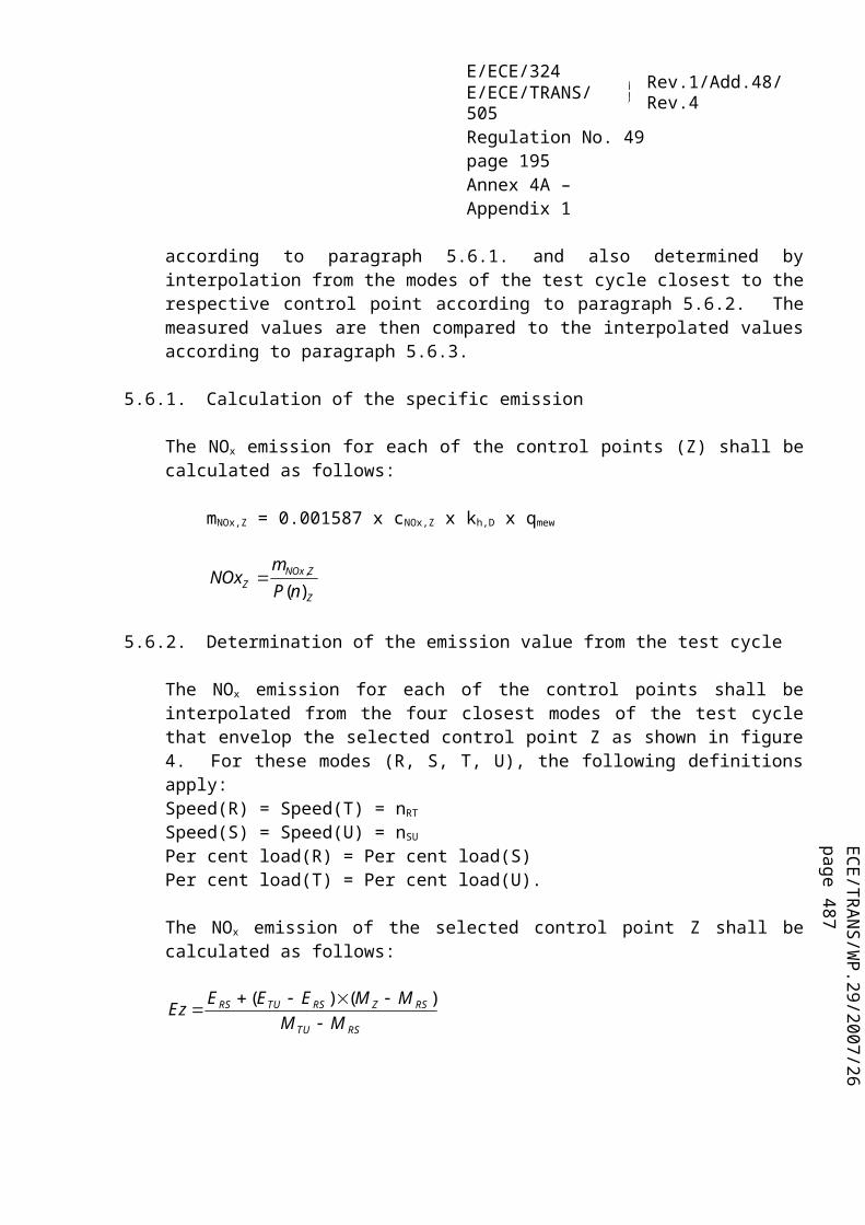
ECE/TR
AN
S/WP.29/2007/26
page 487
E/ECE/324E/ECE/TRANS/505 Rev.1/Add.48/Rev.4
Regulation No. 49page 195Annex 4A – Appendix 4
during all filter conditioning and weighing. The humidity shall be maintained to a dewpoint of 282.5 K ± 3 K (9.5 °C ± 3 °C) and a relative humidity of 45 per cent ± 8 per cent.
4.2.2. Reference filter weighing
The chamber (or room) environment shall be free of any ambient contaminants (such as dust) that would settle on the particulate filters during their stabilisation. Disturbances to weighing room specifications as outlined in paragraph 4.2.1. will be allowed if the duration of the disturbances does not exceed 30 minutes. The weighing room should meet the required specifications prior to personal entrance into the weighing room. At least two unused reference filters shall be weighed within 4 hours of, but preferably at the same time as the sample filter weightings. They shall be the same size and material as the sample filters.
If the average weight of the reference filters changes between sample filter weightings by more than 10 µg, then all sample filters shall be discarded and the emissions test repeated.
If the weighing room stability criteria outlined in paragraph 4.2.1. is not met, but the reference filter weightings meet the above criteria, the engine manufacturer has the option of accepting the sample filter weights or voiding the tests, fixing the weighing room control system and re-running the test.
4.2.3. Analytical balance
The analytical balance used to determine the filter weight shall have a precision (standard deviation) of at least 2 µg and a resolution of at least 1 µg (1 digit = 1 µg) specified by the balance manufacturer.
4.2.4. Elimination of static electricity effects
To eliminate the effects of static electricity, the filters shall be neutralized prior to weighing, e.g. by a Polonium neutralizer, a Faraday cage or a device of similar effect.
4.2.5. Specifications for flow measurement
4.2.5.1. General requirements
Absolute accuracies of flow meter or flow measurement instrumentation shall be as specified in paragraph 2.2.

E/ECE/324E/ECE/TRANS/505 Rev.1/Add.48/Rev.4
Regulation No. 49page 196Annex 4A – Appendix 4
4.2.5.2. Special provisions for partial flow dilution systems
For partial flow dilution systems, the accuracy of the sample flow qmp is of special concern, if not measured directly, but determined by differential flow measurement:
mdwmdew qq mpq
In this case an accuracy of 2 per cent for qmdew and qmdw is not sufficient to guarantee acceptable accuracies of qmp. If the gas flow is determined by differential flow measurement, the maximum error of the difference shall be such that the accuracy of qmp is within 5 per cent when the dilution ratio is less than 15. It can be calculated by taking root-mean-square of the errors of each instrument.
Acceptable accuracies of qmp can be obtained by either of the following methods:
The absolute accuracies of qmdew and qmdw are 0.2 per cent which guarantees an accuracy of qmp of 5 per cent at a dilution ratio of 15. However, greater errors will occur at higher dilution ratios;
Calibration of qmdw relative to qmdew is carried out such that the same accuracies for qmp as in a) are obtained. For the details of such a calibration see paragraph 3.2.1. of Appendix 5 to this annex;
The accuracy of qmp is determined indirectly from the accuracy of the dilution ratio as determined by a tracer gas, e.g. CO2. Again, accuracies equivalent to method a) for qmp are required;
The absolute accuracy of qmdew and qmdw is within 2 per cent of full scale, the maximum error of the difference between qmdew and qmdw is within 0.2 per cent, and the linearity error is within 0.2 per cent of the highest qmdew observed during the test.
5. DETERMINATION OF SMOKE
This paragraph provides specifications for the required and optional test equipment to be used for the ELR test. The smoke shall be measured with an opacimeter having an opacity and a light absorption coefficient readout mode. The opacity readout mode shall only be used for calibration and checking of the opacimeter. The smoke values of the test cycle shall be measured in the light absorption coefficient readout mode.

ECE/TR
AN
S/WP.29/2007/26
page 487
E/ECE/324E/ECE/TRANS/505 Rev.1/Add.48/Rev.4
Regulation No. 49page 197Annex 4A – Appendix 4
5.1. General requirements
The ELR requires the use of a smoke measurement and data processing system which includes three functional units. These units may be integrated into a single component or provided as a system of interconnected components. The three functional units are:(a) An opacimeter meeting the specifications of Appendix 7, paragraph 3.(b) A data processing unit capable of performing the functions described in
paragraph 7. of Appendix 1 to this annex.(c) A printer and/or electronic storage medium to record and output the required
smoke values specified in paragraph 7.3. of Appendix 1 to this annex.
5.2. Specific requirements
5.2.1. Linearity
The linearity shall be within ± 2 per cent opacity.
5.2.2. Zero Drift
The zero drift during a one hour period shall not exceed ± 1 per cent opacity.
5.2.3. Opacimeter Display and Range
For display in opacity, the range shall be 0-100 per cent opacity, and the readability 0.1 per cent opacity. For display in light absorption coefficient, the range shall be 0-30 m−1 light absorption coefficient, and the readability 0.01 m−1 light absorption coefficient.
5.2.4. Instrument response time
The physical response time of the opacimeter shall not exceed 0.2 s. The physical response time is the difference between the times when the output of a rapid response receiver reaches 10 and 90 per cent of the full deviation when the opacity of the gas being measured is changed in less than 0.1 s.
The electrical response time of the opacimeter shall not exceed 0.05 s. The electrical response time is the difference between the times when the opacimeter output reaches 10 and 90 per cent of the full scale when the light source is interrupted or completely extinguished in less than 0.01 s.

E/ECE/324E/ECE/TRANS/505 Rev.1/Add.48/Rev.4
Regulation No. 49page 198Annex 4A – Appendix 4
5.2.5. Neutral density filters
Any neutral density filter used in conjunction with opacimeter calibration, linearity measurements, or setting span shall have its value known to within 1.0 per cent opacity. The filter's nominal value shall be checked for accuracy at least yearly using a reference traceable to a national or international standard.
Neutral density filters are precision devices and can easily be damaged during use. Handling should be minimized and, when required, should be done with care to avoid scratching or soiling of the filter.

ECE/TR
AN
S/WP.29/2007/26
page 487
E/ECE/324E/ECE/TRANS/505 Rev.1/Add.48/Rev.4
Regulation No. 49page 199Annex 4A – Appendix 5
Annex 4A - Appendix 5
CALIBRATION PROCEDURE
1. CALIBRATION OF THE ANALYTICAL INSTRUMENTS
1.1. Introduction
Each analyzer shall be calibrated as often as necessary to fulfil the accuracy requirements of this Regulation. The calibration method that shall be used is described in this paragraph for the analyzers indicated in Appendix 4, paragraph 3. and Appendix 7, paragraph 1.
1.2. Calibration Gases
The shelf life of all calibration gases shall be respected.The expiration date of the calibration gases stated by the manufacturer shall be recorded.
1.2.1. Pure Gases
The required purity of the gases is defined by the contamination limits given below. The following gases shall be available for operation:
Purified nitrogen(Contamination ≤ 1 ppm C1, ≤ 1 ppm CO, ≤ 400 ppm CO2, ≤ 0.1 ppm NO)Purified oxygen(Purity > 99.5 per cent vol O2)Hydrogen-helium mixture(40 ± 2 per cent hydrogen, balance helium)(Contamination ≤ 1 ppm C1, ≤ 400 ppm CO2)Purified synthetic air(Contamination ≤ 1 ppm C1, ≤ 1 ppm CO, ≤ 400 ppm CO2, ≤ 0,1 ppm NO)(Oxygen content between 18-21 per cent vol.)Purified propane or CO for the CVS verification
1.2.2. Calibration and Span Gases
Mixtures of gases having the following chemical compositions shall be available:C3H8 and purified synthetic air (see paragraph 1.2.1.);CO and purified nitrogen;NOx and purified nitrogen (the amount of NO2 contained in this calibration gas shall not exceed 5 per cent of the NO content);CO2 and purified nitrogen

E/ECE/324E/ECE/TRANS/505 Rev.1/Add.48/Rev.4
Regulation No. 49page 200Annex 4A – Appendix 5
CH4 and purified synthetic airC2H6 and purified synthetic air
Note: Other gas combinations are allowed provided the gases do not react with one another.
The true concentration of a calibration and span gas shall be within ± 2 per cent of the nominal value. All concentrations of calibration gas shall be given on a volume basis (volume percent or volume ppm).
The gases used for calibration and span may also be obtained by means of a gas divider, diluting with purified N2 or with purified synthetic air. The accuracy of the mixing device shall be such that the concentration of the diluted calibration gases may be determined to within ± 2 per cent.
1.2.3. Use of precision blending devices
The gases used for calibration and span may also be obtained by means of precision blending devices (gas dividers), diluting with purified N2 or with purified synthetic air. The accuracy of the mixing device shall be such that the concentration of the blended calibration gases is accurate to within 2 per cent. This accuracy implies that primary gases used for blending shall be known to an accuracy of at least 1 per cent, traceable to national or international gas standards. The verification shall be performed at between 15 and 50 per cent of full scale for each calibration incorporating a blending device.
Optionally, the blending device may be checked with an instrument which by nature is linear, e.g. using NO gas with a CLD. The span value of the instrument shall be adjusted with the span gas directly connected to the instrument. The blending device shall be checked at the used settings and the nominal value shall be compared to the measured concentration of the instrument. This difference shall in each point be within 1 per cent of the nominal value.
1.3. Operating Procedure for Analyzers and Sampling System
The operating procedure for analyzers shall follow the start-up and operating instructions of the instrument manufacturer. The minimum requirements given in paragraphs 1.4 to 1.9 shall be included.
1.4. Leakage test
A system leakage test shall be performed. The probe shall be disconnected from the exhaust system and the end plugged. The analyzer pump shall be switched on. After an initial stabilisation period all flow meters should read zero. If not, the sampling lines shall be checked and the fault corrected.

ECE/TR
AN
S/WP.29/2007/26
page 487
E/ECE/324E/ECE/TRANS/505 Rev.1/Add.48/Rev.4
Regulation No. 49page 201Annex 4A – Appendix 5
The maximum allowable leakage rate on the vacuum side shall be 0.5 per cent of the in-use flow rate for the portion of the system being checked. The analyzer flows and bypass flows may be used to estimate the in-use flow rates.
Alternatively, the system may be evacuated to a pressure of at least 20 kPa vacuum (80 kPa absolute). After an initial stabilisation period the pressure increase p (kPa/min) in the system should not exceed:
p = p / Vs × 0.005 × qvs
where:Vs = system volume, lqvs = system flow rate, l/min
Another method is the introduction of a concentration step change at the beginning of the sampling line by switching from zero to span gas. If after an adequate period of time the reading is about 1 per cent low compared to the introduced concentration, these points to calibration or leakage problems.
1.5. Response time check of analytical system
The system settings for the response time evaluation shall be exactly the same as during measurement of the test run (i.e. pressure, flow rates, filter settings on the analyzers and all other response time influences). The response time determination shall be done with gas switching directly at the inlet of the sample probe. The gas switching shall be done in less than 0.1 second. The gases used for the test shall cause a concentration change of at least 60 per cent FS.
The concentration trace of each single gas component shall be recorded. The response time is defined to be the difference in time between the gas switching and the appropriate change of the recorded concentration. The system response time (t90) consists of the delay time to the measuring detector and the rise time of the detector. The delay time is defined as the time from the change (t0) until the response is 10 per cent of the final reading (t10). The rise time is defined as the time between 10 per cent and 90 per cent response of the final reading (t90 – t10).
For time alignment of the analyzer and exhaust flow signals in the case of raw measurement, the transformation time is defined as the time from the change (t0) until the response is 50 per cent of the final reading (t50).
The system response time shall be 10 seconds with a rise time 3.5 seconds for all limited components (CO, NOx, HC or NMHC) and all ranges used.

E/ECE/324E/ECE/TRANS/505 Rev.1/Add.48/Rev.4
Regulation No. 49page 202Annex 4A – Appendix 5
1.6. Calibration
1.6.1. Instrument assembly
The instrument assembly shall be calibrated and calibration curves checked against standard gases. The same gas flow rates shall be used as when sampling exhaust.
1.6.2. Warming-up time
The warming-up time should be according to the recommendations of the manufacturer. If not specified, a minimum of two hours is recommended for warming up the analyzers.
1.6.3. NDIR and HFID analyzer
The NDIR analyzer shall be tuned, as necessary, and the combustion flame of the HFID analyzer shall be optimised (paragraph 1.8.1.).
1.6.4. Establishment of the calibration curve(a) Each normally used operating range shall be calibrated;(b) Using purified synthetic air (or nitrogen), the CO, CO2, NOx and HC analyzers
shall be set at zero;(c) The appropriate calibration gases shall be introduced to the analyzers, the
values recorded, and the calibration curve established;(d) The calibration curve shall be established by at least 6 calibration points
(excluding zero) approximately equally spaced over the operating range. The highest nominal concentration shall be equal to or higher than 90 per cent of full scale;
(e) The calibration curve shall be calculated by the method of least-squares. A best-fit linear or non-linear equation may be used;
(f) The calibration points shall not differ from the least-squares best-fit line by more than ± 2 per cent of reading or ± 0.3 per cent of full scale whichever is larger;
(g) The zero setting shall be rechecked and the calibration procedure repeated, if necessary.
1.6.5. Alternative methods
If it can be shown that alternative technology (e.g. computer, electronically controlled range switch, etc.) can give equivalent accuracy, then these alternatives may be used.
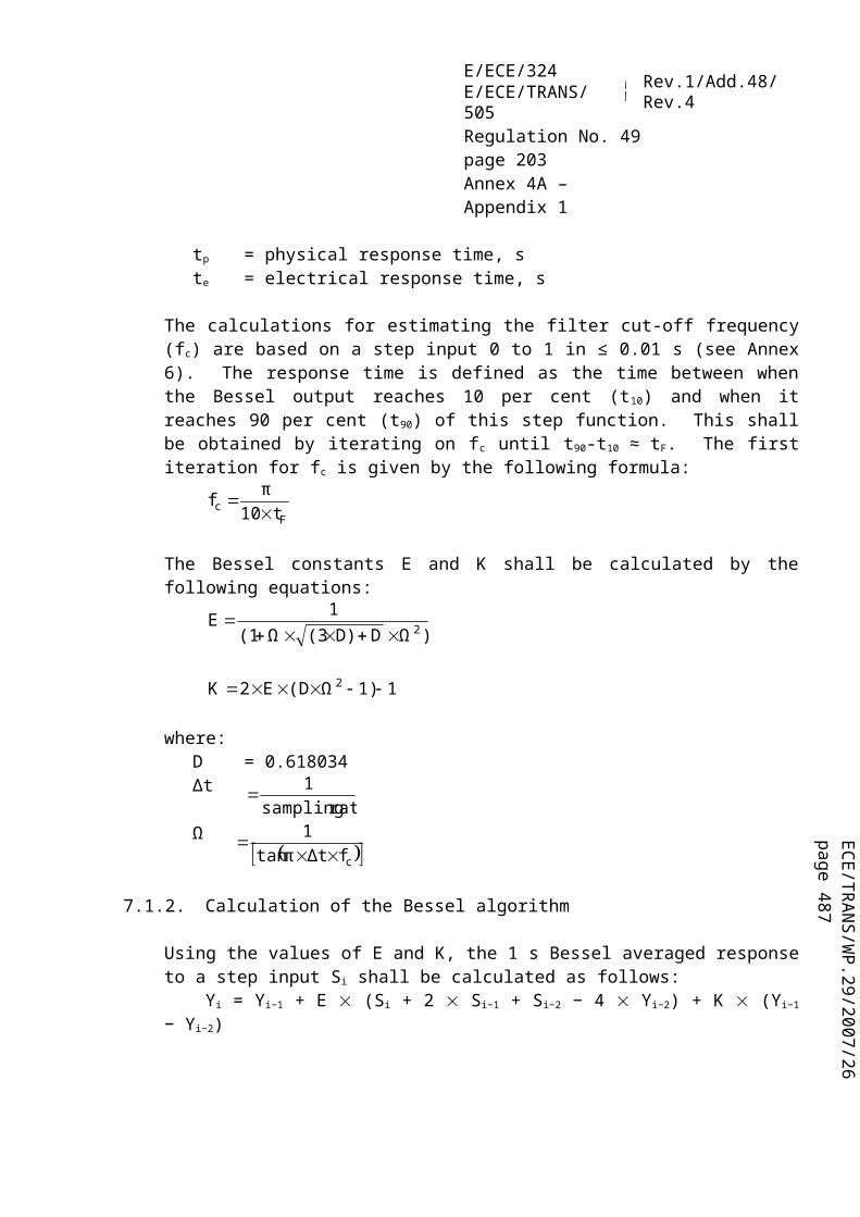
ECE/TR
AN
S/WP.29/2007/26
page 487
E/ECE/324E/ECE/TRANS/505 Rev.1/Add.48/Rev.4
Regulation No. 49page 203Annex 4A – Appendix 5
1.6.6. Calibration of tracer gas analyzer for exhaust flow measurement
The calibration curve shall be established by at least 6 calibration points (excluding zero) approximately equally spaced over the operating range. The highest nominal concentration shall be equal to or higher than 90 per cent of full scale. The calibration curve is calculated by the method of least squares.
The calibration points shall not differ from the least-squares best-fit line by more than ± 2 per cent of reading or ± 0.3 per cent of full scale whichever is larger.
The analyzer shall be set at zero and spanned prior to the test run using a zero gas and a span gas whose nominal value is more than 80 per cent of the analyzer full scale.
1.6.7. Verification of the calibration
Each normally used operating range shall be checked prior to each analysis in accordance with the following procedure.
The calibration shall be checked by using a zero gas and a span gas whose nominal value is more than 80 per cent of full scale of the measuring range.
If, for the two points considered, the value found does not differ by more than ± 4 per cent of full scale from the declared reference value, the adjustment parameters may be modified. Should this not be the case, a new calibration curve shall be established in accordance with paragraph 1.5.5.
1.7. Efficiency test of the NOx converter
The efficiency of the converter used for the conversion of NO2 into NO shall be tested as given in paragraphs 1.7.1. to 1.7.8. (figure 6).
1.7.1. Test set-up
Using the test set-up as shown in figure 6 (see also Appendix 4, paragraph 3.3.5. to this annex) and the procedure below, the efficiency of converters can be tested by means of an ozonator.
1.7.2. Calibration
The CLD and the HCLD shall be calibrated in the most common operating range following the manufacturer's specifications using zero and span gas (the NO content of which shall amount to about 80 per cent of the operating range and the NO2
concentration of the gas mixture to less than 5 per cent of the NO concentration).
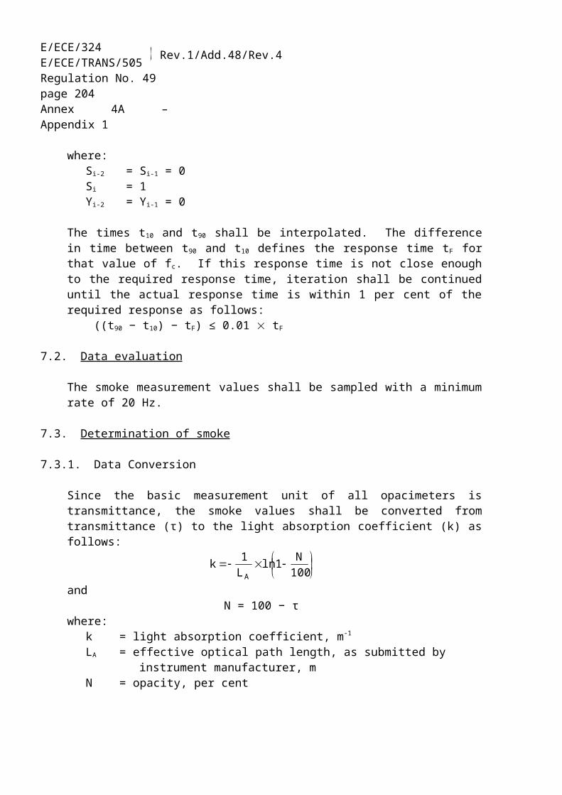
E/ECE/324E/ECE/TRANS/505 Rev.1/Add.48/Rev.4
Regulation No. 49page 204Annex 4A – Appendix 5
The NOx analyzer shall be in the NO mode so that the span gas does not pass through the converter. The indicated concentration has to be recorded.
1.7.3. Calculation
The efficiency of the NOx converter is calculated as follows:
100dcba1(%) Efficiency
where,a is the NOx concentration according to paragraph 1.7.6.b is the NOx concentration according to paragraph 1.7.7.c is the NO concentration according to paragraph 1.7.4.d is the NO concentration according to paragraph 1.7.5.
1.7.4. Adding of oxygen
Via a T-fitting, oxygen or zero air is added continuously to the gas flow until the concentration indicated is about 20 per cent less than the indicated calibration concentration given in paragraph 1.7.2. (the analyzer is in the NO mode). The indicated concentration c shall be recorded. The ozonator is kept deactivated throughout the process.
1.7.5. Activation of the ozonator
The ozonator is now activated to generate enough ozone to bring the NO concentration down to about 20 per cent (minimum 10 per cent) of the calibration concentration given in paragraph 1.7.2. The indicated concentration d shall be recorded (the analyzer is in the NO mode).
1.7.6. NOx mode
The NO analyzer is then switched to the NOx mode so that the gas mixture (consisting of NO, NO2, O2 and N2) now passes through the converter. The indicated concentration "a" shall be recorded (the analyzer is in the NOx mode).
1.7.7. Deactivation of the ozonator
The ozonator is now deactivated. The mixture of gases described in paragraph 1.7.6. passes through the converter into the detector. The indicated concentration b shall be recorded (the analyzer is in the NOx mode).

ECE/TR
AN
S/WP.29/2007/26
page 487
E/ECE/324E/ECE/TRANS/505 Rev.1/Add.48/Rev.4
Regulation No. 49page 205Annex 4A – Appendix 5
1.7.8. NO mode
Switched to NO mode with the ozonator deactivated, the flow of oxygen or synthetic air is also shut off. The NOx reading of the analyzer shall not deviate by more than ± 5 per cent from the value measured according to paragraph 1.7.2. (the analyzer is in the NO mode).
1.7.9. Test interval
The efficiency of the converter shall be tested prior to each calibration of the NOx
analyzer.
1.7.10. Efficiency requirement
The efficiency of the converter shall not be less than 90 per cent, but a higher efficiency of 95 per cent is strongly recommended.
Note: If, with the analyzer in the most common range, the ozonator cannot give a reduction from 80 per cent to 20 per cent according to paragraph 1.7.5., then the highest range which will give the reduction shall be used.
Figure 6Schematic of NOx converter efficiency device

E/ECE/324E/ECE/TRANS/505 Rev.1/Add.48/Rev.4
Regulation No. 49page 206Annex 4A – Appendix 5
1.8. Adjustment of the FID
1.8.1. Optimisation of the detector response
The FID shall be adjusted as specified by the instrument manufacturer. A propane in air span gas should be used to optimise the response on the most common operating range.
With the fuel and air flow rates set at the manufacturer's recommendations, a 350 ± 75 ppm C span gas shall be introduced to the analyzer. The response at a given fuel flow shall be determined from the difference between the span gas response and the zero gas response. The fuel flow shall be incrementally adjusted above and below the manufacturer's specification. The span and zero response at these fuel flows shall be recorded. The difference between the span and zero response shall be plotted and the fuel flow adjusted to the rich side of the curve.
1.8.2. Hydrocarbon response factors
The analyzer shall be calibrated using propane in air and purified synthetic air, according to paragraph 1.5.Response factors shall be determined when introducing an analyzer into service and after major service intervals. The response factor (Rf) for a particular hydrocarbon species is the ratio of the FID C1 reading to the gas concentration in the cylinder expressed by ppm C1.
The concentration of the test gas shall be at a level to give a response of approximately 80 per cent of full scale. The concentration shall be known to an accuracy of ± 2 per cent in reference to a gravimetric standard expressed in volume. In addition, the gas cylinder shall be preconditioned for 24 hours at a temperature of 298 K ± 5 K (25 °C ± 5 °C).
The test gases to be used and the recommended relative response factor ranges are as follows:
Methane and purified synthetic air 1.00 ≤ Rf ≤ 1.15Propylene and purified synthetic air 0.90 ≤ Rf ≤ 1.10Toluene and purified synthetic air 0.90 ≤ Rf ≤ 1.10
These values are relative to the response factor (Rf) of 1.00 for propane and purified synthetic air.

ECE/TR
AN
S/WP.29/2007/26
page 487
E/ECE/324E/ECE/TRANS/505 Rev.1/Add.48/Rev.4
Regulation No. 49page 207Annex 4A – Appendix 5
1.8.3. Oxygen interference check
The oxygen interference check shall be determined when introducing an analyzer into service and after major service intervals.
The response factor is defined and shall be determined as described in paragraph 1.8.2. The test gas to be used and the recommended relative response factor range are as follows:
Propane and nitrogen 0.95 ≤ Rf ≤ 1.05
This value is relative to the response factor (Rf) of 1.00 for propane and purified synthetic air.
The FID burner air oxygen concentration shall be within ± 1 mole per cent of the oxygen concentration of the burner air used in the latest oxygen interference check. If the difference is greater, the oxygen interference shall be checked and the analyzer adjusted, if necessary.
1.8.4. Efficiency of the non-methane cutter (NMC, for NG fuelled gas engines only)
The NMC is used for the removal of the non-methane hydrocarbons from the sample gas by oxidizing all hydrocarbons except methane. Ideally, the conversion for methane is 0 per cent, and for the other hydrocarbons represented by ethane is 100 per cent. For the accurate measurement of NMHC, the two efficiencies shall be determined and used for the calculation of the NMHC emission mass flow rate (see Annex 4A, Appendix 2, paragraph 5.4.).
1.8.4.1. Methane efficiency
Methane calibration gas shall be flown through the FID with and without bypassing the NMC and the two concentrations recorded. The efficiency shall be determined as follows:
where,cw = HC concentration with CH4 flowing through the NMCcw/o = HC concentration with CH4 bypassing the NMC

E/ECE/324E/ECE/TRANS/505 Rev.1/Add.48/Rev.4
Regulation No. 49page 208Annex 4A – Appendix 5
1.8.4.2. Ethane efficiency
Ethane calibration gas shall be flown through the FID with and without bypassing the NMC and the two concentrations recorded. The efficiency shall be determined as follows:
where,cw = HC concentration with C2H6 flowing through the NMCcw/o = HC concentration with C2H6 bypassing the NMC
1.9. Interference effects with CO, CO2, and NOx analyzers
Gases present in the exhaust other than the one being analysed can interfere with the reading in several ways. Positive interference occurs in NDIR instruments where the interfering gas gives the same effect as the gas being measured, but to a lesser degree. Negative interference occurs in NDIR instruments by the interfering gas broadening the absorption band of the measured gas, and in CLD instruments by the interfering gas quenching the radiation. The interference checks in paragraphs 1.9.1. and 1.9.2. shall be performed prior to an analyzer's initial use and after major service intervals.
1.9.1. CO analyzer interference check
Water and CO2 can interfere with the CO analyzer performance. Therefore, a CO2
span gas having a concentration of 80 to 100 per cent of full scale of the maximum operating range used during testing shall be bubbled through water at room temperature and the analyzer response recorded. The analyzer response shall not be more than 1 per cent of full scale for ranges equal to or above 300 ppm or more than 3 ppm for ranges below 300 ppm.
1.9.2. NOx analyzer quench checks
The two gases of concern for CLD (and HCLD) analyzers are CO2 and water vapour. Quench responses to these gases are proportional to their concentrations, and therefore require test techniques to determine the quench at the highest expected concentrations experienced during testing.
1.9.2.1. CO2 quench check
A CO2 span gas having a concentration of 80 to 100 per cent of full scale of the maximum operating range shall be passed through the NDIR analyzer and the CO2
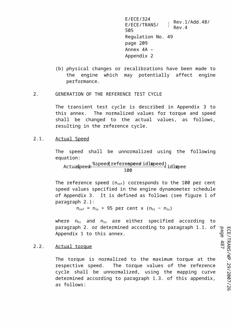
ECE/TR
AN
S/WP.29/2007/26
page 487
E/ECE/324E/ECE/TRANS/505 Rev.1/Add.48/Rev.4
Regulation No. 49page 209Annex 4A – Appendix 5
value recorded as A. It shall then be diluted approximately 50 per cent with NO span gas and passed through the NDIR and (H)CLD, with the CO2 and NO values recorded as B and C, respectively. The CO2 shall then be shut off and only the NO span gas be passed through the (H)CLD and the NO value recorded as D.
The quench, which shall not be greater than 3 per cent of full scale, shall be calculated as follows:
100BDAD
AC1Quench %
with:A is the undiluted CO2 concentration measured with NDIR in per centB is the diluted CO2 concentration measured with NDIR in per centC is the diluted NO concentration measured with (H)CLD in ppmD is the undiluted NO concentration measured with (H)CLD in ppm
Alternative methods of diluting and quantifying of CO2 and NO span gas values such as dynamic mixing/blending can be used.
1.9.2.2. Water quench check
This check applies to wet gas concentration measurements only. Calculation of water quench shall consider dilution of the NO span gas with water vapour and scaling of water vapour concentration of the mixture to that expected during testing.
A NO span gas having a concentration of 80 to 100 per cent of full scale of the normal operating range shall be passed through the (H)CLD and the NO value recorded as D. The NO span gas shall then be bubbled through water at room temperature and passed through the (H)CLD and the NO value recorded as C. The analyzer's absolute operating pressure and the water temperature shall be determined and recorded as E and F, respectively. The mixture's saturation vapour pressure that corresponds to the bubbler water temperature F shall be determined and recorded as G. The water vapour concentration (H, in per cent) of the mixture shall be calculated as follows:
H = 100 (G/E)
The expected diluted NO span gas (in water vapour) concentration (De) shall be calculated as follows:
De = D (1 − H/100)
For diesel exhaust, the maximum exhaust water vapour concentration (Hm, in per cent) expected during testing shall be estimated, under the assumption of a fuel atom

E/ECE/324E/ECE/TRANS/505 Rev.1/Add.48/Rev.4
Regulation No. 49page 210Annex 4A – Appendix 5
H/C ratio of 1.8:1, from the undiluted CO2 span gas concentration (A, as measured in paragraph 1.9.2.1.) as follows:
Hm = 0.9 A
The water quench, which shall not be greater than 3 per cent, shall be calculated as follows:
per cent quench = 100 ((De − C)/De) (Hm/H)
where,De = is the expected diluted NO concentration in ppmC = is the diluted NO concentration in ppmHm = is the maximum water vapour concentration in per centH = is the actual water vapour concentration in per cent
Note: It is important that the NO span gas contains minimal NO2 concentration for this check, since absorption of NO2 in water has not been accounted for in the quench calculations.
1.10. Calibration intervals
The analyzers shall be calibrated according to paragraph 1.6. at least every 3 months or whenever a system repair or change is made that could influence calibration.
2. CALIBRATION OF THE CVS-SYSTEM
2.1. General
The CVS system shall be calibrated by using an accurate flowmeter traceable to national or international standards and a restricting device. The flow through the system shall be measured at different restriction settings, and the control parameters of the system shall be measured and related to the flow.
Various types of flowmeters may be used, e.g. calibrated venturi, calibrated laminar flowmeter, calibrated turbinemeter.
2.2. Calibration of the positive displacement pump (PDP)
All parameters related to the pump shall be simultaneously measured with the parameters related to the flowmeter which is connected in series with the pump. The calculated flow rate (in m3/min at pump inlet, absolute pressure and temperature) shall be plotted versus a correlation function which is the value of a specific combination of pump parameters. The linear equation which relates the pump flow

ECE/TR
AN
S/WP.29/2007/26
page 487
E/ECE/324E/ECE/TRANS/505 Rev.1/Add.48/Rev.4
Regulation No. 49page 211Annex 4A – Appendix 5
and the correlation function shall then be determined. If a CVS has a multiple speed drive, the calibration shall be performed for each range used. Temperature stability shall be maintained during calibration.
2.2.1. Data analysis
The air flowrate (Qs) at each restriction setting (minimum 6 settings) shall be calculated in standard m3/min from the flowmeter data using the manufacturer's prescribed method. The air flow rate shall then be converted to pump flow (V0) in m3/rev at absolute pump inlet temperature and pressure as follows:
where,qvCVS = air flow rate at standard conditions (101.3 kPa, 273 K), m3/sT = temperature at pump inlet, Kpp = absolute pressure at pump inlet (pB-p1), kPan = pump speed, rev/s
To account for the interaction of pressure variations at the pump and the pump slip rate, the correlation function (X0) between pump speed, pressure differential from pump inlet to pump outlet and absolute pump outlet pressure shall be calculated as follows:
where,Δpp pressure differential from pump inlet to pump outlet, kPapp absolute outlet pressure at pump outlet, kPa
A linear least-square fit shall be performed to generate the calibration equation as follows:
D0 and m are the intercept and slope constants, respectively, describing the regression lines.
For a CVS system with multiple speeds, the calibration curves generated for the different pump flow ranges shall be approximately parallel, and the intercept values (D0) shall increase as the pump flow range decreases.
The calculated values from the equation shall be within ± 0.5 per cent of the measured value of V0. Values of m will vary from one pump to another. Particulate

E/ECE/324E/ECE/TRANS/505 Rev.1/Add.48/Rev.4
Regulation No. 49page 212Annex 4A – Appendix 5
influx over time will cause the pump slip to decrease, as reflected by lower values for m. Therefore, calibration shall be performed at pump start-up, after major maintenance, and if the total system verification (paragraph 2.4.) indicates a change of the slip rate.
2.3. Calibration of the critical flow venturi (CFV)
Calibration of the CFV is based upon the flow equation for a critical venturi. Gas flow is a function of inlet pressure and temperature.
2.3.1. Data analysis
The air flowrate (Qs) at each restriction setting (minimum 8 settings) shall be calculated in standard m3/min from the flowmeter data using the manufacturer's prescribed method. The calibration coefficient shall be calculated from the calibration data for each setting as follows:
where,qvCVS = air flow rate at standard conditions (101.3 kPa, 273 K), m3/sT = temperature at the venturi inlet, Kpp = absolute pressure at venturi inlet, kPa
To determine the range of critical flow, Kv shall be plotted as a function of venturi inlet pressure. For critical (choked) flow, Kv will have a relatively constant value. As pressure decreases (vacuum increases), the venturi becomes unchoked and Kv
decreases, which indicates that the CFV is operated outside the permissible range.
For a minimum of eight points in the region of critical flow, the average K v and the standard deviation shall be calculated. The standard deviation shall notexceed ± 0.3 per cent of the average KV.
2.4. Calibration of the subsonic venturi (SSV)
Calibration of the SSV is based upon the flow equation for a subsonic venturi. Gas flow is a function of inlet pressure and temperature, pressure drop between the SSV inlet and throat.
2.4.1. Data analysis
The air flowrate (QSSV) at each restriction setting (minimum 16 settings) shall be calculated in standard m3/min from the flowmeter data using the manufacturer's prescribed method. The discharge coefficient shall be calculated from the calibration

ECE/TR
AN
S/WP.29/2007/26
page 487
E/ECE/324E/ECE/TRANS/505 Rev.1/Add.48/Rev.4
Regulation No. 49page 213Annex 4A – Appendix 5
data for each setting as follows:
1.4286p
4D
1.7143p
1.4286ppd
2 11rr
rrT
pCdAQSSV1
0
where:QSSV = air flow rate at standard conditions (101.3 kPa, 273 K), m3/sT = temperature at the venturi inlet, Kd = diameter of the SSV throat, m
rp = ratio of the SSV throat to inlet absolute, static pressure =
rD = ratio of the SSV throat diameter, d, to the inlet pipe inner diameter D
To determine the range of subsonic flow, Cd shall be plotted as a function of Reynolds number at the SSV throat. The Re at the SSV throat is calculated with the following formula:
dSSVQ
A1Re
where:A1 = a collection of constants and units conversions
= 25.55152
QSSV = air flow rate at standard conditions (101.3 kPa, 273 K), m3/sd = diameter of the SSV throat, mμ = absolute or dynamic viscosity of the gas, calculated with the
following formula:
kg/m-s
b = empirical constant = 1.458 x 10⁶, kg/ms K0.5
S = empirical constant = 110.4 K
Because QSSV is an input to the Re formula, the calculations shall be started with an initial guess for QSSV or Cd of the calibration venturi, and repeated until QSSV
converges. The convergence method shall be accurate to 0.1 per cent of point or better.
For a minimum of sixteen points in the region of subsonic flow, the calculated values of Cd from the resulting calibration curve fit equation shall be within ± 0.5 per cent of the measured Cd for each calibration point.

E/ECE/324E/ECE/TRANS/505 Rev.1/Add.48/Rev.4
Regulation No. 49page 214Annex 4A – Appendix 5
2.5. Total system verification
The total accuracy of the CVS sampling system and analytical system shall be determined by introducing a known mass of a pollutant gas into the system while it is being operated in the normal manner. The pollutant is analysed, and the mass calculated according to Annex 4A, Appendix 2, paragraph 4.3. except in the case of propane where a factor of 0.000472 is used in place of 0.000479 for HC. Either of the following two techniques shall be used.
2.5.1. Metering with a critical flow orifice
A known quantity of pure gas (carbon monoxide or propane) shall be fed into the CVS system through a calibrated critical orifice. If the inlet pressure is high enough, the flow rate, which is adjusted by means of the critical flow orifice, is independent of the orifice outlet pressure (≡ critical flow). The CVS system shall be operated as in a normal exhaust emission test for about 5 to 10 minutes. A gas sample shall be analysed with the usual equipment (sampling bag or integrating method), and the mass of the gas calculated. The mass so determined shall be within ± 3 per cent of the known mass of the gas injected.
2.5.2. Metering by means of a gravimetric technique
The weight of a small cylinder filled with carbon monoxide or propane shall be determined with a precision of ± 0.01 gram. For about 5 to 10 minutes, the CVS system shall be operated as in a normal exhaust emission test, while carbon monoxide or propane is injected into the system. The quantity of pure gas discharged shall be determined by means of differential weighing. A gas sample shall be analysed with the usual equipment (sampling bag or integrating method), and the mass of the gas calculated. The mass so determined shall be within ± 3 per cent of the known mass of the gas injected.
3. CALIBRATION OF THE PARTICULATE MEASURING SYSTEM
3.1. Introduction
The calibration of the particulate measurement is limited to the flow meters used to determine sample flow and dilution ratio. Each flow meter shall be calibrated as often as necessary to fulfil the accuracy requirements of this Regulation. The calibration method that shall be used is described in paragraph 3.2.

ECE/TR
AN
S/WP.29/2007/26
page 487
E/ECE/324E/ECE/TRANS/505 Rev.1/Add.48/Rev.4
Regulation No. 49page 215Annex 4A – Appendix 5
3.2. Flow measurement
3.2.1. Periodical calibration
(a) To fulfil the absolute accuracy of the flow measurements as specified in paragraph 2.2. of Appendix 4 to this annex, the flow meter or the flow measurement instrumentation shall be calibrated with an accurate flow meter traceable to international and/or national standards.
(b) If the sample gas flow is determined by differential flow measurement the flow meter or the flow measurement instrumentation shall be calibrated in one of the following procedures, such that the probe flow qmp into the tunnel shall fulfil the accuracy requirements of paragraph 4.2.5.2. of Appendix 4 to this annex:(i) The flow meter for qmdw shall be connected in series to the flow meter for
qmdew, the difference between the two flow meters shall be calibrated for at least 5 set points with flow values equally spaced between the lowest qmdw value used during the test and the value of qmdew used during the test. The dilution tunnel may be bypassed.
(ii) A calibrated mass flow device shall be connected in series to the flowmeter for qmdew and the accuracy shall be checked for the value used for the test. Then the calibrated mass flow device shall be connected in series to the flow meter for qmdw, and the accuracy shall be checked for at least 5 settings corresponding to dilution ratio between 3 and 50, relative to qmdew used during the test.
(iii) The transfer tube TT shall be disconnected from the exhaust, and a calibrated flow measuring device with a suitable range to measure qmp
shall be connected to the transfer tube. Then qmdew shall be set to the value used during the test, and qmdw shall be sequentially set to at least 5 values corresponding to dilution ratios q between 3 and 50. Alternatively, a special calibration flow path, may be provided, in which the tunnel is bypassed, but the total and dilution air flow through the corresponding meters as in the actual test.
(iv) A tracer gas, shall be fed into the exhaust transfer tube TT. This tracer gas may be a component of the exhaust gas, like CO2 or NOx. After dilution in the tunnel the tracer gas component shall be measured. This shall be carried out for 5 dilution ratios between 3 and 50. The accuracy of the sample flow shall be determined from the dilution ratio rd:
d
mdew
rq
mpq
(c) The accuracies of the gas analyzers shall be taken into account to guarantee the accuracy of qmp.

E/ECE/324E/ECE/TRANS/505 Rev.1/Add.48/Rev.4
Regulation No. 49page 216Annex 4A – Appendix 5
3.2.2. Carbon flow check
(a) A carbon flow check using actual exhaust is recommended for detecting measurement and control problems and verifying the proper operation of the partial flow system. The carbon flow check should be run at least each time a new engine is installed, or something significant is changed in the test cell configuration.
(b) The engine shall be operated at peak torque load and speed or any other steady state mode that produces 5 per cent or more of CO2. The partial flow sampling system shall be operated with a dilution factor of about 15 to 1.
(c) If a carbon flow check is conducted, the procedure given in Appendix 6 to this annex shall be applied. The carbon flow rates shall be calculated according to paragraphs 2.1. to 2.3. of Appendix 6 to this annex. All carbon flow rates should agree to within 6 per cent of each other.
3.2.3. Pre-test check
(a) A pre-test check shall be performed within 2 hours before the test run in the following way:
(b) The accuracy of the flow meters shall be checked by the same method as used for calibration (see paragraph 3.2.1. of this appendix) for at least two points, including flow values of qmdw that correspond to dilution ratios between 5 and 15 for the qmdew value used during the test.
(c) If it can be demonstrated by records of the calibration procedure under paragraph 3.2.1. that the flow meter calibration is stable over a longer period of time, the pre-test check may be omitted.
3.3. Determination of transformation time (for partial flow dilution systems on ETC only)
(a) The system settings for the transformation time evaluation shall be exactly the same as during measurement of the test run. The transformation time shall be determined by the following method:
(b) An independent reference flowmeter with a measurement range appropriate for the probe flow shall be put in series with and closely coupled to the probe. This flowmeter shall have a transformation time of less than 100 ms for the flow step size used in the response time measurement, with flow restriction sufficiently low as to not affect the dynamic performance of the partial flow dilution system, and consistent with good engineering practice.
(c) A step change shall be introduced to the exhaust flow (or air flow if exhaust flow is calculated) input of the partial flow dilution system, from a low flow to at least 90 per cent of full scale. The trigger for the step change should be the same one used to start the look-ahead control in actual testing. The exhaust flow step stimulus and the flowmeter response shall be recorded at a sample rate of at least 10 Hz.

ECE/TR
AN
S/WP.29/2007/26
page 487
E/ECE/324E/ECE/TRANS/505 Rev.1/Add.48/Rev.4
Regulation No. 49page 217Annex 4A – Appendix 5
(d) From this data, the transformation time shall be determined for the partial flow dilution system, which is the time from the initiation of the step stimulus to the 50 per cent point of the flowmeter response. In a similar manner, the transformation times of the qmp signal of the partial flow dilution system and of the qmew,i signal of the exhaust flow meter shall be determined. These signals are used in the regression checks performed after each test (see paragraph 3.8.3.2. of Appendix 2 to this annex).
(e) The calculation shall be repeated for at least 5 rise and fall stimuli, and the results shall be averaged. The internal transformation time (< 100 msec) of the reference flowmeter shall be subtracted from this value. This is the "look-ahead" value of the partial flow dilution system, which shall be applied in accordance with paragraph 3.8.3.2. of Appendix 2 to this annex.
3.4. Checking the partial flow conditions
The range of the exhaust gas velocity and the pressure oscillations shall be checked and adjusted according to the requirements of paragraph 2.2.1. of Appendix 7 (EP), if applicable.
3.5. Calibration intervals
The flow measurement instrumentation shall be calibrated at least every 3 months or whenever a system repair or change is made that could influence calibration.
4. CALIBRATION OF THE SMOKE MEASUREMENT EQUIPMENT
4.1. Introduction
The opacimeter shall be calibrated as often as necessary to fulfil the accuracy requirements of this Regulation. The calibration method to be used is described in this paragraph for the components indicated in Appendix 4, paragraph 5 and Appendix 7, paragraph 3. to this annex.
4.2. Calibration procedure
4.2.1. Warming-up time
The opacimeter shall be warmed up and stabilised according to the manufacturer's recommendations. If the opacimeter is equipped with a purge air system to prevent sooting of the instrument optics, this system should also be activated and adjusted according to the manufacturer's recommendations.
E/ECE/324E/ECE/TRANS/505 Rev.1/Add.48/Rev.4
Regulation No. 49page 218Annex 4A – Appendix 5
4.2.2. Establishment of the linearity response
The linearity of the opacimeter shall be checked in the opacity readout mode as per the manufacturer's recommendations. Three neutral density filters of known transmittance, which shall meet the requirements of Appendix 4, paragraph 5.2.5. to this annex, shall be introduced to the opacimeter and the value recorded. The neutral density filters shall have nominal opacities of approximately 10 per cent, 20 per cent and 40 per cent.
The linearity shall not differ by more than ± 2 per cent opacity from the nominal value of the neutral density filter. Any non-linearity exceeding the above value shall be corrected prior to the test.
4.3. Calibration intervals
The opacimeter shall be calibrated according to paragraph 4.2.2. at least every 3 months or whenever a system repair or change is made that could influence calibration.

ECE/TR
AN
S/WP.29/2007/26
page 487
E/ECE/324E/ECE/TRANS/505 Rev.1/Add.48/Rev.4
Regulation No. 49page 219Annex 4A – Appendix 6
Annex 4A - Appendix 6
CARBON FLOW CHECK
1. INTRODUCTION
All but a tiny part of the carbon in the exhaust comes from the fuel, and all but a minimal part of this is manifest in the exhaust gas as CO2. This is the basis for a system verification check based on CO2 measurements.
The flow of carbon into the exhaust measurement systems is determined from the fuel flow rate. The flow of carbon at various sampling points in the emissions and particulate sampling systems is determined from the CO2 concentrations and gas flow rates at those points.
In this sense, the engine provides a known source of carbon flow, and observing the same carbon flow in the exhaust pipe and at the outlet of the partial flow PM sampling system verifies leak integrity and flow measurement accuracy. This check has the advantage that the components are operating under actual engine test conditions of temperature and flow.
The following diagram shows the sampling points at which the carbon flows shall be checked. The specific equations for the carbon flows at each of the sample points are given below.
Figure 7Measuring points for carbon flow check
Air Fuel
ENGINE
CO 2 RAW
CO 2 PFS
Partial Flow System
12
3

E/ECE/324E/ECE/TRANS/505 Rev.1/Add.48/Rev.4
Regulation No. 49page 220Annex 4A – Appendix 6
2. CALCULATIONS
2.1. Carbon flow rate into the engine (location 1)
The carbon mass flow rate into the engine for a fuel CHαOε is given by:
where:qmf = fuel mass flow rate, kg/s
2.2. Carbon flow rate in the raw exhaust (location 2)
The carbon mass flow rate in the exhaust pipe of the engine shall be determined from the raw CO2 concentration and the exhaust gas mass flow rate:
where:cCO2,r = wet CO2 concentration in the raw exhaust gas, per centcCO2,a = wet CO2 concentration in the ambient air, per cent (around 0.04 per cent)qmew = exhaust gas mass flow rate on wet basis, kg/sMre = molecular mass of exhaust gas
If CO2 is measured on a dry basis it shall be converted to a wet basis according to paragraph 5.2. of Appendix 1 to this annex.
2.3. Carbon flow rate in the dilution system (location 3)
The carbon flow rate shall be determined from the dilute CO2 concentration, the exhaust gas mass flow rate and the sample flow rate:
where:cCO2,d = wet CO2 concentration in the dilute exhaust gas at the outlet of the
dilution tunnel, per centcCO2,a = wet CO2 concentration in the ambient air, per cent (around 0.04 per cent)

ECE/TR
AN
S/WP.29/2007/26
page 487
E/ECE/324E/ECE/TRANS/505 Rev.1/Add.48/Rev.4
Regulation No. 49page 221Annex 4A – Appendix 6
qmdew = diluted exhaust gas mass flow rate on wet basis, kg/sqmew = exhaust gas mass flow rate on wet basis, kg/s (partial flow system only)qmp = sample flow of exhaust gas into partial flow dilution system, kg/s (partial
flow system only)Mre = molecular mass of exhaust gas
If CO2 is measured on a dry basis, it shall be converted to wet basis according to paragraph 5.2. of Appendix 1 to this annex.
2.4. The molecular mass (Mre) of the exhaust gas shall be calculated as follows:
where:qmf = fuel mass flow rate, kg/sqmaw = intake air mass flow rate on wet basis, kg/sHa = humidity of intake air, g water per kg dry airMra = molecular mass of dry intake air (= 28.9 g/mol), , , = molar ratios referring to a fuel C H O N S
Alternatively, the following molecular masses may be used:Mre (diesel) = 28.9 g/molMre (LPG) = 28.6 g/molMre (NG) = 28.3 g/mol

E/ECE/324E/ECE/TRANS/505 Rev.1/Add.48/Rev.4
Regulation No. 49page 222Annex 4A – Appendix 7
Annex 4A - Appendix 7
ANALYTICAL AND SAMPLING SYSTEMS
1. DETERMINATION OF THE GASEOUS EMISSIONS
1.1. Introduction
Paragraph 1.2. and figures 7 and 8 contain detailed descriptions of the recommended sampling and analysing systems. Since various configurations can produce equivalent results, exact conformance with figures 7 and 8 is not required. Additional components such as instruments, valves, solenoids, pumps, and switches may be used to provide additional information and co-ordinate the functions of the component systems. Other components which are not needed to maintain the accuracy on some systems, may be excluded if their exclusion is based upon good engineering judgement.
Figure 7Flow diagram of raw exhaust gas analysis system for CO, CO2, NOx, HC ESC only
zero gas
span gas
zero gas
span gas
zero gas
zero gasV1
V1
F1 F2
F1 F2
P
P
T1
T1
SP1
SP1
optional 2 sampling probes
EPT2 G1
HC
air fuel
vent
vent
vent
vent
vent
vent
vent
V2
R3
R1 R2
FL1
T5
B
V12 V11
V10CO
CO2
C
T3 G2
V4
V5
FL5
FL6
FL3
T4
G3
V12 V11
T5
V8
V6 V7 V9
R4
FL4
FL2
HSL1
HSL2
HSL1
SL
V3NO
R5
B
zero gas
span gas
zero gas
span gas
1.2. Description of the analytical system
An analytical system for the determination of the gaseous emissions in the raw (figure 7, ESC only) or diluted (figure 8, ETC and ESC) exhaust gas is described based on the use of:

ECE/TR
AN
S/WP.29/2007/26
page 487
E/ECE/324E/ECE/TRANS/505 Rev.1/Add.48/Rev.4
Regulation No. 49page 223Annex 4A – Appendix 7
(a) HFID analyzer for the measurement of hydrocarbons;(b) NDIR analyzers for the measurement of carbon monoxide and carbon dioxide;(c) HCLD or equivalent analyzer for the measurement of the oxides of nitrogen;The sample for all components may be taken with one sampling probe or with two sampling probes located in close proximity and internally split to the different analyzers. Care shall be taken that no condensation of exhaust components (including water and sulphuric acid) occurs at any point of the analytical system.
Figure 8Flow diagram of diluted exhaust gas analysis system for
CO, CO2, NOx, HC ETC, optional for ESC
zero gas
span gas
zero gas
span gas
zero gas
span gas
zero gas
span gas
zero gas
V1
F1 F2
F1 F2
P
P
T1
T1
SP2
SP3
T2 G1
HC
air fuel
vent
vent
vent
vent
vent
vent
vent
V2
R3
R1 R2
FL1
T5
B
V13 V12
V11CO
CO2
C
T3 G2
V4
V5
FL5
FL6
FL3
T4
G3
V9
V7 V8 V10
R4
FL4
FL2
HSL1
HSL2
HSL1
SL
V3NO
R5
V1
PSP
to PSS see figure 21
same plane
see fig. 21
BK
BKBG
DTsee fig. 20
V14
1.2.1. Components of figures 7 and 8
EP exhaust pipeExhaust gas sampling probe (figure 7 only)
A stainless steel straight closed end multi-hole probe is recommended. The inside diameter shall not be greater than the inside diameter of the sampling line. The wall

E/ECE/324E/ECE/TRANS/505 Rev.1/Add.48/Rev.4
Regulation No. 49page 224Annex 4A – Appendix 7
thickness of the probe shall not be greater than 1 mm. There shall be a minimum of 3 holes in 3 different radial planes sized to sample approximately the same flow. The probe shall extend across at least 80 per cent of the diameter of the exhaust pipe. One or two sampling probes may be used.
SP2 diluted exhaust gas HC sampling probe (figure 8 only)
The probe shall:(a) be defined as the first 254 mm to 762 mm of the heated sampling line HSL1;(b) have a 5 mm minimum inside diameter;(c) be installed in the dilution tunnel DT (see paragraph 2.3., figure 20) at a point
where the dilution air and exhaust gas are well mixed (i.e. approximately 10 tunnel diameters downstream of the point where the exhaust enters the dilution tunnel);
(d) be sufficiently distant (radially) from other probes and the tunnel wall so as to be free from the influence of any wakes or eddies;
(e) be heated so as to increase the gas stream temperature to 463 K ± 10 K (190 °C ± 10 °C) at the exit of the probe.
SP3 diluted exhaust gas CO, CO2, NOx sampling probe (figure 8 only)
The probe shall:(a) be in the same plane as SP 2;(b) be sufficiently distant (radially) from other probes and the tunnel wall so as to be
free from the influence of any wakes or eddies;(c) be heated and insulated over its entire length to a minimum temperature of 328 K
(55 °C) to prevent water condensation.
HSL1 heated sampling line
The sampling line provides a gas sample from a single probe to the split point(s) and the HC analyzer.
The sampling line shall:(a) have a 5 mm minimum and a 13,5 mm maximum inside diameter;(b) be made of stainless steel or PTFE;(c) maintain a wall temperature of 463 K ± 10 K (190 °C ± 10 °C) as measured at
every separately controlled heated section, if the temperature of the exhaust gas at the sampling probe is equal to or below 463 K (190 °C);
(d) maintain a wall temperature greater than 453 K (180 °C), if the temperature of the exhaust gas at the sampling probe is above 463 K (190 °C);
(e) maintain a gas temperature of 463 K ± 10 K (190 °C ± 10 °C) immediately before the heated filter F2 and the HFID.

ECE/TR
AN
S/WP.29/2007/26
page 487
E/ECE/324E/ECE/TRANS/505 Rev.1/Add.48/Rev.4
Regulation No. 49page 225Annex 4A – Appendix 7
HSL2 heated NOx sampling line
The sampling line shall:(a) maintain a wall temperature of 328 K to 473 K (55 °C to 200 °C), up to the
converter C when using a cooling bath B, and up to the analyzer when a cooling bath B is not used.
(b) be made of stainless steel or PTFE.
SL sampling line for CO and CO2
The line shall be made of PTFE or stainless steel. It may be heated or unheated.
BK background bag (optional; figure 8 only)
For the sampling of the background concentrations.
BG sample bag (optional; figure 8 CO and CO2 only)
For the sampling of the sample concentrations.
F1 heated pre-filter (optional)
The temperature shall be the same as HSL1.
F2 Heated filter
The filter shall extract any solid particles from the gas sample prior to the analyzer. The temperature shall be the same as HSL1. The filter shall be changed as needed.
P heated sampling pump
The pump shall be heated to the temperature of HSL1.
HC
Heated flame ionisation detector (HFID) for the determination of the hydrocarbons. The temperature shall be kept at 453 K to 473 K (180 °C to 200 °C).
CO, CO2
NDIR analyzers for the determination of carbon monoxide and carbon dioxide (optional for the determination of the dilution ratio for PT measurement).

E/ECE/324E/ECE/TRANS/505 Rev.1/Add.48/Rev.4
Regulation No. 49page 226Annex 4A – Appendix 7
NO
CLD or HCLD analyzer for the determination of the oxides of nitrogen. If a HCLD is used it shall be kept at a temperature of 328 K to 473 K (55 °C to 200 °C).
C converter
A converter shall be used for the catalytic reduction of NO2 to NO prior to analysis in the CLD or HCLD.
B cooling bath (optional)
To cool and condense water from the exhaust sample. The bath shall be maintained at a temperature of 273 K to 277 K (0 °C to 4 °C) by ice or refrigeration. It is optional if the analyzer is free from water vapour interference as determined in paragraphs 1.9.1. and 1.9.2. of Appendix 5 to this annex. If water is removed by condensation, the sample gas temperature or dew point shall be monitored either within the water trap or downstream. The sample gas temperature or dew point shall not exceed 280 K (7 °C). Chemical dryers are not allowed for removing water from the sample.
T1, T2, T3 temperature sensor
To monitor the temperature of the gas stream.
T4 temperature sensor
To monitor the temperature of the NO2-NO converter.
T5 temperature sensor
To monitor the temperature of the cooling bath.
G1, G2, G3 pressure gauge
To measure the pressure in the sampling lines.
R1, R2 pressure regulator
To control the pressure of the air and the fuel, respectively, for the HFID.
R3, R4, R5 pressure regulator
To control the pressure in the sampling lines and the flow to the analyzers.

ECE/TR
AN
S/WP.29/2007/26
page 487
E/ECE/324E/ECE/TRANS/505 Rev.1/Add.48/Rev.4
Regulation No. 49page 227Annex 4A – Appendix 7
FL1, FL2, FL3 flowmeter
To monitor the sample by-pass flow rate.
FL4 to FL6 flowmeter (optional)
To monitor the flow rate through the analyzers.
V1 to V5 selector valve
Suitable valving for selecting sample, span gas or zero gas flow to the analyzers.
V6, V7 solenoid valve
To by-pass the NO2-NO converter.
V8 needle valve
To balance the flow through the NO2-NO converter C and the by-pass.
V9, V10 needle valve
To regulate the flows to the analyzers.
V11, V12 Toggle valve (optional)
To drain the condensate from the bath B.
1.3. NMHC analysis (NG fuelled gas engines only)
1.3.1. Gas chromatographic method (GC, figure 9)
When using the GC method, a small measured volume of a sample is injected onto an analytical column through which it is swept by an inert carrier gas. The column separates various components according to their boiling points so that they elute from the column at different times. They then pass through a detector which gives an electrical signal that depends on their concentration. Since it is not a continuous analysis technique, it can only be used in conjunction with the bag sampling method as described in paragraph 3.4.2. of Appendix 4 to this annex.
For NMHC an automated GC with a FID shall be used. The exhaust gas shall be sampled into a sampling bag from which a part shall be taken and injected into the GC. The sample is separated into two parts (CH4/Air/CO and NMHC/CO2/H2O) on the Porapak column. The molecular sieve column separates CH4 from the air and CO

E/ECE/324E/ECE/TRANS/505 Rev.1/Add.48/Rev.4
Regulation No. 49page 228Annex 4A – Appendix 7
before passing it to the FID where its concentration is measured. A complete cycle from injection of one sample to injection of a second can be made in 30 s. To determine NMHC, the CH4 concentration shall be subtracted from the total HC concentration (see paragraph 4.3.1. of Appendix 2 to this annex).
Figure 9 shows a typical GC assembled to routinely determine CH4. Other GC methods can also be used based on good engineering judgement.
Figure 9Flow diagram for methane analysis (GC method)
123456789
10
SLP
MSC
P
DF4 F1
V3
V2
V4
V6
V7
V8
F5
F3
R1
R2
R3
Oven
vent
F2
FM1
vent
to x
to yx
y10
V1
PC
sample span gas
fuel inlet
air inlet
HC
FC
Components of figure 9
PC Porapak column
Porapak N, 180/300 μm (50/80 mesh), 610 mm length × 2.16 mm ID shall be used and conditioned at least 12 h at 423 K (150 °C) with carrier gas prior to initial use.
MSC Molecular sieve column
Type 13X, 250/350 μm (45/60 mesh), 1220 mm length × 2.16 mm ID shall be used and conditioned at least 12 h at 423 K (150 °C) with carrier gas prior to initial use.

ECE/TR
AN
S/WP.29/2007/26
page 487
E/ECE/324E/ECE/TRANS/505 Rev.1/Add.48/Rev.4
Regulation No. 49page 229Annex 4A – Appendix 7
OV Oven
To maintain columns and valves at stable temperature for analyzer operation, and to condition the columns at 423 K (150 °C).
SLP Sample loop
A sufficient length of stainless steel tubing to obtain approximately 1 cm3 volume.
P Pump
To bring the sample to the gas chromatograph.
D Dryer
A dryer containing a molecular sieve shall be used to remove water and other contaminants which might be present in the carrier gas.
HC
Flame ionisation detector (FID) to measure the concentration of methane.
V1 Sample injection valve
To inject the sample taken from the sampling bag via SL of figure 8. It shall be low dead volume, gas tight, and heatable to 423 K (150 °C).
V3 Selector valve
To select span gas, sample, or no flow.
V2, V4, V5, V6, V7, V8 Needle valve
To set the flows in the system.
R1, R2, R3 Pressure regulator
To control the flows of the fuel (= carrier gas), the sample, and the air, respectively.
FC Flow capillary
To control the rate of air flow to the FID

E/ECE/324E/ECE/TRANS/505 Rev.1/Add.48/Rev.4
Regulation No. 49page 230Annex 4A – Appendix 7
G1, G2, G3 Pressure gauge
To control the flows of the fuel (= carrier gas), the sample, and the air, respectively.
F1, F2, F3, F4, F5 Filter
Sintered metal filters to prevent grit from entering the pump or the instrument.
FL1
To measure the sample by-pass flow rate.
1.3.2. Non-Methane Cutter Method (NMC, figure 10)
The cutter oxidizes all hydrocarbons except CH4 to CO2 and H2O, so that by passing the sample through the NMC only CH4 is detected by the FID. If bag sampling is used, a flow diverter system shall be installed at SL (see paragraph 1.2., figure 8) with which the flow can be alternatively passed through or around the cutter according to the upper part of figure 10. For NMHC measurement, both values (HC and CH4) shall be observed on the FID and recorded. If the integration method is used, an NMC in line with a second FID shall be installed parallel to the regular FID into HSL1 (see paragraph 1.2., figure 8) according to the lower part of figure 10. For NMHC measurement, the values of the two FID's (HC and CH4) shall be observed and recorded.
The cutter shall be characterized at or above 600 K (327 °C) prior to test work with respect to its catalytic effect on CH4 and C2H6 at H2O values representative of exhaust stream conditions. The dewpoint and O2 level of the sampled exhaust stream shall be known. The relative response of the FID to CH4 shall be recorded (see paragraph 1.8.2. of Appendix 5 to this annex).

ECE/TR
AN
S/WP.29/2007/26
page 487
E/ECE/324E/ECE/TRANS/505 Rev.1/Add.48/Rev.4
Regulation No. 49page 231Annex 4A – Appendix 7
Figure 10Flow diagram for methane analysis with the non-methane cutter (NMC)
zero
span
sample V1 V2 V3NMC
SL (see figure 8)
vent
HC
V4
zero
span
sample V1 V2NMC
HSL1 (see figure 8)
vent
HC
ventHC
Bag Sampling Method
Integrating Method
Components of figure 10
NMC Non-methane cutter
To oxidize all hydrocarbons except methane.
HC
Heated flame ionisation detector (HFID) to measure the HC and CH4 concentrations. The temperature shall be kept at 453 K to 473 K (180 °C to 200 °C).
V1 Selector valve
To select sample, zero and span gas. V1 is identical with V2 of figure 8.
V2, V3 Solenoid valve
To by-pass the NMC.
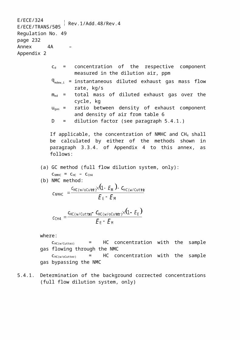
E/ECE/324E/ECE/TRANS/505 Rev.1/Add.48/Rev.4
Regulation No. 49page 232Annex 4A – Appendix 7
V4 Needle valve
To balance the flow through the NMC and the by-pass.
R1 Pressure regulator
To control the pressure in the sampling line and the flow to the HFID. R1 is identical with R3 of figure 8.
FL1 Flowmeter
To measure the sample by-pass flow rate. FL1 is identical with FL1 of figure 8.
2. EXHAUST GAS DILUTION AND DETERMINATION OF THE PARTICULATES
2.1. Introduction
Paragraphs 2.2., 2.3. and 2.4. and figures 11 to 22 contain detailed descriptions of the recommended dilution and sampling systems. Since various configurations can produce equivalent results, exact conformance with these figures is not required. Additional components such as instruments, valves, solenoids, pumps, and switches may be used to provide additional information and coordinate the functions of the component systems. Other components which are not needed to maintain the accuracy on some systems, may be excluded if their exclusion is based upon good engineering judgement.
2.2. Partial Flow Dilution System
A dilution system is described in figures 11 to 19 based upon the dilution of a part of the exhaust stream. Splitting of the exhaust stream and the following dilution process may be done by different dilution system types. For subsequent collection of the particulates, the entire dilute exhaust gas or only a portion of the dilute exhaust gas is passed to the particulate sampling system (paragraph 2.4., figure 21). The first method is referred to as total sampling type, the second method as fractional sampling type.
The calculation of the dilution ratio depends upon the type of system used. The following types are recommended:
Isokinetic systems (figures 11, 12)
With these systems, the flow into the transfer tube is matched to the bulk exhaust flow in terms of gas velocity and/or pressure, thus requiring an undisturbed and uniform exhaust flow at the sampling probe. This is usually achieved by using a resonator and a straight approach tube upstream of the sampling point. The split ratio is then calculated from easily measurable values like tube diameters. It should be noted that isokinesis is

ECE/TR
AN
S/WP.29/2007/26
page 487
E/ECE/324E/ECE/TRANS/505 Rev.1/Add.48/Rev.4
Regulation No. 49page 233Annex 4A – Appendix 7
only used for matching the flow conditions and not for matching the size distribution. The latter is typically not necessary, as the particles are sufficiently small as to follow the fluid streamlines.
Flow controlled systems with concentration measurement (figures 13 to 17)
With these systems, a sample is taken from the bulk exhaust stream by adjusting the dilution air flow and the total dilute exhaust flow. The dilution ratio is determined from the concentrations of tracer gases, such as CO2 or NOx naturally occurring in the engine exhaust. The concentrations in the dilute exhaust gas and in the dilution air are measured, whereas the concentration in the raw exhaust gas can be either measured directly or determined from fuel flow and the carbon balance equation, if the fuel composition is known. The systems may be controlled by the calculated dilution ratio (figures 13 and 14) or by the flow into the transfer tube (figures 12, 13 and 14).
Flow controlled systems with flow measurement (figures 18 and 19)
With these systems, a sample is taken from the bulk exhaust stream by setting the dilution air flow and the total dilute exhaust flow. The dilution ratio is determined from the difference of the two flows rates. Accurate calibration of the flow meters relative to one another is required, since the relative magnitude of the two flow rates can lead to significant errors at higher dilution ratios (of 15 and above). Flow control is very straight forward by keeping the dilute exhaust flow rate constant and varying the dilution air flow rate, if needed.
When using partial flow dilution systems, attention shall be paid to avoiding the potential problems of loss of particulates in the transfer tube, ensuring that a representative sample is taken from the engine exhaust, and determination of the split ratio. The systems described pay attention to these critical areas.

E/ECE/324E/ECE/TRANS/505 Rev.1/Add.48/Rev.4
Regulation No. 49page 234Annex 4A – Appendix 7
Figure 11Partial flow dilution system with isokinetic probe and fractional sampling (SB control)
see figure 21
DAF
EP
TT
DT
dPSP
PB FM1
ISP
FC1
l > 10*d
air
exhaust
PTT
to particulatesamplingsystem
SB
vent
DPTdelta p
Raw exhaust gas is transferred from the exhaust pipe EP to the dilution tunnel DT through the transfer tube TT by the isokinetic sampling probe ISP. The differential pressure of the exhaust gas between exhaust pipe and inlet to the probe is measured with the pressure transducer DPT. This signal is transmitted to the flow controller FC1 that controls the suction blower SB to maintain a differential pressure of zero at the tip of the probe. Under these conditions, exhaust gas velocities in EP and ISP are identical, and the flow through ISP and TT is a constant fraction (split) of the exhaust gas flow. The split ratio is determined from the cross sectional areas of EP and ISP. The dilution air flow rate is measured with the flow measurement device FM1. The dilution ratio is calculated from the dilution air flow rate and the split ratio.

ECE/TR
AN
S/WP.29/2007/26
page 487
E/ECE/324E/ECE/TRANS/505 Rev.1/Add.48/Rev.4
Regulation No. 49page 235Annex 4A – Appendix 7
Figure 12Partial flow dilution system with isokinetic probe and fractional sampling (PB control)
DAF
EP
TT DT
d
PB
FM1
ISP
delta p FC1DPT
l > 10*d
air
exhaust
PSP
PTT
see figure 21 to particulatesamplingsystem
ventSB
Raw exhaust gas is transferred from the exhaust pipe EP to the dilution tunnel DT through the transfer tube TT by the isokinetic sampling probe ISP. The differential pressure of the exhaust gas between exhaust pipe and inlet to the probe is measured with the pressure transducer DPT. This signal is transmitted to the flow controller FC1 that controls the pressure blower PB to maintain a differential pressure of zero at the tip of the probe. This is done by taking a small fraction of the dilution air whose flow rate has already been measured with the flow measurement device FM1, and feeding it to TT by means of a pneumatic orifice. Under these conditions, exhaust gas velocities in EP and ISP are identical, and the flow through ISP and TT is a constant fraction (split) of the exhaust gas flow. The split ratio is determined from the cross sectional areas of EP and ISP. The dilution air is sucked through DT by the suction blower SB, and the flow rate is measured with FM1 at the inlet to DT. The dilution ratio is calculated from the dilution air flow rate and the split ratio.

E/ECE/324E/ECE/TRANS/505 Rev.1/Add.48/Rev.4
Regulation No. 49page 236Annex 4A – Appendix 7
Figure 13Partial flow dilution system with CO2 or NOx concentration measurement
and fractional sampling
DAF
EP
SP
TT
DT
d
PB
l > 10*d
EGA EGA
EGA
air
exhaust
see figure 21 to particulatesamplingsystem
PSP
PTT
SB
vent
optionalto PB or SB
FC2
Raw exhaust gas is transferred from the exhaust pipe EP to the dilution tunnel DT through the sampling probe SP and the transfer tube TT. The concentrations of a tracer gas (CO2 or NOx) are measured in the raw and diluted exhaust gas as well as in the dilution air with the exhaust gas analyzer(s) EGA. These signals are transmitted to the flow controller FC2 that controls either the pressure blower PB or the suction blower SB to maintain the desired exhaust split and dilution ratio in DT. The dilution ratio is calculated from the tracer gas concentrations in the raw exhaust gas, the diluted exhaust gas, and the dilution air.
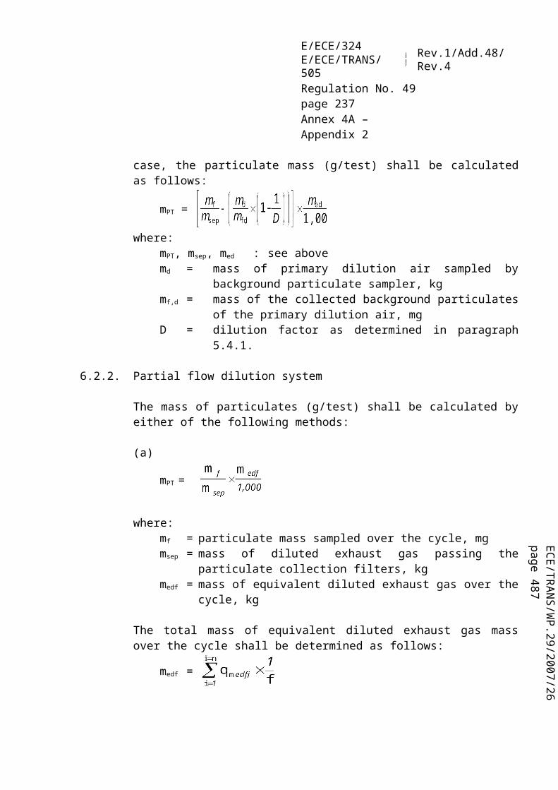
ECE/TR
AN
S/WP.29/2007/26
page 487
E/ECE/324E/ECE/TRANS/505 Rev.1/Add.48/Rev.4
Regulation No. 49page 237Annex 4A – Appendix 7
Figure 14Partial flow dilution system with CO2 concentration measurement,
carbon balance and total sampling
DAF
EP
SP
TT
DT
d
PB
EGA EGA
G FUEL
exhaust
air
PTT
details see figure 21
FH
P
optional to P
PSS
optional from FC2
FC2
Raw exhaust gas is transferred from the exhaust pipe EP to the dilution tunnel DT through the sampling probe SP and the transfer tube TT. The CO2 concentrations are measured in the diluted exhaust gas and in the dilution air with the exhaust gas analyzer(s) EGA. The CO2 and fuel flow GFUEL signals are transmitted either to the flow controller FC2, or to the flow controller FC3 of the particulate sampling system (see figure 21). FC2 controls the pressure blower PB, FC3 the sampling pump P (see figure 21), thereby adjusting the flows into and out of the system so as to maintain the desired exhaust split and dilution ratio in DT. The dilution ratio is calculated from the CO2
concentrations and GFUEL using the carbon balance assumption.

E/ECE/324E/ECE/TRANS/505 Rev.1/Add.48/Rev.4
Regulation No. 49page 238Annex 4A – Appendix 7
Figure 15Partial flow dilution system with single venturi,
concentration measurement and fractional sampling
DAF
EP
SP
TT
DT
d
PB l > 10*d
EGA
EGA
air
exhaust
EGA
see figure 21 to particulatesamplingsystem
ventPSP
PTT
VN
Raw exhaust gas is transferred from the exhaust pipe EP to the dilution tunnel DT through the sampling probe SP and the transfer tube TT due to the negative pressure created by the venturi VN in DT. The gas flow rate through TT depends on the momentum exchange at the venturi zone, and is therefore affected by the absolute temperature of the gas at the exit of TT. Consequently, the exhaust split for a given tunnel flow rate is not constant, and the dilution ratio at low load is slightly lower than at high load. The tracer gas concentrations (CO2 or NOx) are measured in the raw exhaust gas, the diluted exhaust gas, and the dilution air with the exhaust gas analyzer(s) EGA, and the dilution ratio is calculated from the values so measured.
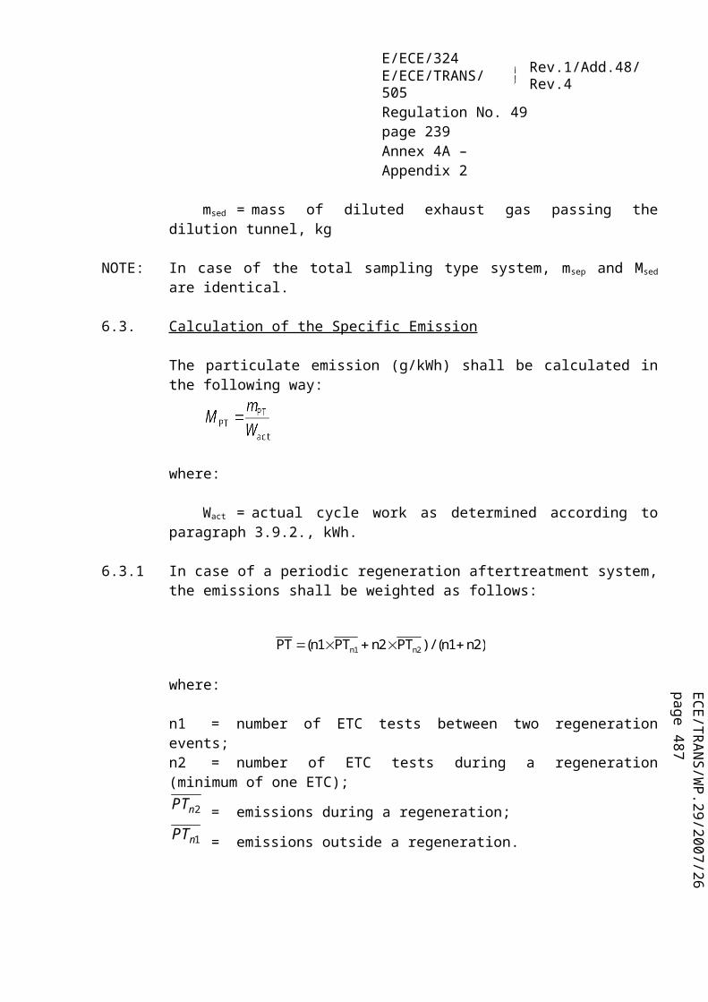
ECE/TR
AN
S/WP.29/2007/26
page 487
E/ECE/324E/ECE/TRANS/505 Rev.1/Add.48/Rev.4
Regulation No. 49page 239Annex 4A – Appendix 7
Figure 16Partial flow dilution system with twin venturi or twin orifice,
concentration measurement and fractional sampling
DAF
TT
DT
d
PB
l > 10*d
EGA
EGA
PCV1
PCV2 HE
EP
air
exhaust
PSP
EGA
PTTsee figure 21 to particulate
samplingsystem
vent
SB
FD1FD2
Raw exhaust gas is transferred from the exhaust pipe EP to the dilution tunnel DT through the sampling probe SP and the transfer tube TT by a flow divider that contains a set of orifices or venturis. The first one (FD1) is located in EP, the second one (FD2) in TT. Additionally, two pressure control valves (PCV1 and PCV2) are necessary to maintain a constant exhaust split by controlling the backpressure in EP and the pressure in DT. PCV1 is located downstream of SP in EP, PCV2 between the pressure blower PB and DT. The tracer gas concentrations (CO2 or NOx) are measured in the raw exhaust gas, the diluted exhaust gas, and the dilution air with the exhaust gas analyzer(s) EGA. They are necessary for checking the exhaust split, and may be used to adjust PCV1 and PCV2 for precise split control. The dilution ratio is calculated from the tracer gas concentrations.

E/ECE/324E/ECE/TRANS/505 Rev.1/Add.48/Rev.4
Regulation No. 49page 240Annex 4A – Appendix 7
Figure 17Partial flow dilution system with multiple tube splitting,
concentration measurement and fractional sampling
DAF
DT d
l > 10*d
EGA
HE
EGA
DPT
EP
TTDAF
air
air
fresh air injection
PSP
see figure 21to particulate
samplingsystem
PTTSB
DC
FD3
FC1
EGA
vent
Raw exhaust gas is transferred from the exhaust pipe EP to the dilution tunnel DT through the transfer tube TT by the flow divider FD3 that consists of a number of tubes of the same dimensions (same diameter, length and bend radius) installed in EP. The exhaust gas through one of these tubes is lead to DT, and the exhaust gas through the rest of the tubes is passed through the damping chamber DC. Thus, the exhaust split is determined by the total number of tubes. A constant split control requires a differential pressure of zero between DC and the outlet of TT, which is measured with the differential pressure transducer DPT. A differential pressure of zero is achieved by injecting fresh air into DT at the outlet of TT. The tracer gas concentrations (CO2 or NOx) are measured in the raw exhaust gas, the diluted exhaust gas, and the dilution air with the exhaust gas analyzer(s) EGA. They are necessary for checking the exhaust split and may be used to control the injection air flow rate for precise split control. The dilution ratio is calculated from the tracer gas concentrations.

ECE/TR
AN
S/WP.29/2007/26
page 487
E/ECE/324E/ECE/TRANS/505 Rev.1/Add.48/Rev.4
Regulation No. 49page 241Annex 4A – Appendix 7
Figure 18Partial flow dilution system with flow control and total sampling
DAF
EP
SP
TT
DT
d
FM1
FC2
GEXH
orGAIR
GFUELor
exhaust
vent
details see figure 21
FH
P
PSS
PTT
optional to P (PSS)
Raw exhaust gas is transferred from the exhaust pipe EP to the dilution tunnel DT through the sampling probe SP and the transfer tube TT. The total flow through the tunnel is adjusted with the flow controller FC3 and the sampling pump P of the particulate sampling system (see figure 18). The dilution air flow is controlled by the flow controller FC2, which may use GEXHW, GAIRW, or GFUEL as command signals, for the desired exhaust split. The sample flow into DT is the difference of the total flow and the dilution air flow. T he dilution air flow rate is measured with the flow measurement device FM1, the total flow rate with the flow measurement device FM3 of the particulate sampling system (see figure 21). The dilution ratio is calculated from these two flow rates.

E/ECE/324E/ECE/TRANS/505 Rev.1/Add.48/Rev.4
Regulation No. 49page 242Annex 4A – Appendix 7
Figure 19Partial flow dilution system with flow control and fractional sampling
DAF
EP
SP
TT
DT d
PB FM1
l > 10*d
GEXHor
GAIR
GFUELor
SB
FM2
FC2
air
exhaust
to PB or SB
PSP
PTT
vent
see figure 21 to particulatesamplingsystem
see figure 21
Raw exhaust gas is transferred from the exhaust pipe EP to the dilution tunnel DT through the sampling probe SP and the transfer tube TT. The exhaust split and the flow into DT is controlled by the flow controller FC2 that adjusts the flows (or speeds) of the pressure blower PB and the suction blower SB, accordingly. This is possible since the sample taken with the particulate sampling system is returned into DT. GEXHW, GAIRW, or GFUEL may be used as command signals for FC2. The dilution air flow rate is measured with the flow measurement device FM1, the total flow with the flow measurement device FM2. The dilution ratio is calculated from these two flow rates.
2.2.1. Components of figures 11 to 19
EP exhaust pipe
The exhaust pipe may be insulated. To reduce the thermal inertia of the exhaust pipe a thickness to diameter ratio of 0.015 or less is recommended. The use of flexible sections shall be limited to a length to diameter ratio of 12 or less. Bends shall be minimized to reduce inertial deposition. If the system includes a test bed silencer the silencer may also be insulated.
For an isokinetic system, the exhaust pipe shall be free of elbows, bends and sudden diameter changes for at least 6-pipe diameters upstream and 33-pipe diameters downstream of the tip of the probe. The gas velocity at the sampling zone shall be higher than 10 m/s except at idle mode. Pressure oscillations of the exhaust gas shall

ECE/TR
AN
S/WP.29/2007/26
page 487
E/ECE/324E/ECE/TRANS/505 Rev.1/Add.48/Rev.4
Regulation No. 49page 243Annex 4A – Appendix 7
not exceed ± 500 Pa on the average. Any steps to reduce pressure oscillations beyond using a chassis-type exhaust system (including silencer and aftertreatment devices) shall not alter engine performance nor cause the deposition of particulates.
For systems without isokinetic probe, it is recommended to have a straight pipe of 6-pipe diameters upstream and 3-pipe diameters downstream of the tip of the probe.
SP sampling probe (figures 10, 14, 15, 16, 18 and 19)
The minimum inside diameter shall be 4 mm. The minimum diameter ratio between exhaust pipe and probe shall be 4. The probe shall be an open tube facing upstream on the exhaust pipe centreline, or a multiple hole probe as described under SP1 in paragraph 1.2.1., figure 5.
ISP isokinetic sampling probe (figures 11 and 12)
The isokinetic sampling probe shall be installed facing upstream on the exhaust pipe centreline where the flow conditions in paragraph EP are met, and designed to provide a proportional sample of the raw exhaust gas. The minimum inside diameter shall be 12 mm.
A control system is necessary for isokinetic exhaust splitting by maintaining a differential pressure of zero between EP and ISP. Under these conditions exhaust gas velocities in EP and ISP are identical and the mass flow through ISP is a constant fraction of the exhaust gas flow. ISP has to be connected to a differential pressure transducer DPT. The control to provide a differential pressure of zero between EP and ISP is done with the flow controller FC1.
FD1, FD2 flow divider (figure 16)
A set of venturis or orifices is installed in the exhaust pipe EP and in the transfer tube TT, respectively, to provide a proportional sample of the raw exhaust gas. A control system consisting of two pressure control valves PCV1 and PCV2 is necessary for proportional splitting by controlling the pressures in EP and DT.
FD3 flow divider (figure 17)
A set of tubes (multiple tube unit) is installed in the exhaust pipe EP to provide a proportional sample of the raw exhaust gas. One of the tubes feeds exhaust gas to the dilution tunnel DT, whereas the other tubes exit exhaust gas to a damping chamber DC. The tubes shall have the same dimensions (same diameter, length, bend radius), so that the exhaust split depends on the total number of tubes. A control system is necessary for proportional splitting by maintaining a differential pressure of zero between the exit of the multiple tube unit into DC and the exit of TT. Under these conditions, exhaust

E/ECE/324E/ECE/TRANS/505 Rev.1/Add.48/Rev.4
Regulation No. 49page 244Annex 4A – Appendix 7
gas velocities in EP and FD3 are proportional, and the flow TT is a constant fraction of the exhaust gas flow. The two points have to be connected to a differential pressure transducer DPT. The control to provide a differential pressure of zero is done with the flow controller FC1.
EGA exhaust gas analyzer (figures 13, 14, 15, 16 and 17)
CO2 or NOx analyzers may be used (with carbon balance method CO2 only). The analyzers shall be calibrated like the analyzers for the measurement of the gaseous emissions. One or several analyzers may be used to determine the concentration differences. The accuracy of the measuring systems has to be such that the accuracy of GEDFW,i is within ± 4 per cent.
TT transfer tube (figures 11 to 19)
The transfer tube shall be:(a) As short as possible, but not more than 5 m in length.(b) Equal to or greater than the probe diameter, but not more than 25 mm in diameter.(c) Exiting on the centreline of the dilution tunnel and pointing downstream.
If the tube is 1 meter or less in length, it shall be insulated with material with a maximum thermal conductivity of 0.05 W/m·K with a radial insulation thickness corresponding to the diameter of the probe. If the tube is longer than 1 meter, it shall be insulated and heated to a minimum wall temperature of 523 K (250 °C).
DPT differential pressure transducer (figures 11, 12 and 17)
The differential pressure transducer shall have a range of ± 500 Pa or less.
FC1 flow controller (figures 11, 12 and 17)
For isokinetic systems (figures 11 and12), a flow controller is necessary to maintain a differential pressure of zero between EP and ISP. The adjustment can be done by:(a) controlling the speed or flow of the suction blower SB and keeping the speed or
flow of the pressure blower PB constant during each mode (figure 11) or;(b) adjusting the suction blower SB to a constant mass flow of the diluted exhaust gas
and controlling the flow of the pressure blower PB, and therefore the exhaust sample flow in a region at the end of the transfer tube TT (figure 12).
In the case of a pressure controlled system the remaining error in the control loop shall not exceed ± 3 Pa. The pressure oscillations in the dilution tunnel shall not exceed ± 250 Pa on the average.

ECE/TR
AN
S/WP.29/2007/26
page 487
E/ECE/324E/ECE/TRANS/505 Rev.1/Add.48/Rev.4
Regulation No. 49page 245Annex 4A – Appendix 7
For a multi tube system (figure 17), a flow controller is necessary for proportional exhaust splitting to maintain a differential pressure of zero between the exit of the multi tube unit and the exit of TT. The adjustment is done by controlling the injection air flow rate into DT at the exit of TT.
PCV1, PCV2 pressure control valve (figure 16)
Two pressure control valves are necessary for the twin venturi/twin orifice system for proportional flow splitting by controlling the backpressure of EP and the pressure in DT. The valves shall be located downstream of SP in EP and between PB and DT.
DC damping chamber (figure 17)
A damping chamber shall be installed at the exit of the multiple tube unit to minimize the pressure oscillations in the exhaust pipe EP.
VN venturi (figure 15)
A venturi is installed in the dilution tunnel DT to create a negative pressure in the region of the exit of the transfer tube TT. The gas flow rate through TT is determined by the momentum exchange at the venturi zone, and is basically proportional to the flow rate of the pressure blower PB leading to a constant dilution ratio. Since the momentum exchange is affected by the temperature at the exit of TT and the pressure difference between EP and DT, the actual dilution ratio is slightly lower at low load than at high load.
FC2 flow controller (figures 13, 14, 18 and 19, optional)
A flow controller may be used to control the flow of the pressure blower PB and/or the suction blower SB. It may be connected to the exhaust, intake air, or fuel flow signals and/or to the CO2 or NOx differential signals. When using a pressurised air supply (figure 18), FC2 directly controls the air flow.
FM1 flow measurement device (figures 11, 12, 18 and 19)
Gas meter or other flow instrumentation to measure the dilution air flow. FM1 is optional if the pressure blower PB is calibrated to measure the flow.
FM2 flow measurement device (figure 19)
Gas meter or other flow instrumentation to measure the diluted exhaust gas flow. FM2 is optional if the suction blower SB is calibrated to measure the flow.

E/ECE/324E/ECE/TRANS/505 Rev.1/Add.48/Rev.4
Regulation No. 49page 246Annex 4A – Appendix 7
PB dressures blower (figures 11, 12, 13, 14, 15, 16 and 19)
To control the dilution air flow rate, PB may be connected to the flow controllers FC1 or FC2. PB is not required when using a butterfly valve. PB may be used to to measure the dilution air flow, if calibrated.
SB suction blower (figures 11, 12, 13, 16, 17, 19)
For fractional sampling systems only. SB may be used to measure the diluted exhaust gas flow, if calibrated.
DAF dilution air filter (figures 11 to 19)
It is recommended that the dilution air be filtered and charcoal scrubbed to eliminate background hydrocarbons. At the engine manufacturers request the dilution air shall be sampled according to good engineering practice to determine the background particulate levels, which can then be subtracted from the values measured in the diluted exhaust.
DT Dilution tunnel (figures 11 to 19)
The dilution tunnel:(a) shall be of a sufficient length to cause complete mixing of the exhaust and dilution
air under turbulent flow conditions;(b) shall be constructed of stainless steel with:
(i) thickness/diameter ratio of 0.025 or less for dilution tunnels with inside diameters greater than 75 mm;
(ii) a nominal thickness of no less then 1.5 mm for dilution tunnels with inside diameters of equal to or less than 75 mm;
(c) shall be at least 75 mm in diameter for the fractional sampling type;(d) is recommended to be at least 25 mm in diameter for the total sampling type;(e) may be heated to no greater than 325 K (52 °C) wall temperature by direct heating
or by dilution air pre-heating, provided the air temperature does not exceed 325 K (52 °C) prior to the introduction of the exhaust in the dilution tunnel;
(f) may be insulated.
The engine exhaust shall be thoroughly mixed with the dilution air. For fractional sampling systems, the mixing quality shall be checked after introduction into service by means of a CO2 -profile of the tunnel with the engine running (at least four equally spaced measuring points). If necessary, a mixing orifice may be used.
Note: If the ambient temperature in the vicinity of the dilution tunnel (DT) is below 293 K (20 °C), precautions should be taken to avoid particle losses onto the cool walls of the dilution tunnel. Therefore, heating and/or insulating the tunnel within the limits given above is recommended.
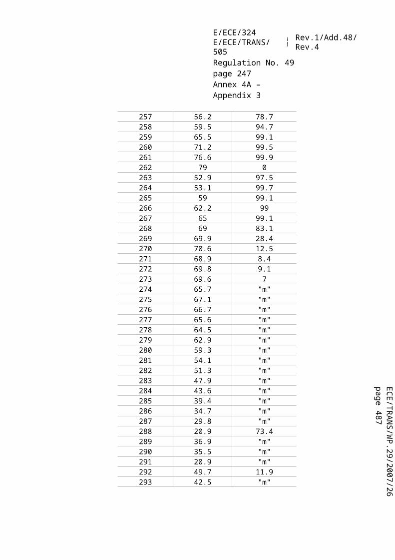
ECE/TR
AN
S/WP.29/2007/26
page 487
E/ECE/324E/ECE/TRANS/505 Rev.1/Add.48/Rev.4
Regulation No. 49page 247Annex 4A – Appendix 7
At high engine loads, the tunnel may be cooled by a non-aggressive means such as a circulating fan, as long as the temperature of the cooling medium is not below 293 K (20 °C).
HE heat exchanger (figures 16 and17)
The heat exchanger shall be of sufficient capacity to maintain the temperature at the inlet to the suction blower SB within ± 11 K of the average operating temperature observed during the test.
2.3. Full flow dilution system
A dilution system is described in figure 20 based upon the dilution of the total exhaust using the CVS (constant volume dampling) concept. The total volume of the mixture of exhaust and dilution air shall be measured. Either a PDP or a CFV system may be used.
For subsequent collection of the particulates, a sample of the dilute exhaust gas is passed to the particulate sampling system (paragraph 2.4., figures 21 and 22). If this is done directly, it is referred to as single dilution. If the sample is diluted once more in the secondary dilution tunnel, it is referred to as double dilution. This is useful, if the filter face temperature requirement cannot be met with single dilution. Although partly a dilution system, the double dilution system is described as a modification of a particulate sampling system in paragraph 2.4., figure 22, since it shares most of the parts with a typical particulate sampling system.

E/ECE/324E/ECE/TRANS/505 Rev.1/Add.48/Rev.4
Regulation No. 49page 248Annex 4A – Appendix 7
Figure 20Full flow dilution system to background filter
DAF HE
PDP
CFV
PTTPSP
EP optional
optional
air
exhaust
to background filter
see figure 21
vent vent
FC3
FC3
if EFC is used
to particulate sampling systemor to DDS see figure 22
The total amount of raw exhaust gas is mixed in the dilution tunnel DT with the dilution air. The diluted exhaust gas flow rate is measured either with a positive displacement pump PDP or with a critical flow venturi CFV. A heat exchanger HE or electronic flow compensation EFC may be used for proportional particulate sampling and for flow determination. Since particulate mass determination is based on the total diluted exhaust gas flow, the dilution ratio is not required to be calculated.
2.3.1. Components of figure 20
EP exhaust pipe
The exhaust pipe length from the exit of the engine exhaust manifold, turbocharger outlet or aftertreatment device to the dilution tunnel shall not exceed 10 m. If the exhaust pipe downstream of the engine exhaust manifold, turbocharger outlet or aftertreatment device exceeds 4 m in length, then all tubing in excess of 4 m shall be insulated, except for an in-line smokemeter, if used. The radial thickness of the insulation shall be at least 25 mm. The thermal conductivity of the insulating material shall have a value no greater than 0.1 W/mK measured at 673 K. To reduce the thermal inertia of the exhaust pipe a thickness to diameter ratio of 0.015 or less is recommended. The use of flexible sections shall be limited to a length to diameter ratio of 12 or less.

ECE/TR
AN
S/WP.29/2007/26
page 487
E/ECE/324E/ECE/TRANS/505 Rev.1/Add.48/Rev.4
Regulation No. 49page 249Annex 4A – Appendix 7
PDP positive displacement pump
The PDP meters total diluted exhaust flow from the number of the pump revolutions and the pump displacement. The exhaust system backpressure shall not be artificially lowered by the PDP or dilution air inlet system. Static exhaust backpressure measured with the PDP system operating shall remain within ± 1.5 kPa of the static pressure measured without connection to the PDP at identical engine speed and load. The gas mixture temperature immediately ahead of the PDP shall be within ± 6 K of the average operating temperature observed during the test, when no flow compensation is used. Flow compensation may only be used if the temperature at the inlet to the PDP does not exceed 323 K (50 °C).
CFV critical flow venturi
CFV measures total diluted exhaust flow by maintaining the flow at choked conditions (critical flow). Static exhaust backpressure measured with the CFV system operating shall remain within ± 1.5 kPa of the static pressure measured without connection to the CFV at identical engine speed and load. The gas mixture temperature immediately ahead of the CFV shall be within ± 11 K of the average operating temperature observed during the test, when no flow compensation is used.
HE heat exchanger (optional, if EFC is used)
The heat exchanger shall be of sufficient capacity to maintain the temperature within the limits required above.
EFC electronic flow compensation (optional, if HE is used)
If the temperature at the inlet to either the PDP or CFV is not kept within the limits stated above, a flow compensation system is required for continuous measurement of the flow rate and control of the proportional sampling in the particulate system. To that purpose, the continuously measured flow rate signals are used to correct the sample flow rate through the particulate filters of the particulate sampling system (see paragraph 2.4., figures 21and 22), accordingly.
DT dilution tunnel
The dilution tunnel:(a) shall be small enough in diameter to cause turbulent flow (Reynolds number
greater than 4,000) and of sufficient length to cause complete mixing of the exhaust and dilution air; a mixing orifice may be used;
(b) shall be at least 460 mm in diameter with a single dilution system;(c) shall be at least 210 mm in diameter with a double dilution system;(d) may be insulated.

E/ECE/324E/ECE/TRANS/505 Rev.1/Add.48/Rev.4
Regulation No. 49page 250Annex 4A – Appendix 7
The engine exhaust shall be directed downstream at the point where it is introduced into the dilution tunnel, and thoroughly mixed.
When using single dilution, a sample from the dilution tunnel is transferred to the particulate sampling system (paragraph 2.4., figure 21). The flow capacity of the PDP or CFV shall be sufficient to maintain the diluted exhaust at a temperature of less than or equal to 325 K (52°C) immediately before the primary particulate filter.
When using double dilution, a sample from the dilution tunnel is transferred to the secondary dilution tunnel where it is further diluted, and then passed through the sampling filters (paragraph 2.4., figure 22). The flow capacity of the PDP or CFV shall be sufficient to maintain the diluted exhaust stream in the DT at a temperature of less than or equal to 464 K (191 °C) at the sampling zone. The secondary dilution system shall provide sufficient secondary dilution air to maintain the doubly-diluted exhaust stream at a temperature of less than or equal to 325 K (52 °C) immediately before the primary particulate filter.
DAF dilution air filter
It is recommended that the dilution air be filtered and charcoal scrubbed to eliminate background hydrocarbons. At the engine manufacturers request the dilution air shall be sampled according to good engineering practice to determine the background particulate levels, which can then be subtracted from the values measured in the diluted exhaust.
PSP particulate sampling probe
The probe is the leading section of PTT and:(a) shall be installed facing upstream at a point where the dilution air and exhaust gas
are well mixed, i.e. on the dilution tunnel (DT) centreline approximately 10 tunnel diameters downstream of the point where the exhaust enters the dilution tunnel;
(b) shall be of 12 mm minimum inside diameter;(c) may be heated to no greater than 325 K (52 °C) wall temperature by direct heating
or by dilution air pre-heating, provided the air temperature does not exceed 325 K (52 °C) prior to the introduction of the exhaust in the dilution tunnel;
(d) may be insulated.
2.4. Particulate sampling system
The particulate sampling system is required for collecting the particulates on the particulate filter. In the case of total sampling partial flow dilution, which consists of passing the entire diluted exhaust sample through the filters, dilution (paragraph 2.2., figures 14 and 18) and sampling system usually form an integral unit. In the case of fractional sampling partial flow dilution or full flow dilution, which consists of passing
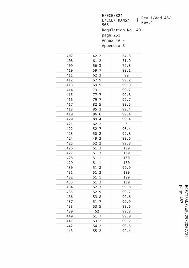
ECE/TR
AN
S/WP.29/2007/26
page 487
E/ECE/324E/ECE/TRANS/505 Rev.1/Add.48/Rev.4
Regulation No. 49page 251Annex 4A – Appendix 7
through the filters only a portion of the diluted exhaust, the dilution (paragraph 2.2., figures 11, 12, 13, 15, 16, 17, 19; paragraph 2.3., figure 20) and sampling systems usually form different units.
In this Regulation, the double dilution system (figure 22) of a full flow dilution system is considered as a specific modification of a typical particulate sampling system as shown in figure 21. The double dilution system includes all important parts of the particulate sampling system, like filter holders and sampling pump, and additionally some dilution features, like a dilution air supply and a secondary dilution tunnel.
In order to avoid any impact on the control loops, it is recommended that the sample pump be running throughout the complete test procedure. For the single filter method, a bypass system shall be used for passing the sample through the sampling filters at the desired times. Interference of the switching procedure on the control loops shall be minimized.
Figure 21Particulate sampling system
FM3
FC3
FH
BV
optional
from EGA
from PDP
from CFV
from GFUEL
or
or
or
PTT
P
from dilution tunnel DTsee figures 11 to 20
A sample of the diluted exhaust gas is taken from the dilution tunnel DT of a partial flow or full flow dilution system through the particulate sampling probe PSP and the particulate transfer tube PTT by means of the sampling pump P. The sample is passed through the filter holder(s) FH that contain the particulate sampling filters. The sample flow rate is controlled by the flow controller FC3. If electronic flow compensation EFC (see figure 20) is used, the diluted exhaust gas flow is used as command signal for FC3.

E/ECE/324E/ECE/TRANS/505 Rev.1/Add.48/Rev.4
Regulation No. 49page 252Annex 4A – Appendix 7
Figure 22Double dilution system (full flow system only)
FM4 DPSDT BV
FH FM3
BV optional
PTT
P
FC3PDPorCFV
from dilutiontunnel DTsee figure 20
vent
A sample of the diluted exhaust gas is transferred from the dilution tunnel DT of a full flow dilution system through the particulate sampling probe PSP and the particulate transfer tube PTT to the secondary dilution tunnel SDT, where it is diluted once more. The sample is then passed through the filter holder(s) FH that contain the particulate sampling filters. The dilution air flow rate is usually constant whereas the sample flow rate is controlled by the flow controller FC3. If electronic flow compensation EFC (see figure 20) is used, the total diluted exhaust gas flow is used as command signal for FC3.
2.4.1. Components of figures 21 and 22
PTT Particulate transfer tube (figures 21 and 22)
The particulate transfer tube shall not exceed 1,020 mm in length, and shall be minimized in length whenever possible. As indicated below (i.e. for partial flow dilution fractional sampling systems and for full flow dilution systems), the length of the sampling probes (SP, ISP, PSP, respectively, see paragraphs 2.2. and 2.3.) shall be included.
The dimensions are valid for:(a) the partial flow dilution fractional sampling type and the full flow single dilution
system from the tip of the probe (SP, ISP, PSP, respectively) to the filter holder;(b) the partial flow dilution total sampling type from the end of the dilution tunnel to
the filter holder;(c) the full flow double dilution system from the tip of the probe (PSP) to the
secondary dilution tunnel.
The transfer tube:(a) may be heated to no greater than 325K (52 °C) wall temperature by direct heating
or by dilution air pre-heating, provided the air temperature does not exceed 325 K (52 °C) prior to the introduction of the exhaust in the dilution tunnel;
(b) may be insulated.

ECE/TR
AN
S/WP.29/2007/26
page 487
E/ECE/324E/ECE/TRANS/505 Rev.1/Add.48/Rev.4
Regulation No. 49page 253Annex 4A – Appendix 7
SDT secondary dilution tunnel (figure 22)The secondary dilution tunnel should have a minimum diameter of 75 mm, and should be of sufficient length so as to provide a residence time of at least 0.25 seconds for the doubly-diluted sample. The primary filter holder FH shall be located within 300 mm of the exit of the SDT.
The secondary dilution tunnel:(a) may be heated to no greater than 325 K (52 °C) wall temperature by direct heating
or by dilution air pre-heating, provided the air temperature does not exceed 325 K (52 °C) prior to the introduction of the exhaust in the dilution tunnel;
(b) may be insulated.
FH Filter holder(s) (figures 21 and 22)
The filter holder shall meet the requirements of paragraph 4.1.3. of Appendix 4 to this annex.
The filter holder:(a) may be heated to no greater than 325 K (52 °C) wall temperature by direct heating
or by dilution air pre-heating, provided the air temperature does not exceed 325 K (52 °C) prior to the introduction of the exhaust in the dilution tunnel;
(b) may be insulated.
P sampling pump (figures 21 and 22)
The particulate sampling pump shall be located sufficiently distant from the tunnel so that the inlet gas temperature is maintained constant (± 3 K), if flow correction by FC3 is not used.
DP dilution air pump (figure 22)
The dilution air pump shall be located so that the secondary dilution air is supplied at a temperature of 298 K ± 5 K (25 °C ± 5 °C), if the dilution air is not preheated.
FC3 Flow controller (figures 21 and 22)
A flow controller shall be used to compensate the particulate sample flow rate for temperature and backpressure variations in the sample path, if no other means are available. The flow controller is required if electronic flow compensation EFC (see figure 20) is used.

E/ECE/324E/ECE/TRANS/505 Rev.1/Add.48/Rev.4
Regulation No. 49page 254Annex 4A – Appendix 7
FM3 Flow measurement device (figures 21 and 22)
The gas meter or flow instrumentation for the particulate sample flow shall be located sufficiently distant from the sampling pump P so that the inlet gas temperature remains constant (± 3 K), if flow correction by FC3 is not used.
FM4 flow measurement device (figure 22)
The gas meter or flow instrumentation for the dilution air flow shall be located so that the inlet gas temperature remains at 298 K ± 5 K (25 °C ± 5 °C).
BV ball valve (optional)
The ball valve shall have an inside diameter not less than the inside diameter of the particulate transfer tube PTT, and a switching time of less than 0.5 seconds.
Note: If the ambient temperature in the vicinity of PSP, PTT, SDT, and FH is below 293 K (20 °C), precautions should be taken to avoid particle losses onto the cool wall of these parts. Therefore, heating and/or insulating these parts within the limits given in the respective descriptions is recommended. It is also recommended that the filter face temperature during sampling be not below 293 K (20 °C).At high engine loads, the above parts may be cooled by a non-aggressive means such as a circulating fan, as long as the temperature of the cooling medium is not below 293 K (20 °C).
3. DETERMINATION OF SMOKE
3.1. Introduction
Paragraphs 3.2. and 3.3. and figures 23 and 24 contain detailed descriptions of the recommended opacimeter systems. Since various configurations can produce equivalent results, exact conformance with figures 23 and 24 is not required. Additional components such as instruments, valves, solenoids, pumps, and switches may be used to provide additional information and coordinate the functions of the component systems. Other components which are not needed to maintain the accuracy on some systems, may be excluded if their exclusion is based upon good engineering judgement.
The principle of measurement is that light is transmitted through a specific length of the smoke to be measured and that proportion of the incident light which reaches a receiver is used to assess the light obscuration properties of the medium. The smoke measurement depends upon the design of the apparatus, and may be done in the exhaust pipe (full flow in-line opacimeter), at the end of the exhaust pipe (full flow end-of-line opacimeter) or by taking a sample from the exhaust pipe (partial flow opacimeter). For

ECE/TR
AN
S/WP.29/2007/26
page 487
E/ECE/324E/ECE/TRANS/505 Rev.1/Add.48/Rev.4
Regulation No. 49page 255Annex 4A – Appendix 7
the determination of the light absorption coefficient from the opacity signal, the optical path length of the instrument shall be supplied by the instrument manufacturer.
3.2. Full flow opacimeter
Two general types of full flow opacimeters may be used (figure 23). With the in-line opacimeter, the opacity of the full exhaust plume within the exhaust pipe is measured. With this type of opacimeter, the effective optical path length is a function of the opacimeter design.
With the end-of-line opacimeter, the opacity of the full exhaust plume is measured as it exits the exhaust pipe. With this type of opacimeter, the effective optical path length is a function of the exhaust pipe design and the distance between the end of the exhaust pipe and the opacimeter.
Figure 23Full flow opacimeter
EP
OPL
T1 (optional)
CL
LDLS
CL
3.2.1. Components of figure 23
EP exhaust pipe
With an in-line opacimeter, there shall be no change in the exhaust pipe diameter within 3 exhaust pipe diameters before or after the measuring zone. If the diameter of the measuring zone is greater than the diameter of the exhaust pipe, a pipe gradually convergent before the measuring zone is recommended.
With an end-of-line opacimeter, the terminal 0.6 m of the exhaust pipe shall be of circular cross section and be free from elbows and bends. The end of the exhaust pipe

E/ECE/324E/ECE/TRANS/505 Rev.1/Add.48/Rev.4
Regulation No. 49page 256Annex 4A – Appendix 7
shall be cut off squarely. The opacimeter shall be mounted centrally to the plume within 25 ± 5 mm of the end of the exhaust pipe.
OPL optical path length
The length of the smoke obscured optical path between the opacimeter light source and the receiver, corrected as necessary for non-uniformity due to density gradients and fringe effect. The optical path length shall be submitted by the instrument manufacturer taking into account any measures against sooting (e.g. purge air). If the optical path length is not available, it shall be determined in accordance with ISO 11614, paragraph 11.6.5. For the correct determination of the optical path length, a minimum exhaust gas velocity of 20 m/s is required.
LS light source
The light source shall be an incandescent lamp with a colour temperature in the range of 2,800 to 3,250 K or a green light emitting diode (LED) with a spectral peak between 550 and 570 nm. The light source shall be protected against sooting by means that do not influence the optical path length beyond the manufacturers specifications.
LD light detector
The detector shall be a photocell or a photodiode (with a filter, if necessary). In the case of an incandescent light source, the receiver shall have a peak spectral response similar to the phototopic curve of the human eye (maximum response) in the range of 550 to 570 nm, to less than 4 per cent of that maximum response below 430 nm and above 680 nm. The light detector shall be protected against sooting by means that do not influence the optical path length beyond the manufacturers specifications.
CL collimating lens
The light output shall be collimated to a beam with a maximum diameter of 30 mm. The rays of the light beam shall be parallel within a tolerance of 3° of the optical axis.
T1 temperature sensor (optional)
The exhaust gas temperature may be monitored over the test.
3.3. Partial flow opacimeter
With the partial flow opacimeter (figure 24), a representative exhaust sample is taken from the exhaust pipe and passed through a transfer line to the measuring chamber. With this type of opacimeter, the effective optical path length is a function of the

ECE/TR
AN
S/WP.29/2007/26
page 487
E/ECE/324E/ECE/TRANS/505 Rev.1/Add.48/Rev.4
Regulation No. 49page 257Annex 4A – Appendix 7
opacimeter design. The response times referred to in the following paragraph apply to the minimum flow rate of the opacimeter, as specified by the instrument manufacturer.
Figure 24Partial flow opacimeter
Exhaust
EP
SP
TT
T1FM
P (optional)
OPL
MC
CL
LS
CL
LD
3.3.1. Components of figure 24
EP exhaust pipe
The exhaust pipe shall be a straight pipe of at least 6-pipe diameters upstream and 3-pipe diameters downstream of the tip of the probe.
SP sampling probe
The sampling probe shall be an open tube facing upstream on or about the exhaust pipe centreline. The clearance with the wall of the tailpipe shall be at least 5 mm. The probe diameter shall ensure a representative sampling and a sufficient flow through the opacimeter.
TT transfer tube
The transfer tube shall:(a) Be as short as possible and ensure an exhaust gas temperature of 373 ± 30 K
(100 °C ± 30 °C) at the entrance to the measuring chamber.

E/ECE/324E/ECE/TRANS/505 Rev.1/Add.48/Rev.4
Regulation No. 49page 258Annex 4A – Appendix 7
(b) Have a wall temperature sufficiently above the dew point of the exhaust gas to prevent condensation.
(c) Be equal to the diameter of the sampling probe over the entire length.(d) Have a response time of less than 0.05 s at minimum instrument flow, as
determined according to paragraph 5.2.4. of Appendix 4 to this annex.(e) Have no significant effect on the smoke peak.
FM flow measurement device
Flow instrumentation to detect the correct flow into the measuring chamber. The minimum and maximum flow rates shall be specified by the instrument manufacturer, and shall be such that the response time requirement of TT and the optical path length specifications are met. The flow measurement device may be close to the sampling pump, P, if used.
MC measuring chamber
The measuring chamber shall have a non-reflective internal surface, or equivalent optical environment. The impingement of stray light on the detector due to internal reflections of diffusion effects shall be reduced to a minimum.
The pressure of the gas in the measuring chamber shall not differ from the atmospheric pressure by more than 0.75 kPa. Where this is not possible by design, the opacimeter reading shall be converted to atmospheric pressure.
The wall temperature of the measuring chamber shall be set to within ± 5 K between 343 K (70 °C) and 373 K (100 °C), but in any case sufficiently above the dew point of the exhaust gas to prevent condensation. The measuring chamber shall be equipped with appropriate devices for measuring the temperature.
OPL optical path length
The length of the smoke obscured optical path between the opacimeter light source and the receiver, corrected as necessary for non-uniformity due to density gradients and fringe effect. The optical path length shall be submitted by the instrument manufacturer taking into account any measures against sooting (e.g. purge air). If the optical path length is not available, it shall be determined in accordance with ISO 11614, paragraph 11.6.5.
LS light source
The light source shall be an incandescent lamp with a colour temperature in the range of 2,800 to 3,250 K or a green light emitting diode (LED) with a spectral peak

ECE/TR
AN
S/WP.29/2007/26
page 487
E/ECE/324E/ECE/TRANS/505 Rev.1/Add.48/Rev.4
Regulation No. 49page 259Annex 4A – Appendix 7
between 550 and 570 nm. The light source shall be protected against sooting by means that do not influence the optical path length beyond the manufacturer's specifications.
LD light detector
The detector shall be a photocell or a photodiode (with a filter, if necessary). In the case of an incandescent light source, the receiver shall have a peak spectral response similar to the phototopic curve of the human eye (maximum response) in the range of 550 to 570 nm, to less than 4 per cent of that maximum response below 430 nm and above 680 nm. The light detector shall be protected against sooting by means that do not influence the optical path length beyond the manufacturer's specifications.
CL collimating lens
The light output shall be collimated to a beam with a maximum diameter of 30 mm. The rays of the light beam shall be parallel within a tolerance of 3° of the optical axis.
T1 temperature sensor
To monitor the exhaust gas temperature at the entrance to the measuring chamber.
P sampling pump (optional)
A sampling pump downstream of the measuring chamber may be used to transfer the sample gas through the measuring chamber.

E/ECE/324E/ECE/TRANS/505 Rev.1/Add.48/Rev.4
Regulation No. 49page 260Annex 4B
Annex 4B
TEST PROCEDURE FOR COMPRESSION-IGNITION (C.I.) ENGINES AND POSITIVE-IGNITION (P.I.) ENGINES FUELLED WITH NATURAL GAS (NG) OR LIQUEFIED PETROLEUM GAS (LPG) INCORPORATING THE WORLD-WIDE HARMONIZED
HEAVY-DUTY CERTIFICATION (WHDC, global technical regulation (gtr) No. 4)
1. APPLICABILITY
This annex is not applicable for the purpose of type approval according to this Regulation for the time being. It will be made applicable in the future.
2. Reserved 21/.
3. DEFINITIONS, SYMBOLS AND ABBREVIATIONS
3.1. Definitions
For the purpose of this Regulation,
3.1.1. "continuous regeneration" means the regeneration process of an exhaust after-treatment system that occurs either permanently or at least once per WHTC hot start test. Such a regeneration process will not require a special test procedure.
3.1.2. "delay time" means the difference in time between the change of the component to be measured at the reference point and a system response of 10 per cent of the final reading (t10) with the sampling probe being defined as the reference point. For the gaseous components, this is the transport time of the measured component from the sampling probe to the detector with the sampling probe being defined as the reference point.
3.1.3. "deNOx system" means an exhaust after-treatment system designed to reduce emissions of oxides of nitrogen (NOx) (e.g. passive and active lean NOx catalysts, NOx adsorbers and selective catalytic reduction (SCR) systems).
3.1.4. "diesel engine" means an engine which works on the compression-ignition principle.
3.1.5. "engine family" means a manufacturers grouping of engines which, through their design as defined in paragraph 5.2. of this annex, have similar exhaust emission characteristics; all members of the family must comply with the applicable emission limit values.
21/ The numbering of this annex is consistent with the numbering of the WHDC gtr. However, some sections of the WHDC gtr are not needed in this annex.

ECE/TR
AN
S/WP.29/2007/26
page 487
E/ECE/324E/ECE/TRANS/505 Rev.1/Add.48/Rev.4
Regulation No. 49page 261Annex 4B
3.1.6. "engine system" means the engine, the emission control system and the communication interface (hardware and messages) between the engine system electronic control unit(s) (ECU) and any other powertrain or vehicle control unit.
3.1.7. "engine type" means a category of engines which do not differ in essential engine characteristics.
3.1.8. "exhaust after-treatment system" means a catalyst (oxidation or 3-way), particulate filter, deNOx system, combined deNOx particulate filter or any other emission-reducing device that is installed downstream of the engine. This definition excludes exhaust gas recirculation (EGR), which is considered an integral part of the engine.
3.1.9. "full flow dilution method" means the process of mixing the total exhaust flow with dilution air prior to separating a fraction of the diluted exhaust stream for analysis.
3.1.10. "gas engine" means an engine which is fuelled with natural gas (NG) or liquefied petroleum gas (LPG).
3.1.11. "gaseous pollutants" means carbon monoxide, hydrocarbons and/or non-methane hydrocarbons (assuming a ratio of CH1.85 for diesel, CH2.525 for LPG and CH2.93 for NG, and an assumed molecule CH3O0.5 for ethanol fuelled diesel engines), methane (assuming a ratio of CH4 for NG) and oxides of nitrogen (expressed in nitrogen dioxide (NO2) equivalent).
3.1.12. "high speed ( n hi)" means the highest engine speed where 70 per cent of the declared maximum power occurs.
3.1.13. "low speed ( n lo)" means the lowest engine speed where 55 per cent of the declared maximum power occurs.
3.1.14. "maximum power (Pmax)" means the maximum power in kW as specified by the manufacturer.
3.1.15. "maximum torque speed" means the engine speed at which the maximum torque is obtained from the engine, as specified by the manufacturer.
3.1.16. "parent engine" means an engine selected from an engine family in such a way that its emissions characteristics are representative for that engine family.
3.1.17. "particulate after-treatment device" means an exhaust after-treatment system designed to reduce emissions of particulate pollutants (PM) through a mechanical, aerodynamic, diffusional or inertial separation.

E/ECE/324E/ECE/TRANS/505 Rev.1/Add.48/Rev.4
Regulation No. 49page 262Annex 4B
3.1.18. "partial flow dilution method" means the process of separating a part from the total exhaust flow, then mixing it with an appropriate amount of dilution air prior to the particulate sampling filter.
3.1.19. "particulate matter (PM)" means any material collected on a specified filter medium after diluting exhaust with clean filtered air to a temperature between 315 K (42 °C) and 325 K (52 °C), as measured at a point immediately upstream of the filter; this is primarily carbon, condensed hydrocarbons, and sulphates with associated water.
3.1.20. "per cent load" means the fraction of the maximum available torque at an engine speed.
3.1.21. "periodic regeneration" means the regeneration process of an exhaust after-treatment system that occurs periodically in typically less than 100 hours of normal engine operation. During cycles where regeneration occurs, emission standards may be exceeded.
3.1.22. "ramped steady state test cycle" means a test cycle with a sequence of steady state engine test modes with defined speed and torque criteria at each mode and defined ramps between these modes (WHSC).
3.1.23. "rated speed" means the maximum full load speed allowed by the governor as specified by the manufacturer in his sales and service literature, or, if such a governor is not present, the speed at which the maximum power is obtained from the engine, as specified by the manufacturer in his sales and service literature.
3.1.24. "response time" means the difference in time between the change of the component to be measured at the reference point and a system response of 90 per cent of the final reading (t90) with the sampling probe being defined as the reference point, whereby the change of the measured component is at least 60 per cent full scale (FS) and takes place in less than 0.1 second. The system response time consists of the delay time to the system and of the rise time of the system.
3.1.25. "rise time" means the difference in time between the 10 per cent and 90 per cent response of the final reading (t90 – t10).
3.1.26. "specific emissions" means the mass emissions expressed in g/kWh.
3.1.27. "test cycle" means a sequence of test points each with a defined speed and torque to be followed by the engine under steady state (WHSC test) or transient operating conditions (WHTC).
3.1.28. "transformation time" means the difference in time between the change of the component to be measured at the reference point and a system response of 50 per

ECE/TR
AN
S/WP.29/2007/26
page 487
E/ECE/324E/ECE/TRANS/505 Rev.1/Add.48/Rev.4
Regulation No. 49page 263Annex 4B
cent of the final reading (t50) with the sampling probe being defined as the reference point. The transformation time is used for the signal alignment of different measurement instruments.
3.1.29. "transient test cycle" means a test cycle with a sequence of normalized speed and torque values that vary relatively quickly with time (WHTC).
3.1.30. "useful life" means the relevant period of distance and/or time over which compliance with the relevant gaseous and particulate emission limits has to be assured.
Time
Res
pons
e
t10
t50
t90
step inputresponse time
transformation time
delay time rise time
Figure 1: Definitions of system response
3.2. General symbols
Symbol Unit TermA/Fst - Stoichiometric air to fuel ratio
c ppm/Vol per cent Concentrationcd ppm/Vol per cent Concentration on dry basiscw ppm/Vol per cent Concentration on wet basiscb ppm/Vol per cent Background concentrationCd - Discharge coefficient of SSVd m DiameterdV m Throat diameter of venturiD0 m3/s PDP calibration interceptD - Dilution factort s Time intervalegas g/kWh Specific emission of gaseous componentsePM g/kWh Specific emission of particulates

E/ECE/324E/ECE/TRANS/505 Rev.1/Add.48/Rev.4
Regulation No. 49page 264Annex 4B
Symbol Unit Termep g/kWh Specific emission during regenerationew g/kWh Weighted specific emission
ECO2 per cent CO2 quench of NOx analyzerEE per cent Ethane efficiency
EH2O per cent Water quench of NOx analyzerEM per cent Methane efficiency
ENOx per cent Efficiency of NOx converterf Hz Data sampling ratefa - Laboratory atmospheric factorFs - Stoichiometric factorHa g/kg Absolute humidity of the intake airHd g/kg Absolute humidity of the dilution airi - Subscript denoting an instantaneous measurement (e.g. 1 Hz)kf - Fuel specific factor
kh,D - Humidity correction factor for NOx for CI engines kh,G - Humidity correction factor for NOx for PI engines kr - Regeneration factor
kw,a - Dry to wet correction factor for the intake airkw,d - Dry to wet correction factor for the dilution airkw,e - Dry to wet correction factor for the diluted exhaust gaskw,r - Dry to wet correction factor for the raw exhaust gasKV - CFV calibration function - Excess air ratiomd kg Mass of the dilution air sample passed through the particulate
sampling filtersmed kg Total diluted exhaust mass over the cyclemedf kg Mass of equivalent diluted exhaust gas over the test cyclemew kg Total exhaust mass over the cyclemf mg Particulate sample mass collectedmf,d mg Particulate sample mass of the dilution air collectedmgas g Mass of gaseous emissions over the test cyclemPM g Mass of particulate emissions over the test cyclemse kg Exhaust sample mass over the test cycle msed kg Mass of diluted exhaust gas passing the dilution tunnelmsep kg Mass of diluted exhaust gas passing the particulate collection
filtersmssd kg Mass of secondary dilution airMa g/mol Molar mass of the intake airMe g/mol Molar mass of the exhaust
Mgas g/mol Molar mass of gaseous components

ECE/TR
AN
S/WP.29/2007/26
page 487
E/ECE/324E/ECE/TRANS/505 Rev.1/Add.48/Rev.4
Regulation No. 49page 265Annex 4B
Symbol Unit Termn - Number of measurementsnr - Number of measurements during regenerationn min-1 Engine rotational speednhi min-1 High engine speednlo min-1 Low engine speednpref min-1 Preferred engine speednp r/s PDP pump speedpa kPa Saturation vapour pressure of engine intake airpb kPa Total atmospheric pressurepd kPa Saturation vapour pressure of the dilution airpp kPa Absolute pressurepr kPa Water vapour pressure after cooling bathps kPa Dry atmospheric pressure
qmad
kg/s Intake air mass flow rate on dry basisq
mawkg/s Intake air mass flow rate on wet basis
qmCe
kg/s Carbon mass flow rate in the raw exhaust gasq
mCfkg/s Carbon mass flow rate into the engine
qmCp
kg/s Carbon mass flow rate in the partial flow dilution systemq
mdewkg/s Diluted exhaust gas mass flow rate on wet basis
qmdw
kg/s Dilution air mass flow rate on wet basisq
medfkg/s Equivalent diluted exhaust gas mass flow rate on wet basis
qmew
kg/s Exhaust gas mass flow rate on wet basisq
mexkg/s Sample mass flow rate extracted from dilution tunnel
qmf
kg/s Fuel mass flow rateq
mpkg/s Sample flow of exhaust gas into partial flow dilution system
qvCVS m³/s CVS volume rateqvs dm³/min System flow rate of exhaust analyzer systemqvt cm³/min Tracer gas flow raterd - Dilution ratiorD - Diameter ratio of SSVrh - Hydrocarbon response factor of the FIDrm - Methanol response factor of the FIDrp - Pressure ratio of SSVrs - Average sample ratio kg/m³ Densitye kg/m³ Exhaust gas density Standard deviationT K Absolute temperature

E/ECE/324E/ECE/TRANS/505 Rev.1/Add.48/Rev.4
Regulation No. 49page 266Annex 4B
Symbol Unit TermTa K Absolute temperature of the intake airt s Time
t10 s Time between step input and 10 per cent of final readingt50 s Time between step input and 50 per cent of final readingt90 s Time between step input and 90 per cent of final readingu - Ratio between densities of gas component and exhaust gasV0 m3/r PDP gas volume pumped per revolutionVs dm³ System volume of exhaust analyzer bench
Wact kWh Actual cycle work of the test cycleWref kWh Reference cycle work of the test cycleX0 m3/r PDP calibration function
3.3. Symbols and abbreviations for the fuel composition
wALF hydrogen content of fuel, per cent masswBET carbon content of fuel, per cent masswGAM sulphur content of fuel, per cent masswDEL nitrogen content of fuel, per cent masswEPS oxygen content of fuel, per cent mass molar hydrogen ratio (H/C) molar sulphur ratio (S/C) molar nitrogen ratio (N/C) molar oxygen ratio (O/C)referring to a fuel CHONS
3.4. Symbols and abbreviations for the chemical components
C1 Carbon 1 equivalent hydrocarbonCH4 MethaneC2H6 EthaneC3H8 PropaneCO Carbon monoxideCO2 Carbon dioxideDOP Di-octylphtalateHC HydrocarbonsH2O WaterNMHC Non-methane hydrocarbonsNOx Oxides of nitrogenNO Nitric oxideNO2 Nitrogen dioxidePM Particulate matter

ECE/TR
AN
S/WP.29/2007/26
page 487
E/ECE/324E/ECE/TRANS/505 Rev.1/Add.48/Rev.4
Regulation No. 49page 267Annex 4B
3.5. Abbreviations
CFV Critical Flow VenturiCLD Chemiluminescent DetectorCVS Constant Volume SamplingdeNOx NOx after-treatment systemEGR Exhaust gas recirculationFID Flame Ionization DetectorGC Gas ChromatographHCLD Heated Chemiluminescent DetectorHFID Heated Flame Ionization DetectorLPG Liquefied Petroleum GasNDIR Non-Dispersive Infrared (Analyzer) NG Natural GasNMC Non-Methane CutterPDP Positive Displacement PumpPer cent FS Per cent of full scalePFS Partial Flow SystemSSV Subsonic Venturi VGT Variable Geometry Turbine
4. GENERAL REQUIREMENTS
The engine system shall be so designed, constructed and assembled as to enable the engine in normal use to comply with the provisions of this annex during its useful life, as defined in this Regulation.
5. PERFORMANCE REQUIREMENTS
5.1. Emission of gaseous and particulate pollutants
The emissions of gaseous and particulate pollutants by the engine shall be determined on the WHTC and WHSC test cycles, as described in paragraph 7. The measurement systems shall meet the linearity requirements in paragraph 9.2. and the specifications in paragraph 9.3. (gaseous emissions measurement), paragraph 9.4. (particulate measurement) and in Appendix 3 to this annex.
Other systems or analyzers may be approved by the type Approval Authority, if it is found that they yield equivalent results in accordance with paragraph 5.1.1.

E/ECE/324E/ECE/TRANS/505 Rev.1/Add.48/Rev.4
Regulation No. 49page 268Annex 4B
5.1.1. Equivalency
The determination of system equivalency shall be based on a seven-sample pair (or larger) correlation study between the system under consideration and one of the systems of this annex.
"Results" refer to the specific cycle weighted emissions value. The correlation testing is to be performed at the same laboratory, test cell, and on the same engine, and is preferred to be run concurrently. The equivalency of the sample pair averages shall be determined by F-test and t-test statistics as described in Appendix 4 obtained under the laboratory test cell and the engine conditions described above. Outliers shall be determined in accordance with ISO 5725 and excluded from the database. The systems to be used for correlation testing shall be subject to the approval by the type Approval Authority.
5.2. Engine family
5.2.1. General
An engine family is characterized by design parameters. These shall be common to all engines within the family. The engine manufacturer may decide, which engines belong to an engine family, as long as the membership criteria listed in paragraph 5.2.3. are respected. The engine family shall be approved by the type Approval Authority. The manufacturer shall provide to the type Approval Authority the appropriate information relating to the emission levels of the members of the engine family.
5.2.2. Special cases
In some cases there may be interaction between parameters. This shall be taken into consideration to ensure that only engines with similar exhaust emission characteristics are included within the same engine family. These cases shall be identified by the manufacturer and notified to the type Approval Authority. It shall then be taken into account as a criterion for creating a new engine family.
In case of devices or features, which are not listed in paragraph 5.2.3. and which have a strong influence on the level of emissions, this equipment shall be identified by the manufacturer on the basis of good engineering practice, and shall be notified to the type Approval Authority. It shall then be taken into account as a criterion for creating a new engine family.
In addition to the parameters listed in paragraph 5.2.3., the manufacturer may introduce additional criteria allowing the definition of families of more restricted

ECE/TR
AN
S/WP.29/2007/26
page 487
E/ECE/324E/ECE/TRANS/505 Rev.1/Add.48/Rev.4
Regulation No. 49page 269Annex 4B
size. These parameters are not necessarily parameters that have an influence on the level of emissions.
5.2.3. Parameters defining the engine family
5.2.3.1. Combustion cycle(a) 2-stroke cycle(b) 4-stroke cycle(c) Rotary engine(d) Others
5.2.3.2. Configuration of the cylinders
5.2.3.2.1. Position of the cylinders in the block(a) V(b) In line(c) Radial(d) Others (F, W, etc.)
5.2.3.2.2. Relative position of the cylinders
Engines with the same block may belong to the same family as long as their bore center-to-center dimensions are the same.
5.2.3.3. Main cooling medium(a) air(b) water(c) oil
5.2.3.4. Individual cylinder displacement
5.2.3.4.1. Engine with a unit cylinder displacement ≥ 0.75 dm³
In order for engines with a unit cylinder displacement of ≥ 0.75 dm³ to be considered to belong to the same engine family, the spread of their individual cylinder displacements shall not exceed 15 per cent of the largest individual cylinder displacement within the family.
5.2.3.4.2. Engine with a unit cylinder displacement < 0.75 dm³
In order for engines with a unit cylinder displacement of < 0.75 dm³ to be considered to belong to the same engine family, the spread of their individual cylinder displacements shall not exceed 30 per cent of the largest individual cylinder displacement within the family.

E/ECE/324E/ECE/TRANS/505 Rev.1/Add.48/Rev.4
Regulation No. 49page 270Annex 4B
5.2.3.4.3. Engine with other unit cylinder displacement limits
Engines with an individual cylinder displacement that exceeds the limits defined in paragraphs 5.2.3.4.1. and 5.2.3.4.2. may be considered to belong to the same family with the approval of the type Approval Authority. The approval shall be based on technical elements (calculations, simulations, experimental results etc.) showing that exceeding the limits does not have a significant influence on the exhaust emissions.
5.2.3.5. Method of air aspiration(a) naturally aspirated(b) pressure charged(c) pressure charged with charge cooler
5.2.3.6. Fuel type(a) Diesel(b) Natural gas (NG)(c) Liquefied petroleum gas (LPG)(d) Ethanol
5.2.3.7. Combustion chamber type(a) Open chamber(b) Divided chamber(c) Other types
5.2.3.8. Ignition Type(a) Positive ignition(b) Compression ignition
5.2.3.9. Valves and porting(a) Configuration(b) Number of valves per cylinder
5.2.3.10. Fuel supply type(a) Liquid fuel supply type
(i) Pump and (high pressure) line and injector(ii) In-line or distributor pump(iii) Unit pump or unit injector(iv) Common rail(v) Carburettor(s)(vi) Others
(b) Gas fuel supply type(i) Gaseous(ii) Liquid

ECE/TR
AN
S/WP.29/2007/26
page 487
E/ECE/324E/ECE/TRANS/505 Rev.1/Add.48/Rev.4
Regulation No. 49page 271Annex 4B
(iii) Mixing units(iv) Others
(c) Other types
5.2.3.11. Miscellaneous devices(a) Exhaust gas recirculation (EGR)(b) Water injection(c) Air injection(d) Others
5.2.3.12. Electronic control strategy
The presence or absence of an electronic control unit (ECU) on the engine is regarded as a basic parameter of the family.
In the case of electronically controlled engines, the manufacturer shall present the technical elements explaining the grouping of these engines in the same family, i.e. the reasons why these engines can be expected to satisfy the same emission requirements. These elements can be calculations, simulations, estimations, description of injection parameters, experimental results, etc.
Examples of controlled features are:(a) Timing(b) Injection pressure(c) Multiple injections(d) Boost pressure(e) VGT(f) EGR
5.2.3.13. Exhaust after-treatment systems
The function and combination of the following devices are regarded as membership criteria for an engine family:(a) Oxidation catalyst(b) Three-way catalyst(c) DeNOx system with selective reduction of NOx (addition of reducing agent)(d) Other DeNOx systems(e) Particulate trap with passive regeneration(f) Particulate trap with active regeneration (g) Other particulate traps(h) Other devices
When an engine has been certified without after-treatment system, whether as parent engine or as member of the family, then this engine, when equipped with an

E/ECE/324E/ECE/TRANS/505 Rev.1/Add.48/Rev.4
Regulation No. 49page 272Annex 4B
oxidation catalyst, may be included in the same engine family, if it does not require different fuel characteristics.
If it requires specific fuel characteristics (e.g. particulate traps requiring special additives in the fuel to ensure the regeneration process), the decision to include it in the same family shall be based on technical elements provided by the manufacturer. These elements shall indicate that the expected emission level of the equipped engine complies with the same limit value as the non-equipped engine.
When an engine has been certified with after-treatment system, whether as parent engine or as member of a family, whose parent engine is equipped with the same after-treatment system, then this engine, when equipped without after-treatment system, must not be added to the same engine family.
5.2.4. Choice of the parent engine
5.2.4.1. Compression ignition engines
Once the engine family has been agreed by the type Approval Authority, the parent engine of the family shall be selected using the primary criterion of the highest fuel delivery per stroke at the declared maximum torque speed. In the event that two or more engines share this primary criterion, the parent engine shall be selected using the secondary criterion of highest fuel delivery per stroke at rated speed.
5.2.4.2. Positive ignition engines
Once the engine family has been agreed by the type Approval Authority, the parent engine of the family shall be selected using the primary criterion of the largest displacement. In the event that two or more engines share this primary criterion, the parent engine shall be selected using the secondary criterion in the following order of priority:(a) the highest fuel delivery per stroke at the speed of declared rated power;(b) the most advanced spark timing;(c) the lowest EGR rate.
5.2.4.3. Remarks on the choice of the parent engine
The type approval or certification authority may conclude that the worst-case emission of the family can best be characterized by testing additional engines. In this case, the engine manufacturer shall submit the appropriate information to determine the engines within the family likely to have the highest emissions level.

ECE/TR
AN
S/WP.29/2007/26
page 487
E/ECE/324E/ECE/TRANS/505 Rev.1/Add.48/Rev.4
Regulation No. 49page 273Annex 4B
If engines within the family incorporate other features which may be considered to affect exhaust emissions, these features shall also be identified and taken into account in the selection of the parent engine.
If engines within the family meet the same emission values over different useful life periods, this shall be taken into account in the selection of the parent engine.
6. TEST CONDITIONS
6.1. Laboratory test conditions
The absolute temperature (Ta) of the intake air at the inlet to the engine expressed in Kelvin, and the dry atmospheric pressure (ps), expressed in kPa shall be measured and the parameter fa shall be determined according to the following provisions. In multi-cylinder engines having distinct groups of intake manifolds, such as in a "Vee" engine configuration, the average temperature of the distinct groups shall be taken. The parameter fa shall be reported with the test results. For better repeatability and reproducibility of the test results, it is recommended that the parameter fa be such that: 0.93 fa 1.07.(a) Compression-ignition engines:
Naturally aspirated and mechanically supercharged engines:
(1)
Turbocharged engines with or without cooling of the intake air:
(2)
(b) Positive ignition engines:
(3)
6.2. Engines with charge air-cooling
The charge air temperature shall be recorded and shall be, at the rated speed and full load, within 5 K of the maximum charge air temperature specified by the manufacturer. The temperature of the cooling medium shall be at least 293 K (20 °C).

E/ECE/324E/ECE/TRANS/505 Rev.1/Add.48/Rev.4
Regulation No. 49page 274Annex 4B
If a test laboratory system or external blower is used, the charge air temperature shall be set to within 5 K of the maximum charge air temperature specified by the manufacturer at the rated speed and full load. Coolant temperature and coolant flow rate of the charge air cooler at the above set point shall not be changed for the whole test cycle, unless this results in unrepresentative overcooling of the charge air. The charge air cooler volume shall be based upon good engineering practice and shall be representative of the production engine's in-use installation.
6.3. Engine power
The basis of specific emissions measurement is uncorrected power as defined in ECE Regulation No. 85.
Certain auxiliaries, which are only necessary only for the operation of the vehicle and which may be mounted on the engine should be removed for the test. The following incomplete list is given as an example:(a) air compressor for brakes(b) power steering compressor(c) air conditioning compressor(d) pumps for hydraulic actuators
Where auxiliaries have not been removed, the power absorbed by them shall be determined in order to adjust the set values and to calculate the work produced by the engine over the test cycle.
6.4. Engine air intake system
An engine air intake system or a test laboratory system shall be used presenting an air intake restriction within 300 Pa of the maximum value specified by the manufacturer for a clean air cleaner at the rated speed and full load.
6.5. Engine exhaust system
An engine exhaust system or a test laboratory system shall be used presenting an exhaust backpressure within 650 Pa of the maximum value specified by the manufacturer at the rated speed and full load. The exhaust system shall conform to the requirements for exhaust gas sampling, as set out in paragraphs 8.3.2.2. and 8.3.3.2.
6.6. Engine with exhaust after-treatment system
If the engine is equipped with an exhaust after-treatment system, the exhaust pipe shall have the same diameter as found in-use for at least four pipe diameters upstream to the inlet of the beginning of the expansion section containing the after-

ECE/TR
AN
S/WP.29/2007/26
page 487
E/ECE/324E/ECE/TRANS/505 Rev.1/Add.48/Rev.4
Regulation No. 49page 275Annex 4B
treatment device. The distance from the exhaust manifold flange or turbocharger outlet to the exhaust after-treatment device shall be the same as in the vehicle configuration or within the distance specifications of the manufacturer. The exhaust backpressure or restriction shall follow the same criteria as above, and may be set with a valve. The after-treatment container may be removed during dummy tests and during engine mapping, and replaced with an equivalent container having an inactive catalyst support.
The emissions measured on the test cycle shall be representative of the emissions in the field. In the case of an engine equipped with a exhaust after-treatment system that requires the consumption of a reagent, the reagent used for all tests shall be declared by the manufacturer.
For engines equipped with exhaust after-treatment systems that are regenerated on a periodic basis, as described in paragraph 6.6.2., emission results shall be adjusted to account for regeneration events In this case, the average emission depends on the frequency of the regeneration event in terms of fraction of tests during which the regeneration occurs.
After-treatment systems with continuous regeneration according to paragraph 6.6.1. do not require a special test procedure.
6.6.1. Continuous regeneration
For an exhaust after-treatment system based on a continuous regeneration process the emissions shall be measured on an after-treatment system that has been stabilized so as to result in repeatable emissions behaviour.
The regeneration process shall occur at least once during the WHTC test and the manufacturer shall declare the normal conditions under which regeneration occurs (soot load, temperature, exhaust back-pressure, etc.).
In order to demonstrate that the regeneration process is continuous, at least three WHTC hot start tests shall be conducted. During the tests, exhaust temperatures and pressures shall be recorded (temperature before and after the after-treatment system, exhaust back pressure, etc.).
The after-treatment system is considered to be satisfactory if the conditions declared by the manufacturer occur during the test during a sufficient time and the emission results do not scatter by more than ±15 per cent.
If the exhaust after-treatment system has a security mode that shifts to a periodic regeneration mode, it shall be checked according to paragraph 6.6.2. For that

E/ECE/324E/ECE/TRANS/505 Rev.1/Add.48/Rev.4
Regulation No. 49page 276Annex 4B
specific case, the applicable emission limits may be exceeded and would not be weighted.
6.6.2. Periodic regeneration
For an exhaust after-treatment based on a periodic regeneration process, the emissions shall be measured on at least three WHTC tests, one during and two outside a regeneration event on a stabilized after-treatment system, and the results be weighted.
The regeneration process shall occur at least once during the WHTC test. The engine may be equipped with a switch capable of preventing or permitting the regeneration process provided this operation has no effect on the original engine calibration.
The manufacturer shall declare the normal parameter conditions under which the regeneration process occurs (soot load, temperature, exhaust back-pressure, etc.) and its duration based on the number of cycles (nr ). The manufacturer shall also provide all the data to determine the number of cycles between two regenerations (n). The exact procedure to determine this time shall be agreed by the type Approval Authority based upon good engineering judgement.
The manufacturer shall provide an after-treatment system that has been loaded in order to achieve regeneration during a WHTC test. Regeneration shall not occur during this engine-conditioning phase.
Average emissions between regeneration phases shall be determined from the arithmetic mean of several approximately equidistant WHTC hot start tests. As a minimum, at least one WHTC as close as possible prior to a regeneration test and one WHTC immediately after a regeneration test shall be conducted. As an alternative, the manufacturer may provide data to show that the emissions remain constant ( 15 per cent) between regeneration phases. In this case, the emissions of only one WHTC test may be used.
During the regeneration test, all the data needed to detect regeneration shall be recorded (CO or NOx emissions, temperature before and after the after-treatment system, exhaust back pressure, etc.).
During the regeneration process, the applicable emission limits may be exceeded.
The measured emissions shall be weighted according to paragraph 8.5.2.2., and the final weighted result shall not exceed the applicable emission limits. The test procedure is schematically shown in figure 2.

ECE/TR
AN
S/WP.29/2007/26
page 487
E/ECE/324E/ECE/TRANS/505 Rev.1/Add.48/Rev.4
Regulation No. 49page 277Annex 4B
0
0,2
0,4
0,6
0,8
1
1,2
1,4
1,6
0 0,5 1 1,5 2 2,5 3 3,5 4 4,5
Number of cycles
Em
issi
ons [
g/kW
h]
n nr
Mean emissions during sampling e1...n
e1, 2, 3, ….n
Emissions during
regeneration er
ew = (n x e1...n + nr x er) / (n + nr)
Weighted emissions of sampling
and regeneration ew
kr = ew / e
Figure 2:Scheme of periodic regeneration
6.7. Cooling system
An engine cooling system with sufficient capacity to maintain the engine at normal operating temperatures prescribed by the manufacturer shall be used.
6.8. Lubricating oil
The lubricating oil shall be specified by the manufacturer and be representative of lubricating oil available in the market; the specifications of the lubricating oil used for the test shall be recorded and presented with the results of the test.
6.9. Specification of the reference fuel
The reference fuel is specified in Appendix 2 of this annex for C.I. engines and in Annexes 6 and 7 for CNG and LPG fuelled engines.
The fuel temperature shall be in accordance with the manufacturers recommendations.

E/ECE/324E/ECE/TRANS/505 Rev.1/Add.48/Rev.4
Regulation No. 49page 278Annex 4B
7. TEST PROCEDURES
7.1. Principles of emissions measurement
In this annex, two measurement principles are described that are functionally equivalent. Both principles may be used for both the WHTC and the WHSC test cycle:(a) the gaseous components are measured in the raw exhaust gas on a real time
basis, and the particulates are determined using a partial flow dilution system;(b) the gaseous components and the particulates are determined using a full flow
dilution system (CVS system);(c) any combination of the two principles (e.g. raw gaseous measurement and full
flow particulate measurement) is permitted.
The engine shall be subjected to the test cycles specified below.
7.2. Transient test cycle WHTC
The transient test cycle WHTC is listed in Appendix 1 as a second-by-second sequence of normalized speed and torque values applicable to all engines covered by this annex. In order to perform the test on an engine test cell, the normalized values shall be converted to the actual values for the individual engine under test based on the engine-mapping curve. The conversion is referred to as denormalization, and the test cycle so developed as the reference cycle of the engine to be tested. With those reference speed and torque values, the cycle shall be run on the test cell, and the actual speed, torque and power values shall be recorded. In order to validate the test run, a regression analysis between reference and actual speed, torque and power values shall be conducted upon completion of the test.
For calculation of the brake specific emissions, the actual cycle work shall be calculated by integrating actual engine power over the cycle. For cycle validation, the actual cycle work must be within prescribed limits of the cycle work of the reference cycle (reference cycle work).
The gaseous pollutants may be recorded continuously or sampled into a sampling bag. The particulate sample shall be diluted with conditioned ambient air, and collected on a single suitable filter. The WHTC is shown schematically in figure 3.

ECE/TR
AN
S/WP.29/2007/26
page 487
E/ECE/324E/ECE/TRANS/505 Rev.1/Add.48/Rev.4
Regulation No. 49page 279Annex 4B
-20%
0%
20%
40%
60%
80%
100%
0 200 400 600 800 1000 1200 1400 1600 1800
Time [s]
Nor
mal
ized
Spe
ed/T
orqu
en_normM_norm
Figure 3:WHTC test cycle
7.3. Ramped steady state test cycle WHSC
The ramped steady state test cycle WHSC consists of a number of normalized speed and load modes which cover the typical operating range of heavy duty engines. Mode 0 is not run, but is only accounted for mathematically by a weighting factor (WF) of 0.24 and zero emissions and power. The engine shall be operated for the prescribed time in each mode, whereby engine speed and load shall be changed linearly within 20 seconds. In order to validate the test run, a regression analysis between reference and actual speed, torque and power values shall be conducted upon completion of the test.
During each mode and the ramps between the modes the concentration of each gaseous pollutant, exhaust flow and power output shall be determined, and the measured values averaged over the test cycle. The gaseous pollutants may be recorded continuously or sampled into a sampling bag. The particulate sample shall be diluted with conditioned ambient air. One sample over the complete test procedure shall be taken, and collected on a single suitable filter.
For calculation of the brake specific emissions, the actual cycle work shall be calculated by integrating actual engine power over the cycle.

E/ECE/324E/ECE/TRANS/505 Rev.1/Add.48/Rev.4
Regulation No. 49page 280Annex 4B
The WHSC is shown in table 1. The weighting factors (WF) are given for reference only. The idle mode is separated in two modes, mode 1 at the beginning and mode 13 at the end of the test cycle.
Mode
Normalized Speed
(per cent)
Normalized Load
(per cent)WF
for referenceMode length (s)incl. 20 s ramp
0 Motoring - 0.24 -1 0 0 0.17/2 2102 55 100 0.02 503 55 25 0.10 2504 55 70 0.03 755 35 100 0.02 506 25 25 0.08 2007 45 70 0.03 758 45 25 0.06 1509 55 50 0.05 12510 75 100 0.02 5011 35 50 0.08 20012 35 25 0.10 25013 0 0 0.17/2 210
Sum 1.00 1895
Table 1:WHSC test cycle
7.4. General test sequence
The following flow chart outlines the general guidance that should be followed during testing. The details of each step are described in the relevant paragraphs. Deviations from the guidance are permitted where appropriate, but the specific requirements of the relevant paragraphs are mandatory.
For the WHTC, the test procedure consists of a cold start test following either natural or forced cool-down of the engine, a 5 minutes hot soak period and a hot start test.
For the WHSC, the test procedure consists of a hot start test following engine preconditioning at WHSC mode 9.

ECE/TR
AN
S/WP.29/2007/26
page 487
E/ECE/324E/ECE/TRANS/505 Rev.1/Add.48/Rev.4
Regulation No. 49page 281Annex 4B

E/ECE/324E/ECE/TRANS/505 Rev.1/Add.48/Rev.4
Regulation No. 49page 282Annex 4B
7.5. Engine mapping procedure
For generating the WHTC and WHSC on the test cell, the engine shall be mapped prior to the run of the test cycle for determining the speed vs. torque and speed vs. power curves.
7.5.1. Determination of the mapping speed range
The minimum and maximum mapping speeds are defined as follows:
Minimum mapping speed = idle speedMaximum mapping speed = nhi x 1.02 or speed where full load torque drops
off to zero, whichever is smaller.
7.5.2. Engine mapping curve
The engine shall be warmed up at maximum power in order to stabilize the engine parameters according to the recommendation of the manufacturer and good engineering practice. When the engine is stabilized, the engine mapping shall be performed according to the following procedure.(a) The engine shall be unloaded and operated at idle speed.(b) The engine shall be operated at full load setting of the injection pump at
minimum mapping speed.(c) The engine speed shall be increased at an average rate of 8 ± 1 min-1/s from
minimum to maximum mapping speed. Engine speed and torque points shall be recorded at a sample rate of at least one point per second.
7.5.3. Alternate mapping
If a manufacturer believes that the above mapping techniques are unsafe or unrepresentative for any given engine, alternate mapping techniques may be used. These alternate techniques must satisfy the intent of the specified mapping procedures to determine the maximum available torque at all engine speeds achieved during the test cycles. Deviations from the mapping techniques specified in this paragraph for reasons of safety or representativeness shall be approved by the type Approval Authority along with the justification for their use. In no case, however, the torque curve shall be run by descending engine speeds for governed or turbocharged engines.
7.5.4. Replicate tests
An engine need not be mapped before each and every test cycle. An engine shall be remapped prior to a test cycle if:

ECE/TR
AN
S/WP.29/2007/26
page 487
E/ECE/324E/ECE/TRANS/505 Rev.1/Add.48/Rev.4
Regulation No. 49page 283Annex 4B
(a) an unreasonable amount of time has transpired since the last map, as determined by engineering judgement, or
(b) physical changes or recalibrations have been made to the engine which potentially affect engine performance.
7.6. Generation of the reference test cycle
7.6.1. Denormalization of engine speed
The speed shall be denormalized using the following equation:
Actual speed = nnorm x (0.45 x nlo + 0.45 x npref + 0.1 x nhi – nidle) x 2.0327 + nidle (4)
where:nlo is the lowest speed where the power is 55 per cent of maximum powernpref is the engine speed where the max. torque integral is 51 per cent of the whole
integralnhi is the highest speed where the power is 70 per cent of maximum power.nidle is the idle speed
as shown in figure 4.
0%
20%
40%
60%
80%
100%
Engine Speed
Engi
ne P
ower
Pmax
55% of Pmax
95% of Pmax
70% of Pmax
n idle n lo n 95h n hi
Figure 4:Definition of test speeds
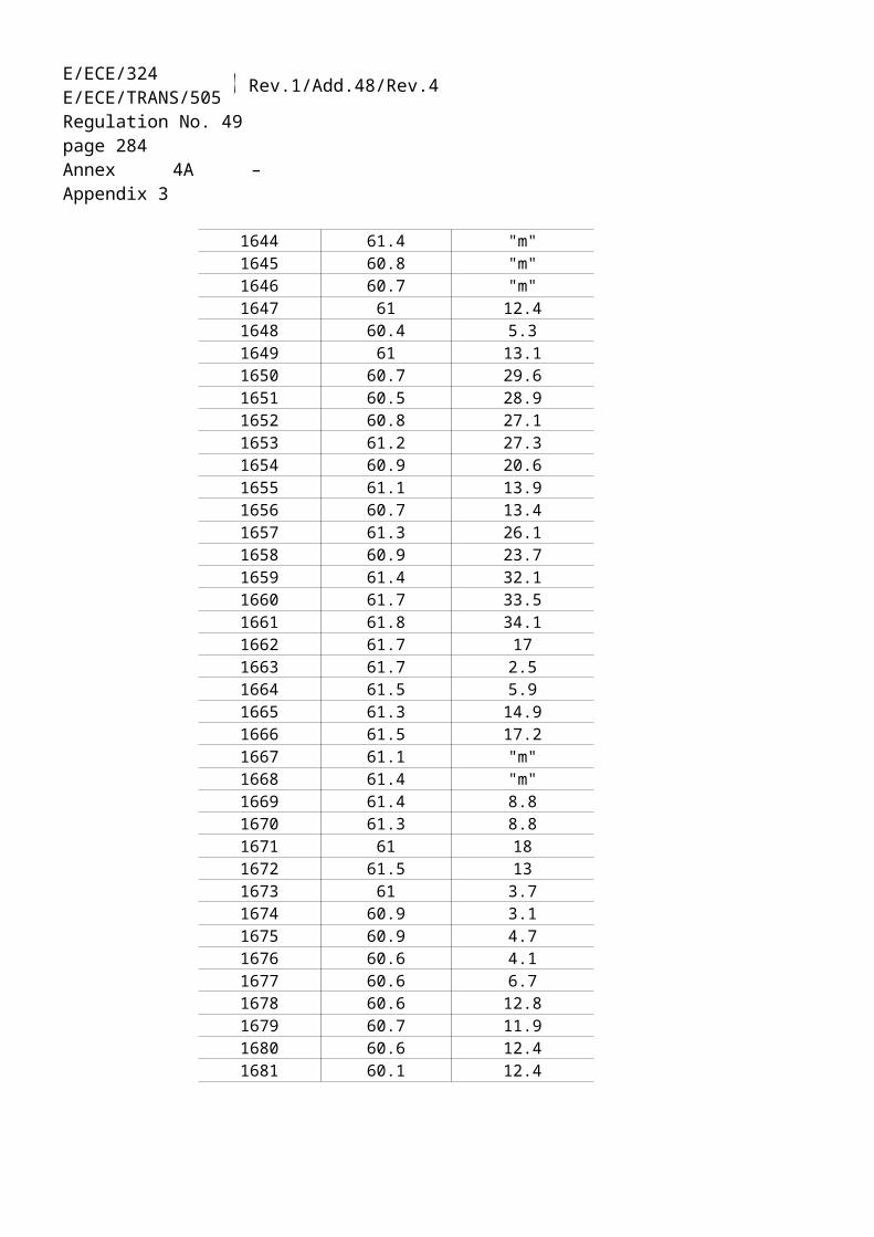
E/ECE/324E/ECE/TRANS/505 Rev.1/Add.48/Rev.4
Regulation No. 49page 284Annex 4B
7.6.1.1. Determination of preferred speed
From the engine mapping curve as determined in accordance with paragraph 7.5.2., the integral of the maximum torque shall be calculated from nidle to n95h. n95h is the highest speed where the power is 95 per cent of maximum power. npref is then defined as the speed that corresponds to 51 per cent of the whole integral, as shown in figure 5.
60,0%
80,0%
100,0%
Engine Speed
Engi
ne T
orqu
e
n idle n 95hn pref
Area = 100 %Area = 51 %
Figure 5:Definition of npref
7.6.2. Denormalization of engine torque
The torque values in the engine dynamometer schedule of Appendix 1 are normalized to the maximum torque at the respective speed. The torque values of the reference cycle shall be denormalized, using the mapping curve determined according to paragraph 7.5.2., as follows:
Actual torque = (5)
for the respective actual speed as determined in paragraph 7.6.1.
7.6.3. Example of denormalization procedure
As an example, the following test point shall be denormalized:

ECE/TR
AN
S/WP.29/2007/26
page 487
E/ECE/324E/ECE/TRANS/505 Rev.1/Add.48/Rev.4
Regulation No. 49page 285Annex 4B
per cent speed = 43 per centper cent torque = 82 per cent
Given the following values:
nlo = 1,015 min-1
nhi = 2,200 min-1
npref = 1,300 min-1
nidle = 600 min-1
results in:
actual speed =
= 1,178 min-1
With the maximum torque of 700 Nm observed from the mapping curve at 1,178 min-1
actual torque = = 574 Nm
7.7. Validation of the test run
7.7.1. Calculation of the cycle work
Before calculating the cycle work, any points recorded during engine starting shall be omitted. The cycle work Wact (kWh) shall be calculated based on engine feedback speed and torque values. The reference cycle work Wref (kWh) shall be calculated based on engine reference speed and torque values. The actual cycle work Wact is used for comparison to the reference cycle work Wref and for calculating the brake specific emissions (see paragraph 8.5.2.1.).
The same methodology shall be used for integrating both reference and actual engine power. If values are to be determined between adjacent reference or adjacent measured values, linear interpolation shall be used. In integrating the actual cycle work, any negative torque values shall be set equal to zero and included. If integration is performed at a frequency of less than 5 Hz, and if, during a given time segment, the torque value changes from positive to negative or negative to positive, the negative portion shall be computed and set equal to zero. The positive portion shall be included in the integrated value.
Wact shall be between 85 per cent and 105 per cent of Wref.

E/ECE/324E/ECE/TRANS/505 Rev.1/Add.48/Rev.4
Regulation No. 49page 286Annex 4B
7.7.2. Validation statistics of the test cycle
Linear regressions of the actual values on the reference values shall be performed for speed, torque and power.
To minimize the biasing effect of the time lag between the actual and reference cycle values, the entire engine speed and torque actual signal sequence may be advanced or delayed in time with respect to the reference speed and torque sequence. If the actual signals are shifted, both speed and torque must be shifted the same amount in the same direction.
The method of least squares shall be used, with the best fit equation having the form:
y = mx + b (6)
where:y = actual value of speed (min-1), torque (Nm), or power (kW)m = slope of the regression linex = reference value of speed (min-1), torque (Nm), or power (kW)b = y intercept of the regression line
The standard error of estimate (SEE) of y on x and the coefficient of determination (r²) shall be calculated for each regression line.
It is recommended that this analysis be performed at 1 Hz. For a test to be considered valid, the criteria of table 2 shall be met.
Speed Torque PowerStandard error of estimate (SEE) of y on x
max. 100 min-1 max. 13 per cent of maximum engine torque
max. 8 per cent of maximum engine power
Slope of the regression line, m
0.95 to 1.03 0.83 - 1.03 0.89 - 1.03
Coefficient of determination, r²
min. 0.970 min. 0.850 min. 0.910
y intercept of the regression line, b
± 50 min-1 ± 20 Nm or 2 per cent of max. torque whichever is greater
± 4 kW or 2 per cent of max. power whichever is greater
Table 2:Regression line tolerances
For regression purposes only, point deletions are permitted where noted in table 3 before doing the regression calculation. However, those points shall not be deleted

ECE/TR
AN
S/WP.29/2007/26
page 487
E/ECE/324E/ECE/TRANS/505 Rev.1/Add.48/Rev.4
Regulation No. 49page 287Annex 4B
for the calculation of cycle work and emissions. An idle point is defined as a point having a normalized reference torque of 0 per cent and a normalized reference speed of 0 per cent. Point deletion may be applied to the whole or to any part of the cycle.
Condition Points to be deletedFirst 6 1 seconds Speed, torque, powerFull load demand and actual torque 95 per cent reference torque
Torque and/or power
Full load demand and actual speed 95 per cent reference speed
Speed and/or power
No load demand and actual torque reference torque Torque and/or powerNo load demand and actual torque > 2 per cent of max. torque (idle point)
Speed and/or power
No load demand and reference torque < 0 per cent (motoring point)
Torque and/or power
Table 3:Permitted point deletions from regression analysis
7.8. Emissions Test Run
7.8.1. Introduction
The emissions to be measured from the exhaust of the engine include the gaseous components (carbon monoxide, total hydrocarbons or non-methane hydrocarbons, methane and oxides of nitrogen), and the particulates. Additionally, carbon dioxide is often used as a tracer gas for determining the dilution ratio of partial and full flow dilution systems.
The above pollutants shall be examined during the prescribed test cycles. The concentrations of the gaseous components shall be determined over the cycle either in the raw exhaust gas by integration of the analyzer signal, or in the diluted exhaust gas of a CVS full flow dilution system by integration or by bag sampling. For particulates, a proportional sample shall be collected from the diluted exhaust gas on a specified filter by either partial flow dilution or full flow dilution. Depending on the method used, the diluted or undiluted exhaust gas flow rate shall be determined over the cycle to calculate the mass emission values of the pollutants. The mass emission values shall be related to the engine work, as calculated in accordance with paragraph 7.7.1., to get the grams of each pollutant emitted per kilowatt hour.
7.8.2. Pre-test procedures
Pre-test engine measurements, pre-test engine performance checks and pre-test system calibrations shall be made prior to the engine mapping procedure in line with general sequence shown in paragraph 7.4.

E/ECE/324E/ECE/TRANS/505 Rev.1/Add.48/Rev.4
Regulation No. 49page 288Annex 4B
7.8.2.1. Engine cool-down (cold start test only)
A natural or forced cool-down procedure may be applied. For forced cool-down, good engineering judgment shall be used to set up systems to send cooling air across the engine, to send cool oil through the engine lubrication system, to remove heat from the coolant through the engine cooling system, and to remove heat from an exhaust after-treatment system. In the case of a forced after-treatment system cool down, cooling air shall not be applied until the after-treatment system has cooled below its catalytic activation temperature. Any cooling procedure that results in unrepresentative emissions is not permitted.
7.8.2.2. Preparation of the particulate sampling filter
At least one hour before the test, each filter shall be placed in a petri dish, which is protected against dust contamination and allows air exchange, and placed in a weighing chamber for stabilization. At the end of the stabilization period, each filter shall be weighed and the tare weight shall be recorded. The filter shall then be stored in a closed petri dish or sealed filter holder until needed for testing. The filter shall be used within eight hours of its removal from the weighing chamber.
7.8.2.3. Installation of the measuring equipment
The instrumentation and sample probes shall be installed as required. The tailpipe shall be connected to the full flow dilution system, if used.
7.8.2.4. Preconditioning the dilution system and the engine (WHSC only)
The dilution system and the engine shall be started and warmed up. After warm-up, the engine and sampling system shall be preconditioned by operating the engine at mode 9 for a minimum of 10 minutes while simultaneously operating either the partial flow dilution system or the full flow dilution and secondary dilution system. Dummy particulate emissions samples may be collected. Those sample filters need not be stabilized or weighed, and may be discarded. Flow rates shall be set at the approximate flow rates selected for testing.
7.8.2.5. Starting the particulate sampling system
The particulate sampling system shall be started and operated on by-pass. The particulate background level of the dilution air may be determined by sampling the dilution air prior to the entrance of the exhaust gas into the dilution tunnel. The measurement may be done prior to or after the test. If the measurement is done both at the beginning and at the end of the cycle, the values may be averaged. If a
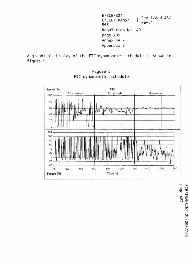
ECE/TR
AN
S/WP.29/2007/26
page 487
E/ECE/324E/ECE/TRANS/505 Rev.1/Add.48/Rev.4
Regulation No. 49page 289Annex 4B
different sampling system is used for background measurement, the measurement shall be done in parallel to the test run.
7.8.2.6. Adjustment of the dilution system
The total diluted exhaust gas flow of a full flow dilution system or the diluted exhaust gas flow through a partial flow dilution system shall be set to eliminate water condensation in the system, and to obtain a filter face temperature between 315 K (42 °C) and 325 K (52 °C).
7.8.2.7. Checking the analyzers
The emission analyzers shall be set at zero and spanned. If sample bags are used, they shall be evacuated.
7.8.3. Engine starting procedure
7.8.3.1. Cold start test (WHTC only)
The cold-start test shall be started when the temperatures of the engine's lubricant, coolant, and after-treatment systems are all between 293 and 303 K (20 and 30 °C). The engine shall be started using one of the following methods:(a) The engine shall be started as recommended in the owners manual using a
production starter motor and adequately charged battery or a suitable power supply; or
(b) The engine shall be started by using the dynamometer. The engine shall be motored within 25 per cent of its typical in-use cranking speed. Cranking shall be stopped within 1 second of starting the engine. If the engine does not start after 15 seconds of cranking, cranking shall be stopped and the reason for the failure to start determined, unless the owners manual or the service-repair manual describes the longer cranking time as normal.
7.8.3.2. Hot soak period (WHTC only)
Immediately upon completion of the cold start test, the engine shall be soaked for 5 + 1 minutes.
7.8.3.3. Hot start test
7.8.3.3.1. WHTC
The engine shall be started at the end of the hot soak period as defined in paragraph 7.8.3.2. using the procedures given in paragraph 7.8.3.1.

E/ECE/324E/ECE/TRANS/505 Rev.1/Add.48/Rev.4
Regulation No. 49page 290Annex 4B
7.8.3.3.2. WHSC
Five minutes after completion of preconditioning at mode 9 as described in paragraph 7.8.2.4., the engine shall be started according to the manufacturer's recommended starting procedure in the owner's manual, using either a production starter motor or the dynamometer in accordance with paragraph 7.8.3.1.
7.8.4. Cycle run
The general requirements laid down in this paragraph apply to both, the cold start test referred to in paragraph 7.8.3.1. and to the hot start test referred to in paragraph 7.8.3.3.
7.8.4.1. Test sequence
The test sequence shall commence at the start of the engine.
The WHTC shall be performed according to the reference cycle as set out in paragraph 7.2. Engine speed and torque command set points shall be issued at 5 Hz (10 Hz recommended) or greater. The set points shall be calculated by linear interpolation between the 1 Hz set points of the reference cycle. Actual engine speed and torque shall be recorded at least once every second during the test cycle (1 Hz), and the signals may be electronically filtered.
The WHSC shall be performed according to the order of test modes listed in table 1 of paragraph 7.3.
7.8.4.2. Analyzer response
At the start of the test sequence, the measuring equipment shall be started, simultaneously:(a) start collecting or analyzing dilution air, if a full flow dilution system is used;(b) start collecting or analyzing raw or diluted exhaust gas, depending on the
method used;(c) start measuring the amount of diluted exhaust gas and the required temperatures
and pressures;(d) start recording the exhaust gas mass flow rate, if raw exhaust gas analysis is
used;(e) start recording the feedback data of speed and torque of the dynamometer.
If raw exhaust measurement is used, the emission concentrations ((NM)HC, CO and NOx) and the exhaust gas mass flow rate shall be measured continuously and stored with at least 2 Hz on a computer system. All other data may be recorded with a
ECE/TR
AN
S/WP.29/2007/26
page 487
E/ECE/324E/ECE/TRANS/505 Rev.1/Add.48/Rev.4
Regulation No. 49page 291Annex 4B
sample rate of at least 1 Hz. For analogue analyzers the response shall be recorded, and the calibration data may be applied online or offline during the data evaluation.
If a full flow dilution system is used, HC and NOx shall be measured continuously in the dilution tunnel with a frequency of at least 2 Hz. The average concentrations shall be determined by integrating the analyzer signals over the test cycle. The system response time shall be no greater than 20 s, and shall be coordinated with CVS flow fluctuations and sampling time/test cycle offsets, if necessary. CO, CO2, and NMHC may be determined by integration of continuous measurement signals or by analyzing the concentrations in the sample bag, collected over the cycle. The concentrations of the gaseous pollutants in the dilution air shall be determined by integration or by collecting into the background bag. All other parameters that need to be measured shall be recorded with a minimum of one measurement per second (1 Hz).
7.8.4.3. Particulate sampling
At the start of the test sequence, the particulate sampling system shall be switched from by-pass to collecting particulates.
If a partial flow dilution system is used, the sample pump(s) shall be controlled , so that the flow rate through the particulate sample probe or transfer tube is maintained proportional to the exhaust mass flow rate as determined in accordance with paragraph 8.3.3.3.
If a full flow dilution system is used, the sample pump(s) shall be adjusted so that the flow rate through the particulate sample probe or transfer tube is maintained at a value within ± 2.5 per cent of the set flow rate. If flow compensation (i.e., proportional control of sample flow) is used, it must be demonstrated that the ratio of main tunnel flow to particulate sample flow does not change by more than ± 2.5 per cent of its set value (except for the first 10 seconds of sampling). The average temperature and pressure at the gas meter(s) or flow instrumentation inlet shall be recorded. If the set flow rate cannot be maintained over the complete cycle within ± 2.5 per cent because of high particulate loading on the filter, the test shall be voided. The test shall be rerun using a lower sample flow rate.
7.8.4.4. Engine stalling and equipment malfunction
If the engine stalls anywhere during the cold start test of the WHTC or during the WHSC, the test shall be voided. The engine shall be preconditioned and restarted according to the starting methods of paragraph 7.8.3.1., and the test repeated.

E/ECE/324E/ECE/TRANS/505 Rev.1/Add.48/Rev.4
Regulation No. 49page 292Annex 4B
If the engine stalls anywhere during the hot start test of the WHTC, the test shall be voided. The engine shall be soaked according to paragraph 7.8.3.2., and the hot start test repeated. In this case, the cold start test need not be repeated.
If a malfunction occurs in any of the required test equipment during the test cycle, the test shall be voided and repeated in line with the above provisions in dependence of the test cycle.
7.8.4.5. Operations after test
At the completion of the test, the measurement of the exhaust gas mass flow rate, the diluted exhaust gas volume, the gas flow into the collecting bags and the particulate sample pump shall be stopped. For an integrating analyzer system, sampling shall continue until system response times have elapsed.
The concentrations of the collecting bags, if used, shall be analysed as soon as possible and in any case not later than 20 minutes after the end of the test cycle.
After the emission test, a zero gas and the same span gas shall be used for re-checking the analyzers. The test will be considered acceptable if the difference between the pre-test and post-test results is less than 2 per cent of the span gas value.
The particulate filter shall be returned to the weighing chamber no later than one hour after completion of the test. It shall be conditioned in a petri dish, which is protected against dust contamination and allows air exchange, for at least one hour, and then weighed. The gross weight of the filter shall be recorded.
8. EMISSION MEASUREMENT AND CALCULATION
The final test result shall be rounded in one step to the number of places to the right of the decimal point indicated by the applicable emission standard plus one additional significant figure, in accordance with ASTM E 29-04. No rounding of intermediate values leading to the final break-specific emission result is permitted.
8.1. Dry/wet correction
If the emissions are measured on a dry basis, the measured concentration shall be converted to a wet basis according to the following equation:
(7)
where:cw is the wet concentration in ppm or per cent volumecd is the dry concentration in ppm or per cent volume
ECE/TR
AN
S/WP.29/2007/26
page 487
E/ECE/324E/ECE/TRANS/505 Rev.1/Add.48/Rev.4
Regulation No. 49page 293Annex 4B
kw is the dry/wet correction factor
8.1.1. Raw exhaust gas
kw,a = (8)
or
kw,a = (9)
or
(10)
with
kf = 0.055594 x wALF + 0.0080021 x wDEL + 0.0070046 x wEPS (11)
and
kw1 = (12)
where:Ha is the intake air humidity, g water per kg dry airwALF is the hydrogen content of the fuel, per cent massqmf,i is the instantaneous fuel mass flow rate, kg/sqmad,I is the instantaneous dry intake air mass flow rate, kg/s pr is the water vapour pressure after cooling bath, kPapb is the total atmospheric pressure, kPawDEL is the nitrogen content of the fuel, per cent mass
E/ECE/324E/ECE/TRANS/505 Rev.1/Add.48/Rev.4
Regulation No. 49page 294Annex 4B
wEPS is the oxygen content of the fuel, per cent mass is the molar hydrogen ratio of the fuelcCO2 is the dry CO2 concentration, per centcCO is the dry CO concentration, per cent
Equations (8) and (9) are principally identical with the factor 1.008 in equations (8) and (10) being an approximation for the more accurate denominator in equation (9).
8.1.2. Diluted exhaust gas
(13)
or
(14)
with
(15)
where: is the molar hydrogen ratio of the fuelcCO2w is the wet CO2 concentration, per centcCO2d is the dry CO2 concentration, per centHd is the dilution air humidity, g water per kg dry airHa is the intake air humidity, g water per kg dry airD is the dilution factor (see paragraph 8.4.2.4.2.)
8.1.3. Dilution air
(16)

ECE/TR
AN
S/WP.29/2007/26
page 487
E/ECE/324E/ECE/TRANS/505 Rev.1/Add.48/Rev.4
Regulation No. 49page 295Annex 4B
with
(17)
where:Hd is the dilution air humidity, g water per kg dry air
8.2. NOx correction for humidity
As the NOx emission depends on ambient air conditions, the NOx concentration shall be corrected for humidity with the factors given in paragraph 8.2.1. or 8.2.2. The intake air humidity Ha may be derived from relative humidity measurement, dew point measurement, vapour pressure measurement or dry/wet bulb measurement using generally accepted equation.
8.2.1. Compression-ignition engines
(18)
where:Ha is the intake air humidity, g water per kg dry air
8.2.2. Positive ignition engines
kh.G = 0.6272 + 44.030 x 10⁻³ x Ha – 0.862 x 10⁻³ x Ha² (19)
where:Ha is the intake air humidity, g water per kg dry air
8.3. Partial flow dilution (PFS) and raw gaseous measurement
The instantaneous concentration signals of the gaseous components are used for the calculation of the mass emissions by multiplication with the instantaneous exhaust mass flow rate. The exhaust mass flow rate may be measured directly, or calculated using the methods of intake air and fuel flow measurement, tracer method or intake air and air/fuel ratio measurement. Special attention shall be paid to the response times of the different instruments. These differences shall be accounted for by time aligning the signals. For particulates, the exhaust mass flow rate signals are used for controlling the partial flow dilution system to take a sample proportional to the exhaust mass flow rate. The quality of proportionality shall be checked by applying a regression analysis between sample and exhaust flow in accordance with paragraph 8.3.3.3. The complete test set up is schematically shown in figure 6.

E/ECE/324E/ECE/TRANS/505 Rev.1/Add.48/Rev.4
Regulation No. 49page 296Annex 4B
Figure 6:Scheme of raw/partial flow measurement system
8.3.1. Determination of exhaust gas mass flow
8.3.1.1. Introduction
For calculation of the emissions in the raw exhaust gas and for controlling of a partial flow dilution system, it is necessary to know the exhaust gas mass flow rate. For the determination of the exhaust mass flow rate, either of the methods described in paragraphs 8.3.1.3. to 8.3.1.6. may be used.
8.3.1.2. Response time
For the purpose of emissions calculation, the response time of either method described in paragraphs 8.3.1.3. to 8.3.1.6. shall be equal to or less than the analyzer response time of ≤ 10 s, as required in paragraph 9.3.5.
For the purpose of controlling of a partial flow dilution system, a faster response is required. For partial flow dilution systems with online control, the response time shall be ≤ 0.3 s. For partial flow dilution systems with look ahead control based on a pre-recorded test run, the response time of the exhaust flow measurement system shall be ≤ 5 s with a rise time of ≤ 1 s. The system response time shall be specified
ECE/TR
AN
S/WP.29/2007/26
page 487
E/ECE/324E/ECE/TRANS/505 Rev.1/Add.48/Rev.4
Regulation No. 49page 297Annex 4B
by the instrument manufacturer. The combined response time requirements for the exhaust gas flow and partial flow dilution system are indicated in paragraph 8.3.3.3.
8.3.1.3. Direct measurement method
Direct measurement of the instantaneous exhaust flow shall be done by systems, such as:(a)pressure differential devices, like flow nozzle, (details see ISO 5167)(b)ultrasonic flowmeter(c)vortex flowmeter
Precautions shall be taken to avoid measurement errors which will impact emission value errors. Such precautions include the careful installation of the device in the engine exhaust system according to the instrument manufacturers' recommendations and to good engineering practice. Especially, engine performance and emissions shall not be affected by the installation of the device.
The flow meters shall meet the linearity requirements of paragraph 9.2.
8.3.1.4. Air and fuel measurement method
This involves measurement of the airflow and the fuel flow with suitable flowmeters. The calculation of the instantaneous exhaust gas flow shall be as follows:
qmew,i = qmaw,i + qmf,i (20)
where:q
mew,i is the instantaneous exhaust mass flow rate, kg/sq
maw,i is the instantaneous intake air mass flow rate, kg/sq
mf,i is the instantaneous fuel mass flow rate, kg/s
The flow meters shall meet the linearity requirements of paragraph 9.2., but shall be accurate enough to also meet the linearity requirements for the exhaust gas flow.
8.3.1.5. Tracer measurement method
This involves measurement of the concentration of a tracer gas in the exhaust.
A known amount of an inert gas (e.g. pure helium) shall be injected into the exhaust gas flow as a tracer. The gas is mixed and diluted by the exhaust gas, but shall not react in the exhaust pipe. The concentration of the gas shall then be measured in the exhaust gas sample.

E/ECE/324E/ECE/TRANS/505 Rev.1/Add.48/Rev.4
Regulation No. 49page 298Annex 4B
In order to ensure complete mixing of the tracer gas, the exhaust gas sampling probe shall be located at least 1 m or 30 times the diameter of the exhaust pipe, whichever is larger, downstream of the tracer gas injection point. The sampling probe may be located closer to the injection point if complete mixing is verified by comparing the tracer gas concentration with the reference concentration when the tracer gas is injected upstream of the engine.
The tracer gas flow rate shall be set so that the tracer gas concentration at engine idle speed after mixing becomes lower than the full scale of the trace gas analyzer.
The calculation of the exhaust gas flow shall be as follows:
(21)
where:q
mew,i is the instantaneous exhaust mass flow rate, kg/sqvt is tracer gas flow rate, cm³/mincmix,i is the instantaneous concentration of the tracer gas after mixing, ppme is the density of the exhaust gas, kg/m³ (cf. table 4)cb is the background concentration of the tracer gas in the intake air, ppm
The background concentration of the tracer gas (cb) may be determined by averaging the background concentration measured immediately before the test run and after the test run.
When the background concentration is less than 1 per cent of the concentration of the tracer gas after mixing (cmix.i) at maximum exhaust flow, the background concentration may be neglected.
The total system shall meet the linearity requirements for the exhaust gas flow of paragraph 9.2.
8.3.1.6. Airflow and air to fuel ratio measurement method
This involves exhaust mass calculation from the airflow and the air to fuel ratio. The calculation of the instantaneous exhaust gas mass flow is as follows:
(22)
ECE/TR
AN
S/WP.29/2007/26
page 487
E/ECE/324E/ECE/TRANS/505 Rev.1/Add.48/Rev.4
Regulation No. 49page 299Annex 4B
with
(23)
(24)
where:q
mew,i is the instantaneous exhaust mass flow rate, kg/sq
maw,i is the instantaneous intake air mass flow rate, kg/sA/Fst is the stoichiometric air to fuel ratio, kg/kgi is the instantaneous excess air ratiocCO2d is the dry CO2 concentration, per centcCOd is the dry CO concentration, ppmcHCw is the wet HC concentration, ppm
Air flowmeter and analyzers shall meet the linearity requirements of paragraph 9.2., and the total system shall meet the linearity requirements for the exhaust gas flow of paragraph 9.2.
If an air to fuel ratio measurement equipment such as a zirconia type sensor is used for the measurement of the excess air ratio, it shall meet the specifications of paragraph 9.3.2.7.
8.3.2. Determination of the gaseous components
8.3.2.1. Introduction
The gaseous components in the raw exhaust gas emitted by the engine submitted for testing shall be measured with the measurement and sampling systems described in paragraph 9.3. and Appendix 3. The data evaluation is described in paragraph 8.3.2.3.

E/ECE/324E/ECE/TRANS/505 Rev.1/Add.48/Rev.4
Regulation No. 49page 300Annex 4B
Two calculation procedures are described in paragraphs 8.3.2.4. and 8.3.2.5., which are equivalent for the reference fuels of Appendix 2. The procedure in paragraph 8.3.2.4. is more straightforward, since it uses tabulated u values for the ratio between component and exhaust gas density. The procedure in paragraph 8.3.2.5. is more accurate for fuel qualities that deviate from the specifications in Appendix 2, but requires elementary analysis of the fuel composition.
8.3.2.2. Sampling for gaseous emissions
The gaseous emissions sampling probes shall be fitted at least 0.5 m or 3 times the diameter of the exhaust pipe - whichever is the larger - upstream of the exit of the exhaust gas system but sufficiently close to the engine as to ensure an exhaust gas temperature of at least 343 K (70 °C) at the probe.
In the case of a multi-cylinder engine with a branched exhaust manifold, the inlet of the probe shall be located sufficiently far downstream so as to ensure that the sample is representative of the average exhaust emissions from all cylinders. In multi-cylinder engines having distinct groups of manifolds, such as in a "Vee" engine configuration, it is recommended to combine the manifolds upstream of the sampling probe. If this is not practical, it is permissible to acquire a sample from the group with the highest CO2 emission. For exhaust emission calculation the total exhaust mass flow shall be used.
If the engine is equipped with an exhaust after-treatment system, the exhaust sample shall be taken downstream of the exhaust after-treatment system.
8.3.2.3. Data evaluation
For the evaluation of the gaseous emissions, the raw emission concentrations (HC, CO and NOx) and the exhaust gas mass flow rate shall be recorded and stored with at least 2 Hz on a computer system. All other data shall be recorded with a sample rate of at least 1 Hz. For analogue analyzers, the response shall be recorded, and the calibration data may be applied online or offline during the data evaluation.
For calculation of the mass emission of the gaseous components, the traces of the recorded concentrations and the trace of the exhaust gas mass flow rate shall be time aligned by the transformation time as defined in paragraph 3.1.28. Therefore, the response time of each gaseous emissions analyzer and of the exhaust gas mass flow system shall be determined according to paragraphs 8.3.1.2 and 9.3.5., respectively, and recorded.
8.3.2.4. Calculation of mass emission based on tabulated values

ECE/TR
AN
S/WP.29/2007/26
page 487
E/ECE/324E/ECE/TRANS/505 Rev.1/Add.48/Rev.4
Regulation No. 49page 301Annex 4B
The mass of the pollutants (g/test) shall be determined by calculating the instantaneous mass emissions from the raw concentrations of the pollutants and the exhaust gas mass flow, aligned for the transformation time as determined in accordance with paragraph 8.3.2.3., integrating the instantaneous values over the cycle, and multiplying the integrated values with the u values from table 4. If measured on a dry basis, the dry/wet correction according to paragraph 8.1. shall be applied to the instantaneous concentration values before any further calculation is done.
For the calculation of NOx, the mass emission shall be multiplied with the humidity correction factor kh,D, or kh,G, as determined according to paragraph 8.2.
An example of the calculation procedures is given in Appendix 6.
The following equation shall be applied:
mgas = (in g/test) (25)
where:ugas is the ratio between density of exhaust component and density of exhaust
gascgas,i is the instantaneous concentration of the component in the exhaust gas,
ppmqmew,i is the instantaneous exhaust mass flow, kg/sf is the data sampling rate, Hzn is the number of measurements
Fuel e
GasNOx CO HC CO2 O2 CH4
gas [kg/m3]2.053 1.250 a) 1.9636 1.4277 0.716
ugasb)
Diesel 1.2943 0.001586 0.000966 0.000479 0.001517 0.001103 0.000553Ethanol 1.2757 0.001609 0.000980 0.000805 0.001539 0.001119 0.000561CNGc) 1.2661 0.001621 0.000987 0.000558d) 0.001551 0.001128 0.000565Propane 1.2805 0.001603 0.000976 0.000512 0.001533 0.001115 0.000559Butane 1.2832 0.001600 0.000974 0.000505 0.001530 0.001113 0.000558LPGe) 1.2811 0.001602 0.000976 0.000510 0.001533 0.001115 0.000559a) depending on fuelb) at = 2, dry air, 273 K, 101.3 kPac) u accurate within 0.2 % for mass composition of: C = 66 - 76 %; H = 22 - 25 %; N = 0 - 12 % d) NMHC on the basis of CH2.93 (for total HC the ugas coefficient of CH4 shall be used)e) u accurate within 0.2 % for mass composition of: C3 = 70 - 90 %; C4 = 10 - 30 %
Table 4:Raw exhaust gas u values and component densities

E/ECE/324E/ECE/TRANS/505 Rev.1/Add.48/Rev.4
Regulation No. 49page 302Annex 4B
8.3.2.5. Calculation of mass emission based on exact equations
The mass of the pollutants (g/test) shall be determined by calculating the instantaneous mass emissions from the raw concentrations of the pollutants, the u values and the exhaust gas mass flow, aligned for the transformation time as determined in accordance with paragraph 8.3.2.3. and integrating the instantaneous values over the cycle. If measured on a dry basis, the dry/wet correction according to paragraph 8.1. shall be applied to the instantaneous concentration values before any further calculation is done.
For the calculation of NOx, the mass emission shall be multiplied with the humidity correction factor kh,D, or kh,G, as determined according to paragraph 8.2.
The following equation shall be applied:
mgas = (in g/test) (26)
where:ugas,i is the instantaneous density ratio of exhaust component and exhaust gascgas,i is the instantaneous concentration of the component in the exhaust gas,
ppmqmew,i is the instantaneous exhaust mass flow, kg/sf is the data sampling rate, Hzn is the number of measurements
The instantaneous u values shall be calculated as follows:
ugas,i = Mgas / (Me,i x 1,000) (27)
or
ugas,i =gas / (e,i x 1,000) (28)
with
gas = Mgas / 22.414 (29)
where:Mgas is the molar mass of the gas component, g/mol (cf. Appendix 6)Me,i is the instantaneous molar mass of the exhaust gas, g/molgas is the density of the gas component, kg/m3
e,i is the instantaneous density of the exhaust gas, kg/m3
ECE/TR
AN
S/WP.29/2007/26
page 487
E/ECE/324E/ECE/TRANS/505 Rev.1/Add.48/Rev.4
Regulation No. 49page 303Annex 4B
The molar mass of the exhaust, Me, shall be derived for a general fuel composition CHONSunder the assumption of complete combustion, as follows:
(30)
where:q
maw,i is the instantaneous intake air mass flow rate on wet basis, kg/sq
mf,i is the instantaneous fuel mass flow rate, kg/sHa is the intake air humidity, g water per kg dry airMa is the molar mass of the dry intake air = 28.965 g/mol
The exhaust density e shall be derived, as follows:
(31)
where:q
mad,i is the instantaneous intake air mass flow rate on dry basis, kg/sq
mf,i is the instantaneous fuel mass flow rate, kg/sHa is the intake air humidity, g water per kg dry airkf is the fuel specific factor according to equation 11 in paragraph 8.1.1.
8.3.3. Particulate determination
8.3.3.1. Introduction
The determination of the particulates requires dilution of the sample with filtered ambient air, synthetic air or nitrogen. The partial flow dilution system shall be set to completely eliminate water condensation in the dilution and sampling systems, and maintain the temperature of the diluted exhaust gas between 315 K (42 °C) and 325 K (52 °C) immediately upstream of the filter holders. Dehumidifying the dilution air before entering the dilution system is permitted, and especially useful if dilution air humidity is high. The temperature of the dilution air shall be > 288 K (15 °C) in close proximity to the entrance into the dilution tunnel.

E/ECE/324E/ECE/TRANS/505 Rev.1/Add.48/Rev.4
Regulation No. 49page 304Annex 4B
The partial flow dilution system has to be designed to extract a proportional raw exhaust sample from the engine exhaust stream, thus responding to excursions in the exhaust stream flow rate, and introduce dilution air to this sample to achieve a temperature between 315 K (42 °C) and 325 K (52 °C) at the test filter. For this it is essential that the dilution ratio or the sampling ratio rd or rs be determined such that the accuracy requirements of paragraph 9.4.4. are fulfilled.
To determine the mass of the particulates, a particulate sampling system, a particulate sampling filter, a microgram balance, and a temperature and humidity controlled weighing chamber, are required. The details of the system are described in paragraph 9.4.
8.3.3.2. Particulate sampling
In general, the particulate sampling probe shall be installed in close proximity to the gaseous emissions sampling probe, but sufficiently distant as to not cause interference. Therefore, the installation provisions of paragraph 8.3.2.2. also apply to particulate sampling. The sampling line shall conform to the requirements laid down in Appendix 3.
In the case of a multi-cylinder engine with a branched exhaust manifold, the inlet of the probe shall be located sufficiently far downstream so as to ensure that the sample is representative of the average exhaust emissions from all cylinders. In multi-cylinder engines having distinct groups of manifolds, such as in a "Vee" engine configuration, it is recommended to combine the manifolds upstream of the sampling probe. If this is not practical, it is permissible to acquire a sample from the group with the highest particulate emission. For exhaust emission calculation the total exhaust mass flow of the manifold shall be used.
8.3.3.3. System response time
For the control of a partial flow dilution system, a fast system response is required. The transformation time for the system shall be determined by the procedure in paragraph 9.4.7.3. If the combined transformation time of the exhaust flow measurement (see paragraph 8.3.1.2.) and the partial flow system is < 0.3 s, online control shall be used. If the transformation time exceeds 0.3 s, look ahead control based on a pre-recorded test run shall be used. In this case, the combined rise time shall be 1 s and the combined delay time 10 s.
The total system response shall be designed as to ensure a representative sample of the particulates, qmp,i, proportional to the exhaust mass flow. To determine the proportionality, a regression analysis of qmp,i versus qmew,i shall be conducted on a minimum 5 Hz data acquisition rate, and the following criteria shall be met:

ECE/TR
AN
S/WP.29/2007/26
page 487
E/ECE/324E/ECE/TRANS/505 Rev.1/Add.48/Rev.4
Regulation No. 49page 305Annex 4B
(a) The coefficient of determination r2 of the linear regression between qmp,i and qmew,i shall not be less than 0.95
(b) The standard error of estimate of qmp,i on qmew,i shall not exceed 5 per cent of qmp
maximum.(c) qmp intercept of the regression line shall not exceed 2 per cent of qmp
maximum.
Look-ahead control is required if the combined transformation times of the particulate system, t50,P and of the exhaust mass flow signal, t50,F are > 0.3 s. In this case, a pre-test shall be run, and the exhaust mass flow signal of the pre-test be used for controlling the sample flow into the particulate system. A correct control of the partial dilution system is obtained, if the time trace of qmew,pre of the pre-test, which controls qmp, is shifted by a "look-ahead" time of t50,P + t50,F.
For establishing the correlation between qmp,i and qmew,i the data taken during the actual test shall be used, with qmew,i time aligned by t50,F relative to qmp,i (no contribution from t50,P to the time alignment). That is, the time shift between qmew and qmp is the difference in their transformation times that were determined in paragraph 9.4.7.3.
8.3.3.4. Data evaluation
The tare weight of the filter, as determined according to paragraph 7.8.2.2., shall be subtracted from the gross weight of the filter, as determined according to paragraph 7.8.4.5., which results in the particulate sample mass mf. For the evaluation of the particulate concentration, the total sample mass (msep) through the filter over the test cycle shall be recorded.
With the prior approval of the type Approval Authority, the particulate mass may be corrected for the particulate level of the dilution air, as determined in paragraph 7.8.2.5., in line with good engineering practice and the specific design features of the particulate measurement system used.
8.3.3.5. Calculation of mass emission
Depending on system design, the mass of particulates (g/test) shall be calculated by either of the methods in paragraphs 8.3.3.5.1. or 8.3.3.5.2. after buoyancy correction of the particulate sample mass according to paragraph 9.4.3.5. An example of the calculation procedures is given in Appendix 6.
8.3.3.5.1. Calculation based on sample ratio
mPM = mf / (rs x 1,000) (32)

E/ECE/324E/ECE/TRANS/505 Rev.1/Add.48/Rev.4
Regulation No. 49page 306Annex 4B
where:mf is the particulate mass sampled over the cycle, mgrs is the average sample ratio over the test cycle
with
rs = (33)
where:mse is the sample mass over the cycle, kgmew is the total exhaust mass flow over the cycle, kgmsep is the mass of diluted exhaust gas passing the particulate collection filters,
kgmsed is the mass of diluted exhaust gas passing the dilution tunnel, kg
In case of the total sampling type system, msep and msed are identical.
8.3.3.5.2. Calculation based on dilution ratio
mPM = (34)
where:mf is the particulate mass sampled over the cycle, mgmsep is the mass of diluted exhaust gas passing the particulate collection filters,
kgmedf is the mass of equivalent diluted exhaust gas over the cycle, kg
The total mass of equivalent diluted exhaust gas mass over the cycle shall be determined as follows:
medf = (35)
qmedf,I = qmew,i x rd,i (36)
rd,i = (37)
where:qmedf,i is the instantaneous equivalent diluted exhaust mass flow rate, kg/sqmew,i is the instantaneous exhaust mass flow rate, kg/srd,i is the instantaneous dilution ratio
ECE/TR
AN
S/WP.29/2007/26
page 487
E/ECE/324E/ECE/TRANS/505 Rev.1/Add.48/Rev.4
Regulation No. 49page 307Annex 4B
qmdew,i is the instantaneous diluted exhaust mass flow rate, kg/sqmdw,i is the instantaneous dilution air mass flow rate, kg/sf is the data sampling rate, Hzn is the number of measurements
8.4. Full flow dilution measurement (CVS)
The concentration signals, either by integration over the cycle or by bag sampling, of the gaseous components shall be used for the calculation of the mass emissions by multiplication with the diluted exhaust mass flow rate. The exhaust mass flow rate shall be measured with a constant volume sampling (CVS) system, which may use a positive displacement pump (PDP), a critical flow venturi (CFV) or a subsonic venturi (SSV) with or without flow compensation.
For bag sampling and particulate sampling, a proportional sample shall be taken from the diluted exhaust gas of the CVS system. For a system without flow compensation, the ratio of sample flow to CVS flow must not vary by more than ± 2.5 per cent from the set point of the test. For a system with flow compensation, each individual flow rate shall be constant within ± 2.5 per cent of its respective target flow rate.
The complete test set up is schematically shown in figure 7.
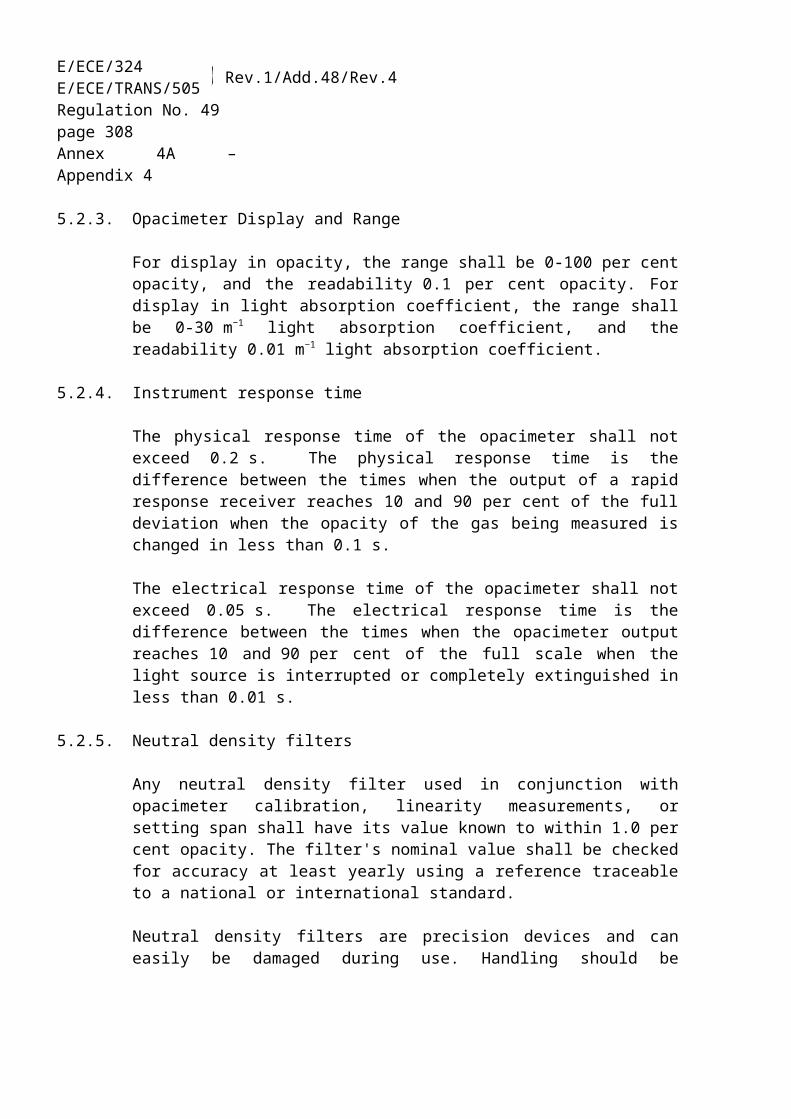
E/ECE/324E/ECE/TRANS/505 Rev.1/Add.48/Rev.4
Regulation No. 49page 308Annex 4B
Figure 7:Scheme of full flow measurement system
8.4.1. Determination of the diluted exhaust gas flow
8.4.1.1. Introduction
For calculation of the emissions in the diluted exhaust gas, it is necessary to know the diluted exhaust gas mass flow rate. The total diluted exhaust gas flow over the cycle (kg/test) shall be calculated from the measurement values over the cycle and the corresponding calibration data of the flow measurement device (V0 for PDP, KV
for CFV, Cd for SSV) by either of the methods described in paragraphs 8.4.1.2. to 8.4.1.4. If the total sample flow of particulates (msep) exceeds 0.5 per cent of the total CVS flow (med), the CVS flow shall be corrected for msep or the particulate sample flow shall be returned to the CVS prior to the flow measuring device.
8.4.1.2. PDP-CVS system
The calculation of the mass flow over the cycle is as follows, if the temperature of the diluted exhaust is kept within ± 6 K over the cycle by using a heat exchanger:
med = 1.293 x V0 x nP x pp x 273 / (101.3 x T) (38)

ECE/TR
AN
S/WP.29/2007/26
page 487
E/ECE/324E/ECE/TRANS/505 Rev.1/Add.48/Rev.4
Regulation No. 49page 309Annex 4B
where:V0 is the volume of gas pumped per revolution under test conditions, m³/revnP is the total revolutions of pump per testpp is the absolute pressure at pump inlet, kPaT is the average temperature of the diluted exhaust gas at pump inlet, K
If a system with flow compensation is used (i.e. without heat exchanger), the instantaneous mass emissions shall be calculated and integrated over the cycle. In this case, the instantaneous mass of the diluted exhaust gas shall be calculated as follows:
med,i = 1.293 x V0 x nP,i x pp x 273 / (101.3 x T) (39)
where:nP,i is the total revolutions of pump per time interval
8.4.1.3. CFV-CVS system
The calculation of the mass flow over the cycle is as follows, if the temperature of the diluted exhaust is kept within ± 11 K over the cycle by using a heat exchanger:
med = 1.293 x t x Kv x pp / T 0.5 (40)
where:t is the cycle time, sKV is the calibration coefficient of the critical flow venturi for standard conditions,pp is the absolute pressure at venturi inlet, kPaT is the absolute temperature at venturi inlet, K
If a system with flow compensation is used (i.e. without heat exchanger), the instantaneous mass emissions shall be calculated and integrated over the cycle. In this case, the instantaneous mass of the diluted exhaust gas shall be calculated as follows:
med,i = 1.293 x ti x KV x pp / T 0.5 (41)
where:ti is the time interval, s
8.4.1.4. SSV-CVS system
The calculation of the mass flow over the cycle shall be as follows, if the temperature of the diluted exhaust is kept within ± 11 K over the cycle by using a heat exchanger:

E/ECE/324E/ECE/TRANS/505 Rev.1/Add.48/Rev.4
Regulation No. 49page 310Annex 4B
med = 1.293 x QSSV (42)
with
(43)
where:
A0 is 0.006111 in SI units of
dV is the diameter of the SSV throat, mCd is the discharge coefficient of the SSVpp is the absolute pressure at venturi inlet, kPaT is the temperature at the venturi inlet, K
rp is the ratio of the SSV throat to inlet absolute static pressure,
rD is the ratio of the SSV throat diameter, d, to the inlet pipe inner diameter D
If a system with flow compensation is used (i.e. without heat exchanger), the instantaneous mass emissions shall be calculated and integrated over the cycle. In this case, the instantaneous mass of the diluted exhaust gas shall be calculated as follows:
med = 1.293 x QSSV x ti (44)
where:ti is the time interval, s
The real time calculation shall be initialized with either a reasonable value for Cd, such as 0.98, or a reasonable value of Qssv. If the calculation is initialized with Qssv, the initial value of Qssv shall be used to evaluate the Reynolds number.
During all emissions tests, the Reynolds number at the SSV throat shall be in the range of Reynolds numbers used to derive the calibration curve developed in paragraph 9.5.4.
8.4.2. Determination of the gaseous components

ECE/TR
AN
S/WP.29/2007/26
page 487
E/ECE/324E/ECE/TRANS/505 Rev.1/Add.48/Rev.4
Regulation No. 49page 311Annex 4B
8.4.2.1. Introduction
The gaseous components in the diluted exhaust gas emitted by the engine submitted for testing shall be measured by the methods described in Appendix 3. Dilution of the exhaust shall be done with filtered ambient air, synthetic air or nitrogen. The flow capacity of the full flow system shall be large enough to completely eliminate water condensation in the dilution and sampling systems. Data evaluation and calculation procedures are described in paragraphs 8.4.2.3. and 8.4.2.4.
8.4.2.2. Sampling for gaseous emissions
The exhaust pipe between the engine and the full flow dilution system shall conform to the requirements laid down in Appendix 3. The gaseous emissions sample probe(s) shall be installed in the dilution tunnel at a point where the dilution air and exhaust gas are well mixed, and in close proximity to the particulates sampling probe.
Sampling can generally be done in two ways:(a) the emissions are sampled into a sampling bag over the cycle and measured
after completion of the test; for HC, the sample bag shall be heated to 464 11 K (191 11°C), for NOx, the sample bag temperature shall be above the dew point temperature;
(b) the emissions are sampled continuously and integrated over the cycle.
The background concentrations shall be sampled upstream of the dilution tunnel into a sampling bag, and shall be subtracted from the emissions concentration according to paragraph 8.4.2.4.2.
8.4.2.3. Data evaluation
For continuous sampling, the emission concentrations (HC, CO and NOx) shall be recorded and stored with at least 1 Hz on a computer system, for bag sampling one mean value per test is required. The diluted exhaust gas mass flow rate and all other data shall be recorded with a sample rate of at least 1 Hz. For analogue analyzers the response will be recorded, and the calibration data may be applied online or offline during the data evaluation.
8.4.2.4. Calculation of mass emission
8.4.2.4.1. Systems with constant mass flow
For systems with heat exchanger, the mass of the pollutants shall be determined from the following equation:
E/ECE/324E/ECE/TRANS/505 Rev.1/Add.48/Rev.4
Regulation No. 49page 312Annex 4B
mgas = ugas x cgas x med (in g/test) (45)
where:ugas is the ratio between density of exhaust component and density of aircgas is the average background corrected concentration of the component, ppmmed is the total diluted exhaust mass over the cycle, kg
If measured on a dry basis, the dry/wet correction according to paragraph 8.1. shall be applied.
For the calculation of NOx, the mass emission shall be multiplied with the humidity correction factor kh,D, or kh,G, as determined according to paragraph 8.2.
The u values are given in table 5. For calculating the ugas values, the density of the diluted exhaust gas has been assumed to be equal to air density. Therefore, the ugas
values are identical for single gas components, but different for HC.
Alternatively, the exact equation method described in paragraph 8.3.2.5., equations 27 or 28 may be used.
Fuel de
GasNOx CO HC CO2 O2 CH4
gas
[kg/m3]2.053 1.250 a) 1.9636 1.4277 0.716
ugasb)
Diesel 1.293 0.001588 0.000967 0.000480 0.001519 0.001104 0.000553Ethanol 1.293 0.001588 0.000967 0.000795 0.001519 0.001104 0.000553CNGc) 1.293 0.001588 0.000967 0.000584d) 0.001519 0.001104 0.000553Propane 1.293 0.001588 0.000967 0.000507 0.001519 0.001104 0.000553Butane 1.293 0.001588 0.000967 0.000501 0.001519 0.001104 0.000553LPGe) 1.293 0.001588 0.000967 0.000505 0.001519 0.001104 0.000553a) depending on fuelb) at = 2, dry air, 273 K, 101.3 kPac) u accurate within 0.2 % for mass composition of: C = 66 - 76 %; H = 22 - 25 %; N = 0 - 12 % d) NMHC on the basis of CH2.93 (for total HC the ugas coefficient of CH4 shall be used)e) u accurate within 0.2 % for mass composition of: C3 = 70 - 90 %; C4 = 10 - 30 %
Table 5:Diluted exhaust gas u values and component densities
8.4.2.4.2. Determination of the background corrected concentrations
The average background concentration of the gaseous pollutants in the dilution air shall be subtracted from measured concentrations to get the net concentrations of the pollutants. The average values of the background concentrations can be determined

ECE/TR
AN
S/WP.29/2007/26
page 487
E/ECE/324E/ECE/TRANS/505 Rev.1/Add.48/Rev.4
Regulation No. 49page 313Annex 4B
by the sample bag method or by continuous measurement with integration. The following equation shall be used:
c = ce - cd x (1 - (1/D)) (46)
where:ce is the concentration of the component measured in the diluted exhaust gas, ppmcd is the concentration of the component measured in the dilution air, ppmD is the dilution factor
The dilution factor shall be calculated as follows:
a) for diesel and LPG fueled gas engines
D = (47)
b) for NG fueled gas engines
D = (48)
where:cCO2,e is the wet concentration of CO2 in the diluted exhaust gas, per cent volcHC,e is the wet concentration of HC in the diluted exhaust gas, ppm C1cNMHC,e is the wet concentration of NMHC in the diluted exhaust gas, ppm C1cCO,e is the wet concentration of CO in the diluted exhaust gas, ppmFS is the stoichiometric factor
The stoichiometric factor shall be calculated as follows:
FS = (49)
where: is the molar hydrogen ratio of the fuel (H/C)
Alternatively, if the fuel composition is not known, the following stoichiometric factors may be used:
FS (diesel) = 13.4FS (LPG) = 11.6
E/ECE/324E/ECE/TRANS/505 Rev.1/Add.48/Rev.4
Regulation No. 49page 314Annex 4B
FS (NG) = 9.5
8.4.2.4.3 Systems with Flow Compensation
For systems without heat exchanger, the mass of the pollutants (g/test) shall be determined by calculating the instantaneous mass emissions and integrating the instantaneous values over the cycle. Also, the background correction shall be applied directly to the instantaneous concentration value. The following equation shall be applied:
mgas = (50)
where:ce is the concentration of the component measured in the diluted exhaust gas, ppmcd is the concentration of the component measured in the dilution air, ppmmed,i is the instantaneous mass of the diluted exhaust gas, kgmed is the total mass of diluted exhaust gas over the cycle, kgugas is the tabulated value from table 5D is the dilution factor
8.4.3. Particulate determination
8.4.3.1. Introduction
The determination of the particulates requires double dilution of the sample with filtered ambient air, synthetic air or nitrogen. The flow capacity of the full flow double dilution system shall be large enough to completely eliminate water condensation in the dilution and sampling systems, and maintain the temperature of the diluted exhaust gas between 315 K (42 °C) and 325 K (52 °C) immediately upstream of the filter holders. Dehumidifying the dilution air before entering the dilution system is permitted, and especially useful if dilution air humidity is high. The temperature of the dilution air shall be > 288 K (15 °C) in close proximity to the entrance into the dilution tunnel.
To determine the mass of the particulates, a particulate sampling system, particulate sampling filter, a microgram balance, and a temperature and humidity controlled weighing chamber, are required. The details of the system are described in paragraph 9.4.
8.4.3.2. Particulate sampling
The particulate sampling probe shall be installed in close proximity to the gaseous emissions sampling probe, but sufficiently distant as to not cause interference, in the

ECE/TR
AN
S/WP.29/2007/26
page 487
E/ECE/324E/ECE/TRANS/505 Rev.1/Add.48/Rev.4
Regulation No. 49page 315Annex 4B
dilution tunnel. Therefore, the installation provisions of paragraph 8.3.2.2. also apply to particulate sampling. The sampling line shall conform to the requirements laid down in Appendix 3.
8.4.3.3. Calculation of mass emission
The particulate mass (g/test) shall be calculated after buoyancy correction of the particulate sample mass according to paragraph 9.4.3.5. as follows:
mPM = (51)
where:mf is the particulate mass sampled over the cycle, mgmsep is the mass of diluted exhaust gas passing the particulate collection filters, kgmed is the mass of diluted exhaust gas over the cycle, kg
with
msep = mset - mssd (52)
where:mset is the mass of double diluted exhaust gas through particulate filter, kg mssd is the mass of secondary dilution air, kg
If the particulate background level of the dilution air is determined in accordance with paragraph 7.8.2.5, the particulate mass may be background corrected. In this case, the particulate mass (g/test) shall be calculated as follows:
mPM = (53)
where:msep is the mass of diluted exhaust gas passing the particulate collection filters, kgmed is the mass of diluted exhaust gas over the cycle, kgmsd is the mass of dilution air sampled by background particulate sampler, kgmb is the mass of the collected background particulates of the dilution air, mgD is the dilution factor as determined in paragraph 8.4.2.4.2.
8.5. General calculations
8.5.1. Calculation of NMHC and CH4 with the non-methane cutter
E/ECE/324E/ECE/TRANS/505 Rev.1/Add.48/Rev.4
Regulation No. 49page 316Annex 4B
The concentration of NMHC and CH4 shall be calculated as follows:
(54)
(55)
where:cHC(w/Cutter) is the HC concentration with sample gas flowing through the NMC, ppmcHC(w/oCutter) is the HC concentration with sample gas bypassing the NMC, ppmEM is the methane efficiency as determined per paragraph 9.3.8.1.EE is the ethane efficiency as determined per paragraph 9.3.8.2.
8.5.2. Calculation of the specific emissions
The specific emissions egas or ePM (g/kWh) shall be calculated for each individual component in the following ways depending on the type of test cycle.
8.5.2.1. Test result
For the WHSC, hot WHTC, or cold WHTC, the following formula shall be applied:
(56)
where:m is the mass emission of the component, g/testWact is the actual cycle work as determined according to paragraph 7.7.1., kWh
For the WHTC, the final test result shall be a weighted average from cold start test and hot start test by using the following equation:
(57)
8.5.2.2. Exhaust after-treatment systems with periodic regeneration
The hot start emissions shall be weighted as follows:
(58)

ECE/TR
AN
S/WP.29/2007/26
page 487
E/ECE/324E/ECE/TRANS/505 Rev.1/Add.48/Rev.4
Regulation No. 49page 317Annex 4B
where:n is the number of WHTC hot start tests outside regenerationsnr is the number of WHTC hot start tests during regeneration (minimum one test)e is the average specific emission outside regeneration, g/kWher is the average specific emission during regeneration, g/kWh
The regeneration factor kr shall be determined as follows:
(59)
The regeneration factor kr :(a) shall be applied to the weighted WHTC test result of paragraph 8.5.2.2.,(b) may be applied to the WHSC and cold WHTC, if a regeneration occurs during
the cycle,(c) may be extended to other members of the same engine family,(d) may be extended to other engine families using the same aftertreatment system
with the prior approval of the type Approval Authority based on technical evidence to be supplied by the manufacturer that the emissions are similar.
9. MEASUREMENT EQUIPMENT
This annex does not contain details of flow, pressure, and temperature measuring equipment or systems. Instead, only the linearity requirements of such equipment or systems necessary for conducting an emissions test are given in paragraph 9.2.
9.1. Dynamometer specification
An engine dynamometer with adequate characteristics to perform the appropriate test cycle described in paragraphs 7.2 and 7.3 shall be used.
The instrumentation for torque and speed measurement shall allow the measurement accuracy of the shaft power as needed to comply with the cycle validation criteria. Additional calculations may be necessary. The accuracy of the measuring equipment shall be such that the linearity requirements given in paragraph 9.2, table 6 are not exceeded.
9.2. Linearity requirements
The calibration of all measuring instruments and systems shall be traceable to national (international) standards. The measuring instruments and systems shall comply with the linearity requirements given in table 6. The linearity verification according to paragraph 9.2.1. shall be performed for the gas analyzers at least every 3 months or whenever a system repair or change is made that could influence

E/ECE/324E/ECE/TRANS/505 Rev.1/Add.48/Rev.4
Regulation No. 49page 318Annex 4B
calibration. For the other instruments and systems, the linearity verification shall be done as required by internal audit procedures, by the instrument manufacturer or in accordance with ISO 9000 requirements.
Measurement system
Interceptb
Slopem
Standard errorSEE
Coefficient of determination
r2
Engine speed ≤ 0.05 % max 0.98 - 1.02 ≤ 2 % max ≥ 0.990Engine torque ≤ 1 % max 0.98 - 1.02 ≤ 2 % max ≥ 0.990Fuel flow ≤ 1 % max 0.98 - 1.02 ≤ 2 % max ≥ 0.990Airflow ≤ 1 % max 0.98 - 1.02 ≤ 2 % max ≥ 0.990Exhaust gas flow ≤ 1 % max 0.98 - 1.02 ≤ 2 % max ≥ 0.990Dilution airflow ≤ 1 % max 0.98 - 1.02 ≤ 2 % max ≥ 0.990Diluted exhaust gas flow
≤ 1 % max 0.98 - 1.02 ≤ 2 % max ≥ 0.990
Sample flow ≤ 1 % max 0.98 - 1.02 ≤ 2 % max ≥ 0.990Gas analyzers ≤ 0.5 % max 0.99 - 1.01 ≤ 1 % max ≥ 0.998Gas dividers ≤ 0.5 % max 0.98 - 1.02 ≤ 2 % max ≥ 0.990Temperatures ≤ 1 % max 0.99 - 1.01 ≤ 1 % max ≥ 0.998Pressures ≤ 1 % max 0.99 - 1.01 ≤ 1 % max ≥ 0.998PM balance ≤ 1 % max 0.99 - 1.01 ≤ 1 % max ≥ 0.998
Table 6:Linearity requirements of instruments and measurement systems
9.2.1. Linearity verification
9.2.1.1. Introduction
A linearity verification shall be performed for each measurement system listed in table 6. At least 10 reference values shall be introduced to the measurement system, and the measured values shall be compared to the reference values by using a least squares linear regression. The maximum limits in table 6 refer to the maximum values expected during testing.
9.2.1.2. General requirements
The measurement systems shall be warmed up according to the recommendations of the instrument manufacturer. The measurement systems shall be operated at their specified temperatures, pressures and flows.

ECE/TR
AN
S/WP.29/2007/26
page 487
E/ECE/324E/ECE/TRANS/505 Rev.1/Add.48/Rev.4
Regulation No. 49page 319Annex 4B
9.2.1.3. Procedure
The linearity verification shall be run for each normally used operating range with the following steps.(a) The instrument shall be set at zero by introducing a zero signal. For gas
analyzers, purified synthetic air (or nitrogen) shall be introduced directly to the analyzer port.
(b) The instrument shall be spanned by introducing a span signal. For gas analyzers, an appropriate span gas shall be introduced directly to the analyzer port.
(c) The zero procedure of (a) shall be repeated.(d) The verification shall be established by introducing at least 10 reference values
(including zero) that are within the range from zero to the highest values expected during emission testing. For gas analyzers, known gas concentrations shall be introduced directly to the analyzer port.
(e) At a recording frequency of at least 1 Hz, the reference values shall be measured and the measured values recorded for 30 s.
(f) The arithmetic mean values over the 30 s period shall be used to calculate the least squares linear regression parameters according to equation 6 in paragraph 7.7.2.
(g) The linear regression parameters shall meet the requirements of paragraph 9.2., table 6.
(h) The zero setting shall be rechecked and the verification procedure repeated, if necessary.
9.3. Gaseous emissions measurement and sampling system
9.3.1. Analyzer specifications
9.3.1.1. General
The analyzers shall have a measuring range and response time appropriate for the accuracy required to measure the concentrations of the exhaust gas components under transient and steady state conditions.
The electromagnetic compatibility (EMC) of the equipment shall be on a level as to minimize additional errors.
9.3.1.2. Accuracy
Accuracy is defined as the deviation of the analyzer reading from the reference value. The accuracy shall not exceed ± 2 per cent of the reading or ± 0.3 per cent of full scale whichever is larger.

E/ECE/324E/ECE/TRANS/505 Rev.1/Add.48/Rev.4
Regulation No. 49page 320Annex 4B
9.3.1.3. Precision
The precision, defined as 2.5 times the standard deviation of 10 repetitive responses to a given calibration or span gas, shall be no greater than 1 per cent of full scale concentration for each range used above 155 ppm (or ppm C) or 2 per cent of each range used below 155 ppm (or ppm C).
9.3.1.4. Noise
The analyzer peak-to-peak response to zero and calibration or span gases over any 10 seconds period shall not exceed 2 per cent of full scale on all ranges used.
9.3.1.5. Zero drift
Zero response is defined as the mean response, including noise, to a zero gas during a 30 s time interval. The drift of the zero response during a one-hour period shall be less than 2 per cent of full scale on the lowest range used.
9.3.1.6. Span drift
Span response is defined as the mean response, including noise, to a span gas during a 30 s time interval. The drift of the span response during a one-hour period shall be less than 2 per cent of full scale on the lowest range used.
9.3.1.7. Rise time
The rise time of the analyzer installed in the measurement system shall not exceed 2.5 s.
9.3.1.8. Gas drying
Exhaust gases may be measured wet or dry. A gas-drying device, if used, shall have a minimal effect on the composition of the measured gases. Chemical dryers are not an acceptable method of removing water from the sample.
9.3.2. Gas analyzers
9.3.2.1. Introduction
Paragraphs 9.3.2.2 to 9.2.3.7 describe the measurement principles to be used. A detailed description of the measurement systems is given in Appendix 3. The gases to be measured shall be analysed with the following instruments. For non-linear analyzers, the use of linearizing circuits is permitted.
ECE/TR
AN
S/WP.29/2007/26
page 487
E/ECE/324E/ECE/TRANS/505 Rev.1/Add.48/Rev.4
Regulation No. 49page 321Annex 4B
9.3.2.2. Carbon monoxide (CO) analysis
The carbon monoxide analyzer shall be of the non-dispersive infrared (NDIR) absorption type.
9.3.2.3. Carbon dioxide (CO2) analysis
The carbon dioxide analyzer shall be of the non-dispersive infrared (NDIR) absorption type.
9.3.2.4. Hydrocarbon (HC) analysis
The hydrocarbon analyzer shall be of the heated flame ionization detector (HFID) type with detector, valves, pipework, etc. heated so as to maintain a gas temperature of 463 K ± 10 K (190 ± 10 °C). Optionally, for NG fueled and PI engines, the hydrocarbon analyzer may be of the non-heated flame ionization detector (FID) type depending upon the method used (see paragraph A.3.1.3. of Appendix 3 to this annex).
9.3.2.5. Non-methane hydrocarbon (NMHC) analysis
The determination of the non-methane hydrocarbon fraction shall be performed with a heated non-methane cutter (NMC) operated in line with an FID as per paragraph A.3.1.4. of Appendix 3 to this annex by subtraction of the methane from the hydrocarbons.
9.3.2.6. Oxides of nitrogen (NOx) analysis
If measured on a dry basis, the oxides of nitrogen analyzer shall be of the chemiluminescent detector (CLD) or heated chemiluminescent detector (HCLD) type with a NO2/NO converter. If measured on a wet basis, a HCLD with converter maintained above 328 K (55 °C) shall be used, provided the water quench check (see paragraph 9.3.9.2.2.) is satisfied. For both CLD and HCLD, the sampling path shall be maintained at a wall temperature of 328 K to 473 K (55 °C to 200 °C) up to the converter for dry measurement, and up to the analyzer for wet measurement.
9.3.2.7. Air to fuel measurement
The air to fuel measurement equipment used to determine the exhaust gas flow as specified in paragraph 8.3.1.6. shall be a wide range air to fuel ratio sensor or lambda sensor of Zirconia type. The sensor shall be mounted directly on the exhaust pipe where the exhaust gas temperature is high enough to eliminate water condensation.

E/ECE/324E/ECE/TRANS/505 Rev.1/Add.48/Rev.4
Regulation No. 49page 322Annex 4B
The accuracy of the sensor with incorporated electronics shall be within:
3 per cent of reading for < 2 5 per cent of reading for 2 < 5 10 per cent of reading for 5
To fulfill the accuracy specified above, the sensor shall be calibrated as specified by the instrument manufacturer.
9.3.3. Calibration gases
The shelf life of all calibration gases shall be respected. The expiration date of the calibration gases stated by the manufacturer shall be recorded.
9.3.3.1. Pure gases
The required purity of the gases is defined by the contamination limits given below. The following gases shall be available for operation:
Purified nitrogen(Contamination 1 ppm C1, 1 ppm CO, 400 ppm CO2, 0.1 ppm NO)
Purified oxygen(Purity 99.5 per cent vol O2)
Hydrogen-helium mixture(40 ± 2 per cent hydrogen, balance helium)(Contamination 1 ppm C1, 400 ppm CO2)
Purified synthetic air(Contamination 1 ppm C1, 1 ppm CO, 400 ppm CO2, 0.1 ppm NO)(Oxygen content between 18-21 per cent vol.)
9.3.3.2. Calibration and span gases
Mixtures of gases having the following chemical compositions shall be available. Other gas combinations are allowed provided the gases do not react with one another.
C3H8 and purified synthetic air (see paragraph 9.3.3.1.);
CO and purified nitrogen;

ECE/TR
AN
S/WP.29/2007/26
page 487
E/ECE/324E/ECE/TRANS/505 Rev.1/Add.48/Rev.4
Regulation No. 49page 323Annex 4B
NOx and purified nitrogen (the amount of NO2 contained in this calibration gas shall not exceed 5 per cent of the NO content);
CO2 and purified nitrogen;
CH4 and purified synthetic air;
C2H6 and purified synthetic air;
The true concentration of a calibration and span gas shall be within ± 1 per cent of the nominal value, and shall be traceable to national and international standards. All concentrations of calibration gas shall be given on a volume basis (volume percent or volume ppm).
9.3.3.3. Gas dividers
The gases used for calibration and span may also be obtained by means of gas dividers (precision blending devices), diluting with purified N2 or with purified synthetic air. The accuracy of the gas divider shall be such that the concentration of the blended calibration gases is accurate to within ± 2 per cent. This accuracy implies that primary gases used for blending shall be known to an accuracy of at least 1 per cent, traceable to national or international gas standards. The verification shall be performed at between 15 and 50 per cent of full scale for each calibration incorporating a gas divider. An additional verification may be performed using another calibration gas, if the first verification has failed.
Optionally, the blending device may be checked with an instrument which by nature is linear, e.g. using NO gas with a CLD. The span value of the instrument shall be adjusted with the span gas directly connected to the instrument. The gas divider shall be checked at the settings used and the nominal value shall be compared to the measured concentration of the instrument. This difference shall in each point be within ± 1 per cent of the nominal value.
For conducting the linearity verification according to paragraph 9.2.1., the gas divider shall be accurate to within 1 per cent.
9.3.3.4. Oxygen interference check gases
Oxygen interference check gases are a blend of propane, oxygen and nitrogen. They shall contain propane with 350 ppm C 75 ppm C hydrocarbon. The concentration value shall be determined to calibration gas tolerances by chromatographic analysis of total hydrocarbons plus impurities or by dynamic blending. The oxygen concentrations required for positive ignition and compression ignition engine testing are listed in table 7 with the remainder being purified nitrogen.
E/ECE/324E/ECE/TRANS/505 Rev.1/Add.48/Rev.4
Regulation No. 49page 324Annex 4B
Type of engine O2 concentration (per cent)Compression ignition 21 (20 to 22)
Compression and positive ignition 10 (9 to 11)Compression and positive ignition 5 (4 to 6)
Positive ignition 0 (0 to 1)
Table 7:Oxygen interference check gases
9.3.4. Leakage test
A system leakage test shall be performed. The probe shall be disconnected from the exhaust system and the end plugged. The analyzer pump shall be switched on. After an initial stabilization period all flow meters will read approximately zero in the absence of a leak. If not, the sampling lines shall be checked and the fault corrected.
The maximum allowable leakage rate on the vacuum side shall be 0.5 per cent of the in-use flow rate for the portion of the system being checked. The analyzer flows and bypass flows may be used to estimate the in-use flow rates.
Alternatively, the system may be evacuated to a pressure of at least 20 kPa vacuum (80 kPa absolute). After an initial stabilization period the pressure increase p (kPa/min) in the system shall not exceed:
p = p / Vs x 0.005 x qvs (60)
where:Vs is the system volume, lqvs is the system flow rate, l/min
Another method is the introduction of a concentration step change at the beginning of the sampling line by switching from zero to span gas. If for a correctly calibrated analyzer after an adequate period of time the reading is ≤ 99 per cent compared to the introduced concentration, this points to a leakage problem that shall be corrected.
9.3.5. Response time check of the analytical system
The system settings for the response time evaluation shall be exactly the same as during measurement of the test run (i.e. pressure, flow rates, filter settings on the analyzers and all other response time influences). The response time determination shall be done with gas switching directly at the inlet of the sample probe. The gas switching shall be done in less than 0.1 s. The gases used for the test shall cause a concentration change of at least 60 per cent full scale (FS).

ECE/TR
AN
S/WP.29/2007/26
page 487
E/ECE/324E/ECE/TRANS/505 Rev.1/Add.48/Rev.4
Regulation No. 49page 325Annex 4B
The concentration trace of each single gas component shall be recorded. The response time is defined to be the difference in time between the gas switching and the appropriate change of the recorded concentration. The system response time (t90) consists of the delay time to the measuring detector and the rise time of the detector. The delay time is defined as the time from the change (t0) until the response is 10 per cent of the final reading (t10). The rise time is defined as the time between 10 per cent and 90 per cent response of the final reading (t90 – t10).
For time alignment of the analyzer and exhaust flow signals, the transformation time is defined as the time from the change (t0) until the response is 50 per cent of the final reading (t50).The system response time shall be 10 s with a rise time of 2.5 s in accordance with paragraph 9.3.1.7. for all limited components (CO, NOx, HC or NMHC) and all ranges used. When using a NMC for the measurement of NMHC, the system response time may exceed 10 s.
9.3.6. Efficiency test of NOx converter
The efficiency of the converter used for the conversion of NO2 into NO is tested as given in paragraphs 9.3.6.1 to 9.3.6.8 (see figure 8).
Figure 8:Scheme of NO2 converter efficiency device
9.3.6.1. Test setup
Using the test setup as schematically shown in figure 8 and the procedure below, the efficiency of the converter shall be tested by means of an ozonator.

E/ECE/324E/ECE/TRANS/505 Rev.1/Add.48/Rev.4
Regulation No. 49page 326Annex 4B
9.3.6.2. Calibration
The CLD and the HCLD shall be calibrated in the most common operating range following the manufacturer's specifications using zero and span gas (the NO content of which shall amount to about 80 per cent of the operating range and the NO2
concentration of the gas mixture to less than 5 per cent of the NO concentration). The NOx analyzer shall be in the NO mode so that the span gas does not pass through the converter. The indicated concentration has to be recorded.
9.3.6.3. Calculation
The per cent efficiency of the converter shall be calculated as follows:
(61)
where:a is the NOx concentration according to paragraph 9.3.6.6.b is the NOx concentration according to paragraph 9.3.6.7.c is the NO concentration according to paragraph 9.3.6.4.d is the NO concentration according to paragraph 9.3.6.5.
9.3.6.4. Adding of oxygen
Via a T-fitting, oxygen or zero air shall be added continuously to the gas flow until the concentration indicated is about 20 per cent less than the indicated calibration concentration given in paragraph 9.3.6.2. (the analyzer is in the NO mode).
The indicated concentration (c) shall be recorded. The ozonator is kept deactivated throughout the process.
9.3.6.5. Activation of the ozonator
The ozonator shall be activated to generate enough ozone to bring the NO concentration down to about 20 per cent (minimum 10 per cent) of the calibration concentration given in paragraph 9.3.6.2. The indicated concentration (d) shall be recorded (the analyzer is in the NO mode).
9.3.6.6. NOx mode
The NO analyzer shall be switched to the NOx mode so that the gas mixture (consisting of NO, NO2, O2 and N2) now passes through the converter. The indicated concentration (a) shall be recorded (the analyzer is in the NOx mode).

ECE/TR
AN
S/WP.29/2007/26
page 487
E/ECE/324E/ECE/TRANS/505 Rev.1/Add.48/Rev.4
Regulation No. 49page 327Annex 4B
9.3.6.7. Deactivation of the ozonator
The ozonator is now deactivated. The mixture of gases described in paragraph 9.3.6.6. passes through the converter into the detector. The indicated concentration (b) shall be recorded (the analyzer is in the NOx mode).
9.3.6.8. NO mode
Switched to NO mode with the ozonator deactivated, the flow of oxygen or synthetic air shall be shut off. The NOx reading of the analyzer shall not deviate by more than ± 5 per cent from the value measured according to paragraph 9.3.6.2. (the analyzer is in the NO mode).
9.3.6.9. Test interval
The efficiency of the converter shall be tested at least once per month.
9.3.6.10. Efficiency requirement
The efficiency of the converter ENOx shall not be less than 95 per cent.If, with the analyzer in the most common range, the ozonator cannot give a reduction from 80 per cent to 20 per cent according to paragraph 9.3.6.5., the highest range which will give the reduction shall be used.
9.3.7. Adjustment of the FID
9.3.7.1. Optimization of the detector response
The FID shall be adjusted as specified by the instrument manufacturer. A propane in air span gas shall be used to optimize the response on the most common operating range.
With the fuel and airflow rates set at the manufacturer's recommendations, a 350 ± 75 ppm C span gas shall be introduced to the analyzer. The response at a given fuel flow shall be determined from the difference between the span gas response and the zero gas response. The fuel flow shall be incrementally adjusted above and below the manufacturer's specification. The span and zero response at these fuel flows shall be recorded. The difference between the span and zero response shall be plotted and the fuel flow adjusted to the rich side of the curve. This is the initial flow rate setting which may need further optimization depending on the results of the hydrocarbon response factors and the oxygen interference check according to paragraphs 9.3.7.2. and 9.3.7.3. If the oxygen interference or the hydrocarbon response factors do not meet the following specifications, the airflow

E/ECE/324E/ECE/TRANS/505 Rev.1/Add.48/Rev.4
Regulation No. 49page 328Annex 4B
shall be incrementally adjusted above and below the manufacturer's specifications, repeating paragraphs 9.3.7.2. and 9.3.7.3. for each flow.
The optimization may optionally be conducted using the procedures outlined in SAE paper No. 770141.
9.3.7.2. Hydrocarbon response factors
A linearity verification of the analyzer shall be performed using propane in air and purified synthetic air according to paragraph 9.2.1.3.
Response factors shall be determined when introducing an analyzer into service and after major service intervals. The response factor (rh) for a particular hydrocarbon species is the ratio of the FID C1 reading to the gas concentration in the cylinder expressed by ppm C1.
The concentration of the test gas shall be at a level to give a response of approximately 80 per cent of full scale. The concentration shall be known to an accuracy of ± 2 per cent in reference to a gravimetric standard expressed in volume. In addition, the gas cylinder shall be preconditioned for 24 hours at a temperature of 298 K ± 5 K (25 °C ± 5 °C).
The test gases to be used and the relative response factor ranges are as follows:(a) Methane and purified synthetic air 1.00 rh 1.15(b) Propylene and purified synthetic air 0.90 rh 1.1(c) Toluene and purified synthetic air 0.90 rh 1.1
These values are relative to a rh of 1 for propane and purified synthetic air.
9.3.7.3. Oxygen interference check
For raw exhaust gas analyzers only, the oxygen interference check shall be performed when introducing an analyzer into service and after major service intervals.
A measuring range shall be chosen where the oxygen interference check gases will fall in the upper 50 per cent. The test shall be conducted with the oven temperature set as required. Oxygen interference check gas specifications are found in paragraph 9.3.3.4.(a) The analyzer shall be set at zero.(b) The analyzer shall be spanned with the 0 per cent oxygen blend for positive
ignition engines. Compression ignition engine instruments shall be spanned with the 21 per cent oxygen blend.
ECE/TR
AN
S/WP.29/2007/26
page 487
E/ECE/324E/ECE/TRANS/505 Rev.1/Add.48/Rev.4
Regulation No. 49page 329Annex 4B
(c) The zero response shall be rechecked. If it has changed by more than 0.5 per cent of full scale, steps (a) and (b) of this paragraph shall be repeated.
(d) The 5 per cent and 10 per cent oxygen interference check gases shall be introduced.
(e) The zero response shall be rechecked. If it has changed by more than 1 per cent of full scale, the test shall be repeated.
(f) The oxygen interference EO2 shall be calculated for each mixture in step (d) as follows:
EO2 = (cref,d - c) x 100 / cref,d (62)
with the analyzer response being
c = (63)
where:cref,b is the reference HC concentration in step (b), ppm Ccref,d is the reference HC concentration in step (d), ppm CcFS,b is the full scale HC concentration in step (b), ppm CcFS,d is the full scale HC concentration in step (d), ppm Ccm,b is the measured HC concentration in step (b), ppm Ccm,d is the measured HC concentration in step (d), ppm C
(g) The oxygen interference EO2 shall be less than 1.5 per cent for all required oxygen interference check gases prior to testing.
(h) If the oxygen interference EO2 is greater than 1.5 per cent, corrective action may be taken by incrementally adjusting the airflow above and below the manufacturer's specifications, the fuel flow and the sample flow.
(i) The oxygen interference shall be repeated for each new setting.
9.3.8. Efficiency of the non-methane cutter (NMC)
The NMC is used for the removal of the non-methane hydrocarbons from the sample gas by oxidizing all hydrocarbons except methane. Ideally, the conversion for methane is 0 per cent, and for the other hydrocarbons represented by ethane is 100 per cent. For the accurate measurement of NMHC, the two efficiencies shall be determined and used for the calculation of the NMHC emission mass flow rate (see paragraph 8.5.1.).

E/ECE/324E/ECE/TRANS/505 Rev.1/Add.48/Rev.4
Regulation No. 49page 330Annex 4B
9.3.8.1. Methane Efficiency
Methane calibration gas shall be flown through the FID with and without bypassing the NMC and the two concentrations recorded. The efficiency shall be determined as follows:
(64)
where:cHC(w/cutter) is the HC concentration with CH4 flowing through the NMC, ppm CcHC(w/o cutter) is the HC concentration with CH4 bypassing the NMC, ppm C
9.3.8.2. Ethane Efficiency
Ethane calibration gas shall be flown through the FID with and without bypassing the NMC and the two concentrations recorded. The efficiency shall be determined as follows:
(65)
where:cHC(w/cutter) is the HC concentration with C2H6 flowing through the NMC, ppm CcHC(w/o cutter) is the HC concentration with C2H6 bypassing the NMC, ppm C
9.3.9. Interference effects
Other gases than the one being analysed can interfere with the reading in several ways. Positive interference occurs in NDIR instruments where the interfering gas gives the same effect as the gas being measured, but to a lesser degree. Negative interference occurs in NDIR instruments by the interfering gas broadening the absorption band of the measured gas, and in CLD instruments by the interfering gas quenching the reaction. The interference checks in paragraphs 9.3.9.1. and 9.3.9.2. shall be performed prior to an analyzer's initial use and after major service intervals.
9.3.9.1. CO analyzer interference check
Water and CO2 can interfere with the CO analyzer performance. Therefore, a CO2
span gas having a concentration of 80 to 100 per cent of full scale of the maximum operating range used during testing shall be bubbled through water at room temperature and the analyzer response recorded. The analyzer response shall not be more than 1 per cent of full scale for ranges equal to or above 300 ppm or more than 3 ppm for ranges below 300 ppm.

ECE/TR
AN
S/WP.29/2007/26
page 487
E/ECE/324E/ECE/TRANS/505 Rev.1/Add.48/Rev.4
Regulation No. 49page 331Annex 4B
9.3.9.2. NOx analyzer quench checks
The two gases of concern for CLD (and HCLD) analyzers are CO2 and water vapour. Quench responses to these gases are proportional to their concentrations, and therefore require test techniques to determine the quench at the highest expected concentrations experienced during testing.
9.3.9.2.1. CO2 quench check
A CO2 span gas having a concentration of 80 to 100 per cent of full scale of the maximum operating range shall be passed through the NDIR analyzer and the CO2
value recorded as A. It shall then be diluted approximately 50 per cent with NO span gas and passed through the NDIR and CLD, with the CO2 and NO values recorded as B and C, respectively. The CO2 shall then be shut off and only the NO span gas be passed through the (H)CLD and the NO value recorded as D.
The per cent quench shall be calculated as follows:
(66)
where:A is the undiluted CO2 concentration measured with NDIR, per centB is the diluted CO2 concentration measured with NDIR, per centC is the diluted NO concentration measured with (H)CLD, ppmD is the undiluted NO concentration measured with (H)CLD, ppm
Alternative methods of diluting and quantifying of CO2 and NO span gas values such as dynamic mixing/blending are permitted with the approval of the type Approval Authority.
9.3.9.2.2. Water quench check
This check applies to wet gas concentration measurements only. Calculation of water quench shall consider dilution of the NO span gas with water vapour and scaling of water vapour concentration of the mixture to that expected during testing.
A NO span gas having a concentration of 80 per cent to 100 per cent of full scale of the normal operating range shall be passed through the (H) CLD and the NO value recorded as D. The NO span gas shall then be bubbled through water at room temperature and passed through the (H) CLD and the NO value recorded as C. The water temperature shall be determined and recorded as F. The mixture's saturation vapour pressure that corresponds to the bubbler water temperature (F) shall be determined and recorded as G.

E/ECE/324E/ECE/TRANS/505 Rev.1/Add.48/Rev.4
Regulation No. 49page 332Annex 4B
The water vapour concentration (in per cent) of the mixture shall be calculated as follows:
H = 100 x (G / pb) (67)
and recorded as H. The expected diluted NO span gas (in water vapour) concentration shall be calculated as follows:
De = D x ( 1- H /100) (68)
and recorded as De. For diesel exhaust, the maximum exhaust water vapour concentration (in per cent) expected during testing shall be estimated, under the assumption of a fuel H/C ratio of 1.8/1, from the maximum CO2 concentration in the exhaust gas A as follows:
Hm = 0.9 x A (69)
and recorded as Hm
The per cent water quench shall be calculated as follows:
EH2O = 100 x ( ( De - C ) / De) x (Hm / H) (70)
where:De is the expected diluted NO concentration, ppmC is the measured diluted NO concentration, ppmHm is the maximum water vapour concentration, per centH is the actual water vapour concentration, per cent
9.3.9.2.3. Maximum allowable quench(a) For raw measurement:
(i) CO2 quench according to paragraph 9.3.9.2.1.: 2 per cent of full scale(ii) water quench according to paragraph 9.3.9.2.2.: 3 per cent of full scale
(b) For dilute measurement:(i) 2 per cent combined CO2 and water quench.
9.3.9.2.4. Efficiency of the cooling bath
For dry CLD analyzers, it shall be demonstrated that for the highest expected water vapour concentration Hm (see paragraph 9.3.9.2.2.), the water removal technique maintains CLD humidity at ≤ 5 g water/kg dry air (or about 0.008 per cent H2O), which is 100 per cent relative humidity at 3.9 °C and 101.3 kPa. This humidity specification is also equivalent to about 25 per cent relative humidity at 25 °C and 101.3 kPa. This may be demonstrated by measuring the temperature at the outlet of a

ECE/TR
AN
S/WP.29/2007/26
page 487
E/ECE/324E/ECE/TRANS/505 Rev.1/Add.48/Rev.4
Regulation No. 49page 333Annex 4B
thermal dehumidifier, or by measuring humidity at a point just upstream of the CLD. Humidity of the CLD exhaust might also be measured as long as the only flow into the CLD is the flow from the dehumidifier.
9.4. Particulate measurement and sampling system
9.4.1. General specifications
To determine the mass of the particulates, a particulate sampling system, a particulate sampling filter, a microgram balance, and a temperature and humidity controlled weighing chamber, are required. The particulate sampling system shall be designed to ensure a representative sample of the particulates proportional to the exhaust flow.
9.4.2. Particulate sampling filters
The diluted exhaust shall be sampled by a filter that meets the following requirements of paragraphs 9.4.2.1. to 9.4.2.3. during the test sequence.
9.4.2.1. Filter specification
All filter types shall have a 0.3 µm DOP (di-octylphthalate) collection efficiency of at least 99 per cent. The filter material shall be fluorocarbon (PTFE) coated glass fiber.
9.4.2.2. Filter size
The filter size shall be 70 mm diameter.
9.4.2.3. Filter face velocity
The face velocity through the filter shall not exceed 1 m/s. The pressure drop increase between the beginning and the end of the test shall not exceed 25 kPa.
9.4.3. Weighing chamber and analytical balance specifications
9.4.3.1. Weighing chamber conditions
The temperature of the chamber (or room) in which the particulate filters are conditioned and weighed shall be maintained to within 295 K ± 3 K (22 °C ± 3 °C) during all filter conditioning and weighing. The humidity shall be maintained to a dew point of 282.5 K ± 3 K (9.5 °C ± 3 °C) and a relative humidity of 45 percent ± 8 per cent. For sensitive balances, it is recommended that the tolerance for the weighing chamber room air temperature and the dew point be 1 K.

E/ECE/324E/ECE/TRANS/505 Rev.1/Add.48/Rev.4
Regulation No. 49page 334Annex 4B
9.4.3.2. Reference filter weighing
The chamber (or room) environment shall be free of any ambient contaminants (such as dust) that would settle on the particulate filters during their stabilization. Disturbances to weighing room specifications as outlined in paragraph 9.4.3.1. will be allowed if the duration of the disturbances does not exceed 30 minutes. The weighing room shall meet the required specifications prior to personal entrance into the weighing room. At least two unused reference filters shall be weighed within 12 hours of, but preferably at the same time as the sample filter weighing. They shall be the same size and material as the sample filters.
If the average weight of the reference filters changes between sample filter weighings by more than 10 µg, all sample filters shall be discarded and the emissions test repeated.
9.4.3.3. Analytical balance
The analytical balance used to determine the filter weight shall meet the linearity verification criterion of paragraph 9.2., table 6. This implies a precision (standard deviation) of at least 2 µg and a resolution of at least 1 µg (1 digit = 1 µg).
9.4.3.4. Elimination of static electricity effects
The filter shall be neutralized prior to weighing, e.g. by a Polonium neutralizer or a device of similar effect.
9.4.3.5. Buoyancy correction
The sampling filter shall be corrected for its buoyancy in air. The buoyancy correction depends on sampling filter density, air density and the density of the balance calibration weight, and does not account for the buoyancy of the PM itself.
If the density of the filter material is not known, the following densities shall be used:(a) teflon coated glass fiber filter: 2,300 kg/m3
(b) teflon membrane filter: 2,144 kg/m3
(c) teflon membrane filter with polymethylpentene support ring: 920 kg/m3
For stainless steel calibration weights, a density of 8,000 kg/m3 shall be used. If the material of the calibration weight is different, its density must be known.
The following equation shall be used:

ECE/TR
AN
S/WP.29/2007/26
page 487
E/ECE/324E/ECE/TRANS/505 Rev.1/Add.48/Rev.4
Regulation No. 49page 335Annex 4B
(71)
with
(72)
where:muncor is the uncorrected particulate sample mass, mgρa is the density of the air, kg/m3
ρw is the density of balance calibration weight, kg/m3
ρf is the density of the particulate sampling filter, kg/m3
pb is the total atmospheric pressure, kPaTa is the air temperature in the balance environment, K28.836 is the molar mass of the air at reference humidity (9.5 K), g/mol8.3144 is the molar gas constant
9.4.4. Specifications for differential flow measurement (partial flow dilution only)
For partial flow dilution systems, the accuracy of the sample flow qmp is of special concern, if not measured directly, but determined by differential flow measurement:
qmp = qmdew – qmdw (73)
In this case, the maximum error of the difference shall be such that the accuracy of qmp is within 5 per cent when the dilution ratio is less than 15. It can be calculated by taking root-mean-square of the errors of each instrument.
Acceptable accuracies of qmp can be obtained by either of the following methods:(a) The absolute accuracies of qmdew and qmdw are 0.2 per cent which guarantees
an accuracy of qmp of 5 per cent at a dilution ratio of 15. However, greater errors will occur at higher dilution ratios.
(b) Calibration of qmdw relative to qmdew is carried out such that the same accuracies for qmp as in (a) are obtained. For details see paragraph 9.4.6.2.
(c) The accuracy of qmp is determined indirectly from the accuracy of the dilution ratio as determined by a tracer gas, e.g. CO2. Accuracies equivalent to method (a) for qmp are required.
(d) The absolute accuracy of qmdew and qmdw is within 2 per cent of full scale, the maximum error of the difference between qmdew and qmdw is within 0.2 per cent,
E/ECE/324E/ECE/TRANS/505 Rev.1/Add.48/Rev.4
Regulation No. 49page 336Annex 4B
and the linearity error is within 0.2 per cent of the highest qmdew observed during the test.
9.4.5. Additional specifications
All parts of the dilution system and the sampling system from the exhaust pipe up to the filter holder, which are in contact with raw and diluted exhaust gas, shall be designed to minimize deposition or alteration of the particulates. All parts shall be made of electrically conductive materials that do not react with exhaust gas components, and shall be electrically grounded to prevent electrostatic effects.
9.4.6. Calibration of the flow measurement instrumentation
9.4.6.1. General specifications
Each flow meter used in a particulate sampling and partial flow dilution system shall be subjected to the linearity verification, as described in paragraph 9.2.1., as often as necessary to fulfil the accuracy requirements of this gtr. For the flow reference values, an accurate flow meter traceable to international and/or national standards shall be used.
9.4.6.2. Calibration of differential flow measurement (partial flow dilution only)
The flow meter or the flow measurement instrumentation shall be calibrated in one of the following procedures, such that the probe flow qmp into the tunnel shall fulfil the accuracy requirements of paragraph 9.4.4.:(a) The flow meter for qmdw shall be connected in series to the flow meter for qmdew,
the difference between the two flow meters shall be calibrated for at least 5 set points with flow values equally spaced between the lowest qmdw value used during the test and the value of qmdew used during the test. The dilution tunnel may be bypassed.
(b) A calibrated flow device shall be connected in series to the flow meter for qmdew
and the accuracy shall be checked for the value used for the test. The calibrated flow device shall be connected in series to the flow meter for qmdw, and the accuracy shall be checked for at least 5 settings corresponding to dilution ratio between 3 and 50, relative to qmdew used during the test.
(c) The transfer tube TT shall be disconnected from the exhaust, and a calibrated flow-measuring device with a suitable range to measure qmp shall be connected to the transfer tube. qmdew shall be set to the value used during the test, and qmdw
shall be sequentially set to at least 5 values corresponding to dilution ratios between 3 and 50. Alternatively, a special calibration flow path may be provided, in which the tunnel is bypassed, but the total and dilution airflow through the corresponding meters as in the actual test.

ECE/TR
AN
S/WP.29/2007/26
page 487
E/ECE/324E/ECE/TRANS/505 Rev.1/Add.48/Rev.4
Regulation No. 49page 337Annex 4B
(d) A tracer gas, shall be fed into the exhaust transfer tube TT. This tracer gas may be a component of the exhaust gas, like CO2 or NOx. After dilution in the tunnel the tracer gas component shall be measured. This shall be carried out for 5 dilution ratios between 3 and 50. The accuracy of the sample flow shall be determined from the dilution ratio rd:
qmp = qmdew /rd (74)
The accuracies of the gas analyzers shall be taken into account to guarantee the accuracy of qmp.
9.4.7. Special requirements for the partial flow dilution system
9.4.7.1. Carbon flow check
A carbon flow check using actual exhaust is strongly recommended for detecting measurement and control problems and verifying the proper operation of the partial flow system. The carbon flow check should be run at least each time a new engine is installed, or something significant is changed in the test cell configuration.
The engine shall be operated at peak torque load and speed or any other steady state mode that produces 5 per cent or more of CO2. The partial flow sampling system shall be operated with a dilution factor of about 15 to 1.
If a carbon flow check is conducted, the procedure given in Appendix 5 shall be applied. The carbon flow rates shall be calculated according to equations 80 to 82 in Appendix 5. All carbon flow rates should agree to within 3 per cent.
9.4.7.2. Pre-test check
A pre-test check shall be performed within 2 hours before the test run in the following way.
The accuracy of the flow meters shall be checked by the same method as used for calibration (see paragraph 9.4.6.2.) for at least two points, including flow values of qmdw that correspond to dilution ratios between 5 and 15 for the qmdew value used during the test.
If it can be demonstrated by records of the calibration procedure under paragraph 9.4.6.2. that the flow meter calibration is stable over a longer period of time, the pre-test check may be omitted.
E/ECE/324E/ECE/TRANS/505 Rev.1/Add.48/Rev.4
Regulation No. 49page 338Annex 4B
9.4.7.3. Determination of the transformation time
The system settings for the transformation time evaluation shall be exactly the same as during measurement of the test run. The transformation time shall be determined by the following method.
An independent reference flow meter with a measurement range appropriate for the probe flow shall be put in series with and closely coupled to the probe. This flow meter shall have a transformation time of less than 100 ms for the flow step size used in the response time measurement, with flow restriction sufficiently low as to not affect the dynamic performance of the partial flow dilution system, and consistent with good engineering practice.
A step change shall be introduced to the exhaust flow (or airflow if exhaust flow is calculated) input of the partial flow dilution system, from a low flow to at least 90 per cent of full scale. The trigger for the step change shall be the same one used to start the look-ahead control in actual testing. The exhaust flow step stimulus and the flow meter response shall be recorded at a sample rate of at least 10 Hz.
From this data, the transformation time shall be determined for the partial flow dilution system, which is the time from the initiation of the step stimulus to the 50 per cent point of the flowmeter response. In a similar manner, the transformation times of the qmp signal of the partial flow dilution system and of the qmew,i signal of the exhaust flow meter shall be determined. These signals are used in the regression checks performed after each test (see paragraph 8.3.3.3.).
The calculation shall be repeated for at least 5 rise and fall stimuli, and the results shall be averaged. The internal transformation time (<100 ms) of the reference flow meter shall be subtracted from this value. This is the "look-ahead" value of the partial flow dilution system, which shall be applied in accordance with paragraph 8.3.3.3.
9.5. Calibration of the CVS system
9.5.1. General
The CVS system shall be calibrated by using an accurate flow meter and a restricting device. The flow through the system shall be measured at different restriction settings, and the control parameters of the system shall be measured and related to the flow.
Various types of flow meters may be used, e.g. calibrated venturi, calibrated laminar flow meter, calibrated turbine meter.

ECE/TR
AN
S/WP.29/2007/26
page 487
E/ECE/324E/ECE/TRANS/505 Rev.1/Add.48/Rev.4
Regulation No. 49page 339Annex 4B
9.5.2. Calibration of the positive displacement pump (PDP)
All the parameters related to the pump shall be simultaneously measured along with the parameters related to a calibration venturi which is connected in series with the pump. The calculated flow rate (in m3/s at pump inlet, absolute pressure and temperature) shall be plotted versus a correlation function which is the value of a specific combination of pump parameters. The linear equation which relates the pump flow and the correlation function shall be determined. If a CVS has a multiple speed drive, the calibration shall be performed for each range used.
Temperature stability shall be maintained during calibration.
Leaks in all the connections and ducting between the calibration venturi and the CVS pump shall be maintained lower than 0.3 per cent of the lowest flow point (highest restriction and lowest PDP speed point).
9.5.2.1. Data analysis
The airflow rate (qvCVS) at each restriction setting (minimum 6 settings) shall be calculated in standard m3/s from the flow meter data using the manufacturer's prescribed method. The airflow rate shall then be converted to pump flow (V0) in m3/rev at absolute pump inlet temperature and pressure as follows:
(75)
where:qvCVS is the airflow rate at standard conditions (101.3 kPa, 273 K), m3/sT is the temperature at pump inlet, Kpp is the absolute pressure at pump inlet, kPan is the pump speed, rev/s
To account for the interaction of pressure variations at the pump and the pump slip rate, the correlation function (X0) between pump speed, pressure differential from pump inlet to pump outlet and absolute pump outlet pressure shall be calculated as follows:
(76)
where:pp is the pressure differential from pump inlet to pump outlet, kPapp is the absolute outlet pressure at pump outlet, kPa

E/ECE/324E/ECE/TRANS/505 Rev.1/Add.48/Rev.4
Regulation No. 49page 340Annex 4B
A linear least-square fit shall be performed to generate the calibration equation as follows:
(77)
D0 and m are the intercept and slope, respectively, describing the regression lines.
For a CVS system with multiple speeds, the calibration curves generated for the different pump flow ranges shall be approximately parallel, and the intercept values (D0) shall increase as the pump flow range decreases.
The calculated values from the equation shall be within ± 0.5 per cent of the measured value of V0. Values of m will vary from one pump to another. Particulate influx over time will cause the pump slip to decrease, as reflected by lower values for m. Therefore, calibration shall be performed at pump start-up, after major maintenance, and if the total system verification indicates a change of the slip rate.
9.5.3. Calibration of the critical flow venturi (CFV)
Calibration of the CFV is based upon the flow equation for a critical venturi. Gas flow is a function of venturi inlet pressure and temperature.
To determine the range of critical flow, Kv shall be plotted as a function of venturi inlet pressure. For critical (choked) flow, Kv will have a relatively constant value. As pressure decreases (vacuum increases), the venturi becomes unchoked and Kv
decreases, which indicates that the CFV is operated outside the permissible range.
9.5.3.1. Data analysis
The airflow rate (qvCVS) at each restriction setting (minimum 8 settings) shall be calculated in standard m3/s from the flow meter data using the manufacturer's prescribed method. The calibration coefficient shall be calculated from the calibration data for each setting as follows:
(78)
where:qvCVS is the airflow rate at standard conditions (101.3 kPa, 273 K), m3/sT is the temperature at the venturi inlet, Kpp is the absolute pressure at venturi inlet, kPa

ECE/TR
AN
S/WP.29/2007/26
page 487
E/ECE/324E/ECE/TRANS/505 Rev.1/Add.48/Rev.4
Regulation No. 49page 341Annex 4B
The average KV and the standard deviation shall be calculated. The standard deviation shall not exceed ± 0.3 per cent of the average KV.
9.5.4. Calibration of the subsonic venturi (SSV)
Calibration of the SSV is based upon the flow equation for a subsonic venturi. Gas flow is a function of inlet pressure and temperature, pressure drop between the SSV inlet and throat, as shown in equation 43 (see paragraph 8.4.1.4.).
9.5.4.1. Data analysis
The airflowrate (QSSV) at each restriction setting (minimum 16 settings) shall be calculated in standard m3/s from the flowmeter data using the manufacturer's prescribed method. The discharge coefficient shall be calculated from the calibration data for each setting as follows:
(79)
where:QSSV is the airflow rate at standard conditions (101.3 kPa, 273 K), m3/sT is the temperature at the venturi inlet, KdV is the diameter of the SSV throat, m
rp is the ratio of the SSV throat to inlet absolute static pressure =
rD is the ratio of the SSV throat diameter, dV, to the inlet pipe inner diameter D
To determine the range of subsonic flow, Cd shall be plotted as a function of Reynolds number Re, at the SSV throat. The Re at the SSV throat shall be calculated with the following equation:
(80)
with
(81)

E/ECE/324E/ECE/TRANS/505 Rev.1/Add.48/Rev.4
Regulation No. 49page 342Annex 4B
where:
A1 is 25.55152 in SI units of
QSSV is the airflow rate at standard conditions (101.3 kPa, 273 K), m3/sdV is the diameter of the SSV throat, mμ is the absolute or dynamic viscosity of the gas, kg/msb is 1.458 x 10⁶ (empirical constant), kg/ms K0.5
S is 110.4 (empirical constant), K
Because QSSV is an input to the Re equation, the calculations must be started with an initial guess for QSSV or Cd of the calibration venturi, and repeated until QSSV
converges. The convergence method shall be accurate to 0.1 per cent of point or better.
For a minimum of sixteen points in the region of subsonic flow, the calculated values of Cd from the resulting calibration curve fit equation must be within ± 0.5 per cent of the measured Cd for each calibration point.
9.5.5. Total system verification
The total accuracy of the CVS sampling system and analytical system shall be determined by introducing a known mass of a pollutant gas into the system while it is being operated in the normal manner. The pollutant is analysed, and the mass calculated according to paragraph 8.4.2.4. except in the case of propane where a u factor of 0.000472 is used in place of 0.000480 for HC. Either of the following two techniques shall be used.
9.5.5.1. Metering with a critical flow orifice
A known quantity of pure gas (carbon monoxide or propane) shall be fed into the CVS system through a calibrated critical orifice. If the inlet pressure is high enough, the flow rate, which is adjusted by means of the critical flow orifice, is independent of the orifice outlet pressure (critical flow). The CVS system shall be operated as in a normal exhaust emission test for about 5 to 10 minutes. A gas sample shall be analysed with the usual equipment (sampling bag or integrating method), and the mass of the gas calculated. The mass so determined shall be within ± 3 per cent of the known mass of the gas injected.
9.5.5.2. Metering by means of a gravimetric technique
The mass of a small cylinder filled with carbon monoxide or propane shall be determined with a precision of ± 0.01 g. For about 5 to 10 minutes, the CVS system shall be operated as in a normal exhaust emission test, while carbon monoxide or propane is injected into the system. The quantity of pure gas discharged shall be

ECE/TR
AN
S/WP.29/2007/26
page 487
E/ECE/324E/ECE/TRANS/505 Rev.1/Add.48/Rev.4
Regulation No. 49page 343Annex 4B
determined by means of differential weighing. A gas sample shall be analysed with the usual equipment (sampling bag or integrating method), and the mass of the gas calculated. The mass so determined shall be within ± 3 per cent of the known mass of the gas injected.

E/ECE/324E/ECE/TRANS/505 Rev.1/Add.48/Rev.4
Regulation No. 49page 344Annex 4B – Appendix 1
Annex 4B - Appendix 1
WHTC ENGINE DYNAMOMETER SCHEDULE
Time Norm. Norm. Time Norm. Norm. Time Norm. Norm.Speed Torque Speed Torque Speed Torque
s per cent per cent s per cent per cent s per cent per cent1 0.0 0.0 47 0.0 0.0 93 32.8 32.72 0.0 0.0 48 0.0 0.0 94 33.7 32.53 0.0 0.0 49 0.0 0.0 95 34.4 29.54 0.0 0.0 50 0.0 13.1 96 34.3 26.55 0.0 0.0 51 13.1 30.1 97 34.4 24.76 0.0 0.0 52 26.3 25.5 98 35.0 24.97 1.5 8.9 53 35.0 32.2 99 35.6 25.28 15.8 30.9 54 41.7 14.3 100 36.1 24.89 27.4 1.3 55 42.2 0.0 101 36.3 24.010 32.6 0.7 56 42.8 11.6 102 36.2 23.611 34.8 1.2 57 51.0 20.9 103 36.2 23.512 36.2 7.4 58 60.0 9.6 104 36.8 22.713 37.1 6.2 59 49.4 0.0 105 37.2 20.914 37.9 10.2 60 38.9 16.6 106 37.0 19.215 39.6 12.3 61 43.4 30.8 107 36.3 18.416 42.3 12.5 62 49.4 14.2 108 35.4 17.617 45.3 12.6 63 40.5 0.0 109 35.2 14.918 48.6 6.0 64 31.5 43.5 110 35.4 9.919 40.8 0.0 65 36.6 78.2 111 35.5 4.320 33.0 16.3 66 40.8 67.6 112 35.2 6.621 42.5 27.4 67 44.7 59.1 113 34.9 10.022 49.3 26.7 68 48.3 52.0 114 34.7 25.123 54.0 18.0 69 51.9 63.8 115 34.4 29.324 57.1 12.9 70 54.7 27.9 116 34.5 20.725 58.9 8.6 71 55.3 18.3 117 35.2 16.626 59.3 6.0 72 55.1 16.3 118 35.8 16.227 59.0 4.9 73 54.8 11.1 119 35.6 20.328 57.9 m 74 54.7 11.5 120 35.3 22.529 55.7 m 75 54.8 17.5 121 35.3 23.430 52.1 m 76 55.6 18.0 122 34.7 11.931 46.4 m 77 57.0 14.1 123 45.5 0.032 38.6 m 78 58.1 7.0 124 56.3 m33 29.0 m 79 43.3 0.0 125 46.2 m34 20.8 m 80 28.5 25.0 126 50.1 0.035 16.9 m 81 30.4 47.8 127 54.0 m36 16.9 42.5 82 32.1 39.2 128 40.5 m37 18.8 38.4 83 32.7 39.3 129 27.0 m38 20.7 32.9 84 32.4 17.3 130 13.5 m39 21.0 0.0 85 31.6 11.4 131 0.0 0.040 19.1 0.0 86 31.1 10.2 132 0.0 0.041 13.7 0.0 87 31.1 19.5 133 0.0 0.042 2.2 0.0 88 31.4 22.5 134 0.0 0.043 0.0 0.0 89 31.6 22.9 135 0.0 0.044 0.0 0.0 90 31.6 24.3 136 0.0 0.045 0.0 0.0 91 31.9 26.9 137 0.0 0.046 0.0 0.0 92 32.4 30.6 138 0.0 0.0

ECE/TR
AN
S/WP.29/2007/26
page 487
E/ECE/324E/ECE/TRANS/505 Rev.1/Add.48/Rev.4
Regulation No. 49page 345Annex 4B – Appendix 1
Time Norm. Norm. Time Norm. Norm. Time Norm. Norm.Speed Torque Speed Torque Speed Torque
s per cent per cent s per cent per cent s per cent per cent139 0.0 0.0 189 0.0 5.9 239 0.0 0.0140 0.0 0.0 190 0.0 0.0 240 0.0 0.0141 0.0 0.0 191 0.0 0.0 241 0.0 0.0142 0.0 4.9 192 0.0 0.0 242 0.0 0.0143 0.0 7.3 193 0.0 0.0 243 0.0 0.0144 4.4 28.7 194 0.0 0.0 244 0.0 0.0145 11.1 26.4 195 0.0 0.0 245 0.0 0.0146 15.0 9.4 196 0.0 0.0 246 0.0 0.0147 15.9 0.0 197 0.0 0.0 247 0.0 0.0148 15.3 0.0 198 0.0 0.0 248 0.0 0.0149 14.2 0.0 199 0.0 0.0 249 0.0 0.0150 13.2 0.0 200 0.0 0.0 250 0.0 0.0151 11.6 0.0 201 0.0 0.0 251 0.0 0.0152 8.4 0.0 202 0.0 0.0 252 0.0 0.0153 5.4 0.0 203 0.0 0.0 253 0.0 31.6154 4.3 5.6 204 0.0 0.0 254 9.4 13.6155 5.8 24.4 205 0.0 0.0 255 22.2 16.9156 9.7 20.7 206 0.0 0.0 256 33.0 53.5157 13.6 21.1 207 0.0 0.0 257 43.7 22.1158 15.6 21.5 208 0.0 0.0 258 39.8 0.0159 16.5 21.9 209 0.0 0.0 259 36.0 45.7160 18.0 22.3 210 0.0 0.0 260 47.6 75.9161 21.1 46.9 211 0.0 0.0 261 61.2 70.4162 25.2 33.6 212 0.0 0.0 262 72.3 70.4163 28.1 16.6 213 0.0 0.0 263 76.0 m164 28.8 7.0 214 0.0 0.0 264 74.3 m165 27.5 5.0 215 0.0 0.0 265 68.5 m166 23.1 3.0 216 0.0 0.0 266 61.0 m167 16.9 1.9 217 0.0 0.0 267 56.0 m168 12.2 2.6 218 0.0 0.0 268 54.0 m169 9.9 3.2 219 0.0 0.0 269 53.0 m170 9.1 4.0 220 0.0 0.0 270 50.8 m171 8.8 3.8 221 0.0 0.0 271 46.8 m172 8.5 12.2 222 0.0 0.0 272 41.7 m173 8.2 29.4 223 0.0 0.0 273 35.9 m174 9.6 20.1 224 0.0 0.0 274 29.2 m175 14.7 16.3 225 0.0 0.0 275 20.7 m176 24.5 8.7 226 0.0 0.0 276 10.1 m177 39.4 3.3 227 0.0 0.0 277 0.0 m178 39.0 2.9 228 0.0 0.0 278 0.0 0.0179 38.5 5.9 229 0.0 0.0 279 0.0 0.0180 42.4 8.0 230 0.0 0.0 280 0.0 0.0181 38.2 6.0 231 0.0 0.0 281 0.0 0.0182 41.4 3.8 232 0.0 0.0 282 0.0 0.0183 44.6 5.4 233 0.0 0.0 283 0.0 0.0184 38.8 8.2 234 0.0 0.0 284 0.0 0.0185 37.5 8.9 235 0.0 0.0 285 0.0 0.0186 35.4 7.3 236 0.0 0.0 286 0.0 0.0187 28.4 7.0 237 0.0 0.0 287 0.0 0.0188 14.8 7.0 238 0.0 0.0 288 0.0 0.0

E/ECE/324E/ECE/TRANS/505 Rev.1/Add.48/Rev.4
Regulation No. 49page 346Annex 4B – Appendix 1
Time Norm. Norm. Time Norm. Norm. Time Norm. Norm.Speed Torque Speed Torque Speed Torque
s per cent per cent s per cent per cent s per cent per cent289 0.0 0.0 339 0.0 0.0 389 25.2 14.7290 0.0 0.0 340 0.0 0.0 390 28.6 28.4291 0.0 0.0 341 0.0 0.0 391 35.5 65.0292 0.0 0.0 342 0.0 0.0 392 43.8 75.3293 0.0 0.0 343 0.0 0.0 393 51.2 34.2294 0.0 0.0 344 0.0 0.0 394 40.7 0.0295 0.0 0.0 345 0.0 0.0 395 30.3 45.4296 0.0 0.0 346 0.0 0.0 396 34.2 83.1297 0.0 0.0 347 0.0 0.0 397 37.6 85.3298 0.0 0.0 348 0.0 0.0 398 40.8 87.5299 0.0 0.0 349 0.0 0.0 399 44.8 89.7300 0.0 0.0 350 0.0 0.0 400 50.6 91.9301 0.0 0.0 351 0.0 0.0 401 57.6 94.1302 0.0 0.0 352 0.0 0.0 402 64.6 44.6303 0.0 0.0 353 0.0 0.0 403 51.6 0.0304 0.0 0.0 354 0.0 0.5 404 38.7 37.4305 0.0 0.0 355 0.0 4.9 405 42.4 70.3306 0.0 0.0 356 9.2 61.3 406 46.5 89.1307 0.0 0.0 357 22.4 40.4 407 50.6 93.9308 0.0 0.0 358 36.5 50.1 408 53.8 33.0309 0.0 0.0 359 47.7 21.0 409 55.5 20.3310 0.0 0.0 360 38.8 0.0 410 55.8 5.2311 0.0 0.0 361 30.0 37.0 411 55.4 m312 0.0 0.0 362 37.0 63.6 412 54.4 m313 0.0 0.0 363 45.5 90.8 413 53.1 m314 0.0 0.0 364 54.5 40.9 414 51.8 m315 0.0 0.0 365 45.9 0.0 415 50.3 m316 0.0 0.0 366 37.2 47.5 416 48.4 m317 0.0 0.0 367 44.5 84.4 417 45.9 m318 0.0 0.0 368 51.7 32.4 418 43.1 m319 0.0 0.0 369 58.1 15.2 419 40.1 m320 0.0 0.0 370 45.9 0.0 420 37.4 m321 0.0 0.0 371 33.6 35.8 421 35.1 m322 0.0 0.0 372 36.9 67.0 422 32.8 m323 0.0 0.0 373 40.2 84.7 423 45.3 0.0324 4.5 41.0 374 43.4 84.3 424 57.8 m325 17.2 38.9 375 45.7 84.3 425 50.6 m326 30.1 36.8 376 46.5 m 426 41.6 m327 41.0 34.7 377 46.1 m 427 47.9 0.0328 50.0 32.6 378 43.9 m 428 54.2 m329 51.4 0.1 379 39.3 m 429 48.1 m330 47.8 m 380 47.0 m 430 47.0 31.3331 40.2 m 381 54.6 m 431 49.0 38.3332 32.0 m 382 62.0 m 432 52.0 40.1333 24.4 m 383 52.0 m 433 53.3 14.5334 16.8 m 384 43.0 m 434 52.6 0.8335 8.1 m 385 33.9 m 435 49.8 m336 0.0 m 386 28.4 m 436 51.0 18.6337 0.0 0.0 387 25.5 m 437 56.9 38.9338 0.0 0.0 388 24.6 11.0 438 67.2 45.0

ECE/TR
AN
S/WP.29/2007/26
page 487
E/ECE/324E/ECE/TRANS/505 Rev.1/Add.48/Rev.4
Regulation No. 49page 347Annex 4B – Appendix 1
Time Norm. Norm. Time Norm. Norm. Time Norm. Norm.Speed Torque Speed Torque Speed Torque
s per cent per cent s per cent per cent s per cent per cent439 78.6 21.5 489 45.5 m 539 56.7 m440 65.5 0.0 490 40.4 m 540 46.9 m441 52.4 31.3 491 49.7 0.0 541 37.5 m442 56.4 60.1 492 59.0 m 542 30.3 m443 59.7 29.2 493 48.9 m 543 27.3 32.3444 45.1 0.0 494 40.0 m 544 30.8 60.3445 30.6 4.2 495 33.5 m 545 41.2 62.3446 30.9 8.4 496 30.0 m 546 36.0 0.0447 30.5 4.3 497 29.1 12.0 547 30.8 32.3448 44.6 0.0 498 29.3 40.4 548 33.9 60.3449 58.8 m 499 30.4 29.3 549 34.6 38.4450 55.1 m 500 32.2 15.4 550 37.0 16.6451 50.6 m 501 33.9 15.8 551 42.7 62.3452 45.3 m 502 35.3 14.9 552 50.4 28.1453 39.3 m 503 36.4 15.1 553 40.1 0.0454 49.1 0.0 504 38.0 15.3 554 29.9 8.0455 58.8 m 505 40.3 50.9 555 32.5 15.0456 50.7 m 506 43.0 39.7 556 34.6 63.1457 42.4 m 507 45.5 20.6 557 36.7 58.0458 44.1 0.0 508 47.3 20.6 558 39.4 52.9459 45.7 m 509 48.8 22.1 559 42.8 47.8460 32.5 m 510 50.1 22.1 560 46.8 42.7461 20.7 m 511 51.4 42.4 561 50.7 27.5462 10.0 m 512 52.5 31.9 562 53.4 20.7463 0.0 0.0 513 53.7 21.6 563 54.2 13.1464 0.0 1.5 514 55.1 11.6 564 54.2 0.4465 0.9 41.1 515 56.8 5.7 565 53.4 0.0466 7.0 46.3 516 42.4 0.0 566 51.4 m467 12.8 48.5 517 27.9 8.2 567 48.7 m468 17.0 50.7 518 29.0 15.9 568 45.6 m469 20.9 52.9 519 30.4 25.1 569 42.4 m470 26.7 55.0 520 32.6 60.5 570 40.4 m471 35.5 57.2 521 35.4 72.7 571 39.8 5.8472 46.9 23.8 522 38.4 88.2 572 40.7 39.7473 44.5 0.0 523 41.0 65.1 573 43.8 37.1474 42.1 45.7 524 42.9 25.6 574 48.1 39.1475 55.6 77.4 525 44.2 15.8 575 52.0 22.0476 68.8 100.0 526 44.9 2.9 576 54.7 13.2477 81.7 47.9 527 45.1 m 577 56.4 13.2478 71.2 0.0 528 44.8 m 578 57.5 6.6479 60.7 38.3 529 43.9 m 579 42.6 0.0480 68.8 72.7 530 42.4 m 580 27.7 10.9481 75.0 m 531 40.2 m 581 28.5 21.3482 61.3 m 532 37.1 m 582 29.2 23.9483 53.5 m 533 47.0 0.0 583 29.5 15.2484 45.9 58.0 534 57.0 m 584 29.7 8.8485 48.1 80.0 535 45.1 m 585 30.4 20.8486 49.4 97.9 536 32.6 m 586 31.9 22.9487 49.7 m 537 46.8 0.0 587 34.3 61.4488 48.7 m 538 61.5 m 588 37.2 76.6

E/ECE/324E/ECE/TRANS/505 Rev.1/Add.48/Rev.4
Regulation No. 49page 348Annex 4B – Appendix 1
Time Norm. Norm. Time Norm. Norm. Time Norm. Norm.Speed Torque Speed Torque Speed Torque
s per cent per cent s per cent per cent s per cent per cent589 40.1 27.5 639 39.8 m 689 46.6 0.0590 42.3 25.4 640 36.0 m 690 32.3 34.6591 43.5 32.0 641 29.7 m 691 32.7 68.6592 43.8 6.0 642 21.5 m 692 32.6 67.0593 43.5 m 643 14.1 m 693 31.3 m594 42.8 m 644 0.0 0.0 694 28.1 m595 41.7 m 645 0.0 0.0 695 43.0 0.0596 40.4 m 646 0.0 0.0 696 58.0 m597 39.3 m 647 0.0 0.0 697 58.9 m598 38.9 12.9 648 0.0 0.0 698 49.4 m599 39.0 18.4 649 0.0 0.0 699 41.5 m600 39.7 39.2 650 0.0 0.0 700 48.4 0.0601 41.4 60.0 651 0.0 0.0 701 55.3 m602 43.7 54.5 652 0.0 0.0 702 41.8 m603 46.2 64.2 653 0.0 0.0 703 31.6 m604 48.8 73.3 654 0.0 0.0 704 24.6 m605 51.0 82.3 655 0.0 0.0 705 15.2 m606 52.1 0.0 656 0.0 3.4 706 7.0 m607 52.0 m 657 1.4 22.0 707 0.0 0.0608 50.9 m 658 10.1 45.3 708 0.0 0.0609 49.4 m 659 21.5 10.0 709 0.0 0.0610 47.8 m 660 32.2 0.0 710 0.0 0.0611 46.6 m 661 42.3 46.0 711 0.0 0.0612 47.3 35.3 662 57.1 74.1 712 0.0 0.0613 49.2 74.1 663 72.1 34.2 713 0.0 0.0614 51.1 95.2 664 66.9 0.0 714 0.0 0.0615 51.7 m 665 60.4 41.8 715 0.0 0.0616 50.8 m 666 69.1 79.0 716 0.0 0.0617 47.3 m 667 77.1 38.3 717 0.0 0.0618 41.8 m 668 63.1 0.0 718 0.0 0.0619 36.4 m 669 49.1 47.9 719 0.0 0.0620 30.9 m 670 53.4 91.3 720 0.0 0.0621 25.5 37.1 671 57.5 85.7 721 0.0 0.0622 33.8 38.4 672 61.5 89.2 722 0.0 0.0623 42.1 m 673 65.5 85.9 723 0.0 0.0624 34.1 m 674 69.5 89.5 724 0.0 0.0625 33.0 37.1 675 73.1 75.5 725 0.0 0.0626 36.4 38.4 676 76.2 73.6 726 0.0 0.0627 43.3 17.1 677 79.1 75.6 727 0.0 0.0628 35.7 0.0 678 81.8 78.2 728 0.0 0.0629 28.1 11.6 679 84.1 39.0 729 0.0 0.0630 36.5 19.2 680 69.6 0.0 730 0.0 0.0631 45.2 8.3 681 55.0 25.2 731 0.0 0.0632 36.5 0.0 682 55.8 49.9 732 0.0 0.0633 27.9 32.6 683 56.7 46.4 733 0.0 0.0634 31.5 59.6 684 57.6 76.3 734 0.0 0.0635 34.4 65.2 685 58.4 92.7 735 0.0 0.0636 37.0 59.6 686 59.3 99.9 736 0.0 0.0637 39.0 49.0 687 60.1 95.0 737 0.0 0.0638 40.2 m 688 61.0 46.7 738 0.0 0.0

ECE/TR
AN
S/WP.29/2007/26
page 487
E/ECE/324E/ECE/TRANS/505 Rev.1/Add.48/Rev.4
Regulation No. 49page 349Annex 4B – Appendix 1
Time Norm. Norm. Time Norm. Norm. Time Norm. Norm.Speed Torque Speed Torque Speed Torque
s per cent per cent s per cent per cent s per cent per cent739 0.0 0.0 789 17.2 m 839 38.1 m740 0.0 0.0 790 14.0 37.6 840 37.2 42.7741 0.0 0.0 791 18.4 25.0 841 37.5 70.8742 0.0 0.0 792 27.6 17.7 842 39.1 48.6743 0.0 0.0 793 39.8 6.8 843 41.3 0.1744 0.0 0.0 794 34.3 0.0 844 42.3 m745 0.0 0.0 795 28.7 26.5 845 42.0 m746 0.0 0.0 796 41.5 40.9 846 40.8 m747 0.0 0.0 797 53.7 17.5 847 38.6 m748 0.0 0.0 798 42.4 0.0 848 35.5 m749 0.0 0.0 799 31.2 27.3 849 32.1 m750 0.0 0.0 800 32.3 53.2 850 29.6 m751 0.0 0.0 801 34.5 60.6 851 28.8 39.9752 0.0 0.0 802 37.6 68.0 852 29.2 52.9753 0.0 0.0 803 41.2 75.4 853 30.9 76.1754 0.0 0.0 804 45.8 82.8 854 34.3 76.5755 0.0 0.0 805 52.3 38.2 855 38.3 75.5756 0.0 0.0 806 42.5 0.0 856 42.5 74.8757 0.0 0.0 807 32.6 30.5 857 46.6 74.2758 0.0 0.0 808 35.0 57.9 858 50.7 76.2759 0.0 0.0 809 36.0 77.3 859 54.8 75.1760 0.0 0.0 810 37.1 96.8 860 58.7 36.3761 0.0 0.0 811 39.6 80.8 861 45.2 0.0762 0.0 0.0 812 43.4 78.3 862 31.8 37.2763 0.0 0.0 813 47.2 73.4 863 33.8 71.2764 0.0 0.0 814 49.6 66.9 864 35.5 46.4765 0.0 0.0 815 50.2 62.0 865 36.6 33.6766 0.0 0.0 816 50.2 57.7 866 37.2 20.0767 0.0 0.0 817 50.6 62.1 867 37.2 m768 0.0 0.0 818 52.3 62.9 868 37.0 m769 0.0 0.0 819 54.8 37.5 869 36.6 m770 0.0 0.0 820 57.0 18.3 870 36.0 m771 0.0 22.0 821 42.3 0.0 871 35.4 m772 4.5 25.8 822 27.6 29.1 872 34.7 m773 15.5 42.8 823 28.4 57.0 873 34.1 m774 30.5 46.8 824 29.1 51.8 874 33.6 m775 45.5 29.3 825 29.6 35.3 875 33.3 m776 49.2 13.6 826 29.7 33.3 876 33.1 m777 39.5 0.0 827 29.8 17.7 877 32.7 m778 29.7 15.1 828 29.5 m 878 31.4 m779 34.8 26.9 829 28.9 m 879 45.0 0.0780 40.0 13.6 830 43.0 0.0 880 58.5 m781 42.2 m 831 57.1 m 881 53.7 m782 42.1 m 832 57.7 m 882 47.5 m783 40.8 m 833 56.0 m 883 40.6 m784 37.7 37.6 834 53.8 m 884 34.1 m785 47.0 35.0 835 51.2 m 885 45.3 0.0786 48.8 33.4 836 48.1 m 886 56.4 m787 41.7 m 837 44.5 m 887 51.0 m788 27.7 m 838 40.9 m 888 44.5 m

E/ECE/324E/ECE/TRANS/505 Rev.1/Add.48/Rev.4
Regulation No. 49page 350Annex 4B – Appendix 1
Time Norm. Norm. Time Norm. Norm. Time Norm. Norm.Speed Torque Speed Torque Speed Torque
s per cent per cent s per cent per cent s per cent per cent889 36.4 m 939 32.7 56.5 989 32.6 m890 26.6 m 940 33.4 62.8 990 30.9 m891 20.0 m 941 34.6 68.2 991 29.9 m892 13.3 m 942 35.8 68.6 992 29.2 m893 6.7 m 943 38.6 65.0 993 44.1 0.0894 0.0 0.0 944 42.3 61.9 994 59.1 m895 0.0 0.0 945 44.1 65.3 995 56.8 m896 0.0 0.0 946 45.3 63.2 996 53.5 m897 0.0 0.0 947 46.5 30.6 997 47.8 m898 0.0 0.0 948 46.7 11.1 998 41.9 m899 0.0 0.0 949 45.9 16.1 999 35.9 m900 0.0 0.0 950 45.6 21.8 1000 44.3 0.0901 0.0 5.8 951 45.9 24.2 1001 52.6 m902 2.5 27.9 952 46.5 24.7 1002 43.4 m903 12.4 29.0 953 46.7 24.7 1003 50.6 0.0904 19.4 30.1 954 46.8 28.2 1004 57.8 m905 29.3 31.2 955 47.2 31.2 1005 51.6 m906 37.1 10.4 956 47.6 29.6 1006 44.8 m907 40.6 4.9 957 48.2 31.2 1007 48.6 0.0908 35.8 0.0 958 48.6 33.5 1008 52.4 m909 30.9 7.6 959 48.8 m 1009 45.4 m910 35.4 13.8 960 47.6 m 1010 37.2 m911 36.5 11.1 961 46.3 m 1011 26.3 m912 40.8 48.5 962 45.2 m 1012 17.9 m913 49.8 3.7 963 43.5 m 1013 16.2 1.9914 41.2 0.0 964 41.4 m 1014 17.8 7.5915 32.7 29.7 965 40.3 m 1015 25.2 18.0916 39.4 52.1 966 39.4 m 1016 39.7 6.5917 48.8 22.7 967 38.0 m 1017 38.6 0.0918 41.6 0.0 968 36.3 m 1018 37.4 5.4919 34.5 46.6 969 35.3 5.8 1019 43.4 9.7920 39.7 84.4 970 35.4 30.2 1020 46.9 15.7921 44.7 83.2 971 36.6 55.6 1021 52.5 13.1922 49.5 78.9 972 38.6 48.5 1022 56.2 6.3923 52.3 83.8 973 39.9 41.8 1023 44.0 0.0924 53.4 77.7 974 40.3 38.2 1024 31.8 20.9925 52.1 69.6 975 40.8 35.0 1025 38.7 36.3926 47.9 63.6 976 41.9 32.4 1026 47.7 47.5927 46.4 55.2 977 43.2 26.4 1027 54.5 22.0928 46.5 53.6 978 43.5 m 1028 41.3 0.0929 46.4 62.3 979 42.9 m 1029 28.1 26.8930 46.1 58.2 980 41.5 m 1030 31.6 49.2931 46.2 61.8 981 40.9 m 1031 34.5 39.5932 47.3 62.3 982 40.5 m 1032 36.4 24.0933 49.3 57.1 983 39.5 m 1033 36.7 m934 52.6 58.1 984 38.3 m 1034 35.5 m935 56.3 56.0 985 36.9 m 1035 33.8 m936 59.9 27.2 986 35.4 m 1036 33.7 19.8937 45.8 0.0 987 34.5 m 1037 35.3 35.1938 31.8 28.8 988 33.9 m 1038 38.0 33.9

ECE/TR
AN
S/WP.29/2007/26
page 487
E/ECE/324E/ECE/TRANS/505 Rev.1/Add.48/Rev.4
Regulation No. 49page 351Annex 4B – Appendix 1
Time Norm. Norm. Time Norm. Norm. Time Norm. Norm.Speed Torque Speed Torque Speed Torque
s per cent per cent s per cent per cent s per cent per cent1039 40.1 34.5 1,089 46.3 24.0 1139 51.7 0.01040 42.2 40.4 1,090 47.8 20.6 1140 59.2 m1041 45.2 44.0 1,091 47.2 3.8 1141 47.2 m1042 48.3 35.9 1,092 45.6 4.4 1142 35.1 0.01043 50.1 29.6 1,093 44.6 4.1 1143 23.1 m1044 52.3 38.5 1,094 44.1 m 1144 13.1 m1045 55.3 57.7 1,095 42.9 m 1145 5.0 m1046 57.0 50.7 1,096 40.9 m 1146 0.0 0.01047 57.7 25.2 1,097 39.2 m 1147 0.0 0.01048 42.9 0.0 1,098 37.0 m 1148 0.0 0.01049 28.2 15.7 1,099 35.1 2.0 1149 0.0 0.01050 29.2 30.5 1,100 35.6 43.3 1150 0.0 0.01051 31.1 52.6 1,101 38.7 47.6 1151 0.0 0.01052 33.4 60.7 1,102 41.3 40.4 1152 0.0 0.01053 35.0 61.4 1,103 42.6 45.7 1153 0.0 0.01054 35.3 18.2 1,104 43.9 43.3 1154 0.0 0.01055 35.2 14.9 1,105 46.9 41.2 1155 0.0 0.01056 34.9 11.7 1,106 52.4 40.1 1156 0.0 0.01057 34.5 12.9 1,107 56.3 39.3 1157 0.0 0.01058 34.1 15.5 1108 57.4 25.5 1158 0.0 0.01059 33.5 m 1109 57.2 25.4 1159 0.0 0.01060 31.8 m 1110 57.0 25.4 1160 0.0 0.01061 30.1 m 1111 56.8 25.3 1161 0.0 0.01062 29.6 10.3 1112 56.3 25.3 1162 0.0 0.01063 30.0 26.5 1113 55.6 25.2 1163 0.0 0.01064 31.0 18.8 1114 56.2 25.2 1164 0.0 0.01065 31.5 26.5 1115 58.0 12.4 1165 0.0 0.01066 31.7 m 1116 43.4 0.0 1166 0.0 0.01067 31.5 m 1117 28.8 26.2 1167 0.0 0.01068 30.6 m 1118 30.9 49.9 1168 0.0 0.01069 30.0 m 1119 32.3 40.5 1169 0.0 0.01070 30.0 m 1120 32.5 12.4 1170 0.0 0.01071 29.4 m 1121 32.4 12.2 1171 0.0 0.01072 44.3 0.0 1122 32.1 6.4 1172 0.0 0.01073 59.2 m 1123 31.0 12.4 1173 0.0 0.01074 58.3 m 1124 30.1 18.5 1174 0.0 0.01075 57.1 m 1125 30.4 35.6 1175 0.0 0.01076 55.4 m 1126 31.2 30.1 1176 0.0 0.01077 53.5 m 1127 31.5 30.8 1177 0.0 0.01078 51.5 m 1128 31.5 26.9 1178 0.0 0.01079 49.7 m 1129 31.7 33.9 1179 0.0 0.01080 47.9 m 1130 32.0 29.9 1180 0.0 0.01081 46.4 m 1131 32.1 m 1181 0.0 0.01082 45.5 m 1132 31.4 m 1182 0.0 0.01083 45.2 m 1133 30.3 m 1183 0.0 0.01084 44.3 m 1134 29.8 m 1184 0.0 0.01085 43.6 m 1135 44.3 0.0 1185 0.0 0.01086 43.1 m 1136 58.9 m 1186 0.0 0.01087 42.5 25.6 1137 52.1 m 1187 0.0 0.01088 43.3 25.7 1138 44.1 m 1188 0.0 0.0

E/ECE/324E/ECE/TRANS/505 Rev.1/Add.48/Rev.4
Regulation No. 49page 352Annex 4B – Appendix 1
Time Norm. Norm. Time Norm. Norm. Time Norm. Norm.Speed Torque Speed Torque Speed Torque
s per cent per cent s per cent per cent s per cent per cent1189 0.0 0.0 1239 58.5 85.4 1289 61.9 76.11190 0.0 0.0 1240 59.5 85.6 1290 65.6 73.71191 0.0 0.0 1241 61.0 86.6 1291 69.9 79.31192 0.0 0.0 1242 62.6 86.8 1292 74.1 81.31193 0.0 0.0 1243 64.1 87.6 1293 78.3 83.21194 0.0 0.0 1244 65.4 87.5 1294 82.6 86.01195 0.0 0.0 1245 66.7 87.8 1295 87.0 89.51196 0.0 20.4 1246 68.1 43.5 1296 91.2 90.81197 12.6 41.2 1247 55.2 0.0 1297 95.3 45.91198 27.3 20.4 1248 42.3 37.2 1298 81.0 0.01199 40.4 7.6 1249 43.0 73.6 1299 66.6 38.21200 46.1 m 1250 43.5 65.1 1300 67.9 75.51201 44.6 m 1251 43.8 53.1 1301 68.4 80.51202 42.7 14.7 1252 43.9 54.6 1302 69.0 85.51203 42.9 7.3 1253 43.9 41.2 1303 70.0 85.21204 36.1 0.0 1254 43.8 34.8 1304 71.6 85.91205 29.3 15.0 1255 43.6 30.3 1305 73.3 86.21206 43.8 22.6 1256 43.3 21.9 1306 74.8 86.51207 54.9 9.9 1257 42.8 19.9 1307 76.3 42.91208 44.9 0.0 1258 42.3 m 1308 63.3 0.01209 34.9 47.4 1259 41.4 m 1309 50.4 21.21210 42.7 82.7 1260 40.2 m 1310 50.6 42.31211 52.0 81.2 1261 38.7 m 1311 50.6 53.71212 61.8 82.7 1262 37.1 m 1312 50.4 90.11213 71.3 39.1 1263 35.6 m 1313 50.5 97.11214 58.1 0.0 1264 34.2 m 1314 51.0 100.01215 44.9 42.5 1265 32.9 m 1315 51.9 100.01216 46.3 83.3 1266 31.8 m 1316 52.6 100.01217 46.8 74.1 1267 30.7 m 1317 52.8 32.41218 48.1 75.7 1268 29.6 m 1318 47.7 0.01219 50.5 75.8 1269 40.4 0.0 1319 42.6 27.41220 53.6 76.7 1270 51.2 m 1320 42.1 53.51221 56.9 77.1 1271 49.6 m 1321 41.8 44.51222 60.2 78.7 1272 48.0 m 1322 41.4 41.11223 63.7 78.0 1273 46.4 m 1323 41.0 21.01224 67.2 79.6 1274 45.0 m 1324 40.3 0.01225 70.7 80.9 1275 43.6 m 1325 39.3 1.01226 74.1 81.1 1276 42.3 m 1326 38.3 15.21227 77.5 83.6 1277 41.0 m 1327 37.6 57.81228 80.8 85.6 1278 39.6 m 1328 37.3 73.21229 84.1 81.6 1279 38.3 m 1329 37.3 59.81230 87.4 88.3 1280 37.1 m 1330 37.4 52.21231 90.5 91.9 1281 35.9 m 1331 37.4 16.91232 93.5 94.1 1282 34.6 m 1332 37.1 34.31233 96.8 96.6 1283 33.0 m 1333 36.7 51.91234 100.0 m 1284 31.1 m 1334 36.2 25.31235 96.0 m 1285 29.2 m 1335 35.6 m1236 81.9 m 1286 43.3 0.0 1336 34.6 m1237 68.1 m 1287 57.4 32.8 1337 33.2 m1238 58.1 84.7 1288 59.9 65.4 1338 31.6 m

ECE/TR
AN
S/WP.29/2007/26
page 487
E/ECE/324E/ECE/TRANS/505 Rev.1/Add.48/Rev.4
Regulation No. 49page 353Annex 4B – Appendix 1
Time Norm. Norm. Time Norm. Norm. Time Norm. Norm.Speed Torque Speed Torque Speed Torque
s per cent per cent s per cent per cent s per cent per cent1339 30.1 m 1389 50.4 50.2 1439 36.3 98.81340 28.8 m 1390 53.0 26.1 1440 37.7 100.01341 28.0 29.5 1391 59.5 0.0 1441 39.2 100.01342 28.6 100.0 1392 66.2 38.4 1442 40.9 100.01343 28.8 97.3 1393 66.4 76.7 1443 42.4 99.51344 28.8 73.4 1394 67.6 100.0 1444 43.8 98.71345 29.6 56.9 1395 68.4 76.6 1445 45.4 97.31346 30.3 91.7 1396 68.2 47.2 1446 47.0 96.61347 31.0 90.5 1397 69.0 81.4 1447 47.8 96.21348 31.8 81.7 1398 69.7 40.6 1448 48.8 96.31349 32.6 79.5 1399 54.7 0.0 1449 50.5 95.11350 33.5 86.9 1400 39.8 19.9 1450 51.0 95.91351 34.6 100.0 1401 36.3 40.0 1451 52.0 94.31352 35.6 78.7 1402 36.7 59.4 1452 52.6 94.61353 36.4 50.5 1403 36.6 77.5 1453 53.0 65.51354 37.0 57.0 1404 36.8 94.3 1454 53.2 0.01355 37.3 69.1 1405 36.8 100.0 1455 53.2 m1356 37.6 49.5 1406 36.4 100.0 1456 52.6 m1357 37.8 44.4 1407 36.3 79.7 1457 52.1 m1358 37.8 43.4 1408 36.7 49.5 1458 51.8 m1359 37.8 34.8 1409 36.6 39.3 1459 51.3 m1360 37.6 24.0 1410 37.3 62.8 1460 50.7 m1361 37.2 m 1411 38.1 73.4 1461 50.7 m1362 36.3 m 1412 39.0 72.9 1462 49.8 m1363 35.1 m 1413 40.2 72.0 1463 49.4 m1364 33.7 m 1414 41.5 71.2 1464 49.3 m1365 32.4 m 1415 42.9 77.3 1465 49.1 m1366 31.1 m 1416 44.4 76.6 1466 49.1 m1367 29.9 m 1417 45.4 43.1 1467 49.1 8.31368 28.7 m 1418 45.3 53.9 1468 48.9 16.81369 29.0 58.6 1419 45.1 64.8 1469 48.8 21.31370 29.7 88.5 1420 46.5 74.2 1470 49.1 22.11371 31.0 86.3 1421 47.7 75.2 1471 49.4 26.31372 31.8 43.4 1422 48.1 75.5 1472 49.8 39.21373 31.7 m 1423 48.6 75.8 1473 50.4 83.41374 29.9 m 1424 48.9 76.3 1474 51.4 90.61375 40.2 0.0 1425 49.9 75.5 1475 52.3 93.81376 50.4 m 1426 50.4 75.2 1476 53.3 94.01377 47.9 m 1427 51.1 74.6 1477 54.2 94.11378 45.0 m 1428 51.9 75.0 1478 54.9 94.31379 43.0 m 1429 52.7 37.2 1479 55.7 94.61380 40.6 m 1430 41.6 0.0 1480 56.1 94.91381 55.5 0.0 1431 30.4 36.6 1481 56.3 86.21382 70.4 41.7 1432 30.5 73.2 1482 56.2 64.11383 73.4 83.2 1433 30.3 81.6 1483 56.0 46.11384 74.0 83.7 1434 30.4 89.3 1484 56.2 33.41385 74.9 41.7 1435 31.5 90.4 1485 56.5 23.61386 60.0 0.0 1436 32.7 88.5 1486 56.3 18.61387 45.1 41.6 1437 33.7 97.2 1487 55.7 16.21388 47.7 84.2 1438 35.2 99.7 1488 56.0 15.9

E/ECE/324E/ECE/TRANS/505 Rev.1/Add.48/Rev.4
Regulation No. 49page 354Annex 4B – Appendix 1
Time Norm. Norm. Time Norm. Norm. Time Norm. Norm.Speed Torque Speed Torque Speed Torque
s per cent per cent s per cent per cent s per cent per cent1489 55.9 21.8 1539 57.0 59.5 1589 56.8 42.91490 55.8 20.9 1540 56.7 57.0 1590 56.5 42.81491 55.4 18.4 1541 56.7 69.8 1591 56.7 43.21492 55.7 25.1 1542 56.8 58.5 1592 56.5 42.81493 56.0 27.7 1543 56.8 47.2 1593 56.9 42.21494 55.8 22.4 1544 57.0 38.5 1594 56.5 43.11495 56.1 20.0 1545 57.0 32.8 1595 56.5 42.91496 55.7 17.4 1546 56.8 30.2 1596 56.7 42.71497 55.9 20.9 1547 57.0 27.0 1597 56.6 41.51498 56.0 22.9 1548 56.9 26.2 1598 56.9 41.81499 56.0 21.1 1549 56.7 26.2 1599 56.6 41.91500 55.1 19.2 1550 57.0 26.6 1600 56.7 42.61501 55.6 24.2 1551 56.7 27.8 1601 56.7 42.61502 55.4 25.6 1552 56.7 29.7 1602 56.7 41.51503 55.7 24.7 1553 56.8 32.1 1603 56.7 42.21504 55.9 24.0 1554 56.5 34.9 1604 56.5 42.21505 55.4 23.5 1555 56.6 34.9 1605 56.8 41.91506 55.7 30.9 1556 56.3 35.8 1606 56.5 42.01507 55.4 42.5 1557 56.6 36.6 1607 56.7 42.11508 55.3 25.8 1558 56.2 37.6 1608 56.4 41.91509 55.4 1.3 1559 56.6 38.2 1609 56.7 42.91510 55.0 m 1560 56.2 37.9 1610 56.7 41.81511 54.4 m 1561 56.6 37.5 1611 56.7 41.91512 54.2 m 1562 56.4 36.7 1612 56.8 42.01513 53.5 m 1563 56.5 34.8 1613 56.7 41.51514 52.4 m 1564 56.5 35.8 1614 56.6 41.91515 51.8 m 1565 56.5 36.2 1615 56.8 41.61516 50.7 m 1566 56.5 36.7 1616 56.6 41.61517 49.9 m 1567 56.7 37.8 1617 56.9 42.01518 49.1 m 1568 56.7 37.8 1618 56.7 40.71519 47.7 m 1569 56.6 36.6 1619 56.7 39.31520 47.3 m 1570 56.8 36.1 1620 56.5 41.41521 46.9 m 1571 56.5 36.8 1621 56.4 44.91522 46.9 m 1572 56.9 35.9 1622 56.8 45.21523 47.2 m 1573 56.7 35.0 1623 56.6 43.61524 47.8 m 1574 56.5 36.0 1624 56.8 42.21525 48.2 0.0 1575 56.4 36.5 1625 56.5 42.31526 48.8 23.0 1576 56.5 38.0 1626 56.5 44.41527 49.1 67.9 1577 56.5 39.9 1627 56.9 45.11528 49.4 73.7 1578 56.4 42.1 1628 56.4 45.01529 49.8 75.0 1579 56.5 47.0 1629 56.7 46.31530 50.4 75.8 1580 56.4 48.0 1630 56.7 45.51531 51.4 73.9 1581 56.1 49.1 1631 56.8 45.01532 52.3 72.2 1582 56.4 48.9 1632 56.7 44.91533 53.3 71.2 1583 56.4 48.2 1633 56.6 45.21534 54.6 71.2 1584 56.5 48.3 1634 56.8 46.01535 55.4 68.7 1585 56.5 47.9 1635 56.5 46.61536 56.7 67.0 1586 56.6 46.8 1636 56.6 48.31537 57.2 64.6 1587 56.6 46.2 1637 56.4 48.61538 57.3 61.9 1588 56.5 44.4 1638 56.6 50.3
ECE/TR
AN
S/WP.29/2007/26
page 487
E/ECE/324E/ECE/TRANS/505 Rev.1/Add.48/Rev.4
Regulation No. 49page 355Annex 4B – Appendix 1
Time Norm. Norm. Time Norm. Norm. Time Norm. Norm.Speed Torque Speed Torque Speed Torque
s per cent per cent s per cent per cent s per cent per cent1639 56.3 51.9 1689 57.6 8.9 1739 56.1 46.81640 56.5 54.1 1690 57.5 8.0 1740 56.1 45.81641 56.3 54.9 1691 57.5 5.8 1741 56.2 46.01642 56.4 55.0 1692 57.3 5.8 1742 56.3 45.91643 56.4 56.2 1693 57.6 5.5 1743 56.3 45.91644 56.2 58.6 1694 57.3 4.5 1744 56.2 44.61645 56.2 59.1 1695 57.2 3.2 1745 56.2 46.01646 56.2 62.5 1696 57.2 3.1 1746 56.4 46.21647 56.4 62.8 1697 57.3 4.9 1747 55.8 m1648 56.0 64.7 1698 57.3 4.2 1748 55.5 m1649 56.4 65.6 1699 56.9 5.5 1749 55.0 m1650 56.2 67.7 1700 57.1 5.1 1750 54.1 m1651 55.9 68.9 1701 57.0 5.2 1751 54.0 m1652 56.1 68.9 1702 56.9 5.5 1752 53.3 m1653 55.8 69.5 1703 56.6 5.4 1753 52.6 m1654 56.0 69.8 1704 57.1 6.1 1754 51.8 m1655 56.2 69.3 1705 56.7 5.7 1755 50.7 m1656 56.2 69.8 1706 56.8 5.8 1756 49.9 m1657 56.4 69.2 1707 57.0 6.1 1757 49.1 m1658 56.3 68.7 1708 56.7 5.9 1758 47.7 m1659 56.2 69.4 1709 57.0 6.6 1759 46.8 m1660 56.2 69.5 1710 56.9 6.4 1760 45.7 m1661 56.2 70.0 1711 56.7 6.7 1761 44.8 m1662 56.4 69.7 1712 56.9 6.9 1762 43.9 m1663 56.2 70.2 1713 56.8 5.6 1763 42.9 m1664 56.4 70.5 1714 56.6 5.1 1764 41.5 m1665 56.1 70.5 1715 56.6 6.5 1765 39.5 m1666 56.5 69.7 1716 56.5 10.0 1766 36.7 m1667 56.2 69.3 1717 56.6 12.4 1767 33.8 m1668 56.5 70.9 1718 56.5 14.5 1768 31.0 m1669 56.4 70.8 1719 56.6 16.3 1769 40.0 0.01670 56.3 71.1 1720 56.3 18.1 1770 49.1 m1671 56.4 71.0 1721 56.6 20.7 1771 46.2 m1672 56.7 68.6 1722 56.1 22.6 1772 43.1 m1673 56.8 68.6 1723 56.3 25.8 1773 39.9 m1674 56.6 68.0 1724 56.4 27.7 1774 36.6 m1675 56.8 65.1 1725 56.0 29.7 1775 33.6 m1676 56.9 60.9 1726 56.1 32.6 1776 30.5 m1677 57.1 57.4 1727 55.9 34.9 1777 42.8 0.01678 57.1 54.3 1728 55.9 36.4 1778 55.2 m1679 57.0 48.6 1729 56.0 39.2 1779 49.9 m1680 57.4 44.1 1730 55.9 41.4 1780 44.0 m1681 57.4 40.2 1731 55.5 44.2 1781 37.6 m1682 57.6 36.9 1732 55.9 46.4 1782 47.2 0.01683 57.5 34.2 1733 55.8 48.3 1783 56.8 m1684 57.4 31.1 1734 55.6 49.1 1784 47.5 m1685 57.5 25.9 1735 55.8 49.3 1785 42.9 m1686 57.5 20.7 1736 55.9 47.7 1786 31.6 m1687 57.6 16.4 1737 55.9 47.4 1787 25.8 m1688 57.6 12.4 1738 55.8 46.9 1788 19.9 m

E/ECE/324E/ECE/TRANS/505 Rev.1/Add.48/Rev.4
Regulation No. 49page 356Annex 4B – Appendix 1
Time Norm. Norm. Time Norm. Norm. Time Norm. Norm.Speed Torque Speed Torque Speed Torque
s per cent per cent s per cent per cent s per cent per cent1789 14.0 m1790 8.1 m1791 2.2 m1792 0.0 0.01793 0.0 0.01794 0.0 0.01795 0.0 0.01796 0.0 0.01797 0.0 0.01798 0.0 0.01799 0.0 0.01800 0.0 0.0
m = motoring

ECE/TR
AN
S/WP.29/2007/26
page 487
E/ECE/324E/ECE/TRANS/505 Rev.1/Add.48/Rev.4
Regulation No. 49page 357Annex 4B – Appendix 2
Annex 4B - Appendix 2
DIESEL REFERENCE FUEL
Parameter UnitLimits 1/
Test methodMinimum Maximum
Cetene number 52 54 ISO 5165Density at 15 °C kg/m3 833 837 ISO 3675Distillation:- 50 per cent vol. °C 245 ISO 3405- 95 per cent vol. °C 345 350- final boiling point C 370
Flash point °C 55 ISO 2719Cold filter plugging point °C -5 EN 116Kinematic viscosity at 40 °C mm2/s 2.3 3.3 ISO 3104Polycylic aromatic hydrocarbons
per cent m/m
2.0 6.0 EN 12916
Conradson carbon residue (10 per cent DR)
per cent m/m
0.2 ISO 10370
Ash content per cent m/m
0.01 EN-ISO 6245
Water content per cent m/m
0.02 EN-ISO 12937
Sulphur content mg/kg 10 EN-ISO 14596Copper corrosion at 50 °C 1 EN-ISO 2160Lubricity (HFRR at 60 °C) µm 400 CEC F-06-A-96Neutralisation number mg KOH/g 0.02Oxidation stability mg/ml 0.025 EN-ISO 12205
1/ The values quoted in the specification are "true values". In establishment of their limit values the terms of ISO 4259 "Petroleum products - Determination and application of precision data in relation to methods of test.' have been applied and in fixing a minimum value, a minimum difference of 2R above zero has been taken into account; in fixing a maximum and minimum value, the minimum difference is 4R (R = reproducibility).
Notwithstanding this measure, which is necessary for statistical reasons, the manufacturer of fuels should nevertheless aim at a zero value where the stipulated maximum value is 2R and at the mean value in the case of quotations of maximum and minimum limits. Should it be necessary to clarify the question as to whether a fuel meets the requirements of the specifications, the terms of ISO 4259 should be applied.

E/ECE/324E/ECE/TRANS/505 Rev.1/Add.48/Rev.4
Regulation No. 49page 358Annex 4B – Appendix 3
Annex 4B - Appendix 3
MEASUREMENT EQUIPMENT
A.3.1. Analytical system
A.3.1.1. Introduction
This annex contains the basic requirements and the general descriptions of the sampling and analyzing systems. Since various configurations can produce equivalent results, exact conformance with figures 9 and 10 is not required. However, conformance with the basic requirements such as sampling line dimensions, heating and design is mandatory. Components such as instruments, valves, solenoids, pumps, flow devices and switches may be used to provide additional information and coordinate the functions of the component systems. Other components which are not needed to maintain the accuracy on some systems, may be excluded if their exclusion is based upon good engineering judgement.
A.3.1.2. Description of the analytical system
Analytical system for the determination of the gaseous emissions in the raw exhaust gas (figure 9) or in the diluted exhaust gas (figure 10) are described based on the use of:(a) HFID or FID analyzer for the measurement of hydrocarbons;(b) NDIR analyzers for the measurement of carbon monoxide and carbon dioxide;(c) HCLD or CLD analyzer for the measurement of the oxides of nitrogen.
The sample for all components should be taken with one sampling probe and internally split to the different analyzers. Optionally, two sampling probes located in close proximity may be used. Care must be taken that no unintended condensation of exhaust components (including water and sulphuric acid) occurs at any point of the analytical system.
a = vent b = zero, span gas c = exhaust pipe d = optional
Figure 9Schematic flow diagram of raw exhaust gas analysis system for CO, CO2, NOx, HC

ECE/TR
AN
S/WP.29/2007/26
page 487
E/ECE/324E/ECE/TRANS/505 Rev.1/Add.48/Rev.4
Regulation No. 49page 359Annex 4B – Appendix 3
a = vent b = zero, span gas c = dilution tunnel d = optional
Figure 10Schematic flow diagram of diluted exhaust gas analysis system for CO, CO2, NOx, HC
A.3.1.3. Components of figures 9 and 10
EP Exhaust pipe
SP Raw exhaust gas sampling probe (figure 9 only)
A stainless steel straight closed end multi-hole probe is recommended. The inside diameter shall not be greater than the inside diameter of the sampling line. The wall thickness of the probe shall not be greater than 1 mm. There shall be a minimum of 3 holes in 3 different radial planes sized to sample approximately the same flow. The probe shall extend across at least 80 per cent of the diameter of the exhaust pipe. One or two sampling probes may be used.
SP2 Dilute exhaust gas HC sampling probe (figure 10 only)
The probe shall:(a) be defined as the first 254 mm to 762 mm of the heated sampling line HSL1;(b) have a 5 mm minimum inside diameter;(c) be installed in the dilution tunnel DT (figure 15) at a point where the dilution
air and exhaust gas are well mixed (i.e. approximately 10 tunnel diameters downstream of the point where the exhaust enters the dilution tunnel);

E/ECE/324E/ECE/TRANS/505 Rev.1/Add.48/Rev.4
Regulation No. 49page 360Annex 4B – Appendix 3
(d) be sufficiently distant (radially) from other probes and the tunnel wall so as to be free from the influence of any wakes or eddies;
(e) be heated so as to increase the gas stream temperature to 463 K 10 K (190 °C 10 °C) at the exit of the probe, or to 385 K 10 K (112 °C 10 °C) for positive ignition engines;
(f) non-heated in case of FID measurement (cold).
SP3 Dilute exhaust gas CO, CO2, NOx sampling probe (figure 10 only)
The probe shall:(a) be in the same plane as SP2;(b) be sufficiently distant (radially) from other probes and the tunnel wall so as to
be free from the influence of any wakes or eddies;(c) be heated and insulated over its entire length to a minimum temperature
of 328 K (55 °C) to prevent water condensation.
HF1 Heated pre-filter (optional)
The temperature shall be the same as HSL1.
HF2 Heated filter
The filter shall extract any solid particles from the gas sample prior to the analyzer. The temperature shall be the same as HSL1. The filter shall be changed as needed.
HSL1 Heated sampling line
The sampling line provides a gas sample from a single probe to the split point(s) and the HC analyzer.
The sampling line shall:(a) have a 4 mm minimum and a 13.5 mm maximum inside diameter;(b) be made of stainless steel or PTFE;(c) maintain a wall temperature of 463 K ± 10 K (190 °C ± 10 °C) as measured at
every separately controlled heated section, if the temperature of the exhaust gas at the sampling probe is equal to or below 463 K (190 °C);
(d) maintain a wall temperature greater than 453 K (180 °C), if the temperature of the exhaust gas at the sampling probe is above 463 K (190 °C);
(e) maintain a gas temperature of 463 K ± 10 K (190 °C ± 10 °C) immediately before the heated filter HF2 and the HFID.

ECE/TR
AN
S/WP.29/2007/26
page 487
E/ECE/324E/ECE/TRANS/505 Rev.1/Add.48/Rev.4
Regulation No. 49page 361Annex 4B – Appendix 3
HSL2 Heated NOx sampling line
The sampling line shall:(a) maintain a wall temperature of 328 K to 473 K (55 °C to 200 °C), up to the
converter for dry measurement, and up to the analyzer for wet measurement;(b) be made of stainless steel or PTFE.
HP Heated sampling pump
The pump shall be heated to the temperature of HSL.
SL Sampling line for CO and CO2
The line shall be made of PTFE or stainless steel. It may be heated or unheated.
HC HFID analyzer
Heated flame ionization detector (HFID) or flame ionization detector (FID) for the determination of the hydrocarbons. The temperature of the HFID shall be kept at 453K to 473 K (180 °C to 200 °C).
CO, CO2 NDIR analyzer
NDIR analyzers for the determination of carbon monoxide and carbon dioxide (optional for the determination of the dilution ratio for PT measurement).
NOx CLD analyzer
CLD or HCLD analyzer for the determination of the oxides of nitrogen. If a HCLD is used it shall be kept at a temperature of 328 K to 473 K (55 °C to 200 °C).
B Cooling bath (optional for NO measurement)
To cool and condense water from the exhaust sample. It is optional if the analyzer is free from water vapour interference as determined in paragraph 9.3.9.2.2. If water is removed by condensation, the sample gas temperature or dew point shall be monitored either within the water trap or downstream. The sample gas temperature or dew point shall not exceed 280 K (7 °C). Chemical dryers are not allowed for removing water from the sample.
BK Background bag (optional; figure 10 only)
For the measurement of the background concentrations.
BG Sample bag (optional; figure 10 only)
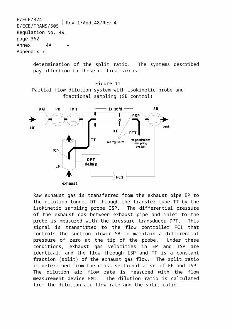
E/ECE/324E/ECE/TRANS/505 Rev.1/Add.48/Rev.4
Regulation No. 49page 362Annex 4B – Appendix 3
For the measurement of the sample concentrations.
A.3.1.4. Non-methane cutter method (NMC)
The cutter oxidizes all hydrocarbons except CH4 to CO2 and H2O, so that by passing the sample through the NMC only CH4 is detected by the HFID. In addition to the usual HC sampling train (see figures 9 and 10), a second HC sampling train shall be installed equipped with a cutter as laid out in figure 11. This allows simultaneous measurement of total HC and NMHC.
The cutter shall be characterized at or above 600 K (327°C) prior to test work with respect to its catalytic effect on CH4 and C2H6 at H2O values representative of exhaust stream conditions. The dew point and O2 level of the sampled exhaust stream must be known. The relative response of the FID to CH4 and C2H6 shall be determined in accordance with paragraph 9.3.8.
Figure 11Schematic flow diagram of methane analysis with the NMC
A.3.1.5. Components of figure 11
NMC Non-methane cutter
To oxidize all hydrocarbons except methane.
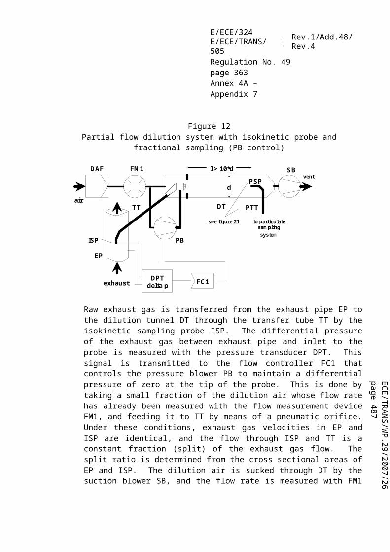
ECE/TR
AN
S/WP.29/2007/26
page 487
E/ECE/324E/ECE/TRANS/505 Rev.1/Add.48/Rev.4
Regulation No. 49page 363Annex 4B – Appendix 3
HC
Heated flame ionization detector (HFID) or flame ionization detector (FID) to measure the HC and CH4 concentrations. The temperature of the HFID shall be kept at 453 K to 473 K (180 °C to 200 °C).
V1 Selector valve
To select zero and span gas.
R Pressure regulator
To control the pressure in the sampling line and the flow to the HFID.
A.3.2. Dilution and particulate sampling system
A.3.2.1. Introduction
This annex contains the basic requirements and the general descriptions of the dilution and particulate sampling systems. Since various configurations can produce equivalent results, exact conformance with figures 12 to 17 is not required. However, conformance with the basic requirements such as sampling line dimensions, heating and design is mandatory. Additional components such as instruments, valves, solenoids, pumps, and switches may be used to provide additional information and coordinate the functions of the component systems. Other components which are not needed to maintain the accuracy on some systems, may be excluded if their exclusion is based upon good engineering judgment.
A.3.2.2. Description of partial flow system
A dilution system is described based upon the dilution of a part of the exhaust stream. Splitting of the exhaust stream and the following dilution process may be done by different dilution system types. For subsequent collection of the particulates, the entire dilute exhaust gas or only a portion of the dilute exhaust gas is passed to the particulate sampling system. The first method is referred to as total sampling type, the second method as fractional sampling type. The calculation of the dilution ratio depends upon the type of system used.
With the total sampling system as shown in figure 12, raw exhaust gas is transferred from the exhaust pipe (EP) to the dilution tunnel (DT) through the sampling probe (SP) and the transfer tube (TT). The total flow through the tunnel is adjusted with the flow controller FC2 and the sampling pump (P) of the particulate sampling system (see figure 16). The dilution airflow is controlled by the flow controller FC1, which may use qmew or qmaw and qmf as command signals, for the desired exhaust split.
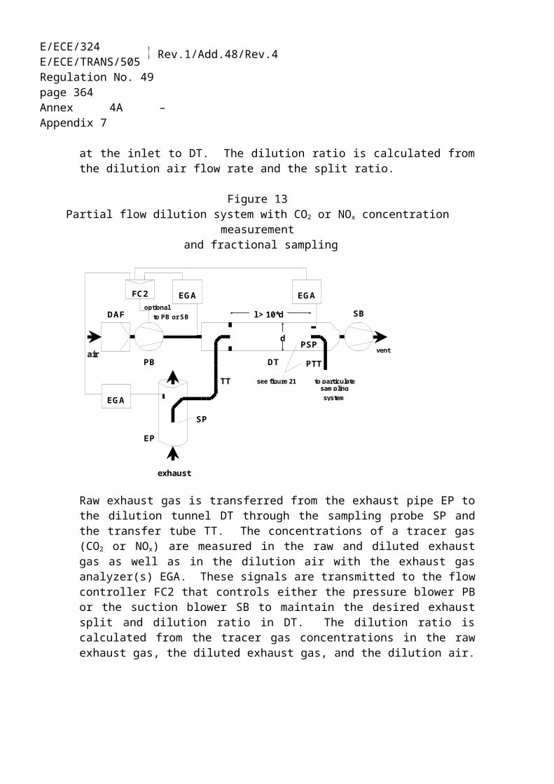
E/ECE/324E/ECE/TRANS/505 Rev.1/Add.48/Rev.4
Regulation No. 49page 364Annex 4B – Appendix 3
The sample flow into DT is the difference of the total flow and the dilution airflow. The dilution airflow rate is measured with the flow measurement device FM1, the total flow rate with the flow measurement device FM3 of the particulate sampling system (see figure 16). The dilution ratio is calculated from these two flow rates.
a = exhaust b = optional c = details see Figure 16
Figure 12Scheme of partial flow dilution system (total sampling type)
With the fractional sampling system as shown in figure 13, raw exhaust gas is transferred from the exhaust pipe EP to the dilution tunnel DT through the sampling probe (SP) and the transfer tube (TT). The total flow through the tunnel is adjusted with the flow controller FC1 connected either to the dilution airflow or to the suction blower for the total tunnel flow. The flow controller FC1 may use qmew or qmaw and qmf as command signals for the desired exhaust split. The sample flow into DT is the difference of the total flow and the dilution airflow. The dilution airflow rate is measured with the flow measurement device FM1, the total flow rate with the flow measurement device FM2. The dilution ratio is calculated from these two flow rates. From DT, a particulate sample is taken with the particulate sampling system (see figure 16).

ECE/TR
AN
S/WP.29/2007/26
page 487
E/ECE/324E/ECE/TRANS/505 Rev.1/Add.48/Rev.4
Regulation No. 49page 365Annex 4B – Appendix 3
a = exhaust b = to PB or SB c = details see Figure 16 d = to particulate sampling system e = vent
Figure 13Scheme of partial flow dilution system (fractional sampling type)
A.3.2.3. Components of figures 12 and 13
EP Exhaust pipe
The exhaust pipe may be insulated. To reduce the thermal inertia of the exhaust pipe a thickness to diameter ratio of 0.015 or less is recommended. The use of flexible sections shall be limited to a length to diameter ratio of 12 or less. Bends shall be minimized to reduce inertial deposition. If the system includes a test bed silencer the silencer may also be insulated. It is recommended to have a straight pipe of 6 pipe diameters upstream and 3 pipe diameters downstream of the tip of the probe.
SP Sampling probe
The type of probe shall be either of the following(a) open tube facing upstream on the exhaust pipe centreline(b) open tube facing downstream on the exhaust pipe centreline(c) multiple hole probe as described under SP in paragraph A.3.1.3.(d) hatted probe facing upstream on the exhaust pipe centreline as shown in
figure 14
The minimum inside diameter of the probe tip shall be 4 mm. The minimum diameter ratio between exhaust pipe and probe shall be 4.

E/ECE/324E/ECE/TRANS/505 Rev.1/Add.48/Rev.4
Regulation No. 49page 366Annex 4B – Appendix 3
When using probe type (a), an inertial pre-classifier (cyclone or impactor) with at 50 per cent cut point between 2.5 and 10 µm shall be installed immediately upstream of the filter holder.
Figure 14Scheme of hatted probe
TT Exhaust transfer tube
The transfer tube shall be:(a) as short as possible, but not more than 1 m in length;(b) equal to or greater than the probe diameter, but not more than 25 mm in
diameter;(c) exiting on the centreline of the dilution tunnel and pointing downstream.
The tube shall be insulated with material with a maximum thermal conductivity of 0.05 W/mK with a radial insulation thickness corresponding to the diameter of the probe, or heated.
FC1 Flow controller
A flow controller shall be used to control the dilution airflow through the pressure blower PB and/or the suction blower SB. It may be connected to the exhaust flow sensor signals specified in paragraph 8.3.1. The flow controller may be installed upstream or downstream of the respective blower. When using a pressurized air supply, FC1 directly controls the airflow.
FM1 Flow measurement device
Gas meter or other flow instrumentation to measure the dilution airflow. FM1 is optional if the pressure blower PB is calibrated to measure the flow.
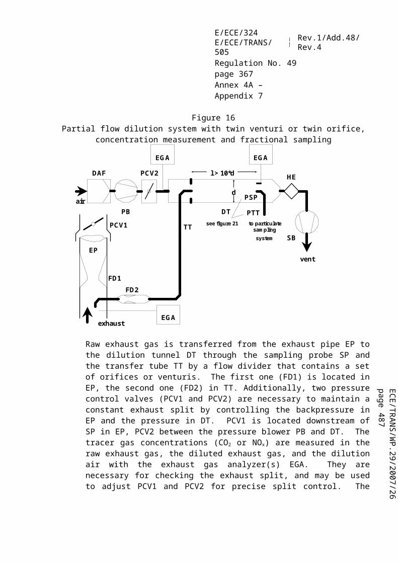
ECE/TR
AN
S/WP.29/2007/26
page 487
E/ECE/324E/ECE/TRANS/505 Rev.1/Add.48/Rev.4
Regulation No. 49page 367Annex 4B – Appendix 3
DAF Dilution air filter
The dilution air (ambient air, synthetic air, or nitrogen) shall be filtered with a high-efficiency (HEPA) filter that has an initial minimum collection efficiency of 99.97 per cent. The dilution air shall have a temperature of higher than 288 K (15 °C), and may be dehumidified.
FM2 Flow measurement device (fractional sampling type, figure 13 only)
Gas meter or other flow instrumentation to measure the diluted exhaust gas flow. FM2 is optional if the suction blower SB is calibrated to measure the flow.
PB Pressure blower (fractional sampling type, figure 13 only)
To control the dilution airflow rate, PB may be connected to the flow controllers FC1 or FC2. PB is not required when using a butterfly valve. PB may be used to measure the dilution airflow, if calibrated.
SB Suction blower (fractional sampling type, figure 13 only)
SB may be used to measure the diluted exhaust gas flow, if calibrated.
DT Dilution tunnel
The dilution tunnel:(a) shall be of a sufficient length to cause complete mixing of the exhaust and
dilution air under turbulent flow conditions for a fractional sampling system, i.e. complete mixing is not required for a total sampling system;
(b) shall be constructed of stainless steel;(c) shall be at least 75 mm in diameter for the fractional sampling type;(d) is recommended to be at least 25 mm in diameter for the total sampling type;(e) may be heated to no greater than 325 K (52 °C) wall temperature;(f) may be insulated.
PSP Particulate sampling probe (fractional sampling type, figure 13 only)
The particulate sampling probe is the leading section of the particulate transfer tube PTT (see paragraph A.3.2.5.) and(a) shall be installed facing upstream at a point where the dilution air and exhaust
gas are well mixed, i.e. on the dilution tunnel DT centreline approximately 10 tunnel diameters downstream of the point where the exhaust enters the dilution tunnel;
(b) shall be 12 mm in minimum inside diameter;

E/ECE/324E/ECE/TRANS/505 Rev.1/Add.48/Rev.4
Regulation No. 49page 368Annex 4B – Appendix 3
(c) may be heated to no greater than 325 K (52 °C) wall temperature by direct heating or by dilution air pre-heating, provided the dilution air temperature does not exceed 325 K (52 °C) prior to the introduction of the exhaust into the dilution tunnel;
(d) may be insulated.
A.3.2.4. Description of full flow dilution system
A dilution system is described based upon the dilution of the total amount of raw exhaust gas in the dilution tunnel DT using the CVS (constant volume sampling) concept, and is shown in figure 15.
The diluted exhaust gas flow rate shall be measured either with a positive displacement pump (PDP), with a critical flow venturi (CFV) or with a subsonic venturi (SSV). A heat exchanger (HE) or electronic flow compensation (EFC) may be used for proportional particulate sampling and for flow determination. Since particulate mass determination is based on the total diluted exhaust gas flow, it is not necessary to calculate the dilution ratio.
For subsequent collection of the particulates, a sample of the dilute exhaust gas shall be passed to the double dilution particulate sampling system (see figure 17). Although partly a dilution system, the double dilution system is described as a modification of a particulate sampling system, since it shares most of the parts with a typical particulate sampling system.
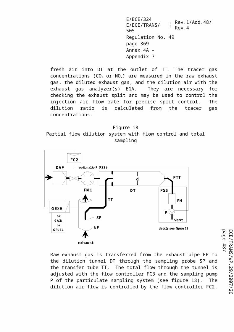
ECE/TR
AN
S/WP.29/2007/26
page 487
E/ECE/324E/ECE/TRANS/505 Rev.1/Add.48/Rev.4
Regulation No. 49page 369Annex 4B – Appendix 3
a = analyzer system b = background air c = exhaust d = details see Figure 17 e = to double dilution system f = if EFC is used i = vent g = optional h = or
Figure 15Scheme of full flow dilution system (CVS)
A.3.2.5. Components of figure 15
EP Exhaust pipe
The exhaust pipe length from the exit of the engine exhaust manifold, turbocharger outlet or after-treatment device to the dilution tunnel shall be not more than 10 m. If the system exceeds 4 m in length, then all tubing in excess of 4 m shall be insulated, except for an in-line smoke meter, if used. The radial thickness of the insulation shall be at least 25 mm. The thermal conductivity of the insulating material shall have a value no greater than 0.1 W/mK measured at 673 K. To reduce the thermal inertia of the exhaust pipe a thickness-to-diameter ratio of 0.015 or less is recommended. The use of flexible sections shall be limited to a length-to-diameter ratio of 12 or less.
PDP Positive displacement pump
The PDP meters total diluted exhaust flow from the number of the pump revolutions and the pump displacement. The exhaust system backpressure shall not be artificially lowered by the PDP or dilution air inlet system. Static exhaust backpressure measured with the PDP system operating shall remain within 1.5 kPa
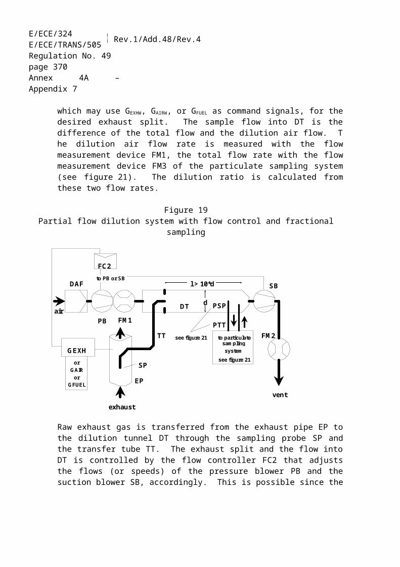
E/ECE/324E/ECE/TRANS/505 Rev.1/Add.48/Rev.4
Regulation No. 49page 370Annex 4B – Appendix 3
of the static pressure measured without connection to the PDP at identical engine speed and load. The gas mixture temperature immediately ahead of the PDP shall be within 6 K of the average operating temperature observed during the test, when no flow compensation (EFC) is used. Flow compensation is only permitted, if the temperature at the inlet to the PDP does not exceed 323 K (50 °C).
CFV Critical flow venturi
CFV measures total diluted exhaust flow by maintaining the flow at chocked conditions (critical flow). Static exhaust backpressure measured with the CFV system operating shall remain within 1.5 kPa of the static pressure measured without connection to the CFV at identical engine speed and load. The gas mixture temperature immediately ahead of the CFV shall be within 11 K of the average operating temperature observed during the test, when no flow compensation (EFC) is used.
SSV Subsonic venturi
SSV measures total diluted exhaust flow by using the gas flow function of a subsonic venturi in dependence of inlet pressure and temperature and pressure drop between venturi inlet and throat. Static exhaust backpressure measured with the SSV system operating shall remain within 1.5 kPa of the static pressure measured without connection to the SSV at identical engine speed and load. The gas mixture temperature immediately ahead of the SSV shall be within 11 K of the average operating temperature observed during the test, when no flow compensation (EFC) is used.
HE Heat exchanger (optional)
The heat exchanger shall be of sufficient capacity to maintain the temperature within the limits required above. If EFC is used, the heat exchanger is not required.
EFC Electronic flow compensation (optional)
If the temperature at the inlet to the PDP, CFV or SSV is not kept within the limits stated above, a flow compensation system is required for continuous measurement of the flow rate and control of the proportional sampling into the double dilution system. For that purpose, the continuously measured flow rate signals are used to maintain the proportionality of the sample flow rate through the particulate filters of the double dilution system (see figure 17) within 2.5 per cent.

ECE/TR
AN
S/WP.29/2007/26
page 487
E/ECE/324E/ECE/TRANS/505 Rev.1/Add.48/Rev.4
Regulation No. 49page 371Annex 4B – Appendix 3
DT Dilution tunnel
The dilution tunnel(a) shall be small enough in diameter to cause turbulent flow (Reynolds Number
greater than 4,000) and of sufficient length to cause complete mixing of the exhaust and dilution air;
(b) shall be at least 75 mm in diameter;(c) may be insulated.
The engine exhaust shall be directed downstream at the point where it is introduced into the dilution tunnel, and thoroughly mixed. A mixing orifice may be used.
For the double dilution system, a sample from the dilution tunnel is transferred to the secondary dilution tunnel where it is further diluted, and then passed through the sampling filters (figure 17). The flow capacity of the PDP or CFV must be sufficient to maintain the diluted exhaust stream in the DT at a temperature of less than or equal to 464 K (191 °C) at the sampling zone. The secondary dilution system shall provide sufficient secondary dilution air to maintain the doubly diluted exhaust stream at a temperature between 315 K (42 °C) and 325 K (52 °C) immediately before the particulate filter.
DAF Dilution air filter
The dilution air (ambient air, synthetic air, or nitrogen) shall be filtered with a high-efficiency (HEPA) filter that has an initial minimum collection efficiency of 99.97 per cent. The dilution air shall have a temperature of > 288 K (15 °C), and may be dehumidified.
PSP Particulate sampling probe
The probe is the leading section of PTT and(a) shall be installed facing upstream at a point where the dilution air and exhaust
gases are well mixed, i.e. on the dilution tunnel DT centreline of the dilution systems, approximately 10 tunnel diameters downstream of the point where the exhaust enters the dilution tunnel;
(b) shall be of 12 mm minimum inside diameter;(c) may be heated to no greater than 325 K (52 °C) wall temperature by direct
heating or by dilution air pre-heating, provided the air temperature does not exceed 325 K (52 °C) prior to the introduction of the exhaust in the dilution tunnel;
(d) may be insulated.

E/ECE/324E/ECE/TRANS/505 Rev.1/Add.48/Rev.4
Regulation No. 49page 372Annex 4B – Appendix 3
A.3.2.6. Description of particulate sampling system
The particulate sampling system is required for collecting the particulates on the particulate filter and is shown in figures 16 and 17. In the case of total sampling partial flow dilution, which consists of passing the entire diluted exhaust sample through the filters, the dilution and sampling systems usually form an integral unit (see figure 12). In the case of fractional sampling partial flow dilution or full flow dilution, which consists of passing through the filters only a portion of the diluted exhaust, the dilution and sampling systems usually form different units.
For a partial flow dilution system, a sample of the diluted exhaust gas is taken from the dilution tunnel DT through the particulate sampling probe PSP and the particulate transfer tube PTT by means of the sampling pump P, as shown in figure 16. The sample is passed through the filter holder(s) FH that contain the particulate sampling filters. The sample flow rate is controlled by the flow controller FC3.
For of full flow dilution system, a double dilution particulate sampling system shall be used, as shown in figure 17. A sample of the diluted exhaust gas is transferred from the dilution tunnel DT through the particulate sampling probe PSP and the particulate transfer tube PTT to the secondary dilution tunnel SDT, where it is diluted once more. The sample is then passed through the filter holder(s) FH that contain the particulate sampling filters. The dilution airflow rate is usually constant whereas the sample flow rate is controlled by the flow controller FC3. If electronic flow compensation EFC (see figure 15) is used, the total diluted exhaust gas flow is used as command signal for FC3.
a = from dilution tunnel
Figure 16Scheme of particulate sampling system
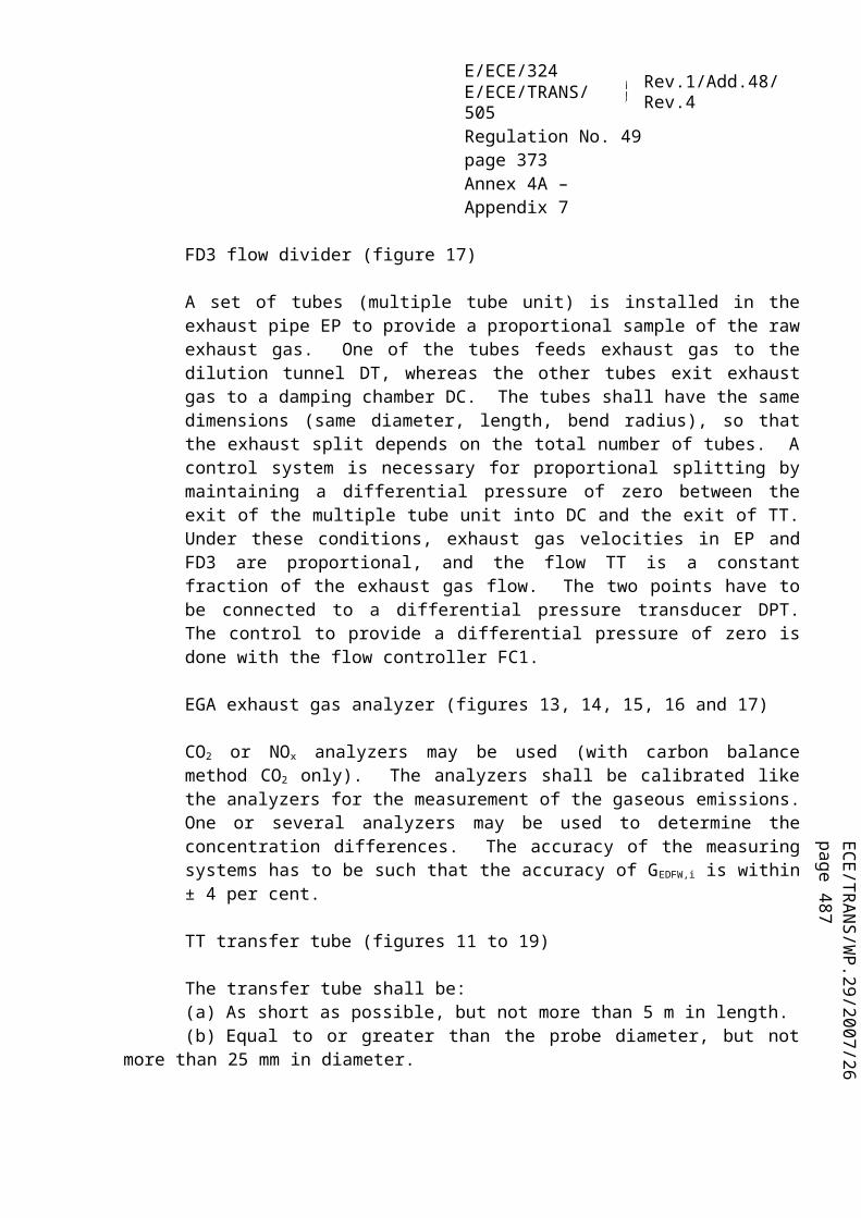
ECE/TR
AN
S/WP.29/2007/26
page 487
E/ECE/324E/ECE/TRANS/505 Rev.1/Add.48/Rev.4
Regulation No. 49page 373Annex 4B – Appendix 3
a = diluted exhaust from DT b = optional c = vent d = secondary dilution air
Figure 17Scheme of double dilution particulate sampling system
A.3.2.7. Components of figures 16 (partial flow system only) and 17 (full flow system only)
PTT Particulate transfer tube
The particulate transfer tube shall not exceed 1,020 mm in length, and shall be minimized in length whenever possible.
The dimensions are valid for:(a) the partial flow dilution fractional sampling system from the probe tip to the
filter holder;(b) the partial flow dilution total sampling system from the end of the dilution
tunnel to the filter holder;(c) the full flow double dilution system from the probe tip to the entrance of the
secondary dilution tunnel.
The transfer tube:
(a) may be heated to no greater than 325 K (52°C) wall temperature;(b) may be insulated.
SDT Secondary dilution tunnel (figure 17 only)
The secondary dilution tunnel should have a minimum diameter of 75 mm, and should be of sufficient length so as to provide a residence time of at least 0.25 s for the doubly diluted sample. The filter holder FH shall be located within 300 mm of the exit of the SDT.
The secondary dilution tunnel(a) may be heated to no greater than 325 K (52 °C) wall temperature by direct
heating or by dilution air pre heating, provided the air temperature does not exceed 325 K (52 °C) prior to the introduction of the exhaust into the dilution tunnel;
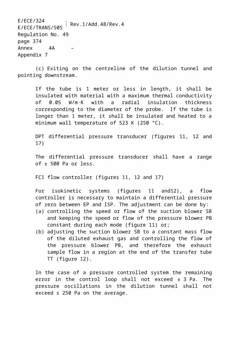
E/ECE/324E/ECE/TRANS/505 Rev.1/Add.48/Rev.4
Regulation No. 49page 374Annex 4B – Appendix 3
(b) may be insulated.
FH Filter holder
The filter holder:(a) may be heated to no greater than 325 K (52 °C) wall temperature;(b) may be insulated.
An inertial pre-classifier with a 50 per cent cut point between 2.5 µm and 10 µm shall be installed immediately upstream of the filter holder, if an open tube sampling probe facing upstream is used.
P Sampling pump
FC2 Flow controller
A flow controller shall be used for controlling the particulate sample flow rate.
FM3 Flow measurement device
Gas meter or flow instrumentation to determine the particulate sample flow through the particulate filter. It may be installed upstream or downstream of the sampling pump P.
FM4 Flow measurement device
Gas meter or flow instrumentation to determine the secondary dilution airflow through the particulate filter.
BV Ball valve (optional)
The ball valve shall have an inside diameter not less than the inside diameter of the particulate transfer tube PTT, and a switching time of less than 0.5 s.

ECE/TR
AN
S/WP.29/2007/26
page 487
E/ECE/324E/ECE/TRANS/505 Rev.1/Add.48/Rev.4
Regulation No. 49page 375Annex 4B – Appendix 4
Annex 4B - Appendix 4
DETERMINATION OF SYSTEM EQUIVALENCE
The determination of system equivalency according to paragraph 5.1.1. shall be based on a 7 sample pair (or larger) correlation study between the candidate system and one of the accepted reference systems of this annex using the appropriate test cycle(s). The equivalency criteria to be applied shall be the F-test and the two-sided Student t-test.
This statistical method examines the hypothesis that the sample standard deviation and sample mean value for an emission measured with the candidate system do not differ from the sample standard deviation and sample mean value for that emission measured with the reference system. The hypothesis shall be tested on the basis of a 10 per cent significance level of the F and t values. The critical F and t values for 7 to 10 sample pairs are given in table 8. If the F and t values calculated according to the equation below are greater than the critical F and t values, the candidate system is not equivalent.
The following procedure shall be followed. The subscripts R and C refer to the reference and candidate system, respectively:
(a) Conduct at least 7 tests with the candidate and reference systems operated in parallel. The number of tests is referred to as nR and nC.
(b) Calculate the mean values and and the standard deviations sR and sC.(c) Calculate the F value, as follows:
(82)
(the greater of the two standard deviations sR or sC must be in the numerator).
(d) Calculate the t value, as follows:
(83)
(e) Compare the calculated F and t values with the critical F and t values corresponding to the respective number of tests indicated in table 8. If larger sample sizes are selected, consult statistical tables for 10 per cent significance (90 per cent confidence) level.
(f) Determine the degrees of freedom (df), as follows:for the F-test: df = nR –1 / nC –1 (84)for the t-test: df = nC + nR –2 (85)

E/ECE/324E/ECE/TRANS/505 Rev.1/Add.48/Rev.4
Regulation No. 49page 376Annex 4B – Appendix 4
(g) Determine the equivalency, as follows:(i) if F < Fcrit and t < tcrit, then the candidate system is equivalent to the
reference system of this annex;(ii) if F Fcrit or t tcrit , then the candidate system is different from the
reference system of this annex.
Sample Size F-test t-testDf Fcrit df tcrit
7 6/6 3.055 12 1.7828 7/7 2.785 14 1.7619 8/8 2.589 16 1.74610 9/9 2.440 18 1.734
Table 8t and F values for selected sample sizes

ECE/TR
AN
S/WP.29/2007/26
page 487
E/ECE/324E/ECE/TRANS/505 Rev.1/Add.48/Rev.4
Regulation No. 49page 377Annex 4B – Appendix 5
Annex 4B - Appendix 5
CARBON FLOW CHECK
A.5.1. Introduction
All but a tiny part of the carbon in the exhaust comes from the fuel, and all but a minimal part of this is manifest in the exhaust gas as CO2. This is the basis for a system verification check based on CO2 measurements.
The flow of carbon into the exhaust measurement systems is determined from the fuel flow rate. The flow of carbon at various sampling points in the emissions and particulate sampling systems is determined from the CO2 concentrations and gas flow rates at those points.
In this sense, the engine provides a known source of carbon flow, and observing the same carbon flow in the exhaust pipe and at the outlet of the partial flow PM sampling system verifies leak integrity and flow measurement accuracy. This check has the advantage that the components are operating under actual engine test conditions of temperature and flow.
Figure 18 shows the sampling points at which the carbon flows shall be checked. The specific equations for the carbon flows at each of the sample points are given below.
Figure 18 Measuring points for carbon flow check
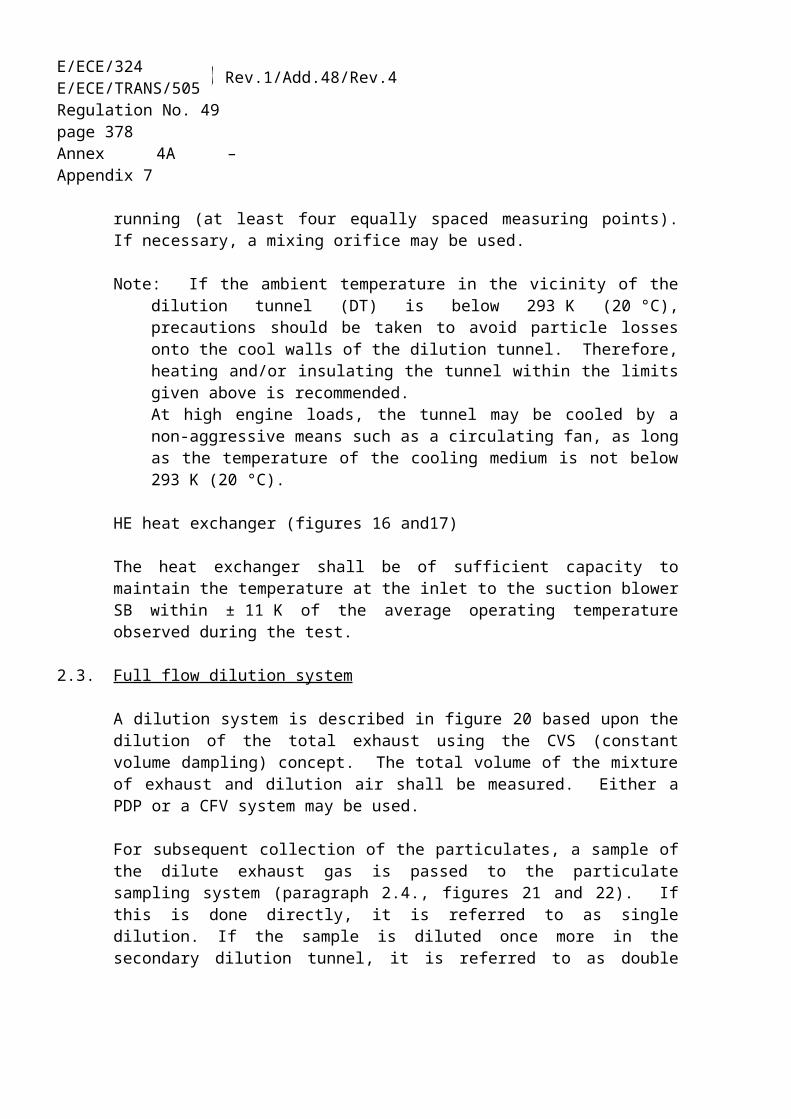
E/ECE/324E/ECE/TRANS/505 Rev.1/Add.48/Rev.4
Regulation No. 49page 378Annex 4B – Appendix 5
A.5.2. Carbon flow rate into the engine (location 1)
The carbon mass flow rate into the engine for a fuel CHO is given by:
(86)
where:qmf is the fuel mass flow rate, kg/s
A.5.3. Carbon flow rate in the raw exhaust (location 2)
The carbon mass flow rate in the exhaust pipe of the engine shall be determined from the raw CO2 concentration and the exhaust gas mass flow rate:
(87)
where:cCO2,r is the wet CO2 concentration in the raw exhaust gas, per centcCO2,a is the wet CO2 concentration in the ambient air, per centqmew is the exhaust gas mass flow rate on wet basis, kg/sMe is the molar mass of exhaust gas, g/mol
If CO2 is measured on a dry basis it shall be converted to a wet basis according to paragraph 8.1.
A.5.4. Carbon flow rate in the dilution system (location 3)
For the partial flow dilution system, the splitting ratio also needs to be taken into account. The carbon flow rate shall be determined from the dilute CO2
concentration, the exhaust gas mass flow rate and the sample flow rate:
(88)
where:cCO2,d is the wet CO2 concentration in the dilute exhaust gas at the outlet of the
dilution tunnel, per centcCO2,a is the wet CO2 concentration in the ambient air, per cent

ECE/TR
AN
S/WP.29/2007/26
page 487
E/ECE/324E/ECE/TRANS/505 Rev.1/Add.48/Rev.4
Regulation No. 49page 379Annex 4B – Appendix 5
qmew is the exhaust gas mass flow rate on wet basis, kg/sqmp is the sample flow of exhaust gas into partial flow dilution system, kg/sMe is the molar mass of exhaust gas, g/mol
If CO2 is measured on a dry basis, it shall be converted to wet basis according to paragraph 8.1.
A.5.5. Calculation of the molar mass of the exhaust gas
The molar mass of the exhaust gas shall be calculated according to equation 28 (see paragraph 8.3.2.5.)
Alternatively, the following exhaust gas molar masses may be used:
Me (diesel) = 28.9 g/molMe (LPG) = 28.6 g/molMe (NG) = 28.3 g/mol

E/ECE/324E/ECE/TRANS/505 Rev.1/Add.48/Rev.4
Regulation No. 49page 380Annex 4B – Appendix 6
Annex 4B - Appendix 6
EXAMPLE OF CALCULATION PROCEDURE
A.6.1. Basic data for stoichiometric calculations
Atomic mass of hydrogen 1.00794 g/atomAtomic mass of carbon 12.011 g/atomAtomic mass of sulphur 32.065 g/atomAtomic mass of nitrogen 14.0067 g/atomAtomic mass of oxygen 15.9994 g/atomAtomic mass of argon 39.9 g/atomMolar mass of water 18.01534 g/molMolar mass of carbon dioxide 44.01 g/molMolar mass of carbon monoxide 28.011 g/molMolar mass of oxygen 31.9988 g/molMolar mass of nitrogen 28.011 g/molMolar mass of nitric oxide 30.008 g/molMolar mass of nitrogen dioxide 46.01 g/molMolar mass of sulphur dioxide 64.066 g/molMolar mass of dry air 28.965 g/mol
Assuming no compressibility effects, all gases involved in the engine intake/combustion/exhaust process can be considered to be ideal and any volumetric calculations shall therefore be based on a molar volume of 22.414 l/mol according to Avogadro's hypothesis.
A.6.2. Gaseous emissions (diesel fuel)
The measurement data of an individual point of the test cycle (data sampling rate of 1 Hz) for the calculation of the instantaneous mass emission are shown below. In this example, CO and NOx are measured on a dry basis, HC on a wet basis. The HC concentration is given in propane equivalent (C3) and has to be multiplied by 3 to result in the C1 equivalent. The calculation procedure is identical for the other points of the cycle.
The calculation example shows the rounded intermediate results of the different steps for better illustration. It should be noted that for actual calculation, rounding of intermediate results is not permitted (see paragraph 8).
Ta,i
(K)Ha,i
(g/kg)Wact
kWhqmew,i
(kg/s)qmaw,i
(kg/s)qmf,i
(kg/s)cHC,i
(ppm)cCO,i
(ppm)cNOx,i
(ppm)295 8.0 40 0.155 0.150 0.005 10 40 500

ECE/TR
AN
S/WP.29/2007/26
page 487
E/ECE/324E/ECE/TRANS/505 Rev.1/Add.48/Rev.4
Regulation No. 49page 381Annex 4B – Appendix 6
The following fuel composition is considered:
Component Molar ratio per cent massH = 1.8529 wALF = 13.45C = 1.0000 wBET = 86.50S = 0.0002 wGAM = 0.050N = 0.0000 wDEL = 0.000O = 0.0000 wEPS = 0.000
Step 1: Dry/wet correction (paragraph 8.1.):
Equation (11):kf = 0.055584 x 13.45 - 0.0001083 x 86.5 - 0.0001562 x 0.05 = 0.7382
Equation (8): kw,a= =
0.9331
Equation (7): cCO,i (wet) = 40 x 0.9331 = 37.3 ppmcNOx,i (wet) = 500 x 0.9331 = 466.6 ppm
Step 2: NOx correction for temperature and humidity (paragraph 8.2.1.):
Equation (18): = 0.9576
Step 3: Calculation of the instantaneous emission of each individual point of the cycle (paragraph 8.3.2.4.):
Equation (25): mHC,i = 10 x 3 x 0.155 = 4.650mCO,i = 37.3 x 0.155 = 5.782mNox,I = 466.6 x 0.9576 x 0.155 = 69.26
Step 4: Calculation of the mass emission over the cycle by integration of the instantaneous emission values and the u values from table 4 (paragraph 8.3.2.4.):
The following calculation is assumed for the WHTC cycle (1,800 s) and the same emission in each point of the cycle.

E/ECE/324E/ECE/TRANS/505 Rev.1/Add.48/Rev.4
Regulation No. 49page 382Annex 4B – Appendix 6
Equation (25): mHC = 0.000479 x = 4.01 g/test
mCO = 0.000966 x = 10.05 g/test
mNOx = 0.001586 x = 197.72 g/test
Step 5: Calculation of the specific emissions (paragraph 8.5.2.1.):
Equation (56): eHC = 4.01 / 40 = 0.10 g/kWheCO = 10.05 / 40 = 0.25 g/kWheNOx = 197.72 / 40 = 4.94 g/kWh
A.6.2. Particulate Emission (Diesel Fuel)
pb
kPaWact
kWhqmew,i
(kg/s)qmf,i
(kg/s)qmdw,i
(kg/s)qmdew,i
(kg/s)muncor
(mg)msep
(kg)99 40 0.155 0.005 0.0015 0.0020 1.7000 1.515
Step 1: Calculation of medf (paragraph 8.3.3.5.2.):
Equation (37): rd,i = = 4
Equation (36): qmedf,i = 0.155 x 4 = 0.620 kg/s
Equation (35): medf = = 1,116 kg/test
Step 2: Buoyancy correction of the particulate mass (paragraph 9.4.3.5.)
Equation (72): ρa = = 1.164 kg/m3
Equation (71): mf = = 1.7006 mg
Step 3: Calculation of the particulate mass emission (paragraph 8.3.3.5.2.):
Equation (34): mPM = = 1.253 g/test

ECE/TR
AN
S/WP.29/2007/26
page 487
E/ECE/324E/ECE/TRANS/505 Rev.1/Add.48/Rev.4
Regulation No. 49page 383Annex 4B – Appendix 6
Step 4: Calculation of the specific emission (paragraph 8.5.2.1.):
Equation (56): ePM = 1.253 / 40 = 0.031 g/kWh
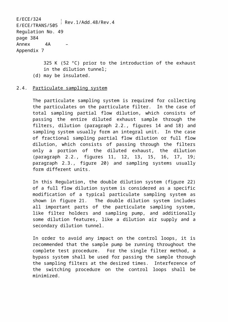
E/ECE/324E/ECE/TRANS/505 Rev.1/Add.48/Rev.4
Regulation No. 49page 384Annex 5
Annex 5
TECHNICAL CHARACTERISTICS OF REFERENCE FUEL PRESCRIBED FOR APPROVAL TESTS AND TO VERIFY THE CONFORMITY OF PRODUCTION
1.1. DIESEL REFERENCE FUEL FOR TESTING ENGINES TO THE EMISSION LIMITS GIVEN IN ROW A OF THE TABLES IN PARAGRAPH 5.2.1. OF THIS REGULATION (a)
Parameter Unit Limits (b) Test Method PublicationMinimum Maximum
Cetane number (c) 52 54 EN-ISO 5165 1998 (d)
Density at 15 °C kg/m3 833 837 EN-ISO 3675 1995Distillation:— 50 per cent point °C 245 — EN-ISO 3405 1998— 95 per cent point °C 345 350 EN-ISO 3405 1998— final boiling point °C — 370 EN-ISO 3405 1998Flash point °C 55 — EN 27719 1993CFPP °C — − 5 EN 116 1981Viscosity at 40 °C mm2/s 2.5 3.5 EN-ISO 3104 1996Polycyclic aromatic hydrocarbons
per cent m/m
3.0 6.0 IP 391 (*) 1995
Sulphur content (e) mg/kg — 300 pr. EN-ISO/DIS 14596
1998 (d)
Copper corrosion — 1 EN-ISO 2160 1995Conradson carbon residue (10 per cent DR)
per cent m/m
— 0.2 EN-ISO 10370
Ash content per cent m/m
— 0.01 EN-ISO 6245 1995
Water content per cent m/m
— 0.05 EN-ISO 12937 1995
Neutralisation (strong acid) number
mg KOH/g
— 0.02 ASTM D 974-95 1998 (d)
Oxidation stability (f) mg/ml — 0.025 EN-ISO 12205 1996(*) New and better method for polycyclic aromatics under development
per cent m/m
— — EN 12916 [1997] (d)
(a) If it is required to calculate the thermal efficiency of an engine or vehicle, the calorific value of the fuel can be calculated from:Specific energy (calorific value)(net) in MJ/kg = (46.423 - 8.792d2 + 3.170d)(1 - (x + y + s)) + 9.420s - 2.499xwhere.d = the density at 15 °Cx = the proportion by mass of water ( per cent divided by 100)y = the proportion by mass of ash ( per cent divided by 100)s = the proportion by mass of sulphur ( per cent divided by 100).
(b) The values quoted in the specification are "true values". In establishment of their limit values

ECE/TR
AN
S/WP.29/2007/26
page 487
E/ECE/324E/ECE/TRANS/505 Rev.1/Add.48/Rev.4
Regulation No. 49page 385Annex 5
the terms of ISO 4259, Petroleum products - Determination and application of precision data in relation to methods of test, have been applied and in fixing a minimum value, a minimum difference of 2R above zero has been taken into account; in fixing a maximum and minimum value, the minimum difference is 4R (R = reproducibility). Notwithstanding this measure, which is necessary for statistical reasons, the manufacturer of a fuel should nevertheless aim at a zero value where the stipulated maximum value is 2R and at the mean value in the case of quotations of maximum and minimum limits. Should it be necessary to clarify the question as to whether a fuel meets the requirements of the specification, the terms of ISO 4259 should be applied.
(c) The range for cetane number is not in accordance with the requirement of a minimum range of 4R. However, in the case of dispute between fuel supplier and fuel user. the terms in ISO 4259 can be used to resolve such disputes provided replicate measurements, of sufficient number to achieve the necessary precision, are made in preference to single determinations.
(d) The month of publication will be completed in due course.(e) The actual sulphur content of the fuel used for the test shall be reported.(f) Even though oxidation stability is controlled, it is likely that shelf life will be limited. Advice
should be sought from the supplier as to storage conditions and life.

E/ECE/324E/ECE/TRANS/505 Rev.1/Add.48/Rev.4
Regulation No. 49page 386Annex 5
1.2. DIESEL REFERENCE FUEL FOR TESTING ENGINES TO THE EMISSION LIMITS GIVEN IN ROWS B1, B2 OR C OF THE TABLES IN PARAGRAPH 5.2.1. OF THIS REGULATION
Parameter Unit Limits (a)
Test Methodminimum maximumCetane number (b) 52.0 54.0 EN-ISO 5165Density at 15°C kg/m3 833 837 EN-ISO 3675Distillation: 50 per cent point °C 245 - EN-ISO 3405 95 per cent point °C 345 350 EN-ISO 3405- Final boiling point °C - 370 EN-ISO 3405Flash point °C 55 - EN 22719CFPP °C - -5 EN 116Viscosity at 40°C mm2/s 2.3 3.3 EN-ISO 3104
Polycyclic aromatic hydrocarbons per cent m/m 2.0 6.0 IP 391
Sulphur content (c) mg/kg - 10 ASTM D 5453Copper corrosion - class 1 EN-ISO 2160Conradson carbon residue (10 per cent DR)
per cent m/m - 0.2 EN-ISO 10370
Ash content per cent m/m
- 0.01 EN-ISO 6245
Water content per cent m/m
- 0.02 EN-ISO 12937
Neutralisation (strong acid) number Mg KOH/g - 0.02 ASTM D 974
Oxidation stability (d) mg/ml - 0.025 EN-ISO 12205Lubricity (HFRR wear scan diameter at 60°C)
µm - 400 CEC F-06-A-96
FAME prohibited(a) The values quoted in the specifications are "true values". In establishment of their limit values the
terms of ISO 4259 "Petroleum products – Determination and application of precision data in relation to methods of test" have been applied and in fixing a minimum value, a minimum difference of 2R above zero has been taken into account; in fixing a maximum and minimum value, the minimum difference is 4R (R = reproducibility).Notwithstanding this measure, which is necessary for technical reasons, the manufacturer of fuels should nevertheless aim at a zero value where the stipulated maximum value is 2R and at the mean value in the case of quotations of maximum and minimum limits. Should it be necessary to clarify the questions as to whether a fuel meets the requirements of the specifications, the terms of ISO 4259 should be applied.
(b) The range for cetane number is not in accordance with the requirements of a minimum range of 4R. However, in the case of a dispute between fuel supplier and fuel user, the terms of ISO 4259 may be used to resolve such disputes provided replicate measurements, of sufficient number to archive the necessary precision, are made in preference to single determinations.
(c) The actual sulphur content of the fuel used for the Type I test shall be reported.(d) Even though oxidation stability is controlled, it is likely that shelf life will be limited. Advice should
be sought from the supplier as to storage conditions and life.
ECE/TR
AN
S/WP.29/2007/26
page 487
E/ECE/324E/ECE/TRANS/505 Rev.1/Add.48/Rev.4
Regulation No. 49page 387Annex 5
1.3. ETHANOL FOR DIESEL ENGINES (a)
Parameter Unit Limits (b) Test method (c)
Minimum MaximumAlcohol, mass per cent m/m 92.4 — ASTM D 5501Other alcohol than ethanol contained in total alcohol, mass
per cent m/m — 2 ASTM D 5501
Density at 15 °C kg/m3 795 815 ASTM D 4052Ash content per cent m/m 0.001 ISO 6245Flash point °C 10 ISO 2719Acidity, calculated as acetic acid per cent m/m — 0.0025 ISO 1388-2Neutralisation (strong acid) number
KOH mg/1 — 1
Colour According to scale
— 10 ASTM D 1209
Dry residue at 100 °C mg/kg 15 ISO 759Water content per cent m/m 6.5 ISO 760Aldehydes calculated as acetic acid
per cent m/m 0.0025 ISO 1388-4
Sulphur content mg/kg — 10 ASTM D 5453Esters, calculated as ethylacetate per cent m/m — 0.1 ASTM D 1617(a) Cetane improver, as specified by the engine manufacturer, may be added to the ethanol fuel.
The maximum allowed amount is 10 per cent m/m.(b) The values quoted in the specification are "true values". In establishment of their limit values
the terms of ISO 4259, Petroleum products - Determination and application of precision data in relation to methods of test, have been applied and in fixing a minimum value, a minimum difference of 2R above zero has been taken into account; in fixing a maximum and minimum value, the minimum difference is 4R (R - reproducibility). Notwithstanding this measure, which is necessary for statistical reasons, the manufacturer of a fuel should nevertheless aim at a zero value where the stipulated maximum value is 2R and at the mean value in the case of quotations of maximum and minimum limits. Should it be necessary to clarify the question as to whether a fuel meets the requirements of the specification, the terms of ISO 4259 should be applied.
(c) Equivalent ISO methods will be adopted when issued for all properties listed above

E/ECE/324E/ECE/TRANS/505 Rev.1/Add.48/Rev.4
Regulation No. 49page 388Annex 5
2. NATURAL GAS (NG)
European market fuels are available in two ranges:(a) the H range, whose extreme reference fuels are GR and G23;(b) the L range, whose extreme reference fuels are G23 and G25.
The characteristics of GR, G23 and G25 reference fuels are summarized below:
Reference fuel GR
Characteristics Units BasisLimits Test
MethodMinimum Maximum
Composition:
Methane % mole 87 84 89
Ethane % mole 13 11 15
Balance (a) % mole - - 1 ISO 6974
Sulphur content mg/m3 (b) - - 10 ISO 6326-5(a) Inerts +C2+(b) Value to be determined at standard conditions (293.2 K (20 °C) and
101.3 kPa).
Reference fuel G23
Characteristics Units BasisLimits Test
MethodMinimum Maximum
Composition:
Methane % mole 92.5 91.5 93.5
Balance (a) % mole - - 1 ISO 6974N2 7.5 6.5 8.5
Sulphur content mg/m3 (b) - - 10 ISO 6326-5(a) Inerts (different from N2) +C2+ /C2+(b) Value to be determined at standard conditions (293.2 K (20 °C) and
101.3 kPa).
ECE/TR
AN
S/WP.29/2007/26
page 487
E/ECE/324E/ECE/TRANS/505 Rev.1/Add.48/Rev.4
Regulation No. 49page 389Annex 5
Reference fuel G25
Characteristics Units BasisLimits Test
MethodMinimum Maximum
Composition:
Methane % mole 86 84 88
Balance (a) % mole - - 1 ISO 6974N2 14 12 16
Sulphur content mg/m3 (b) - - 10 ISO 6326-5(a) Inerts (different from N2) +C2+ /C2+(b) Value to be determined at standard conditions (293.2 K (20 °C) and
101.3 kPa).
E/ECE/324E/ECE/TRANS/505 Rev.1/Add.48/Rev.4
Regulation No. 49page 390Annex 5
3. TECHNICAL DATA OF THE LPG REFERENCE FUELS
A. TECHNICAL DATA OF THE LPG REFERENCE FUELS USED FOR TESTING VEHICLES TO THE EMISSION LIMITS GIVEN IN ROW A OF THE TABLES IN PARAGRAPH 5.2.1. OF THIS REGULATION
Parameter Unit Fuel A Fuel B Test methodComposition: ISO 7941C3-content per cent vol 50 ± 2 85 ± 2C4-content per cent vol balance balance< C3 , >C4 per cent vol Max. 2 max. 2Olefins per cent vol max. 12 max. 14Evaporation residue mg/kg max. 50 max. 50 ISO 13757Water at 0C free free visual inspectionTotal sulphur content mg/kg max. 50 max. 50 EN 24260Hydrogen sulphide none none ISO 8819Copper strip corrosion rating Class 1 class 1 ISO 6251 (a)
Odour characteristic characteristicMotor octane number min. 92.5 min. 92.5 EN 589 Annex B(a) This method may not accurately determine the presence of corrosive materials if the sample contains
corrosion inhibitors or other chemicals which diminish the corrosivity of the sample to the copper strip. Therefore, the addition of such compounds for the sole purpose of biasing the test method is prohibited.
B. TECHNICAL DATA OF THE LPG REFERENCE FUELS USED FOR TESTING VEHICLES TO THE EMISSION LIMITS GIVEN IN ROW B1, B2 OR C OF THE TABLES IN PARAGRAPH 5.2.1. OF THIS REGULATION
Parameter Unit Fuel A Fuel B Test methodComposition: ISO 7941C3-content per cent vol 50 ± 2 85 ± 2C4-content per cent vol balance balance< C3 , >C4 per cent vol max. 2 max. 2Olefins per cent vol max. 12 max. 14Evaporation residue mg/kg max. 50 max. 50 ISO 13757Water at 0C free free Visual inspectionTotal sulphur content mg/kg max. 10 max. 10 EN 24260Hydrogen sulphide none none ISO 8819Copper strip corrosion Rating class 1 class 1 ISO 6251 (a)
Odour characteristic characteristic
Motor octane number min. 92.5 min. 92.5 EN 589 Annex B(a) This method may not accurately determine the presence of corrosive materials if the sample contains
corrosion inhibitors or other chemicals which diminish the corrosivity of the sample to the copper strip. Therefore, the addition of such compounds for the sole purpose of biasing the test method is prohibited.

ECE/TR
AN
S/WP.29/2007/26
page 487
E/ECE/324E/ECE/TRANS/505 Rev.1/Add.48/Rev.4
Regulation No. 49page 391Annex 6
Annex 6
EXAMPLE OF CALCULATION PROCEDURE
1. ESC TEST
1.1. Gaseous emissions
The measurement data for the calculation of the individual mode results are shown below. In this example, CO and NOx are measured on a dry basis, HC on a wet basis. The HC concentration is given in propane equivalent (C3) and has to be multiplied by 3 to result in the C1 equivalent. The calculation procedure is identical for the other modes.
P Ta Ha GEXH GAIRW GFUEL HC CO NOx
(kW) (K) (g/kg) (kg) (kg) (kg) (ppm) (ppm) (ppm)82.9 294.8 7.81 563.38 545.29 18.09 6.3 41.2 495
Calculation of the dry to wet correction factor KW,r (Annex 4A, Appendix 1, paragraph 5.2.):
and
Calculation of the wet concentrations:CO = 41.2 0.9239 = 38.1 ppmNOx = 495 0.9239 = 457 ppm
Calculation of the NOx humidity correction factor KH,D (Annex 4A, Appendix 1, paragraph 5.3.):A = 0.309 18.09/541.06 − 0.0266 = −0.0163
B = − 0.209 18.09/541.06 + 0.00954 = 0.0026

E/ECE/324E/ECE/TRANS/505 Rev.1/Add.48/Rev.4
Regulation No. 49page 392Annex 6
Calculation of the emission mass flow rates (Annex 4A, Appendix 1, paragraph 5.4.):NOx = 0.001587 457 0.9625 563.38 = 393.27 g/hCO = 0.000966 38.1 563.38 = 20.735 g/hHC = 0.000479 6.3 3 563.38 = 5.100 g/h
Calculation of the specific emissions (Annex 4A, Appendix 1, paragraph 5.5.):
The following example calculation is given for CO; the calculation procedure is identical for the other components.
The emission mass flow rates of the individual modes are multiplied by the respective weighting factors, as indicated in Annex 4A, Appendix 1, paragraph 2.7.1., and summed up to result in the mean emission mass flow rate over the cycle:
CO = (6.7 0.15) + (24.6 0.08) + (20.5 0.10) + (20.7 0.10) + (20.6 0.05) + (15.0 0.05) + (19.7 0.05) + (74.5 0.09) + (31.5 0.10) + (81.9 0.08)+ (34.8 0.05) + (30.8 0.05) + (27.3 0.05)
= 30.91 g/h
The engine power of the individual modes is multiplied by the respective weighting factors, as indicated in Annex 4A, Appendix 1, paragraph 2.7.1., and summed up to result in the mean cycle power:
P(n) = (0.1 0.15) + (96.8 0.08) + (55.2 0.10) + (82.9 0.10) + (46.8 0.05) + (70.1 0.05) + (23.0 0.05) + (114.3 0.09) + (27.0 0.10) + (122.0 0.08) + (28.6 0.05) + (87.4 0.05) + (57.9 0.05)
= 60.006 kW
Calculation of the specific NOx emission of the random point (Annex 4A, Appendix 1, paragraph 5.6.1.):Assume the following values have been determined on the random point:nZ 1,600 min−1
MZ 495 NmNOx mass,Z 487.9 g/h (calculated according to the previous formulae)P(n)Z 83 kWNOx,Z 487.9/83 = 5.878 g/kWh

ECE/TR
AN
S/WP.29/2007/26
page 487
E/ECE/324E/ECE/TRANS/505 Rev.1/Add.48/Rev.4
Regulation No. 49page 393Annex 6
Determination of the emission value from the test cycle (Annex 4A, Appendix 1, paragraph 5.6.2.):Assume the values of the four enveloping modes on the ESC to be as follows:
nRT nSU ER ES ET EU MR MS MT MU
1368 1785 5.943 5.565 5.889 4.973 515 460 681 610
ETU = 5.889 + (4.973 − 5.889) (1,600 − 1,368) / (1,785 − 1,368) = 5.377 g/kWhERS = 5.943 + (5.565 − 5.943) (1,600 − 1,368) / (1,785 − 1,368) = 5.732 g/kWhMTU = 681 + (601 − 681) (1,600 − 1,368) / (1,785 − 1,368) = 641.3 NmMRS = 515 + (460 − 515) (1,600 − 1,368) / (1,785 − 1,368) = 484.3 NmEZ = 5.732 + (5.377 − 5.732) (495 − 484.3) / (641.3 − 484.3) = 5.708 g/kWh
Comparison of the NOx emission values (Annex 4A, Appendix 1, paragraph 5.6.3.):NOx diff = 100 (5.878 − 5.708) / 5.708 = 2.98 per cent
1.2. Particulate emissions
Particulate measurement is based on the principle of sampling the particulates over the complete cycle, but determining the sample and flow rates (MSAM and GEDF) during the individual modes. The calculation of GEDF depends on the system used. In the following examples, a system with CO2 measurement and carbon balance method and a system with flow measurement are used. When using a full flow dilution system, GEDF
is directly measured by the CVS equipment.
Calculation of GEDF (Annex 4A, Appendix 1, paragraphs 6.2.3. and 6.2.4.):
Assume the following measurement data of mode 4. The calculation procedure is identical for the other modes.
GEXH GFUEL GDILW GTOTW CO2D CO2A
(kg/h) (kg/h) (kg/h) (kg/h) (per cent) (per cent)334.02 10.76 5.4435 6.0 0.657 0.040
(a) carbon balance method
(b) flow measurement method
GEDF W = 334.02 10.78 = 3,600.7 kg/h

E/ECE/324E/ECE/TRANS/505 Rev.1/Add.48/Rev.4
Regulation No. 49page 394Annex 6
Calculation of the mass flow rate (Annex 4A, Appendix 1, paragraph 6.4.):
The GEDFW flow rates of the individual modes are multiplied by the respective weighting factors, as indicated in Annex 4A, Appendix 1, paragraph 2.7.1., and summed up to result in the mean GEDF over the cycle. The total sample rate MSAM is summed up from the sample rates of the individual modes.
WEDFG = (3,567 0.15) + (3,592 0.08) + (3,611 0.10) + (3,600 0.10) + (3,618 0.05) + (3,600 0.05) + (3,640 0.05) + (3,614 0.09) + (3,620 0.10) + (3,601 0.08) + (3,639 0.05) + (3,582 0.05) + (3,635 0.05)
= 3,604.6 kg/h
MSAM = 0.226 + 0.122 + 0.151 + 0.152 + 0.076 + 0.076 + 0.076 + 0.136 + 0.151 + 0.121 + 0.076 + 0.076 + 0.075
= 1.515 kg
Assume the particulate mass on the filters to be 2.5 mg, then
Background correction (optional)
Assume one background measurement with the following values. The calculation of the dilution factor DF is identical to paragraph 3.1. of this annex and not shown here.
Md = 0.1 mg; MDIL = 1.5 kg
Sum of DF = [(1−1/119.15) 0.15] + [(1−1/8.89) 0.08] + [(1−1/14.75) 0.10] + [(1−1/10.10) 0.10] + [(1−1/18.02) 0.05] + [(1−1/12.33) 0.05] + [(1−1/32.18) 0.05] + [(1−1/6.94) 0.09] + [(1−1/25.19) 0.10] + [(1−1/6.12) 0.08] + [(1−1/20.87) 0.05] + [(1−1/8.77) 0.05] + [(1−1/12.59) 0.05]
= 0.923

ECE/TR
AN
S/WP.29/2007/26
page 487
E/ECE/324E/ECE/TRANS/505 Rev.1/Add.48/Rev.4
Regulation No. 49page 395Annex 6
Calculation of the specific emission (Annex 4A, Appendix 1, paragraph 6.5.):P(n) = (0.1 0.15) + (96.8 0.08) + (55.2 0.10) + (82.9 0.10) + (46.8 0.05 +
(70.1 0.05) + (23.0 0.05) + (114.3 0.09) + (27.0 0.10) + (122.0 0.08) + (28.6 0.05) + (87.4 0.05) + (57.9 0.05)
= 60.006 kW
if background corrected PT = (5.726/60.006) = 0.095 g/kWh,
Calculation of the specific weighting factor (Annex 4A, Appendix 1, paragraph 6.6.):
Assume the values calculated for mode 4 above, then Wfei = (0.152 3,604.6/1.515 3,600.7) = 0.1004
This value is within the required value of 0.10 ± 0.003.
2. ELR TEST
Since Bessel filtering is a completely new averaging procedure in European exhaust legislation, an explanation of the Bessel filter, an example of the design of a Bessel algorithm, and an example of the calculation of the final smoke value is given below. The constants of the Bessel algorithm only depend on the design of the opacimeter and the sampling rate of the data acquisition system. It is recommended that the opacimeter manufacturer provide the final Bessel filter constants for different sampling rates and that the customer use these constants for designing the Bessel algorithm and for calculating the smoke values.
2.1. General remarks on the Bessel filter
Due to high frequency distortions, the raw opacity signal usually shows a highly scattered trace. To remove these high frequency distortions a Bessel filter is required for the ELR-Test. The Bessel filter itself is a recursive, second-order low-pass filter which guarantees the fastest signal rise without overshoot.
Assuming a real time raw exhaust plume in the exhaust tube, each opacimeter shows a delayed and differently measured opacity trace. The delay and the magnitude of the measured opacity trace is primarily dependent on the geometry of the measuring chamber of the opacimeter, including the exhaust sample lines, and on the time needed for processing the signal in the electronics of the opacimeter. The values that

E/ECE/324E/ECE/TRANS/505 Rev.1/Add.48/Rev.4
Regulation No. 49page 396Annex 6
characterize these two effects are called the physical and the electrical response time which represent an individual filter for each type of opacimeter.
The goal of applying a Bessel filter is to guarantee a uniform overall filter characteristic of the whole opacimeter system, consisting of:(a) physical response time of the opacimeter (tp)(b) electrical response time of the opacimeter (te)(c) filter response time of the applied Bessel filter (tF)
The resulting overall response time of the system tAver is given by:2e
2p
2FAver tttt
and shall be equal for all kinds of opacimeters in order to give the same smoke value. Therefore, a Bessel filter has to be created in such a way, that the filter response time (tF) together with the physical (tp) and electrical response time (te) of the individual opacimeter shall result in the required overall response time (tAver). Since tp and te are given values for each individual opacimeter, and tAver is defined to be 1.0 s in this Regulation, tF can be calculated as follows:
2e
2p
2AverF tttt
By definition, the filter response time tF is the rise time of a filtered output signal between 10 per cent and 90 per cent on a step input signal. Therefore the cut-off frequency of the Bessel filter has to be iterated in such a way, that the response time of the Bessel filter fits into the required rise time.

ECE/TR
AN
S/WP.29/2007/26
page 487
E/ECE/324E/ECE/TRANS/505 Rev.1/Add.48/Rev.4
Regulation No. 49page 397Annex 6
Figure aTraces of a step input signal and the filtered output signal
In figure a, the traces of a step input signal and Bessel filtered output signal as well as the response time of the Bessel filter (tF) are shown.

E/ECE/324E/ECE/TRANS/505 Rev.1/Add.48/Rev.4
Regulation No. 49page 398Annex 6
Designing the final Bessel filter algorithm is a multi step process which requires several iteration cycles. The scheme of the iteration procedure is presented below.

ECE/TR
AN
S/WP.29/2007/26
page 487
E/ECE/324E/ECE/TRANS/505 Rev.1/Add.48/Rev.4
Regulation No. 49page 399Annex 6
2.2. Calculation of the Bessel algorithm
In this example a Bessel algorithm is designed in several steps according to the above iteration procedure which is based upon Annex 4A, Appendix 1, paragraph 7.1.
For the opacimeter and the data acquisition system, the following characteristics are assumed:(a) physical response time tp 0.15 s(b) electrical response time te 0.05 s(c) overall response time tAver 1.00 s (by definition in this Regulation)(d) sampling rate 150 Hz
Step 1: Required Bessel filter response time tF:
Step 2: Estimation of cut-off frequency and calculation of Bessel constants E, K for first iteration:
fc
Δt = 1/150 = 0.006667 sΩ
E
K = 2 7.0794810-5 (0.618034 150.0766442 − 1) − 1 = 0.970783
This gives the Bessel algorithm:Yi = Yi−1 + 7.07948 E − 5 (Si + 2 Si−1 + Si−2 − 4 Yi−2) + 0.970783 (Yi−1 − Yi−2)
where Si represents the values of the step input signal (either "0" or "1") and Y i
represents the filtered values of the output signal.
Step 3: Application of Bessel filter on step input:
The Bessel filter response time tF is defined as the rise time of the filtered output signal between 10 per cent and 90 per cent on a step input signal. For determining the times of 10 per cent (t10) and 90 per cent (t90) of the output signal, a Bessel filter has to be applied to a step input using the above values of fc, E and K.
The index numbers, the time and the values of a step input signal and the resulting values of the filtered output signal for the first and the second iteration are shown in table B. The points adjacent to t10 and t90 are marked in bold numbers.

E/ECE/324E/ECE/TRANS/505 Rev.1/Add.48/Rev.4
Regulation No. 49page 400Annex 6
In table B, first iteration, the 10 per cent value occurs between index number 30 and 31 and the 90 per cent value occurs between index number 191 and 192. For the calculation of tF,iter the exact t10 and t90 values are determined by linear interpolation between the adjacent measuring points, as follows:t10 = tlower + Δt (0.1 − outlower)/(outupper − outlower)t90 = tlower + Δt (0.9 − outlower)/(outupper − outlower)
where outupper and outlower, respectively, are the adjacent points of the Bessel filtered output signal, and tlower is the time of the adjacent time point, as indicated in table B.
t10 = 0.200000 + 0.006667 (0.1 − 0.099208)/(0.104794 − 0.099208) = 0.200945 st90 = 0.273333 + 0.006667 (0.9 − 0.899147)/(0.901168 − 0.899147) = 1.276147 s
Step 4: Filter response time of first iteration cycle:tF,iter = 1.276147 − 0.200945 = 1.075202 s
Step 5: Deviation between required and obtained filter response time of first iteration cycle:Δ = (1.075202 − 0.987421)/0.987421 = 0.081641
Step 6: Checking the iteration criteria:
|Δ| ≤ 0.01 is required. Since 0.081641 > 0.01, the iteration criteria is not met and a further iteration cycle has to be started. For this iteration cycle, a new cut-off frequency is calculated from fc and Δ as follows: fc,new = 0.318152 (1 + 0.081641) = 0.344126 Hz
This new cut-off frequency is used in the second iteration cycle, starting at step 2 again. The iteration has to be repeated until the iteration criterion is met. The resulting values of the first and second iteration are summarized in table A.
Table AValues of the first and second iteration
Parameter 1. Iteration 2. Iterationfc (Hz) 0.318152 0.344126E (−) 7.07948 E-5 8.272777 E-5K (−) 0.970783 0.968410t10 (s) 0.200945 0.185523t90 (s) 1.276147 1.179562
tF,iter (s) 1.075202 0.994039Δ (−) 0.081641 0.006657
fc,new (Hz) 0.344126 0.346417

ECE/TR
AN
S/WP.29/2007/26
page 487
E/ECE/324E/ECE/TRANS/505 Rev.1/Add.48/Rev.4
Regulation No. 49page 401Annex 6
Step 7: Final Bessel algorithm:
As soon as the iteration criterion has been met, the final Bessel filter constants and the final Bessel algorithm are calculated according to step 2. In this example, the iteration criterion has been met after the second iteration (Δ= 0.006657 ≤ 0.01). The final algorithm is then used for determining the averaged smoke values (see next paragraph 2.3.).
Yi = Yi−1 + 8.27277710-5 (Si + 2 Si−1 + Si−2 − 4 Yi−2) + 0.968410 (Yi−1 − Yi−2)
E/ECE/324E/ECE/TRANS/505 Rev.1/Add.48/Rev.4
Regulation No. 49page 402Annex 6
Table BValues of step input signal and Bessel filtered output signal for the first and second iteration cycle
Index i[−]
Time[s]
Step Input Signal Si
[−]Filtered Output Signal Yi [−]
1. Iteration 2. Iteration− 2 − 0.013333 0 0.000000 0.000000− 1 − 0.006667 0 0.000000 0.0000000 0.000000 1 0.000071 0.0000831 0.006667 1 0.000352 0.0004112 0.013333 1 0.000908 0.0010603 0.020000 1 0.001731 0.0020194 0.026667 1 0.002813 0.0032785 0.033333 1 0.004145 0.004828∼ ∼ ∼ ∼ ∼24 0.160000 1 0.067877 0.07787625 0.166667 1 0.072816 0.08347626 0.173333 1 0.077874 0.08920527 0.180000 1 0.083047 0.09505628 0.186667 1 0.088331 0.10102429 0.193333 1 0.093719 0.10710230 0.200000 1 0.099208 0.11328631 0.206667 1 0.104794 0.11957032 0.213333 1 0.110471 0.12594933 0.220000 1 0.116236 0.13241834 0.226667 1 0.122085 0.13897235 0.233333 1 0.128013 0.14560536 0.240000 1 0.134016 0.15231437 0.246667 1 0.140091 0.159094∼ ∼ ∼ ∼ ∼
175 1.166667 1 0.862416 0.895701176 1.173333 1 0.864968 0.897941177 1.180000 1 0.867484 0.900145178 1.186667 1 0.869964 0.902312179 1.193333 1 0.872410 0.904445180 1.200000 1 0.874821 0.906542181 1.206667 1 0.877197 0.908605182 1.213333 1 0.879540 0.910633183 1.220000 1 0.881849 0.912628184 1.226667 1 0.884125 0.914589185 1.233333 1 0.886367 0.916517186 1.240000 1 0.888577 0.918412187 1.246667 1 0.890755 0.920276188 1.253333 1 0.892900 0.922107189 1.260000 1 0.895014 0.923907190 1.266667 1 0.897096 0.925676191 1.273333 1 0.899147 0.927414192 1.280000 1 0.901168 0.929121193 1.286667 1 0.903158 0.930799194 1.293333 1 0.905117 0.932448195 1.300000 1 0.907047 0.934067∼ ∼ ∼ ∼ ∼

ECE/TR
AN
S/WP.29/2007/26
page 487
E/ECE/324E/ECE/TRANS/505 Rev.1/Add.48/Rev.4
Regulation No. 49page 403Annex 6
2.3. Calculation of the smoke valuesIn the scheme below the general procedure of determining the final smoke value is presented.

E/ECE/324E/ECE/TRANS/505 Rev.1/Add.48/Rev.4
Regulation No. 49page 404Annex 6
In figure b, the traces of the measured raw opacity signal, and of the unfiltered and filtered light absorption coefficients (k-value) of the first load step of an ELR-Test are shown, and the maximum value Ymax1,A (peak) of the filtered k trace is indicated. Correspondingly, table C contains the numerical values of index i, time (sampling rate of 150 Hz), raw opacity, unfiltered k and filtered k. Filtering was conducted using the constants of the Bessel algorithm designed in paragraph 2.2. of this annex. Due to the large amount of data, only those sections of the smoke trace around the beginning and the peak are tabled.
Figure bTraces of measured opacity N, of unfiltered smoke k and of filtered smoke k
The peak value (i = 272) is calculated assuming the following data of table C. All other individual smoke values are calculated in the same way. For starting the algorithm, S−1, S−2, Y−1 and Y−2 are set to zero.
LA (m) 0.430Index i 272
N ( per cent) 16.783S271 (m−1) 0.427392S270 (m−1) 0.427532Y271 (m−1) 0.542383Y270 (m−1) 0.542337
Calculation of the k-value (Annex 4A, Appendix 1, paragraph 7.3.1.):k = − (1/0.430) ln (1 − (16.783/100)) = 0.427252 m− 1
This value corresponds to S272 in the following equation.
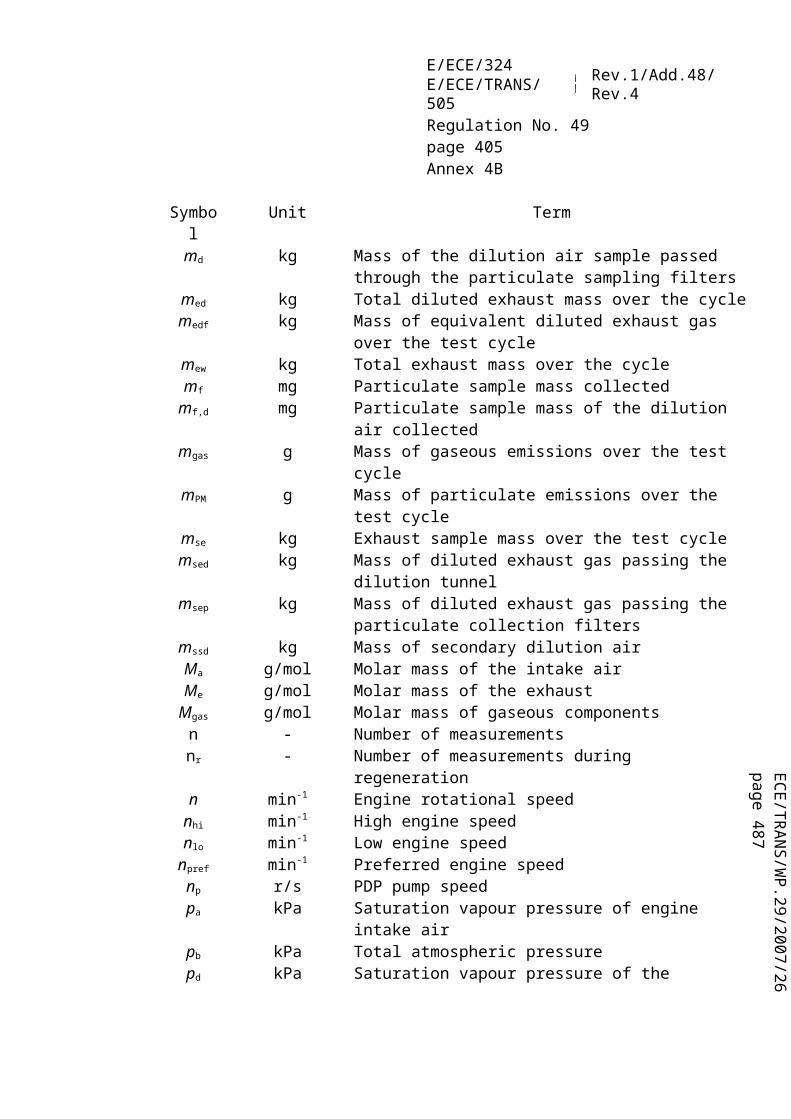
ECE/TR
AN
S/WP.29/2007/26
page 487
E/ECE/324E/ECE/TRANS/505 Rev.1/Add.48/Rev.4
Regulation No. 49page 405Annex 6
Calculation of Bessel averaged smoke (Annex 4A, Appendix 1, paragraph 7.3.2.):
In the following equation, the Bessel constants of the previous paragraph 2.2. are used. The actual unfiltered k-value, as calculated above, corresponds to S272 (Si). S271 (Si-1) and S270 (Si-2) are the two preceding unfiltered k-values, Y271 (Yi-1) and Y270 (Yi-2) are the two preceding filtered k-values.
Y272 = 0.542383 + 8.27277710-5 (0.427252 + 2 0.427392 + 0.427532 − 4 0.542337) + 0.968410 (0.542383 − 0.542337)
= 0.542389 m−1
This value corresponds to Ymax1,A in the following table.
Calculation of the final smoke value (Annex 4A, Appendix 1, paragraph 7.3.3.):
From each smoke trace, the maximum filtered k-value is taken for the further calculation. Assume the following values
Speed Ymax (m−1)Cycle 1 Cycle 2 Cycle 3
A 0.5424 0.5435 0.5587B 0.5596 0.5400 0.5389C 0.4912 0.5207 0.5177
SVA = (0.5424 + 0.5435 + 0.5587) / 3 = 0.5482 m− 1
SVB = (0.5596 + 0.5400 + 0.5389) / 3 = 0.5462 m− 1
SVC = (0.4912 + 0.5207 + 0.5177) / 3 = 0.5099 m− 1
SV = (0.43 0.5482) + (0.56 0.5462) + (0.01 0.5099) = 0.5467 m− 1
Cycle validation (Annex 4A, Appendix 1, paragraph 3.4.)
Before calculating SV, the cycle shall be validated by calculating the relative standard deviations of the smoke of the three cycles for each speed.
Speed Mean SV (m−1) absolute standard deviation (m−1)
relative standard deviation (per cent)
A 0.5482 0.0091 1.7B 0.5462 0.0116 2.1C 0.5099 0.0162 3.2
In this example, the validation criteria of 15 per cent are met for each speed.Table C
Values of opacity N, unfiltered and filtered k-value at beginning of load step

E/ECE/324E/ECE/TRANS/505 Rev.1/Add.48/Rev.4
Regulation No. 49page 406Annex 6
Index i Time Opacity N unfiltered k-value filtered k-value[−] [s] [per cent] [m−1] [m−1]− 2 0.000000 0.000000 0.000000 0.000000− 1 0.000000 0.000000 0.000000 0.0000000 0.000000 0.000000 0.000000 0.0000001 0.006667 0.020000 0.000465 0.0000002 0.013333 0.020000 0.000465 0.0000003 0.020000 0.020000 0.000465 0.0000004 0.026667 0.020000 0.000465 0.0000015 0.033333 0.020000 0.000465 0.0000026 0.040000 0.020000 0.000465 0.0000027 0.046667 0.020000 0.000465 0.0000038 0.053333 0.020000 0.000465 0.0000049 0.060000 0.020000 0.000465 0.00000510 0.066667 0.020000 0.000465 0.00000611 0.073333 0.020000 0.000465 0.00000812 0.080000 0.020000 0.000465 0.00000913 0.086667 0.020000 0.000465 0.00001114 0.093333 0.020000 0.000465 0.00001215 0.100000 0.192000 0.004469 0.00001416 0.106667 0.212000 0.004935 0.00001817 0.113333 0.212000 0.004935 0.00002218 0.120000 0.212000 0.004935 0.00002819 0.126667 0.343000 0.007990 0.00003620 0.133333 0.566000 0.013200 0.00004721 0.140000 0.889000 0.020767 0.00006122 0.146667 0.929000 0.021706 0.00008223 0.153333 0.929000 0.021706 0.00010924 0.160000 1.263000 0.029559 0.00014325 0.166667 1.455000 0.034086 0.00018526 0.173333 1.697000 0.039804 0.00023727 0.180000 2.030000 0.047695 0.00030128 0.186667 2.081000 0.048906 0.00037829 0.193333 2.081000 0.048906 0.00046930 0.200000 2.424000 0.057067 0.00057331 0.206667 2.475000 0.058282 0.00069332 0.213333 2.475000 0.058282 0.00082733 0.220000 2.808000 0.066237 0.00097734 0.226667 3.010000 0.071075 0.00114435 0.233333 3.253000 0.076909 0.00132836 0.240000 3.606000 0.085410 0.00153337 0.246667 3.960000 0.093966 0.00175838 0.253333 4.455000 0.105983 0.00200739 0.260000 4.818000 0.114836 0.00228340 0.266667 5.020000 0.119776 0.002587∼ ∼ ∼ ∼ ∼

ECE/TR
AN
S/WP.29/2007/26
page 487
E/ECE/324E/ECE/TRANS/505 Rev.1/Add.48/Rev.4
Regulation No. 49page 407Annex 6
Values of opacity N, unfiltered and filtered k-value around Ymax1,A (peak value, indicated in bold number)
Index i Time Opacity N unfiltered k-value filtered k-value[−] [s] [ per cent] [m−1] [m−1]∼ ∼ ∼ ∼ ∼
259 1.726667 17.182000 0.438429 0.538856260 1.733333 16.949000 0.431896 0.539423261 1.740000 16.788000 0.427392 0.539936262 1.746667 16.798000 0.427671 0.540396263 1.753333 16.788000 0.427392 0.540805264 1.760000 16.798000 0.427671 0.541163265 1.766667 16.798000 0.427671 0.541473266 1.773333 16.788000 0.427392 0.541735267 1.780000 16.788000 0.427392 0.541951268 1.786667 16.798000 0.427671 0.542123269 1.793333 16.798000 0.427671 0.542251270 1.800000 16.793000 0.427532 0.542337271 1.806667 16.788000 0.427392 0.542383272 1.813333 16.783000 0.427252 0.542389273 1.820000 16.780000 0.427168 0.542357274 1.826667 16.798000 0.427671 0.542288275 1.833333 16.778000 0.427112 0.542183276 1.840000 16.808000 0.427951 0.542043277 1.846667 16.768000 0.426833 0.541870278 1.853333 16.010000 0.405750 0.541662279 1.860000 16.010000 0.405750 0.541418280 1.866667 16.000000 0.405473 0.541136281 1.873333 16.010000 0.405750 0.540819282 1.880000 16.000000 0.405473 0.540466283 1.886667 16.010000 0.405750 0.540080284 1.893333 16.394000 0.416406 0.539663285 1.900000 16.394000 0.416406 0.539216286 1.906667 16.404000 0.416685 0.538744287 1.913333 16.394000 0.416406 0.538245288 1.920000 16.394000 0.416406 0.537722289 1.926667 16.384000 0.416128 0.537175290 1.933333 16.010000 0.405750 0.536604291 1.940000 16.010000 0.405750 0.536009292 1.946667 16.000000 0.405473 0.535389293 1.953333 16.010000 0.405750 0.534745294 1.960000 16.212000 0.411349 0.534079295 1.966667 16.394000 0.416406 0.533394296 1.973333 16.394000 0.416406 0.532691297 1.980000 16.192000 0.410794 0.531971298 1.986667 16.000000 0.405473 0.531233299 1.993333 16.000000 0.405473 0.530477300 2.000000 16.000000 0.405473 0.529704∼ ∼ ∼ ∼ ∼

E/ECE/324E/ECE/TRANS/505 Rev.1/Add.48/Rev.4
Regulation No. 49page 408Annex 6
3. ETC TEST
3.1. Gaseous emissions (diesel engine)
Assume the following test results for a PDP-CVS system
V0 (m3/rev) 0.1776Np (rev) 23073pB (kPa) 98.0p1 (kPa) 2.3T (K) 322.5
Ha (g/kg) 12.8NOx conce (ppm) 53.7NOx concd (ppm) 0.4COconce (ppm) 38.9COconcd (ppm) 1.0HCconce (ppm) 9.00HCconcd (ppm) 3.02
CO2,conce (per cent) 0.723Wact (kWh) 62.72
Calculation of the diluted exhaust gas flow (Annex 4A, Appendix 2, paragraph 4.1.):
MTOTW = 1.293 0.1776 23 073 (98.0 − 2.3) 273 / (101.3 322.5)= 423 7.2 kg
Calculation of the NOx correction factor (Annex 4A, Appendix 2, paragraph 5.3.):
Calculation of the background corrected concentrations (Annex 4A, Appendix 2, paragraph 5.4.1.):
Assuming a diesel fuel of the composition C1H1,8
NOx conc = 53.7 − 0.4 (1 − (1/18.69)) = 53.3 ppm

ECE/TR
AN
S/WP.29/2007/26
page 487
E/ECE/324E/ECE/TRANS/505 Rev.1/Add.48/Rev.4
Regulation No. 49page 409Annex 6
COconc = 38.9 − 1.0 (1 − (1/18.69)) = 37.9 ppm
HCconc = 9.00 − 3.02 (1 − (1/18.69)) = 6.14 ppm
Calculation of the emissions mass flow (Annex 4A, Appendix 2, paragraph 5.4.):NOx mass = 0.001587 53.3 1.039 423 7.2 = 372.391 gCOmass = 0.000966 37.9 423 7.2 = 155.129 gHCmass = 0.000479 6.14 423 7.2 = 12.462 g
Calculation of the specific emissions (Annex 4A, Appendix 2, paragraph 5.5.):xNO = 372.391/62.72 = 5.94 g/kWh
CO = 155.129/62.72 = 2.47 g/kWhHC = 12.462/62.72 = 0.199 g/kWh
3.2. Particulate emissions (diesel engine)
Assume the following test results for a PDP-CVS system with double dilution
MTOTW (kg) 4237.2Mf,p (mg) 3.030Mf,b (mg) 0.044MTOT (kg) 2.159MSEC (kg) 0.909Md (mg) 0.341MDIL (kg) 1.245
DF 18.69Wact (kWh) 62.72
Calculation of the mass emission (Annex 4A, Appendix 2, paragraph 6.2.1.):Mf = 3.030 + 0.044 = 3.074 mgMSAM = 2.159 − 0.909 = 1.250 kg
Calculation of the background corrected mass emission (Annex 4A, Appendix 2, paragraph 6.2.1.):

E/ECE/324E/ECE/TRANS/505 Rev.1/Add.48/Rev.4
Regulation No. 49page 410Annex 6
Calculation of the specific emission (Annex 4A, Appendix 2, paragraph 6.3.):PT = 10.42/62.72 = 0.166 g/kWhPT = 9.32/62.72 = 0.149 g/kWh, if background corrected
3.3. Gaseous emissions (CNG engine)
Assume the following test results for a PDP-CVS system with double dilution
MTOTW (kg) 4237.2Ha (g/kg) 12.8
NOx conce (ppm) 17.2NOx concd (ppm) 0.4COconce (ppm) 44.3COconcd (ppm) 1.0HCconce (ppm) 27.0HCconcd (ppm) 3.02CH4 conce (ppm) 18.0CH4 concd (ppm) 1.7
CO2,conce ( per cent) 0.723Wact (kWh) 62.72
Calculation of the NOx, correction factor (Annex 4A, Appendix 2, paragraph 5.3.):
Calculation of the NMHC concentration (Annex 4A, Appendix 2, paragraph 5.4.):
(a) GC methodNMHCconce = 27.0 − 18.0 = 9.0 ppm
(b) NMC method
Assuming a methane efficiency of 0.04 and an ethane efficiency of 0.98 (see Annex 4A, Appendix 5, paragraph 1.8.4.)
Calculation of the background corrected concentrations (Annex 4A, Appendix 2, paragraph 5.4.1.):
Assuming a G20 reference fuel (100 per cent methane) of the composition C1H4:

ECE/TR
AN
S/WP.29/2007/26
page 487
E/ECE/324E/ECE/TRANS/505 Rev.1/Add.48/Rev.4
Regulation No. 49page 411Annex 6
For NMHC, the background concentration is the difference between HCconcd and CH4concd
NOx conc = 17.2 − 0.4 (1 − (1/13.01)) = 16.8 ppmCOconc = 44.3 − 1.0 (1 − (1/13.01)) = 43.4 ppmNMHCconc = 8.4 − 1.32 (1 − (1/13.01)) = 7.2 ppmCH4 conc = 18.0 − 1.7 (1 − (1/13.01)) = 16.4 ppm
Calculation of the emissions mass flow (Annex 4A, Appendix 2, paragraph 5.4.):NOx mass = 0.001587 16.8 1.074 423 7.2 = 121.330 gCOmass = 0.000966 43.4 423 7.2 = 177.642 gNMHCmass = 0.000502 7.2 423 7.2 = 15.315 gCH4 mass = 0.000554 16.4 423 7.2 = 38.498 g
Calculation of the specific emissions (Annex 4A, Appendix 2, paragraph 5.5.):xNO = 121.330/62.72 = 1.93 g/kWh
CO = 177.642/62.72 = 2.83 g/kWhNMHC = 15.315/62.72 = 0.244 g/kWh
4CH = 38.498/62.72 = 0.614 g/kWh
4. Λ-SHIFT FACTOR (SΛ)
4.1. Calculation of the λ-shift factor (Sλ) 22/
100O
4mn
100inert%1
2S *2
λ
where:Sλ = λ-shift factor;inert per cent
= per cent by volume of inert gases in the fuel (i.e. N2, CO2, He, etc.);
*2O = per cent by volume of original oxygen in the fuel;
22/ Stoichiometric Air/Fuel ratios of automotive fuels - SAE J1829, June 1987. John B. Heywood, Internal combustion engine fundamentals, McGraw-Hill, 1988, Chapter 3.4 "Combustion stoichiometry" (pp. 68 to 72)

E/ECE/324E/ECE/TRANS/505 Rev.1/Add.48/Rev.4
Regulation No. 49page 412Annex 6
N and m = refer to average CnHm representing the fuel hydrocarbons, i.e:
100%diluent 1
..100
%C5
100%C
4100
%C3
100%C
2100
%CH1
n
54324
100%diluent 1
..100
%HC...8
100%HC
6100
%HC4
100%CH
4m
8362424
where:CH4 = per cent by volume of methane in the fuel;C2 = per cent by volume of all C2 hydrocarbons (e.g.: C2H6, C2H4, etc.) in the
fuel;C3 = per cent by volume of all C3 hydrocarbons (e.g.: C3H8, C3H6, etc.) in the
fuel;C4 = per cent by volume of all C4 hydrocarbons (e.g.: C4H10, C4H8, etc.) in the
fuelC5 = per cent by volume of all C5 hydrocarbons (e.g.: C5H12, C5H10, etc.) in the
fuel;diluent = per cent by volume of dilution gases in the fuel (i.e.: O2*, N2, CO2, He, etc.).
4.2. Examples for the calculation of the λ-shift factor Sλ:
Example 1: G25: CH4 = 86 per cent, N2 = 14 per cent (by volume)

ECE/TR
AN
S/WP.29/2007/26
page 487
E/ECE/324E/ECE/TRANS/505 Rev.1/Add.48/Rev.4
Regulation No. 49page 413Annex 6
Example 2: GR: CH4 = 87 per cent, C2H6 = 13 per cent (by vol)
Example 3: USA: CH4 = 89 per cent, C2H6 = 4.5 per cent, C3H8 = 2.3 per cent, C6H14 = 0.2 per cent, O2 = 0.6 per cent, N2 = 4 per cent

E/ECE/324E/ECE/TRANS/505 Rev.1/Add.48/Rev.4
Regulation No. 49page 414Annex 7
Annex 7
PROCEDURES FOR CONDUCTING THE TEST FOR DURABILITY OF EMISSION CONTROL SYSTEMS
1. INTRODUCTION
This annex details the procedures for selecting a family of engines to be tested over a service accumulation schedule for the purpose of determining deterioration factors. Such deterioration factors will be applied to the measured emissions from engines undergoing a periodical audit to ensure that in-service engine emissions remain in conformity with the applicable emission limits, as given in the tables in paragraph 5.2.1. to this Regulation, over the durability period applicable to the vehicle in which the engine is installed.
This annex also details the emission and non-emission-related maintenance that will be carried out on engines undergoing a service accumulation schedule. Such maintenance will be performed on in-service engines and communicated to owners of new heavy-duty engines.
2. SELECTION OF ENGINES FOR ESTABLISHING USEFUL LIFE DETERIORATION FACTORS
2.1. Engines will be selected from the engine family defined in paragraph 7.1. to this Regulation for emission testing to establish useful life deterioration factors.
2.2. Engines from different engine families may be further combined into families based on the type of exhaust aftertreatment system utilised. In order to place engines with different numbers of cylinders and different cylinder configuration but having the same technical specifications and installation for the exhaust aftertreatment systems into the same engine-aftertreatment system family, the manufacturer shall provide data to the Approval Authority that demonstrates that the emissions of such engines are equivalent.
2.3. One engine representing the engine-aftertreatment system family shall be selected by the engine manufacturer for testing over the service accumulation schedule defined in paragraph 3.2. of this annex, according to the criteria for selecting engines given in paragraph 7.2. to this Regulation and shall be reported to the Approval Authority before any testing commences.
2.3.1. If the Approval Authority decides that the worst case emission rate of the engine-aftertreatment system family can be characterized better by another engine then the test engine shall be selected by the Approval Authority after consultation with the engine manufacturer.

ECE/TR
AN
S/WP.29/2007/26
page 487
E/ECE/324E/ECE/TRANS/505 Rev.1/Add.48/Rev.4
Regulation No. 49page 415Annex 7
3. ESTABLISHING USEFUL LIFE DETERIORATION FACTORS
3.1. General
Deterioration factors applicable to an engine-aftertreatment system family are developed from the selected engines based on a distance and service accumulation procedure that includes periodic testing for gaseous and particulate emissions over the ESC and ETC tests.
3.2. Service accumulation schedule
Service accumulation schedules may be carried out at the choice of the manufacturer by running a vehicle equipped with the selected parent engine over an "in-service accumulation" schedule or by running the selected parent engine over a "dynamometer service accumulation" schedule.
3.2.1. In-service and dynamometer service accumulation
3.2.1.1. The manufacturer shall determine the form and extent of the distance and service accumulation for engines, consistent with good engineering practice.
3.2.1.2. The manufacturer will determine when the engine will be tested for gaseous and particulate emissions over the ESC and ETC tests.
3.2.1.3. A single engine-operating schedule shall be used for all engines in an engine-aftertreatment system family.
3.2.1.4. At the request of the manufacturer and with the agreement of the Approval Authority, only one test cycle (either the ESC or ETC test) need be run at each test point with the other test cycle run only at the beginning and at the end of the service accumulation schedule.
3.2.1.5. Operating schedules may be different for different engine-aftertreatment system families.
3.2.1.6. Operating schedules may be shorter than the useful life period provided that the number of test points allows for a proper extrapolation of the test results, according to paragraph 3.5.2. In any case, the service accumulation shall not be shorter than shown in the table in paragraph 3.2.1.8.
3.2.1.7. The manufacturer has to provide the applicable correlation between minimum service accumulation period (driving distance) and engine dynamometer hours, for example, fuel consumption correlation, vehicle speed versus engine revolutions correlation etc.

E/ECE/324E/ECE/TRANS/505 Rev.1/Add.48/Rev.4
Regulation No. 49page 416Annex 7
3.2.1.8. Minimum service accumulation
Category of vehicle in which engine will be installed
Minimum service accumulation period
Useful life (paragraph of this Regulation)
Category N1 vehicles 100,000 km Paragraph 5.3.1.1.Category N2 vehicles 125,000 km Paragraph 5.3.1.2.Category N3 vehicles with a maximum technically permissible mass not exceeding 16 tonnes
125,000 km Paragraph 5.3.1.2.
Category N3 vehicles with a maximum technically permissible mass exceeding 16 tonnes
167,000 km Paragraph 5.3.1.3.
Category M2 vehicles 100,000 km Paragraph 5.3.1.1.Category M3 vehicles of classes I, II, A and B, with a maximum technically permissible mass not exceeding 7.5 tonnes
125,000 km Paragraph 5.3.1.2.
Category M3 vehicles of classes III and B, with a maximum technically permissible mass exceeding 7.5 tonnes
167,000 km Paragraph 5.3.1.3.
3.2.1.9. The in-service accumulation schedule shall be fully described in the application for approval and reported to the Approval Authority before the start of any testing.
3.2.2. If the Approval Authority decides that additional measurements need to be carried out on the ESC and ETC tests between the points selected by the manufacturer it shall notify the manufacturer. The revised in-service accumulation schedule or dynamometer service accumulation schedule shall be prepared by the manufacturer and agreed by the Approval Authority.
3.3. Engine testing
3.3.1. Start of the service accumulation schedule
3.3.1.1. For each engine-aftertreatment system family, the manufacturer shall determine the number of hours of engine running after which the operation of the engine-after-treatment system has stabilised. If requested by the Approval Authority the manufacturer shall make available the data and analysis used to make this determination. As an alternative, the manufacturer may elect to run the engine for 125 hours to stabilise the engine-aftertreatment system.
3.3.1.2. The stabilisation period determined in paragraph 3.3.1.1. will be deemed to be the start of the service accumulation schedule.

ECE/TR
AN
S/WP.29/2007/26
page 487
E/ECE/324E/ECE/TRANS/505 Rev.1/Add.48/Rev.4
Regulation No. 49page 417Annex 7
3.3.2. Service accumulation testing
3.3.2.1. After stabilisation, the engine will be run over the service accumulation schedule selected by the manufacturer, as described in paragraph 3.2. above. At the periodic intervals in the service accumulation schedule determined by the manufacturer, and, where appropriate, also stipulated by the Approval Authority according to paragraph 3.2.2., the engine shall be tested for gaseous and particulate emissions over the ESC and ETC tests. In accordance with paragraph 3.2., if it has been agreed that only one test cycle (ESC or ETC) be run at each test point, the other test cycle (ESC or ETC) shall be run at the beginning and end of the service accumulation schedule.
3.3.2.2. During the service accumulation schedule, maintenance will be carried out on the engine according to paragraph 4.
3.3.2.3. During the service accumulation schedule, unscheduled maintenance on the engine or vehicle may be performed, for example if the OBD system has specifically detected a problem that has resulted in the malfunction indicator (MI) being activated.
3.4. Reporting
3.4.1. The results of all emission tests (ESC and ETC) conducted during the service accumulation schedule shall be made available to the Approval Authority. If any emission test is declared to be void, the manufacturer shall provide an explanation of why the test has been declared void. In such a case, another series of emission tests over the ESC and ETC tests shall be carried out within a further 100 hours of service accumulation.
3.4.2. Whenever a manufacturer tests an engine over a service accumulation schedule for the establishment of deterioration factors, the manufacturer shall retain in its records all information concerning all the emission tests and maintenance carried out on the engine during the service accumulation schedule. This information shall be submitted to the Approval Authority along with the results of the emission tests conducted over the service accumulation schedule.
3.5. Determination of deterioration factors
3.5.1. For each pollutant measured on the ESC and ETC tests and at each test point during the service accumulation schedule, a "best fit" regression analysis shall be made on the basis of all test results. The results of each test for each pollutant shall be expressed to the same number of decimal places as the limit value for that pollutant, as shown in the tables in paragraph 5.2.1. to this Regulation, plus one additional decimal place. In accordance with paragraph 3.2., if it has been agreed that only one test cycle (ESC or ETC) be run at each test point and the other test cycle (ESC or ETC) run only at the

E/ECE/324E/ECE/TRANS/505 Rev.1/Add.48/Rev.4
Regulation No. 49page 418Annex 7
beginning and end of the service accumulation schedule, the regression analysis shall be made only on the basis of the test results from the test cycle run at each test point.
3.5.2. On the basis of the regression analysis, the manufacturer shall calculate the projected emission values for each pollutant at the start of the service accumulation schedule and at the useful life that is applicable for the engine under test by extrapolation of the regression equation as determined in paragraph 3.5.1.
3.5.3. For engines not equipped with an exhaust aftertreatment system, the deterioration factor for each pollutant is the difference between the projected emission values at the useful life period and at the start of the service accumulation schedule.
For engines equipped with an exhaust aftertreatment system, the deterioration factor for each pollutant is the ratio of the projected emission values at the useful life period and at the start of the service accumulation schedule.
In accordance with paragraph 3.2., if it has been agreed that only one test cycle (ESC or ETC) be run at each test point and the other test cycle (ESC or ETC) run only at the beginning and end of the service accumulation schedule, the deterioration factor calculated for the test cycle that has been run at each test point shall be applicable also for the other test cycle, provided that for both test cycles, the relationship between the measured values run at the beginning and at the end of the service accumulation schedule are similar.
3.5.4. The deterioration factors for each pollutant on the appropriate test cycles shall be recorded in paragraph 1.4. of Appendix 1 to Annex 6 to this Regulation.
3.6. As an alternative to using a service accumulation schedule to determine deterioration factors, engine manufacturers may choose to use the following deterioration factors:
Engine type Test cycle CO HC NMHC CH4 NOx PMDiesel engine
ESC 1.1 1.05 - - 1.05 1.1ETC 1.1 1.05 - - 1.05 1.1
Gas engine ETC 1.1 1.05 1.05 1.2 1.05 -
3.6.1. The manufacturer may select to carry across the DF's determined for an engine or engine/aftertreatment combination to engines or engine/aftertreatment combinations that do not fall into the same engine family category as determined according to paragraph 2.1. In such cases, the manufacturer shall demonstrate to the Approval Authority that the base engine or engine/aftertreatment combination and the engine or engine/aftertreatment combination for which the DF's are being carried over have the same technical specifications and installation requirements on the vehicle and that the emissions of such engine or engine/aftertreatment combinations are similar.

ECE/TR
AN
S/WP.29/2007/26
page 487
E/ECE/324E/ECE/TRANS/505 Rev.1/Add.48/Rev.4
Regulation No. 49page 419Annex 7
3.7. Checking of conformity of production
3.7.1. Conformity of production for emissions compliance is checked on the basis of paragraph 8. to this Regulation.
3.7.2. At the time of approval, the manufacturer may choose to measure at the same time the pollutant emissions before any exhaust aftertreatment system. In so doing, the manufacturer may develop an informal deterioration factor separately for the engine and the aftertreatment system that may be used by the manufacturer as an aid to end of production line auditing.
3.7.3. For the purposes of approval, only the deterioration factors adopted by the manufacturer from paragraph 3.6.1. or the deterioration factors developed according to paragraph 3.5. shall be recorded in paragraph 1.4. of Appendix 1 to Annex 6 to this Regulation.
4. MAINTENANCE
During the service accumulation schedule, maintenance performed on engines and proper consumption of any required reagent used to determine deterioration factors are classified as either emission-related or non-emission-related and each of these can be classified as scheduled and unscheduled. Some emission-related maintenance is also classified as critical emission-related maintenance.
4.1. Emission-related scheduled maintenance
4.1.1. This paragraph specifies emission-related scheduled maintenance for the purpose of conducting a service accumulation schedule and for inclusion in the maintenance instructions furnished to owners of new heavy-duty vehicles and heavy-duty engines.
4.1.2. All emission-related scheduled maintenance for purposes of conducting a service accumulation schedule shall occur at the same or equivalent distance intervals that will be specified in the manufacturer's maintenance instructions to the owner of the heavy-duty vehicle or heavy-duty engine. This maintenance schedule may be updated as necessary throughout the service accumulation schedule provided that no maintenance operation is deleted from the maintenance schedule after the operation has been performed on the test engine.
4.1.3. Any emission-related maintenance performed on engines shall be necessary to assure in-use conformity with the relevant emission standards. The manufacturer shall submit data to the Approval Authority to demonstrate that all of the emission-related scheduled maintenance is technically necessary.
4.1.4. The engine manufacturer shall specify the adjustment, cleaning and maintenance (where necessary) of the following items:

E/ECE/324E/ECE/TRANS/505 Rev.1/Add.48/Rev.4
Regulation No. 49page 420Annex 7
(a) Filters and coolers in the exhaust gas re-circulation system ;(b) Positive crankcase ventilation valve;(c) Fuel injector tips (cleaning only);(d) Fuel injectors;(e) Turbocharger;(f) Electronic engine control unit and its associated sensors and actuators;(g) Particulate filter system (including related components);(h) Exhaust gas re-circulation system, including all related control valves and tubing;(i) Any exhaust aftertreatment system.
4.1.5. For the purposes of maintenance, the following components are defined as critical emission-related items:(a) Any exhaust aftertreatment system;(b) Electronic engine control unit and its associated sensors and actuators;(c) Exhaust gas re-circulation system including all related filters, coolers, control
valves and tubing;(d) Positive crankcase ventilation valve.
4.1.6. All critical emission-related scheduled maintenance shall have a reasonable likelihood of being performed in-use. The manufacturer shall demonstrate to the Approval Authority the reasonable likelihood of such maintenance being performed in-use and such demonstration shall be made prior to the performance of the maintenance during the service accumulation schedule.
4.1.7. Critical emission-related scheduled maintenance items that satisfy any of the conditions defined in paragraphs 4.1.7.1. to 4.1.7.4. will be accepted as having a reasonable likelihood of the maintenance item being performed in-use.
4.1.7.1. Data is submitted which establishes a connection between emissions and vehicle performance such that as emissions increase due to lack of maintenance, vehicle performance will simultaneously deteriorate to a point unacceptable for typical driving.
4.1.7.2. Survey data is submitted which demonstrates that, at an 80 per cent confidence level, 80 per cent of such engines already have this critical maintenance item performed in-use at the recommended interval(s).
4.1.7.3. In association with the requirements of paragraph 3.6. of Annex 9A to this Regulation, a clearly visible indicator shall be installed on the dashboard of the vehicle to alert the driver that maintenance is due. The indicator shall be actuated at the appropriate distance or by component failure. The indicator shall remain activated while the engine is in operation and shall not be erased without the required maintenance being carried out. Re-setting of the signal shall be a required step in the maintenance schedule. The system shall not be designed to deactivate upon the end of the appropriate useful life period of the engine or thereafter.

ECE/TR
AN
S/WP.29/2007/26
page 487
E/ECE/324E/ECE/TRANS/505 Rev.1/Add.48/Rev.4
Regulation No. 49page 421Annex 7
4.1.7.4. Any other method which the Approval Authority determines as establishing a reasonable likelihood that the critical maintenance will be performed in-use.
4.2. Changes to scheduled maintenance
4.2.1. The manufacturer shall submit a request to the Approval Authority for approval of any new scheduled maintenance that it wishes to perform during the service accumulation schedule and thereby recommend to owners of heavy-duty vehicles and engines. The manufacturer shall also include its recommendation as to the category (i.e. emission-related, non-emission-related, critical or non-critical) of the new scheduled maintenance being proposed and, for emission-related maintenance, the maximum feasible maintenance interval. The request shall be accompanied by data supporting the need for the new scheduled maintenance and the maintenance interval.
4.3. Non-emission-related scheduled maintenance
4.3.1. Non-emission-related scheduled maintenance which is reasonable and technically necessary (e.g. oil change, oil filter change, fuel filter change, air filter change, cooling system maintenance, idle speed adjustment, governor, engine bolt torque, valve lash, injector lash, timing, adjustment of the tension of any drive-belt, etc) may be performed on engines or vehicles selected for the service accumulation schedule at the least frequent intervals recommended by the manufacturer to the owner (e.g. not at the intervals recommended for severe service).
4.4. Maintenance on engines selected for testing over a service accumulation schedule
4.4.1. Repairs to the components of an engine selected for testing over a service accumulation schedule other than the engine, emission control system or fuel system shall be performed only as a result of part failure or engine system malfunction.
4.4.2. Equipment, instruments or tools may not be used to identify malfunctioning, maladjusted or defective engine components unless the same or equivalent equipment, instruments or tools will be available to dealerships and other service outlets and,(a) Are used in conjunction with scheduled maintenance on such components, and;(b) Are used subsequent to the identification of an engine malfunction.
4.5. Critical emission-related unscheduled maintenance
4.5.1. The consumption of a required reagent is defined as critical emission-related unscheduled maintenance for the purpose of conducting a service accumulation schedule and for inclusion in the maintenance instructions furnished by manufacturers to owners of new heavy-duty vehicles or heavy-duty engines.

E/ECE/324E/ECE/TRANS/505 Rev.1/Add.48/Rev.4
Regulation No. 49page 422Annex 8
Annex 8
CONFORMITY OF IN-SERVICE VEHICLES/ENGINES
1. GENERAL
1.1. With reference to approvals granted for emissions, measures are appropriate for confirming the functionality of the emission control devices during the useful life of an engine installed in a vehicle under normal conditions of use (conformity of in-service vehicles/engines properly maintained and used).
1.2. For the purpose of this Regulation these measures shall be checked over a period corresponding to the appropriate useful life period defined in paragraph 5.3. of this Regulation for vehicles or engines which are approved to either row B1, row B2 or row C of the tables in paragraph 5.2.1. of this Regulation.
1.3. The checking of conformity of in-service vehicles/engines is done on the basis of information provided by the manufacturer to the Approval Authority conducting an audit of the emissions-performance of a range of representative vehicles or engines of which the manufacturer holds the approval.
Figures 1 in this annex illustrates the procedure for in-service conformity checking.
2. PROCEDURES FOR AUDIT
2.1. Audit of in-service conformity by the Approval Authority is conducted on the basis of any relevant information that the manufacturer has, under procedures similar to those defined in Appendix 2 of the 1958 Agreement (E/ECE/324-E/ECE/TRANS/505/Rev.2). Alternatives are in-service monitoring reports supplied by the manufacturer, Approval Authority surveillance testing and/or information on surveillance testing performed by a Contracting Party. The procedures to be used are given in paragraph 3.
3. AUDIT PROCEDURES
3.1. An audit of in-service conformity will be conducted by the Approval Authority on the basis of information supplied by the manufacturer. The manufacturer's in-service monitoring (ISM) report should be based on in-use testing of engines or vehicles using proven and relevant testing protocols. Such information (the ISM report) shall include, but is not limited to, the following (see paragraphs 3.1.1. to 3.1.13.):
3.1.1. The name and address of the manufacturer.
3.1.2. The name, address, telephone and fax numbers and e-mail address of his authorized representative within the areas covered by the manufacturer's information.

ECE/TR
AN
S/WP.29/2007/26
page 487E/ECE/324E/ECE/TRANS/505 Rev.1/Add.48/Rev.4
Regulation No. 49page 423Annex 8
Figure 1. In-service conformity checking – audit procedure
NO
YES
NO
Manufacturer submits in-service conformity report to
AA(a) for audit
YESAA(a) reviews
manufacturer's in-service conformity report
Does the AA(a) accept that
manufacturer's in-serviceconformity report confirms acceptability of a vehicle or
engine type within the family? (paragraph 3.4. of
this annex)
Process Completed.No further action
required.
YES
Manufacturer provides or
obtains additional
information or test data.
Manufacturer compiles new
in-service conformity
report.
Does AA(a) decide that
information is insufficient to reach
a decision?
NO
AA(a) begins formal testing of suspect engine type or family (as described in paragraph 5. of this
annex )
Does the AA(a)
decide to audit the manufacturer's
compliance data for this vehicle or engine type or
family?
Manufacturer files report for future reference
Vehicle or engine manufacturer and Approval Authority complete vehicle or engine approval for the new vehicle or engine type.
Approval Authority (AA) grants approval.
Manufacture and sales of approved vehicle or engine type.
Vehicle or engine manufacturer develops own in-service conformity procedure
Vehicle or engine manufacturer carries out own in-service conformity procedure (vehicle or engine type or family)
Vehicle manufacturer compiles report of the in-house procedure (including all data required by paragraph 3. of this
annex)
In-house in-service
conformity report for approved
vehicle or engine type or family
START
(a) In this case, AA means the Approval Authority that granted the approval.
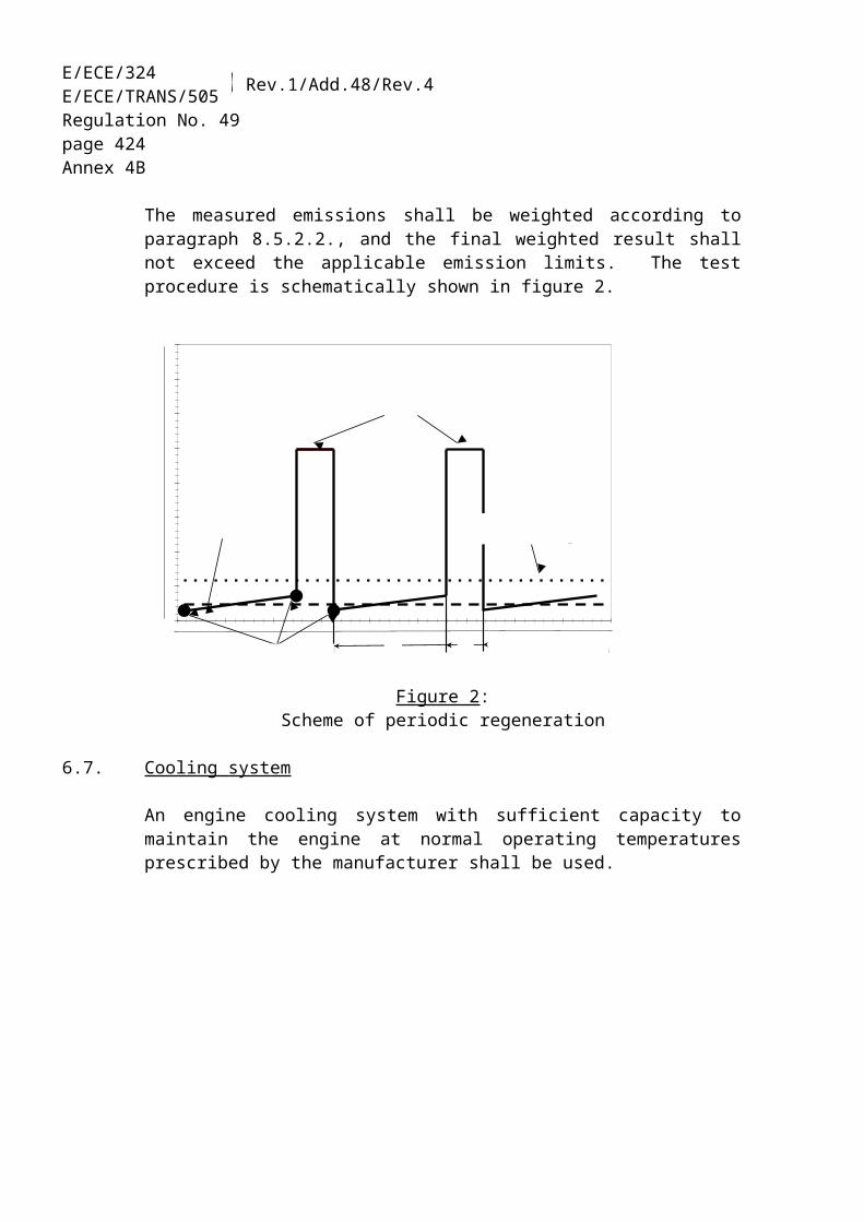
E/ECE/324E/ECE/TRANS/505 Rev.1/Add.48/Rev.4
Regulation No. 49page 424Annex 8
3.1.3. The model name(s) of the engines included in the manufacturer's information.
3.1.4. The list of engine types covered within the manufacturer's information, i.e. the engine-after-treatment system family.
3.1.5. The vehicle identification number (VIN) codes applicable to the vehicles equipped with an engine that is part of the audit.
3.1.6. The numbers of the type approvals applicable to the engine types within the in-service family, including, where applicable, the numbers of all extensions and field fixes/recalls (re-works):
3.1.7. Details of extensions, field fixes/recalls to those type approvals for the engines covered within the manufacturer's information (if requested by the Approval Authority).
3.1.8. The period of time over which the manufacturer's information was collected.
3.1.9. The engine build period covered within the manufacturer's information (e.g. "vehicles or engines manufactured during the 2005 calendar year").
3.1.10. The manufacturer's in-service conformity checking procedure, including:
3.1.10.1. Vehicle or engine location method;
3.1.10.2. Selection and rejection criteria for vehicle or engine;
3.1.10.3. Test types and procedures used for the programme;
3.1.10.4. The manufacturer's acceptance/rejection criteria for the in-service family group;
3.1.10.5. Geographical area(s) within which the manufacturer has collected information;
3.1.10.6. Sample size and sampling plan used.
3.1.11. The results from the manufacturer's in-service conformity procedure, including:
3.1.11.1. Identification of the engines included in the programme (whether tested or not). The identification will include:(a) model name;(b) vehicle identification number (VIN);(c) engine identification number;(d) vehicle registration number equipped with an engine that is part of the audit;

ECE/TR
AN
S/WP.29/2007/26
page 487
E/ECE/324E/ECE/TRANS/505 Rev.1/Add.48/Rev.4
Regulation No. 49page 425Annex 8
(e) date of manufacture;(f) region of use (where known);(g) type of use of the vehicle (where known), i.e. urban delivery, long haul etc.
3.1.11.2. The reason(s) for rejecting a vehicle or engine from a sample (e.g., vehicle being in-use for less than one year, improper emission-related maintenance, evidence of using a fuel having a higher sulphur content than required for normal vehicle use, emission control equipment not in conformity with approval). The reason for rejection shall be substantiated (e.g., the nature of non-fulfilment of maintenance instructions, etc.). A vehicle should not be excluded solely on the ground that the AECS may have been excessively in operation.
3.1.11.3. Emission-related servicing and maintenance history for each engine in the sample (including any re-works).
3.1.11.4. Repair history for each engine in the sample (where known).
3.1.11.5. Test data, including:(a) date of test;(b) location of test;(c) distance indicated odometer of vehicle equipped with an engine that is covered
by the audit;(d) test fuel specifications (e.g. test reference fuel or market fuel);(e) test conditions (temperature, humidity, dynamometer inertia weight);(f) dynamometer settings (e.g. power setting);(g) emission test results conducted on the ESC, ETC and ELR tests according to
paragraph 4. of this annex. A minimum of five engines shall be tested;(h) alternative to item (g) above, tests may be conducted using another protocol.
The relevance for monitoring in-service functionality with such a test shall be stated and substantiated by manufacturer in conjunction with the approval process (paragraphs 3. and 4. of this Regulation).
3.1.12. Records of indication from the OBD system.
3.1.13. Record of experiences of the use of consumable reagent. Reports should detail, but not be limited to, operator experiences with the handling of filling, refilling and consumption of the reagent, and the conduct of the filling installations, and, specifically, the frequency of activation in-use of the temporary performance limiter and events of other defect instances, activation of the MI and the registering of a fault code relating to a lack of the consumable reagent.
3.1.13.1. The manufacturer shall supply in-use and defect reports. The manufacturer shall report on warranty claims and their nature, and in-field indications of activation/ deactivation of the MI and the registering of a fault code relating to a lack of the

E/ECE/324E/ECE/TRANS/505 Rev.1/Add.48/Rev.4
Regulation No. 49page 426Annex 8
consumable reagent and the activation/deactivation of the engine performance limiter (see paragraph 5.5.5. of this Regulation).
3.2. The information gathered by the manufacturer shall be sufficiently comprehensive to ensure that in-service performance can be assessed for normal conditions over the appropriate durability/useful life period defined in paragraph 5.3. of this Regulation and in a way representative of the manufacturer's geographic penetration.
3.3. The manufacturer may whish to run in-service monitoring comprising fewer engines/vehicles than the number given in paragraph 3.1.11.5., item (g), and using a procedure defined under paragraph 3.1.11.5., item (h). The reason could be that the engines in the engine family(-ies) covered by the report are in a small number. The conditions should have been agreed on beforehand by the Approval Authority.
3.4. On the basis of the monitoring report referred to in this paragraph, the Approval Authority shall either:(a) decide that the in-service conformity of an engine type or an engine family is
satisfactory and not to take any further action;(b) decide that the data provided by the manufacturer is insufficient to reach a
decision and request additional information and/or test data from the manufacturer. Where requested, and depending on the approval of the engine, such additional test data shall include ESC, ELR, and ETC test results, or from other proven procedures according to paragraph 3.1.11.5., item (h);
(c) decide that the in-service conformity of an engine family is unsatisfactory and proceed to have confirmatory testing carried out on a sample of engines from the engine family, according to paragraph 5. of this annex.
3.5. A Contracting Party may conduct and report its surveillance testing, based on the audit procedure spelled out in this paragraph. Information on the procurement, maintenance, and manufacturer's participation in the activities may be recorded. Likewise, the Contracting Party may use alternative emission test protocols, according to paragraph 3.1.11.5., item (h).
3.6. The Approval Authority may take up surveillance testing conducted and reported by a Contracting Party as a basis for the decisions according to paragraph 3.4.
3.7. The manufacturer should report to the Approval Authority and the Contracting Party(s) where the subject engines/vehicles are kept in service when planning to conduct a voluntary remedial action. The reporting shall be supplied by the manufacturer in conjunction with taking the decision to take action, specifying the particulars of the action, describe the groups of engines/vehicles to be included in the action, and regularly thereafter on the commencement of the campaign. The applicable particulars of paragraph 7. of this annex may be used.

ECE/TR
AN
S/WP.29/2007/26
page 487
E/ECE/324E/ECE/TRANS/505 Rev.1/Add.48/Rev.4
Regulation No. 49page 427Annex 8
4. EMISSION TESTS
4.1. An engine selected from the engine family shall be tested over the ESC and ETC test cycles for gaseous and particulate emissions and over the ELR test cycle for smoke emission. The engine shall be representative of the type of use expected for this type of engine, and come from a vehicle in normal use. The procurement, inspection, and restorative maintenance of the engine/vehicle shall be conducted using a protocol such as is specified in paragraph 3., and shall be documented.
The appropriate maintenance schedule, referred to in paragraph 4. of Annex 7, shall have been carried out on the engine.
4.2. The emission values determined from the ESC, ETC and ELR tests shall be expressed to the same number of decimal places as the limit value for that pollutant, as shown in the tables in paragraph 5.2.1. of this Regulation, plus one additional decimal place.
5. CONFIRMATORY TESTING
5.1. Confirmatory testing is done for the purpose of confirmation of the in-service emission functionality of an engine family.
5.1.1. If the Approval Authority is not satisfied with the manufacturers" ISM according to paragraph 3.4. or on a reported evidence of unsatisfactory in-service conformity, e.g., according to paragraph 3.5., may order the manufacturer to run test for confirmatory purposes. The Approval Authority will examine the confirmatory test report supplied by the manufacturer.
5.1.2. The Approval Authority may conduct confirmatory testing.
5.2. The confirmatory test should be applicable to engine ESC, ETC and ELR tests, as specified in paragraph 4. Representative engines to be tested should be dismounted from vehicles used under normal conditions and be tested. Alternatively, after prior agreement with the Approval Authority, the manufacturer may test emission control components from vehicles in use, after being dismounted, transferred and mounted on properly used and representative engine(s). For each series of tests, the same package of emission control components shall be selected. The reason for the selection shall be stated.
5.3. A test result may be regarded as non-satisfactory when, from tests of two or more engines representing the same engine family, for any regulated pollutant component, the limit value as shown in paragraph 5.2.1. of this Regulation is exceeded significantly.

E/ECE/324E/ECE/TRANS/505 Rev.1/Add.48/Rev.4
Regulation No. 49page 428Annex 8
6. ACTIONS TO BE TAKEN
6.1. Where the Approval Authority is not satisfied with the information or test data supplied by the manufacturer, and, having carried out confirmatory engine testing according to paragraph 5., or based on confirmatory testing conducted by a Contracting Party (paragraph 5.3.), and it is certain that an engine type is not in conformity with the requirements of these provisions, the Approval Authority shall request the manufacturer to submit a plan of remedial measure to remedy the non-conformity.
6.2. In this case, the remedial measures referred to in Appendix 2 of the 1958 Agreement (E/ECE/324-E/ECE/TRANS/505/Rev.2) are extended to engines in service belonging to the same vehicle type which are likely to be affected with the same defects, in accordance with paragraph 8. of this Regulation.
To be valid the plan of remedial measures presented by the manufacturer shall be approved by the Approval Authority. The manufacturer is responsible for the execution of the remedial plan as approved.
The Approval Authority shall notify its decision to all Contracting Parties within 30 days. The Contracting Parties may require that the same plan of remedial measures be applied to all engines of the same type registered in their territory.
6.3. If a Contracting Party to the Agreement has established that a vehicle type does not conform to the applicable requirements of this annex, it shall notify without delay the Contracting Party to the Agreement which granted the original type approval in accordance with the requirements of the Agreement.
Then, subject to the provision of the Agreement, the Competent Authority of the Contracting Party to the Agreement which granted the original type approval shall inform the manufacturer that a vehicle type fails to satisfy the requirements of these provisions and that certain measures are expected from the manufacturer. The manufacturer shall submit to the authority, within two months after this notification, a plan of measures to overcome the defects, the substance of which should correspond with the requirements of paragraph 7. The Competent Authority which granted the original approval shall, within two months, consult the manufacturer in order to secure agreement on a plan of measures and on carrying out the plan. If the Competent Authority which granted the original type approval establishes that no agreement can be reached, the relevant procedures to the Agreement shall be initiated.
7. PLAN OF REMEDIAL MEASURES
7.1. The plan of remedial measures, requested according to paragraph 6.1, shall be filed with the Approval Authority not later than 60 working days from the date of the notification referred to in paragraph 6.2. The Approval Authority shall within 30 working days

ECE/TR
AN
S/WP.29/2007/26
page 487
E/ECE/324E/ECE/TRANS/505 Rev.1/Add.48/Rev.4
Regulation No. 49page 429Annex 8
declare its approval or disapproval of the plan of remedial measures. However, where the manufacturer can demonstrate to the satisfaction of the competent Approval Authority, that further time is required to investigate the non-compliance in order to submit a plan of remedial measures, an extension is granted.
7.2. The remedial measures shall apply to all engines likely to be affected by the same defect. The need to amend the approval documents shall be assessed.
7.3. The manufacturer shall provide a copy of all communications related to the plan of remedial measures, shall also maintain a record of the recall campaign, and supply regular status reports to the Approval Authority.
7.4. The plan of remedial measures shall include the requirements specified in paragraphs 7.4.1. to 7.4.11. The manufacturer shall assign a unique identifying name or number to the plan of remedial measures.
7.4.1. A description of each engine type included in the plan of remedial measures.
7.4.2. A description of the specific modifications, alterations, repairs, corrections, adjustments, or other changes to be made to bring the engines into conformity including a brief summary of the data and technical studies which support the manufacturer's decision as to the particular measures to be taken to correct the non-conformity.
7.4.3. A description of the method by which the manufacturer informs the engine or vehicle owners about the remedial measures.
7.4.4. A description of the proper maintenance or use, if any, which the manufacturer stipulates as a conditions of eligibility for repair under the plan of remedial measures, and an explanation of the manufacturer's reasons for imposing any such condition. No maintenance or use conditions may be imposed unless it is demonstrably related to the non-conformity and the remedial measures.
7.4.5. A description of the procedure to be followed by engine owners to obtain correction of the non-conformity. This shall include a date after which the remedial measures may be taken, the estimated time for the workshop to perform the repairs and where they can be done. The repair shall be done expediently, within a reasonable time after delivery of the vehicle.
7.4.6. A copy of the information transmitted to the vehicle owner.
7.4.7. A brief description of the system which the manufacturer uses to assure an adequate supply of component or systems for fulfilling the remedial action. It shall be indicated when there will be an adequate supply of components or systems to initiate the campaign.

E/ECE/324E/ECE/TRANS/505 Rev.1/Add.48/Rev.4
Regulation No. 49page 430Annex 8
7.4.8. A copy of all instructions to be sent to those persons who are to perform the repair.
7.4.9. A description of the impact of the proposed remedial measures on the emissions, fuel consumption, driveability, and safety of each engine type, covered by the plan of remedial measures with data, technical studies, etc. which support these conclusions.
7.4.10. Any other information, reports or data the Approval Authority may reasonably determine is necessary to evaluate the plan of remedial measures.
7.4.11. Where the plan of remedial measures includes a recall, a description of the method for recording the repair shall be submitted to the Approval Authority. If a label is used, an example of it shall be submitted.
7.5. The manufacturer may be required to conduct reasonably designed and necessary tests on components and engines incorporating a proposed change, repair, or modification to demonstrate the effectiveness of the change, repair, or modification.
7.6. The manufacturer is responsible for keeping a record of every engine or vehicle recalled and repaired and the workshop which performed the repair. The Approval Authority shall have access to the record on request for a period of 5 years from the implementation of the plan of remedial measures.
7.7. The repair and/or modification or addition of new equipment shall be recorded in a certificate supplied by the manufacturer to the owner of the engine.

ECE/TR
AN
S/WP.29/2007/26
page 487
E/ECE/324E/ECE/TRANS/505 Rev.1/Add.48/Rev.4
Regulation No. 49page 431Annex 9A
Annex 9A
ON-BOARD DIAGNOSTIC SYSTEMS (OBD)
1. INTRODUCTION
This annex describes the provisions specific to the on-board diagnostic (OBD) system for the emission control systems of motor vehicles.
2. DEFINITIONS
2.1. For the purposes of this annex, the following definitions, in addition to the definitions contained in paragraph 2. of this Regulation, apply:
2.1.1. "warm-up cycle" means sufficient engine operation such that the coolant temperature has risen by at least 22 K from engine starting and reaches a minimum temperature of 343 K (70 °C);
2.1.2. "access" means the availability of all emission-related OBD data including all fault codes required for the inspection, diagnosis, servicing or repair of emissions related parts of the vehicle, via the serial interface of the standard diagnostic connector;
2.1.3. "deficiency" means, in respect of engine OBD systems, that up to two separate components or systems that are monitored contain temporary or permanent operating characteristics that impair the otherwise efficient OBD monitoring of those components or systems or do not meet all the other detailed requirements for OBD. Engines or vehicles in respect of their engine may be approved, registered and sold with such deficiencies according to the requirements of paragraph 4.3. of this annex;
2.1.4. "deteriorated component/system" means an engine or exhaust aftertreatment component/system that has been intentionally deteriorated in a controlled manner by the manufacturer for the purpose of conducting a approval test on the OBD system;
2.1.5. "OBD test cycle" means a driving cycle which is a version of the ESC test cycle having the same running-order of the 13 individual modes as described in paragraph 2.7.1. of Appendix 1 to Annex 4A to this Regulation but where the length of each mode is reduced to 60 seconds;
2.1.6. "operating sequence" means the sequence used for determining the conditions for extinguishing the MI. It consists of an engine start-up, an operating period, an engine shut-off, and the time until the next start-up, where the OBD monitoring is running and a malfunction would be detected if present;
2.1.7. "preconditioning cycle" means the running of at least three consecutive OBD test cycles or emission test cycles for the purpose of achieving stability of the engine operation, the emission control system and OBD monitoring readiness;
2.1.8. "repair information" means all information required for diagnosis, servicing, inspection, periodic monitoring or repair of the engine and which the manufacturers provide for their authorized dealers/repair shops. Where necessary, such information shall include service handbooks, technical manuals, diagnosis information (e.g. minimum and maximum theoretical values for measurements), wiring diagrams, the software

E/ECE/324E/ECE/TRANS/505 Rev.1/Add.48/Rev.4
Regulation No. 49page 432Annex 9A
calibration identification number applicable to an engine type, information enabling the update of the software of the electronic systems in accordance with the specifications of the vehicle manufacturer, instructions for individual and special cases, information provided concerning tools and equipment, data record information and two-directional monitoring and test data. The manufacturer shall not be obliged to make available that information which is covered by intellectual property rights or constitutes specific know-how of manufacturers and/or OEM suppliers; in this case the necessary technical information shall not be improperly withheld;
2.1.9. "standardized" means that all emission related OBD data (i.e. stream information in the case a scanning tool is used), including all fault codes used, shall be produced only in accordance with industry standards which, by virtue of the fact that their format and the permitted options are clearly defined, provide for a maximum level of harmonisation in the motor vehicle industry, and whose use is expressly permitted in this Regulation;
2.1.10. "unrestricted" means:(a) access not dependent on an access code obtainable only from the manufacturer, or
a similar device, or,(b) access allowing evaluation of the data produced without the need for any unique
decoding information, unless that information itself is standardized.
3. REQUIREMENTS AND TESTS
3.1. General requirements
3.1.1. OBD systems shall be designed, constructed and installed in a vehicle so as to enable it to identify types of malfunction over the entire life of the engine. In achieving this objective the Approval Authority shall accept that engines which have been used in excess of the appropriate durability period defined in paragraph 5.3. of this Regulation may show some deterioration in OBD system performance such that the OBD thresholds given in the table in paragraph 5.4.4. of this Regulation may be exceeded before the OBD system signals a failure to the driver of the vehicle.
3.1.2. A sequence of diagnostic checks shall be initiated at each engine start and completed at least once provided that the correct test conditions are met. The test conditions shall be selected in such a way that they all occur under the driving conditions as represented by the test defined in paragraph 2. of Appendix 1 to this annex.
3.1.2.1. Manufacturers are not required to activate a component/system exclusively for the purpose of OBD functional monitoring under vehicle operating conditions when it would not normally be active (e.g. activation of a reagent tank heater of a deNOx system or combined deNOx-particulate filter when such a system would not normally be active).
3.1.3. OBD may involve devices, which measure, senses or responds to operating variables (e.g. vehicle speed, engine speed, gear used, temperature, intake pressure or any other
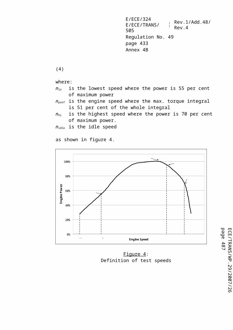
ECE/TR
AN
S/WP.29/2007/26
page 487
E/ECE/324E/ECE/TRANS/505 Rev.1/Add.48/Rev.4
Regulation No. 49page 433Annex 9A
parameter) for the purpose of detecting malfunctions and of minimizing the risk of indicating false malfunction. These devices are not defeat devices.
3.1.4. Access to the OBD system required for the inspection, diagnosis, servicing or repair of the engine shall be unrestricted and standardized. All emission related fault codes shall be consistent with those described in paragraph 6.8.5. of this annex.
3.2. OBD Stage 1 requirements
3.2.1. From the dates given in paragraph 5.4.2. of this Regulation, the OBD system of all diesel engines and of vehicles equipped with a diesel engine shall indicate the failure of an emission-related component or system when that failure results in an increase in emissions above the appropriate OBD thresholds given in the table in paragraph 5.4.4. of this Regulation.
3.2.2. In satisfying the Stage 1 requirements, the OBD system shall monitor for:
3.2.2.1. complete removal of a catalyst, where fitted in a separate housing, that may or may not be part of a deNOx system or particulate filter.
3.2.2.2. reduction in the efficiency of the deNOx system, where fitted, with respect to the emissions of NOx only.
3.2.2.3. reduction in the efficiency of the particulate filter, where fitted, with respect to the emissions of particulate only.
3.2.2.4. reduction in the efficiency of a combined deNOx-particulate filter system, where fitted, with respect to both the emissions of NOx and particulate.
3.2.3. Major functional failure
3.2.3.1. As an alternative to monitoring against the appropriate OBD threshold limits with respect to paragraphs 3.2.2.1. to 3.2.2.4., OBD systems of diesel engines may in accordance with paragraph 5.4.1.1. of this Regulation monitor for major functional failure of the following components:(a) a catalyst, where fitted as a separate unit, that may or may not be part of a deNOx
system or particulate filter;(b) a deNOx system, where fitted;(c) a particulate filter, where fitted;(d) a combined deNOx-particulate filter system.
3.2.3.2. In the case of an engine equipped with a deNOx system, examples of monitoring for major functional failure are for complete removal of the system or replacement of the system by a bogus system (both intentional major functional failure), lack of required

E/ECE/324E/ECE/TRANS/505 Rev.1/Add.48/Rev.4
Regulation No. 49page 434Annex 9A
reagent for a deNOx system, failure of any SCR electrical component, any electrical failure of a component (e.g. sensors and actuators, dosing control unit) of a deNOx system including, when applicable, the reagent heating system, failure of the reagent dosing system (e.g. missing air supply, clogged nozzle, dosing pump failure).
3.2.3.3. In the case of an engine equipped with a particulate filter, examples of monitoring for major functional failure are for major melting of the trap substrate or a clogged trap resulting in a differential pressure out of the range declared by the manufacturer, any electrical failure of a component (e.g. sensors and actuators, dosing control unit) of a particulate filter, any failure, when applicable, of a reagent dosing system (e.g. clogged nozzle, dosing pump failure).
3.2.4. Manufacturers may demonstrate to the Approval Authority that certain components or systems need not be monitored if, in the event of their total failure or removal, emissions do not exceed the applicable thresholds limits for OBD Stage 1 given in the table in paragraph 5.4.4. of this Regulation when measured over the cycles shown in paragraph 1.1. of Appendix 1 to this annex. This provision shall not apply to an exhaust gas recirculation (EGR) device, a deNOx system, a particulate filter or a combined deNOx-particulate filter system nor shall it apply to a component or system that is monitored for major functional failure.
3.3. OBD Stage 2 requirements
3.3.1. From the dates given in paragraph 5.4.2. of this Regulation the OBD system of all diesel or gas engines and of vehicles equipped with a diesel or a gas engine shall indicate the failure of an emission-related component or system of the engine system when that failure results in an increase in emissions above the appropriate OBD thresholds given in the table in paragraph 5.4.4. of this Regulation.
The OBD system shall consider the communication interface (hardware and messages) between the engine system electronic control unit(s) (EECU) and any other power train or vehicle control unit when the exchanged information has an influence on the correct functioning of the emission control. The OBD system shall diagnose the integrity of the connection between the EECU and the medium that provides the link with these other vehicle components (e.g. the communication bus).
3.3.2. In satisfying the Stage 2 requirements, the OBD system shall monitor for:
3.3.2.1. reduction in the efficiency of the catalyst, where fitted in a separate housing, that may or may not be part of a deNOx system or particulate filter.
3.3.2.2. reduction in the efficiency of the deNOx system, where fitted, with respect to the emissions of NOx only.

ECE/TR
AN
S/WP.29/2007/26
page 487
E/ECE/324E/ECE/TRANS/505 Rev.1/Add.48/Rev.4
Regulation No. 49page 435Annex 9A
3.3.2.3. reduction in the efficiency of the particulate filter, where fitted, with respect to the emissions of particulate only.
3.3.2.4. reduction in the efficiency of a combined deNOx-particulate filter system, where fitted, with respect to both the emissions of NOx and particulate.
3.3.2.5. the interface between the engine electronic control unit (EECU) and any other powertrain or vehicle electrical or electronic system (e.g. the transmission control unit (TECU)) for electrical disconnection.
3.3.3. Manufacturers may demonstrate to the Approval Authority that certain components or systems need not be monitored if, in the event of their total failure or removal, emissions do not exceed the applicable thresholds limits for OBD Stage 2 given in the table in paragraph 5.4.4. of this Regulation when measured over the cycles shown in paragraph 1.1. of Appendix 1 to this annex. This provision shall not apply to an exhaust gas recirculation (EGR) device, a deNOx system, a particulate filter or a combined deNOx-particulate filter system.
3.4. Stage 1 and Stage 2 requirements
3.4.1. In satisfying both the Stage 1 or Stage 2 requirements the OBD system shall monitor:
3.4.1.1. The fuel-injection system electronic, fuel quantity and timing actuator(s) for circuit continuity (i.e. open circuit or short circuit) and total functional failure.
3.4.1.2. All other engine or exhaust aftertreatment emission-related components or systems, which are connected to a computer, the failure of which would result in tailpipe emissions exceeding the OBD threshold limits given in the table in paragraph 5.4.4. of this Regulation. At a minimum, examples include the exhaust gas recirculation (EGR) system, systems or components for monitoring and control of air mass-flow, air volumetric flow (and temperature), boost pressure and inlet manifold pressure (and relevant sensors to enable these functions to be carried out), sensors and actuators of a deNOx system, sensors and actuators of an electronically activated active particulate filter.
3.4.1.3. Any other emission-related engine or exhaust aftertreatment component or system connected to an electronic control unit shall be monitored for electrical disconnection unless otherwise monitored.
3.4.1.4. In the case of engines equipped with an aftertreatment system using a consumable reagent, the OBD system shall monitor for:(a) lack of any required reagent;(b) the quality of the required reagent being within the specifications declared by the
manufacturer in Annex 1 to this Regulation;
E/ECE/324E/ECE/TRANS/505 Rev.1/Add.48/Rev.4
Regulation No. 49page 436Annex 9A
(c) reagent consumption and dosing activity;according to paragraph 5.5.4. of this Regulation.
3.5. OBD operation and temporary disablement of certain OBD monitoring capabilities
3.5.1. The OBD system shall be so designed, constructed and installed in a vehicle as to enable it to comply with the requirements of this annex during the conditions of use defined in paragraph 5.1.5.4. of this Regulation.
Outside these normal operating conditions the emission control system may show some degradation in OBD system performance such that the thresholds given in the table in paragraph 5.4.4. of this Regulation may be exceeded before the OBD system signals a failure to the driver of the vehicle.
The OBD system shall not be disabled unless one or more of the following conditions for disablement are met:
3.5.1.1. The affected OBD monitoring systems may be disabled if its ability to monitor is affected by low fuel levels. For this reason, disablement is permitted when the fuel tank level falls below 20 per cent of the nominal capacity of the fuel tank.
3.5.1.2. The affected OBD monitoring systems may be temporarily disabled during the operation of an auxiliary emission control strategy as described in paragraph 5.1.5.1. of this Regulation.
3.5.1.3. The affected OBD monitoring systems may be temporarily disabled when operational safety or limp-home strategies are activated.
3.5.1.4. For vehicles designed to accommodate the installation of power take-off units, disablement of affected OBD monitoring systems is permitted provided disablement takes place only when the power take-off unit is active and the vehicle is not being driven.
3.5.1.5. The affected OBD monitoring systems may be disabled temporarily during the periodic regeneration of an emission control system downstream of the engine (i.e. a particulate filter, deNOx system or combined deNOx-particulate filter).
3.5.1.6. The affected OBD monitoring systems may be disabled temporarily outside the conditions of use defined in paragraph 5.1.5.4. of this Regulation when this disablement can be justified by a limitation of the OBD monitoring (including modelling) capability.
3.5.2. The OBD monitoring system is not required to evaluate components during malfunction if such evaluation would result in a risk to safety or component failure.

ECE/TR
AN
S/WP.29/2007/26
page 487
E/ECE/324E/ECE/TRANS/505 Rev.1/Add.48/Rev.4
Regulation No. 49page 437Annex 9A
3.6. Activation of malfunction indicator (MI)
3.6.1. The OBD system shall incorporate a malfunction indicator readily visible to the vehicle operator. Except in the case of paragraph 3.6.2. of this annex, the MI (e.g. symbol or lamp) shall not be used for any purpose other than emission related malfunction except to indicate emergency start-up or limp-home routines to the driver. Safety related messages can be given the highest priority. The MI shall be visible in all reasonable lighting conditions. When activated, it shall display a symbol in conformity with ISO 2575 23/ (as a dashboard telltale lamp or a symbol on a dashboard display). A vehicle shall not be equipped with more than one general purpose MI for emission-related problems. Displaying separate specific information is permitted (e.g. such as information dealing with brake system, fasten seat belt, oil pressure, servicing requirements, or indicating the lack of necessary reagent for the deNOx system). The use of red for the MI is prohibited.
3.6.2. The MI may be used to indicate to the driver that an urgent service task needs to be carried out. Such an indication may also be accompanied by an appropriate message on a dashboard display that an urgent servicing requirement needs to be carried out.
3.6.3. For strategies requiring more than a preconditioning cycle for MI activation, the manufacturer shall provide data and/or an engineering evaluation which adequately demonstrates that the monitoring system is equally effective and timely in detecting component deterioration. Strategies requiring on average more than ten OBD or emission test cycles for MI activation are not accepted.
3.6.4. The MI shall also activate whenever the engine control enters a emission default mode of operation. The MI shall also activate if the OBD system is unable to fulfil the basic monitoring requirements specified in this Regulation.
3.6.5. Where reference is made to this paragraph, the MI shall be activated and, in addition, a distinct warning mode should also be activated, e.g. flashing MI or activation of a symbol in conformity with ISO 2575 24/ in addition to MI activation.
3.6.6. The MI shall activate when the vehicle's ignition is in the "key-on" position before engine starting or cranking and de-activate within 10 seconds after engine starting if no malfunction has previously been detected.
3.7. Fault code storage
The OBD system shall record fault code(s) indicating the status of the emission-control system. A fault code shall be stored for any detected and verified malfunction causing MI activation and shall identify the malfunctioning system or component as uniquely as
23/ Symbol numbers F01 or F22.24/ Symbol number F24.

E/ECE/324E/ECE/TRANS/505 Rev.1/Add.48/Rev.4
Regulation No. 49page 438Annex 9A
possible. A separate code should be stored indicating the expected MI activation status (e.g. MI commanded "ON", MI commanded "OFF").
Separate status codes shall be used to identify correctly functioning emission control systems and those emission control systems that need further engine operation to be fully evaluated. If the MI is activated due to malfunction or emission default modes of operation, a fault code shall be stored that identifies the likely area of malfunction. A fault code shall also be stored in the cases referred to in paragraphs 3.4.1.1. and 3.4.1.3. of this annex.
3.7.1. If monitoring has been disabled for 10 driving cycles due to the continued operation of the vehicle under conditions conforming to those specified in paragraph 3.5.1.2. of this annex, readiness for the subject monitoring system may be set to "ready" status without monitoring having been completed.
3.7.2. The hours run by the engine while the MI is activated shall be available upon request at any instant through the serial port on the standard link connector, according to the specifications given in paragraph 6.8. of this annex.
3.8. Extinguishing the MI
3.8.1. The MI may be de-activated after three subsequent sequential operating sequences or 24 engine running hours during which the monitoring system responsible for activating the MI ceases to detect the malfunction and if no other malfunction has been identified that would independently activate the MI.
3.8.2. In the case of MI activation due to lack of reagent for the deNOx system, or combined deNOx-particulate after-treatment device or use of a reagent outside the specifications declared by the manufacturer, the MI may be switched back to the previous state of activation after filling or replacement of the storage medium with a reagent having the correct specifications.
3.8.3. In the case of MI activation due to incorrect operation of the engine system with respect to NOx control measures, or incorrect reagent consumption and dosing activity, the MI may be switched back to the previous state of activation if the conditions given in paragraphs 5.5.3., 5.5.4 and 5.5.7. of this Regulation no longer apply.
3.9. Erasing a fault code
3.9.1 The OBD system may erase a fault code and the hours run by the engine and freeze-frame information if the same fault is not re-registered in at least 40 engine warm-up cycles or 100 engine running hours, whichever occurs first, with the exception of the cases referred to in paragraph 3.9.2.
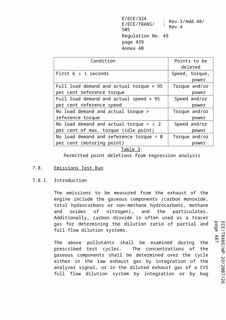
ECE/TR
AN
S/WP.29/2007/26
page 487
E/ECE/324E/ECE/TRANS/505 Rev.1/Add.48/Rev.4
Regulation No. 49page 439Annex 9A
3.9.2 From 9 November 2006 for new type approvals and from 1 October 2007 for all registrations, in the case of a non-erasable fault code being generated according to paragraph 5.5.3. or 5.5.4. of this Regulation, the OBD system shall retain a record of the fault code and the hours run by the engine during the MI activation for at least 400 days or 9,600 hours of engine operation.
Any such fault code and the corresponding hours run by the engine during MI activation shall not be erased through use of any external diagnostic or other tool as referred to in paragraph 6.8.3. of this annex.
4. REQUIREMENTS RELATING TO THE APPROVAL OF OBD SYSTEMS
4.1. For the purpose of approval, the OBD system shall be tested according to the procedures given in Appendix 1 to this annex.
An engine representative of its engine family (see paragraph 7. of this Regulation) shall be used for the OBD demonstration tests or the test report of the parent OBD system of the OBD engine family will be provided to the Approval Authority as an alternative to carrying out the OBD demonstration test.
4.1.1. In the case of OBD stage 1 referred to in paragraph 3.2., the OBD system shall:
4.1.1.1. indicate the failure of an emission-related component or system when that failure results in an increase in emissions above the OBD thresholds given in the table in paragraph 5.4.4. of this Regulation, or;
4.1.1.2. where appropriate, indicate any major functional failure of an exhaust aftertreatment system.
4.1.2. In the case of OBD stage 2 referred to in paragraph 3.3., the OBD system shall indicate the failure of an emission-related component or system when that failure results in an increase in emissions above the OBD thresholds given in the table in paragraph 5.4.4. of this Regulation.
4.1.3. In the case of both OBD 1 and OBD 2, the OBD system shall indicate the lack of any required reagent necessary for the operation of an exhaust aftertreatment system.
4.2. Installation requirements
4.2.1. The installation on the vehicle of an engine equipped with an OBD system shall comply with the following provisions of this annex with respect to the vehicle equipment:(a) the provisions of paragraphs 3.6.1., 3.6.2. and 3.6.5. concerning the MI and,
where appropriate, additional warning modes;

E/ECE/324E/ECE/TRANS/505 Rev.1/Add.48/Rev.4
Regulation No. 49page 440Annex 9A
(b) when applicable, the provisions of paragraph 6.8.3.1. concerning the use of an on-board diagnostic facility;
(c) the provisions of paragraph 6.8.6. concerning the connection interface.
4.3. Approval of an OBD system containing deficiencies
4.3.1. A manufacturer may request to the authority that an OBD system be accepted for approval even though the system contains one or more deficiencies such that the specific requirements of this annex are not fully met.
4.3.2. In considering the request, the authority shall determine whether compliance with the requirements of this annex is feasible or unreasonable.
The authority shall take into consideration data from the manufacturer that details such factors as, but not limited to, technical feasibility, lead time and production cycles including phase-in or phase-out of engines designs and programmed upgrades of computers, the extend to which the resultant OBD system will be effective in complying with the requirements of this Regulation and that the manufacturer has demonstrated an acceptable level of effort toward the requirements of this Regulation.
4.3.3. The authority will not accept any deficiency request that includes the complete lack of a required diagnostic monitor.
4.3.4. The authority shall not accept any deficiency request that does not respect the OBD threshold limits given in the table in paragraph 5.4.4. of this Regulation.
4.3.5. In determining the identified order of deficiencies, deficiencies relating to OBD Stage 1 in respect of paragraphs 3.2.2.1., 3.2.2.2., 3.2.2.3., 3.2.2.4. and 3.4.1.1. and OBD Stage 2 in respect of paragraphs 3.3.2.1., 3.3.2.2., 3.3.2.3., 3.3.2.4. and 3.4.1.1. of this annex shall be identified first.
4.3.6. Prior to or at the time of approval, no deficiency shall be granted in respect of the requirements of paragraph 3.2.3. and paragraph 6., except sub-paragraph 6.8.5. of this annex.
4.3.7. Deficiency period
4.3.7.1. A deficiency may be carried-over for a period of two years after the date of approval of the engine type or vehicle in respect of its engine type, unless it can be adequately demonstrated that substantial engine modifications and additional lead-time beyond two years would be necessary to correct the deficiency. In such a case, the deficiency may be carried-out for a period not exceeding three years.

ECE/TR
AN
S/WP.29/2007/26
page 487
E/ECE/324E/ECE/TRANS/505 Rev.1/Add.48/Rev.4
Regulation No. 49page 441Annex 9A
4.3.7.2. A manufacturer may request that the original Approval Authority grant a deficiency retrospectively when such a deficiency is discovered after the original approval. In this case, the deficiency may be carried-over for a period of two years after the date of notification to the Approval Authority unless it can be adequately demonstrated that substantial engine modifications and additional lead-time beyond two years would be necessary to correct the deficiency. In such a case, the deficiency may be carried-out for a period not exceeding three years.
4.3.7.3. The authority shall notify its decision in granting a deficiency request to all Contracting Parties.
5. ACCESS TO OBD INFORMATION
5.1. Replacement parts, diagnostic tools and test equipment
5.1.1. Applications for approval or amendment of an approval shall be accompanied by the relevant information concerning the OBD system. This relevant information shall enable manufacturers of replacement or retrofit components to make the parts they manufacture compatible with the OBD system with a view to fault-free operation assuring the vehicle user against malfunctions. Similarly, such relevant information shall enable the manufacturers of diagnostic tools and test equipment to make tools and equipment that provide for effective and accurate diagnosis of emission control systems.
5.1.2. Upon request, the approval authorities shall make Appendix 1 to Annex 2A, containing the relevant information on the OBD system as specified in the Appendix to Annex 9A to this Regulation, available to any interested components, diagnostic tools or test equipment manufacturer on a non-discriminatory basis.
5.1.2.1. In the case of replacement or service components, information can only be requested for such components that are subject to approval, or for components that form part of a system that is subject to approval.
5.1.2.2. The request for information shall identify the exact specification of the engine model type/engine model type within an engine family for which the information is required. It shall confirm that the information is required for the development of replacement or retrofit parts or components or diagnostic tools or test equipment.
5.2 Repair information
5.2.1. No later than three months after the manufacturer has provided any authorized dealer or repair shop within the Community with repair information, the manufacturer shall make that information (including all subsequent amendments and supplements) available upon reasonable and non-discriminatory payment.

E/ECE/324E/ECE/TRANS/505 Rev.1/Add.48/Rev.4
Regulation No. 49page 442Annex 9A
5.2.2. The manufacturer shall also make accessible, where appropriate upon payment the technical information required for the repair or maintenance of motor vehicles unless that information is covered by an intellectual property right or constitutes essential, secret know-how which is identified in an appropriate form; in such case, the necessary technical information shall not be withheld improperly.
Entitled to such information is any person engaged in commercially servicing or repairing, road-side rescuing, inspecting or testing of vehicles or in manufacturing or selling replacement or retro-fit components, diagnostic tools and test equipment.
5.2.3. In the event of failure to comply with these provisions the Approval Authority shall take appropriate measures to ensure that repair information is available, in accordance with the procedures laid down for approval and in-service surveys.
6. DIAGNOSTIC SIGNALS
6.1. Upon determination of the first malfunction of any component or system, "freeze-frame" engine conditions present at the time shall be stored in computer memory. Stored engine conditions shall include, but are not limited to calculated load value, engine speed, coolant temperature, intake manifold pressure (if available), and the fault code which caused the data to be stored. For freeze-frame storage, the manufacturer shall choose the most appropriate set of conditions facilitating effective repairs.
6.2. Only one frame of data is required. Manufacturers may choose to store additional frames provided that at least the required frame can be read by a generic scan tool meeting the specifications of paragraphs 6.8.3. and 6.8.4. If the fault code causing the conditions to be stored is erased in accordance with paragraph 3.9. of this annex, the stored engine conditions may also be erased.
6.3. If available, the following signals in addition to the required freeze-frame information shall be made available on demand through the serial port on the standardized data link connector, if the information is available to the on-board computer or can be determined using information available to the on-board computer: diagnostic trouble codes, engine coolant temperature, injection timing, intake air temperature, manifold air pressure, air flow rate, engine speed, pedal position sensor output value, calculated load value, vehicle speed and fuel pressure.
The signals shall be provided in standard units based on the specifications given in paragraph 6.8. Actual signals shall be clearly identified separately from default value or limp-home signals.
6.4. For all emission control systems for which specific on-board evaluation tests are conducted, separate status codes, or readiness codes, shall be stored in computer

ECE/TR
AN
S/WP.29/2007/26
page 487
E/ECE/324E/ECE/TRANS/505 Rev.1/Add.48/Rev.4
Regulation No. 49page 443Annex 9A
memory to identify correctly functioning emission control systems and those emission control systems which require further vehicle operation to complete a proper diagnostic evaluation. A readiness code need not be stored for those monitors that can be considered continuously operating monitors. Readiness codes should never be set to "not ready" status upon "key-on" or "key-off". The intentional setting of readiness codes to "not ready" status via service procedures shall apply to all such codes, rather than applying to individual codes.
6.5. The OBD requirements to which the vehicle is certified (i.e. stage 1 OBD or stage 2 OBD) and the major emission control systems monitored by the OBD system consistent with paragraph 6.8.4. shall be available through the serial data port on the standardized data link connector according to the specifications given in paragraph 6.8.
6.6. The software calibration identification number as declared in Annexes 1 and 2A to this Regulation shall be made available through the serial port of the standardized diagnostic connector. The software calibration identification number shall be provided in a standardized format.
6.7. The vehicle identification number (VIN) number shall be made available through the serial port of the standardized diagnostic connector. The VIN number shall be provided in a standardized format.
6.8. The emission control diagnostic system shall provide for standardized or unrestricted access and conform to either ISO 15765 or SAE J1939, as specified in the following paragraphs 25/.
6.8.1. The use of either ISO 15765 or SAE J1939 shall be consistent throughout paragraphs 6.8.2. to 6.8.5.
6.8.2. The on-board to off-board communications link shall conform to ISO 15765-4 or to the similar clauses within the SAE J1939 series of standards.
6.8.3. Test equipment and diagnostic tools needed to communicate with OBD systems shall meet or exceed the functional specification given in ISO 15031-4 or SAE J1939-73 paragraph 5.2.2.1.
6.8.3.1. The use of an on-board diagnostic facility such as a dashboard mounted video display device for enabling access to OBD information is permitted but this is in addition to enabling access to OBD information by means of the standard diagnostic connector.
25/ The use of the ISO single protocol standard (ISO/PAS 27145) developed for a world-wide global technical regulation on heavy-duty OBD will be considered to satisfy the appropriate requirements of paragraph 6.
E/ECE/324E/ECE/TRANS/505 Rev.1/Add.48/Rev.4
Regulation No. 49page 444Annex 9A
6.8.4. Diagnostic data, (as specified in this paragraph) and bi-directional control information shall be provided using the format and units described in ISO 15031-5 or SAE J1939-73 paragraph 5.2.2.1. and shall be available using a diagnostic tool meeting the requirements of ISO 15031-4 or SAE J1939-73 paragraph 5.2.2.1.
The manufacturer shall provide a national standardization body with emission-related diagnostic data, e.g. PID's, OBD monitor Id's, Test Id's not specified in ISO 15031-5 but related to this Regulation.
6.8.5. When a fault is registered, the manufacturer shall identify the fault using the most appropriate fault code consistent with those given in paragraph 6.3. of ISO 15031-6 relating to emission-related system diagnostic trouble codes. If such identification is not possible, the manufacturer may use diagnostic trouble codes according to paragraphs 5.3. and 5.6. of ISO 15031-6. The fault codes shall be fully accessible by standardized diagnostic equipment complying with the provisions of paragraph 6.8.3. of this annex.
The manufacturer shall provide a national standardization body with emission-related diagnostic data, e.g. PID's, OBD monitor Id's, Test Id's not specified in ISO 15031-5 but related to this Regulation.
As an alternative, the manufacturer may identify the fault using the most appropriate fault code consistent with those given in SAE J2012 or in SAE J1939-73.
6.8.6. The connection interface between the vehicle and the diagnostic tester shall be standardized and shall meet all the requirements of ISO 15031-3 or SAE J1939-13.
In the case of category N2, N3, M2, and M3 vehicles, as an alternative to the connector location described in the above standards and provided all other requirements of ISO 15031-3 are met, the connector may be located in a suitable position by the side of the driver's seat, including on the floor of the cabin. In this case the connector should be accessible by a person standing outside the vehicle and not restrict access to the driver's seat.
The installation position shall be subject to agreement of the Approval Authority such that it is readily accessible by service personnel but protected from accidental damage during normal conditions of use.

ECE/TR
AN
S/WP.29/2007/26
page 487
E/ECE/324E/ECE/TRANS/505 Rev.1/Add.48/Rev.4
Regulation No. 49page 445Annex 9A - Appendix
Annex 9A - Appendix
ON-BOARD DIAGNOSTIC (OBD) SYSTEM APPROVAL TESTS
1. INTRODUCTION
This appendix describes the procedure for checking the function of the on-board diagnostic (OBD) system installed on the engine by failure simulation of relevant emission-related systems in the engine management or emission control system. It also sets procedures for determining the durability of OBD systems.
1.1. Deteriorated components/systems
In order to demonstrate the efficient monitoring of an emission control system or component, the failure of which may result in tailpipe emissions exceeding the appropriate OBD threshold limits, the manufacturer shall make available the deteriorated components and/or electrical devices which would be used to simulate failures.
Such deteriorated components or devices shall not cause emissions to exceed the OBD threshold limits referred to in the table in paragraph 5.4.4. of this Regulation by more than 20 per cent.
In the case of approval of an OBD system according to paragraph 5.4.1. of this Regulation, the emissions shall be measured over the ESC test cycle (see Appendix 1 to Annex 4A to this Regulation). In the case of approval of an OBD system according to paragraph 5.4.2. of this Regulation, the emissions shall be measured over the ETC test cycle (see Appendix 2 to Annex 4A to this Regulation).
1.1.1. If it is determined that the installation of a deteriorated component or device on an engine means that a comparison with the OBD threshold limits is not possible (e.g. because the statistical conditions for validating the ETC test cycle are not met), the failure of that component or device may be considered as qualified upon the agreement of the Approval Authority based on technical argumentation provided by the manufacturer.
1.1.2. In the case that the installation of a deteriorated component or device on an engine means that the full load curve (as determined with a correctly operating engine) cannot (even partially) be attained during the test, the deteriorated component or device is considered as qualified upon the agreement of the Approval Authority based on technical argumentation provided by the manufacturer.
1.1.3. The use of deteriorated components or devices that cause engine emissions to exceed the OBD threshold limits referred to in the table in paragraph 5.4.4. of this Regulation
E/ECE/324E/ECE/TRANS/505 Rev.1/Add.48/Rev.4
Regulation No. 49page 446Annex 9A - Appendix
by no more than 20 per cent may not be required in some very specific cases (for example, if a limp home strategy is activated, if the engine cannot run any test, or in case of EGR sticking valves, etc). This exception shall be documented by the manufacturer. It is subject to the agreement of the Technical Service.
1.2. Test principle
When the engine is tested with the deteriorated component or device fitted, the OBD system is approved if the MI is activated. The OBD system is also approved if the MI is activated below the OBD threshold limits.
The use of deteriorated components or devices that cause the engine emissions to exceed the OBD threshold limits referred to in the table in paragraph 5.4.4. of this Regulation by no more than 20 per cent are not required in the specific case of the failure modes described in paragraphs 6.3.1.6. and 6.3.1.7. of this appendix and also with respect to monitoring for major functional failure.
1.2.1. The use of deteriorated components or devices that cause engine emissions to exceed the OBD threshold limits referred to in the table in paragraph 5.4.4. of this Regulation by no more than 20 per cent may not be required in some very specific cases (for example, if a limp home strategy is activated, if the engine cannot run any test, or in case of EGR sticking valves, etc). This exception shall be documented by the manufacturer. It is subject to the agreement of the Technical Service.
2. DESCRIPTION OF TEST
2.1. The testing of OBD systems consists of the following phases:(a) simulating the malfunction of a component of the engine management or emission
control system as described in paragraph 1.1. of this appendix;(b) preconditioning of the OBD system with a simulated malfunction over the
preconditioning cycle specified in paragraph 6.2.;(c) operating the engine with a simulated malfunction over the OBD test cycle
referred to in paragraph 6.1.;(d) determining whether the OBD system reacts to the simulated malfunction and
indicates malfunction in an appropriate manner.
2.1.1. Should the performance (e.g. power curve) of the engine be affected by the malfunction, the OBD test-cycle remains the shortened version of the ESC test-cycle used for the assessing the exhaust emissions of the engine without that malfunction.
2.2. Alternatively, at the request of the manufacturer, malfunction of one or more components may be electronically simulated according to the requirements of paragraph 6.

ECE/TR
AN
S/WP.29/2007/26
page 487
E/ECE/324E/ECE/TRANS/505 Rev.1/Add.48/Rev.4
Regulation No. 49page 447Annex 9A - Appendix
2.3. Manufacturers may request that monitoring take place outside the OBD test cycle referred to in paragraph 6.1. if it can be demonstrated to the authority that monitoring during conditions encountered during this OBD test cycle would impose restrictive monitoring conditions when the vehicle is used in service.
3. TEST ENGINE AND FUEL
3.1. Engine
The test engine shall comply with the specifications laid down in Annex 1 to this Regulation.
3.2. Fuel
The appropriate reference fuel as described in Annex 5 to this Regulation shall be used for testing.
4. TEST CONDITIONS
The test conditions shall satisfy the requirements of the emission test described in the present Regulation.
5. TEST EQUIPMENT
The engine dynamometer shall meet the requirements of Annex 4A to this Regulation.
6. OBD TEST CYCLE
6.1. The OBD test cycle is a single shortened ESC test cycle. The individual modes shall be performed in the same order as the ESC test cycle, as defined in paragraph 2.7.1. of Appendix 1 to Annex 4A to this Regulation .
The engine shall be operated for a maximum of 60 seconds in each mode, completing engine speed and load changes in the first 20 seconds. The specified speed shall be held to within 50 min-1 and the specified torque shall be held to within 2 per cent of the maximum torque at each speed.
Exhaust emissions are not required to be measured during the OBD test cycle.
6.2. Preconditioning cycle
6.2.1. After introduction of one of the failure modes given in paragraph 6.3., the engine and its OBD system shall be preconditioned by performing a preconditioning cycle.

E/ECE/324E/ECE/TRANS/505 Rev.1/Add.48/Rev.4
Regulation No. 49page 448Annex 9A - Appendix
6.2.2. At the request of the manufacturer and with the agreement of the Approval Authority, an alternative number of a maximum of nine consecutive OBD test cycles may be used.
6.3. OBD system test
6.3.1. Diesel engines and vehicles equipped with a diesel engine
6.3.1.1. After preconditioning according to paragraph 6.2., the test engine is operated over the OBD test cycle described in paragraph 6.1. of this appendix. The MI shall activate before the end of this test under any of the conditions given in paragraphs 6.3.1.2. to 6.3.1.7. The Technical Service may substitute those conditions by others in accordance with paragraph 6.3.1.7. For the purposes of approval, the total number of failures subject to testing, in the case of different systems or components, shall not exceed four.
If the test is being carried out to type-approve an OBD-engine family consisting of engines that do not belong to the same engine family, the type Approval Authority will increase the number of failures subject to testing up to a maximum of four times the number of engine families present in the OBD-engine family. The Approval Authority may decide to curtail the test at any time before this maximum number of failure tests has been reached.
6.3.1.2. Where fitted in a separate housing that may or may not be part of a deNOx system or diesel particulate filter, replacement of any catalyst with a deteriorated or defective catalyst or electronic simulation of such a failure.
6.3.1.3. Where fitted, replacement of a deNOx system (including any sensors that are an integral part of the system) with a deteriorated or defective deNOx system or electronic simulation of a deteriorated or defective deNOx system that results in emissions exceeding the OBD NOx threshold limit referred to in the table given in paragraph 5.4.4. of this Regulation.
In the case that the engine is being approved according to paragraph 5.4.1. of this Regulation in relation to monitoring for major functional failure, the test of the deNOx system shall determine that the MI illuminates under any of the following conditions:(a) complete removal of the system or replacement of the system by a bogus system;(b) lack of any required reagent for a deNOx system;(c) any electrical failure of a component (e.g. sensors and actuators, dosing control
unit) of a deNOx system, including, when applicable, the reagent heating system;(d) failure of a reagent dosing system (e.g. missing air supply, clogged nozzle, dosing
pump failure) of a deNOx system;(e) major breakdown of the system.
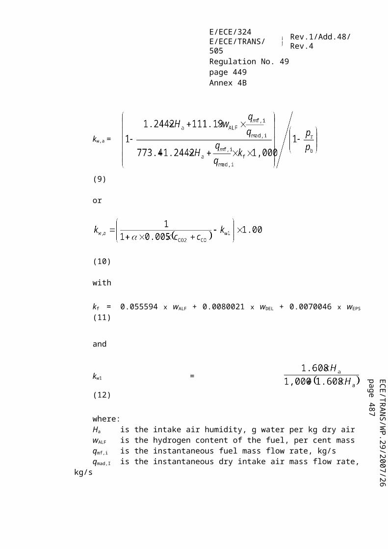
ECE/TR
AN
S/WP.29/2007/26
page 487
E/ECE/324E/ECE/TRANS/505 Rev.1/Add.48/Rev.4
Regulation No. 49page 449Annex 9A - Appendix
6.3.1.4. Where fitted, total removal of the particulate filter or replacement of the particulate filter with a defective particulate filter that results in emissions exceeding the OBD particulate threshold limit given in the table in paragraph 5.4.4. of this Regulation.
In the case that the engine is being approved according to paragraph 5.4.1. of this Regulation in relation to monitoring for major functional failure, the test of the particulate filter shall determine that the MI illuminates under any of the following conditions:(a) complete removal of the particulate filter or replacement of the system by a bogus
system;(b) major melting of the particulate filter substrate;(c) major cracking of the particulate filter substrate;(d) any electrical failure of a component (e.g. sensors and actuators, dosing control
unit) of a particulate filter;(e) failure, when applicable, of the reagent dosing system (e.g. clogged nozzle, dosing
pump failure) of a particulate filter;(f) a clogged particulate filter resulting in a differential pressure out of the range
declared by the manufacturer.
6.3.1.5. Where fitted, replacement of a combined deNOx-particulate filter system (including any sensors that are an integral part of the device) with a deteriorated or defective system or electronic simulation of a deteriorated or defective system that results in emissions exceeding the OBD NOx and particulate threshold limits given in the table in paragraph 5.4.4. of this Regulation.
In the case that the engine is being approved according to paragraph 5.4.1. of this Regulation in relation to monitoring for major functional failure, the test of the combined deNOx-particulate filter system shall determine that the MI illuminates under any of the following conditions:(a) complete removal of the system or replacement of the system by a bogus system;(b) lack of any required reagent for a combined deNOx-particulate filter system;(c) any electrical failure of a component (e.g. sensors and actuators, dosing control
unit) of a combined deNOx-particulate filter system, including, when applicable, the reagent heating system;
(d) failure of a reagent dosing system (e.g. missing air supply, clogged nozzle, dosing pump failure) of a combined deNOx-particulate filter system;
(e) major breakdown of a NOx trap system;(f) major melting of the particulate filter substrate;(g) major cracking of the particulate filter substrate;(h) a clogged particulate filter resulting in a differential pressure out of the range
declared by the manufacturer.

E/ECE/324E/ECE/TRANS/505 Rev.1/Add.48/Rev.4
Regulation No. 49page 450Annex 9A - Appendix
6.3.1.6. Disconnection of any fuelling system electronic fuel quantity and timing actuator that results in emissions exceeding any of the OBD thresholds referred to in the table given in paragraph 5.4.4. of this Regulation.
6.3.1.7. Disconnection of any other emission-related engine component connected to a computer that results in emissions exceeding any of the thresholds referred to in the table given in paragraph 5.4.4. of this Regulation.
6.3.1.8. In demonstrating compliance with the requirements of paragraphs 6.3.1.6. and 6.3.1.7. and with the agreement of the Approval Authority, the manufacturer may take appropriate steps to demonstrate that the OBD system will indicate a fault when disconnection occurs.

ECE/TR
AN
S/WP.29/2007/26
page 487
E/ECE/324E/ECE/TRANS/505 Rev.1/Add.48/Rev.4
Regulation No. 49page 451Annex 9B
Annex 9B
TECHNICAL REQUIREMENTS FOR ON-BOARD DIAGNOSTIC SYSTEMS (OBD) FOR DIESEL ENGINES OF ROAD VEHICLES (WWH-OBD, gtr No. 5)
1. APPLICABILITY
This annex is not applicable, for the time being, for the purpose of type approval according to this Regulation. It will be made applicable in the future.
2. Reserved 26/.
3. DEFINITIONS
3.1. "Alert system" means a system on-board the vehicle which informs the driver of the vehicle or any other interested party that the OBD system has detected a malfunction.
3.2. "Approval authority" means the authority that grants the compliance approval of an OBD system considered by this annex. Per extension, it means also the Technical Service that has been accredited to evaluate the technical compliance of the OBD system.
3.3. "Calibration verification number" means the number that is calculated and reported by the engine system to validate the calibration/software integrity.
3.4. "Component monitoring" means the monitoring of input components for electrical circuit failures and rationality failures and monitoring of output components for electrical circuit failures and functionality failures. It refers to components that are electrically connected to the controller(s) of the engine system.
3.5. "Confirmed and active DTC" means a DTC that is stored during the time the OBD system concludes that a malfunction exists.
3.6. "Continuous-MI" means the malfunction indicator showing a steady indication at all times while the key is in the on (run) position with the engine running (ignition on - engine on).
3.7. "Deficiency" means an OBD monitoring strategy or other OBD feature that does not meet all the detailed requirements of this annex.
26/ The numbering of this annex is consistent with the numbering of gtr No. 5 on WWH-OBD. However, some paragraphs of the WWH-OBD gtr are not needed in this annex.

E/ECE/324E/ECE/TRANS/505 Rev.1/Add.48/Rev.4
Regulation No. 49page 452Annex 9B
3.8. "Diagnostic trouble code (DTC)" means a numeric or alphanumeric identifier which identifies or labels a malfunction.
3.9. "Electrical circuit failure" means a malfunction (e.g. open circuit or short circuit) that leads to the measured signal (i.e. voltages, currents, frequencies, etc.) being outside the range where the transfer function of the sensor is designed to operate.
3.10. "Emission OBD family" means a manufacturer's grouping of engine systems having common methods of monitoring/diagnosing emission-related malfunctions.
3.11. "Emission threshold monitoring" means monitoring of a malfunction that leads to an excess of the OTLs. It consists of:(a) direct emissions measurement via a tailpipe emissions sensor(s) and a model to
correlate the direct emissions to test-cycle specific emissions; and/or(b) indication of an emissions increase via correlation of computer input/output
information to test-cycle specific emissions.
3.12. "Engine system" means the engine as it would be configured when tested for its exhaust emissions on a approval test-bed, including:(a) the engine's electronic management controller(s);(b) the exhaust after-treatment system(s);(c) any emission-related component of the engine or the exhaust system which
supplies input to, or receives output from, the engine's electronic management controller(s); and
(d) the communication interface (hardware and messages) between the engine's electronic management controller(s) and any other power train or vehicle control unit if the exchanged information has an influence on the control of emissions.
3.13. "Functionality failure" means a malfunction where an output component does not respond to a computer command in the expected way.
3.14. "Malfunction emission control strategy (MECS)" means a strategy within the engine system that is activated as a result of an emission-related malfunction.
3.15. "Malfunction indicator (MI)" is an indicator which clearly informs the driver of the vehicle in the event of a malfunction. The MI is part of the alert system (see "continuous-MI", "on-demand-MI", and "short-MI").
3.16. "Malfunction" means a failure or deterioration of an engine system, including the OBD system, that may lead either to an increase in any of the regulated pollutants emitted by the engine system or to a reduction in the effectiveness of the OBD system.

ECE/TR
AN
S/WP.29/2007/26
page 487
E/ECE/324E/ECE/TRANS/505 Rev.1/Add.48/Rev.4
Regulation No. 49page 453Annex 9B
3.17. "MI status" means the command status of the MI, being either continuous-MI, Short-MI, on-demand-MI, or off.
3.18. "Monitoring" (see "emission threshold monitoring", "performance monitoring", and "total functional failure monitoring")
3.19. "OBD test-cycle" means the cycle over which an engine system is operated on an engine test-bed to evaluate the response of an OBD system to the presence of a qualified deteriorated component.
3.20. "OBD-parent engine system" means an engine system that has been selected from an emission-OBD family for which most of its OBD elements of design are representative of that family.
3.21. "On-board diagnostic system (OBD)" means a system on-board a vehicle or engine which has the capability:(a) of detecting malfunctions, affecting the emission performance of the engine
system;(b) of indicating their occurrence by means of an alert system;(c) of identifying the likely area of the malfunctions by means of information stored
in computer memory and/or communicating that information off-board.
3.22. "On-demand-MI" means the malfunction indicator showing a steady indication in response to a manual demand from the driving position when the key is in the on (run) position with the engine off (ignition on - engine off).
3.23. "Operating sequence" means a sequence consisting of an engine start-up, an operating period, an engine shut-off, and the time until the next start-up, where a specific OBD monitor runs to completion and a malfunction would be detected if present.
3.24. "Pending DTC" means a DTC that is stored by the OBD system because a monitor has detected a situation where a malfunction may be present during the current or last completed operating sequence.
3.25. "Performance monitoring" means malfunction monitoring that consists of functionality checks and monitoring parameters that are not correlated to emission thresholds. Such monitoring is typically done on components or systems to verify that they are operating within the proper range (e.g. differential pressure in case of a DPF).
3.26. "Potential DTC" means a DTC that is stored by the OBD system because a monitor has detected a situation where a malfunction may be present but requires further

E/ECE/324E/ECE/TRANS/505 Rev.1/Add.48/Rev.4
Regulation No. 49page 454Annex 9B
evaluation to be confirmed. A potential DTC is a pending DTC which is not a confirmed and active DTC.
3.27. "Previously active DTC" means a formerly confirmed and active DTC that remains stored after the OBD system has concluded that the malfunction that caused the DTC is no longer present.
3.28. "Qualified deteriorated component or system (QDC)"means a component or system that has been intentionally deteriorated (e.g. accelerated aging) and/or manipulated in a controlled manner and which has been accepted by the authorities according to the provisions set in this annex.
3.29. "Rationality failure" means a malfunction where the signal from an individual sensor or component is at variance with that expected when assessed against signals available from other sensors or components within the control system. Rationality failures include malfunctions that lead to the measured signal (i.e. voltages, currents, frequencies, etc.) being inside the range where the transfer function of the sensor is designed to operate.
3.30. "Readiness" means a status indicating whether a monitor or a group of monitors have run since the last erasing by request of an external OBD scan-tool.
3.31. "Scan-tool" means an external test equipment used for standardised off-board communication with the OBD system in accordance with the requirements of this annex.
3.32. "Short-MI" means the malfunction indicator showing a steady indication from the time the key is moved to on (run) position and the engine is started (ignition on - engine on) and extinguishing after 15 seconds or the key is moved to off, whichever occurs first.
3.33. "Software calibration identification" means a series of alphanumeric characters that identifies the emission-related calibration / software version(s) installed in the engine system.
3.34. "Total functional failure monitoring" means monitoring a malfunction which is leading to a complete loss of the desired function of a system.
3.35. "Warm-up cycle" means sufficient engine operation such that the coolant temperature has risen by at least 295 K (22 °C / 40 °F) from engine starting and reaches a minimum temperature of 333 K (60 °C / 140 °F) 27/.
27/ This definition does not imply that a temperature sensor is necessary to measure the coolant temperature.

ECE/TR
AN
S/WP.29/2007/26
page 487
E/ECE/324E/ECE/TRANS/505 Rev.1/Add.48/Rev.4
Regulation No. 49page 455Annex 9B
3.36. Abbreviations
CV Crankcase VentilationDOC Diesel Oxidation CatalystDPF Diesel Particulate Filter or Particulate Trap including catalyzed DPFs and
Continuously Regenerating Traps (CRT)DTC Diagnostic trouble codeEGR Exhaust Gas RecirculationHC HydrocarbonLNT Lean NOx Trap (or NOx absorber)MECS Malfunction Emission Control StrategyNOx Oxides of NitrogenOTL OBD Threshold LimitPM Particulate MatterSCR Selective Catalytic ReductionSW Screen WipersTFF Total Functional Failure monitoringVGT Variable Geometry TurbochargerVVT Variable Valve Timing
4. GENERAL REQUIREMENTS
In the context of this annex, the OBD system shall have the capability of detecting In malfunctions, of indicating their occurrence by means of a malfunction indicator, of identifying the likely area of the malfunctions by means of information stored in computer memory, and communicating that information off-board.
The OBD system shall be designed and constructed so as to enable it to identify types of malfunctions over the complete life of the vehicle/engine. In achieving this objective, the Approval Authority will recognize that engines which have been used in excess of their regulatory useful life may show some deterioration in OBD system performance and sensitivity such that the OBD thresholds may be exceeded before the OBD system signals a malfunction to the driver of the vehicle.
The above paragraph does not extend the engine manufacturer's compliance liability for an engine beyond its regulated useful life (i.e. the time or distance period during which emission standards or emission limits continue to apply).

E/ECE/324E/ECE/TRANS/505 Rev.1/Add.48/Rev.4
Regulation No. 49page 456Annex 9B
4.1. Application for approval of an OBD system
4.1.1. Primary approval
The manufacturer of an engine system may apply for the approval of its OBD system in one of the three following manners:
(a) The manufacturer of an engine system applies for the approval of an individual OBD system by demonstrating that OBD system complies with all the provisions of this annex.
(b) The manufacturer of an engine system applies for the approval of an emission-OBD family by demonstrating that the OBD-parent engine system of the family complies with all the provisions of this annex.
The manufacturer of an engine system applies for the approval of an OBD system by demonstrating that OBD system meets the criteria for belonging to an emission-OBD family that has already been certified.
4.1.2. Extension / Modification of an existing certificate
4.1.2.1. Extension to include a new engine system into an emission-OBD family
At the request of the manufacturer and upon approval of the Approval Authority, a new engine system may be included as a member of a certified emission-OBD family if all the engine systems within the so-extended emission-OBD family still have common methods of monitoring / diagnosing emission-related malfunctions.
If all OBD elements of design of the OBD-parent engine system are representative of those of the new engine system, then the OBD-parent engine system shall remain unchanged and the manufacturer shall modify the documentation package according to paragraph 8 of this annex.
If the new engine system contains elements of design that are not represented by the OBD-parent engine system but itself would represent the whole family, then the new engine system shall become the new OBD-parent engine system. In this case the new OBD elements of design shall be demonstrated to comply with the provisions of this annex, and the documentation package shall be modified according to paragraph 8. of this annex.
4.1.2.2. Extension to address a design change that affects the OBD system
At the request of the manufacturer and upon approval of the Approval Authority, an extension of an existing certificate may be granted in the case of a design change of
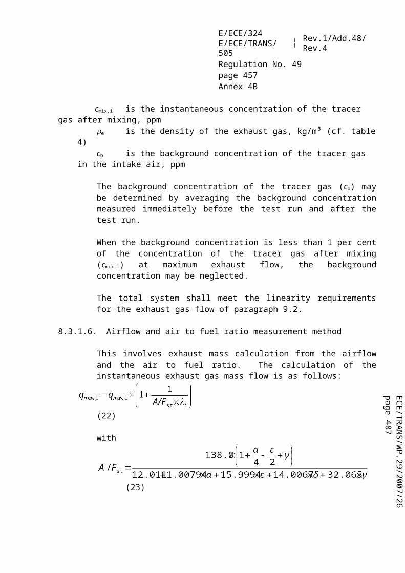
ECE/TR
AN
S/WP.29/2007/26
page 487
E/ECE/324E/ECE/TRANS/505 Rev.1/Add.48/Rev.4
Regulation No. 49page 457Annex 9B
the OBD system if the manufacturer demonstrates that the design changes comply with the provisions of this annex.
The documentation package shall be modified according to paragraph 8. of this annex.
If the existing certificate applies to an emission-OBD family, the manufacturer shall justify to the Approval Authority that the methods of monitoring/diagnosing emission-related malfunctions are still common within the family and that the OBD-parent engine system remains representative of the family.
4.1.2.3. Certificate modification to address a malfunction reclassification
This paragraph applies when, following a request by the authority that granted the approval, or at its own initiative, the manufacturer applies for a modification of an existing certificate in order to reclassify one or several malfunctions.
The compliance of the new classification shall then be demonstrated according to the provisions of this annex and the documentation package shall be modified according to paragraph 8 of this annex.
4.2. Monitoring requirements
All emission-related components and systems included in an engine system shall be monitored by the OBD system in accordance with the requirements set in appendix 3. However, the OBD system is not required to use a unique monitor to detect each malfunction referred to in appendix 3.
The OBD system shall also monitor its own components.
The items of appendix 3 list the systems or components required to be monitored by the OBD system and describes the types of monitoring expected for each of these components or systems (i.e. emission threshold monitoring, performance monitoring, total functional failure monitoring, or component monitoring).
The manufacturer can decide to monitor additional systems and components.
4.2.1. Selection of the monitoring technique
Approval authorities may approve a manufacturer's use of another type of monitoring technique than the one mentioned in Appendix 3. The chosen type of monitoring shall be shown by the manufacturer, to be robust, timely and efficient (i.e. through either technical considerations, test results, previous agreements, etc.).
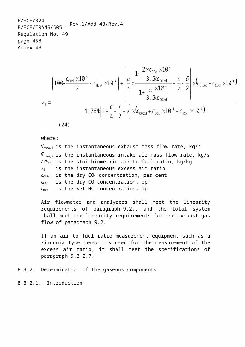
E/ECE/324E/ECE/TRANS/505 Rev.1/Add.48/Rev.4
Regulation No. 49page 458Annex 9B
In case a system and / or component is not covered by Appendix 3 the manufacturer shall submit for approval to the Approval Authority an approach to monitoring. The Approval Authority will approve the chosen type of monitoring and monitoring technique (i.e. emission threshold monitoring, performance monitoring, total functional failure monitoring, or component monitoring) if it has been shown by the manufacturer, by reference to those detailed in Appendix 3, to be robust, timely and efficient (i.e. through either technical considerations, test results, previous agreements, etc.).
4.2.1.1. Correlation to actual emissions
In the case of emission threshold monitoring, a correlation to test-cycle specific emissions shall be required. This correlation would typically be demonstrated on a test engine in a laboratory setting.
In all other monitoring cases (i.e. performance monitoring, total functional failure monitoring, or component monitoring), no correlation to actual emissions is necessary. However, the Approval Authority may request test data to verify the classification of the malfunction effects as described in paragraph 6.2. of this annex.
Examples:
An electrical malfunction may not require a correlation because this is a yes/no malfunction. A DPF malfunction monitored via delta pressure may not require a correlation because it anticipates a malfunction.
If the manufacturer demonstrates, according to the demonstration requirements of this annex, that emissions would not exceed the OBD threshold limits upon total failure or removal of a component or system, a performance monitoring of this component or system shall be accepted.
When a tailpipe emission sensor is used for monitoring the emissions of a specific pollutant all other monitors may be exempted from further correlation to the actual emissions of that pollutant. Nevertheless, such exemption shall not preclude the need to include these monitors, using other monitoring techniques, as part of the OBD system as the monitors are still needed for the purpose of malfunction isolation.
A malfunction shall always be classified according to paragraph 4.5. based on its impact on emissions, regardless of the type of monitoring used to detect the malfunction.

ECE/TR
AN
S/WP.29/2007/26
page 487
E/ECE/324E/ECE/TRANS/505 Rev.1/Add.48/Rev.4
Regulation No. 49page 459Annex 9B
4.2.2. Component monitoring (input/output components/systems)
In the case of input components that belong to the engine system, the OBD system shall at a minimum detect electrical circuit failures and, where feasible, rationality failures.
The rationality failure diagnostics shall then verify that a sensor output is neither inappropriately high nor inappropriately low (i.e. there shall be "two-sided" diagnostics).
To the extent feasible, and with the agreement of the Approval Authority, the OBD system shall detect separately, rationality failures (e.g. inappropriately high and inappropriately low), and electrical circuit failures (e.g. out-of-range high and out-of-range low). Additionally, unique DTCs for each distinct malfunction (e.g. out-of-range low, out-of-range high and rationality failure) shall be stored.
In the case of output components that belong to the engine system, the OBD system shall at a minimum detect electrical circuit failures, and, where feasible, if the proper functional response to computer commands does not occur.
To the extent feasible, and with the agreement of the Approval Authority, the OBD system shall detect separately functionality failures, electrical circuit failures (e.g. out-of-range high and out-of-range low) and store unique DTCs for each distinct malfunction (e.g. out-of-range low, out-of-range high, functionality failure).
The OBD system shall also perform rationality monitoring on the information coming from or provided to components that do not belong to the engine system when this information compromises the emission control system and/or the engine system for proper performance.
4.2.2.1. Exception to component monitoring
Monitoring of electrical circuit failures, and to the extent feasible, functionality, and rationality failures of the engine system shall not be required if all the following conditions are met:(a) the failure results in an emission increase of any pollutant of less than 50 per
cent of the regulated emission limit, and
(b) the failure does not cause any emission to exceed the regulated emission limit 28/, and
(c) the failure does not affect a component or system enabling the proper
28/ The measured value shall be considered taking into account the relevant precision tolerance of the test-cell system and the increased variability in the test results due to the malfunction.

E/ECE/324E/ECE/TRANS/505 Rev.1/Add.48/Rev.4
Regulation No. 49page 460Annex 9B
performance of the OBD system.
Determination of the emissions impact shall be performed on a stabilized engine system in an engine dynamometer test cell, according to the demonstration procedures of this annex.
4.2.3. Monitoring frequency
Monitors shall run continuously, at any time where the monitoring conditions are fulfilled, or once per operating sequence (e.g. for monitors that lead to an increase of emission when it runs).
When a monitor does not run continuously, the manufacturer shall clearly inform the Approval Authority and describe the conditions under which the monitor runs.
The monitors shall run during the applicable OBD test-cycle as specified in paragraph 7.2.2.
A monitor shall be regarded as running continuously, if it runs at a rate not less than once per second. If a computer input or output component is sampled less frequently than one sample per second for engine control purpose, a monitor shall also regarded as running continuously, if the signal of the component is evaluated each time sampling occurs.
For components or systems monitored continuously, it is not required to activate an output component/system for the sole purpose of monitoring that output component/system.
4.3. Requirements for recording OBD information
When a malfunction has been detected but is not yet confirmed, the possible malfunction shall be considered as a "Potential DTC" and accordingly a "Pending DTC" status shall be recorded. A "Potential DTC" shall not lead to an activation of the alert system according to paragraph 4.6.
Within the first operating sequence, a malfunction may be directly considered "confirmed and active" without having been considered a "potential DTC". It shall be given the "Pending DTC" and a "confirmed and active DTC" status.
In case a malfunction with the previously active status occurs again, that malfunction may at the choice of manufacturer be directly given the "Pending DTC " and "confirmed and active DTC" status. Without having been given the "potential DTC" status. If that malfunction is given the potential status, it shall also keep the previously active status during the time it is not yet confirmed or active.

ECE/TR
AN
S/WP.29/2007/26
page 487
E/ECE/324E/ECE/TRANS/505 Rev.1/Add.48/Rev.4
Regulation No. 49page 461Annex 9B
The monitoring system shall conclude whether a malfunction is present before the end of the next operating sequence following its first detection. At this time, a "confirmed and active" DTC shall be stored and the alert system be activated according to paragraph 4.6.
In case of a recoverable MECS (i.e. the operation automatically returns to normal and the MECS is de-activated at the next engine ON), a "confirmed and active" DTC need not be stored unless the MECS is again activated before the end of the next operating sequence. In case of a non-recoverable MECS, a "confirmed and active" DTC shall be stored as soon as the MECS is activated.
In some specific cases where monitors need more than two operating sequences to accurately detect and confirm a malfunction (e.g. monitors using statistical models or with respect to fluid consumption on the vehicle), the Approval Authority may permit the use of more than two operating sequences for monitoring provided the manufacturer justifies the need for the longer period (e.g. by technical rationale, experimental results, in house experience, etc.).
When a confirmed and active malfunction is no longer detected by the system during a complete operating sequence, it shall be given the previously active status by the start of the next operating sequence and keep that status until this malfunction is erased by a scan tool or erased from the computer memory according to paragraph 4.4.
Note: The requirements prescribed in this paragraph are illustrated in Appendix 2 .
4.4. Requirements for erasing OBD information
DTC and the applicable information (inclusive the associated freeze frame) shall not be erased by the OBD system itself from the computer memory until that DTC has been in the previously active status for at least 40 warm-up cycles or 200 engine operating hours, whichever occurs first. The OBD system shall erase all the DTCs and the applicable information (inclusive the associated freeze frame) upon request of a scan tool or a maintenance tool.
4.5. Requirements for malfunction classification
Malfunction classification specifies the class to which a malfunction is assigned when such a malfunction is detected, according to the requirements of paragraph 4.2. of this annex.
A malfunction shall be assigned to one class for the actual life of the vehicle unless the authority that granted the certificate or the manufacturer determines that

E/ECE/324E/ECE/TRANS/505 Rev.1/Add.48/Rev.4
Regulation No. 49page 462Annex 9B
reclassification of that malfunction is necessary.
If a malfunction would result in a different classification for different regulated pollutant emissions or for its impact on other monitoring capability, the malfunction shall be assigned to the class that takes precedence in the discriminatory display strategy.
If an MECS is activated as a result of the detection of a malfunction, this malfunction shall be classified based on either the emission impact of the activated MECS or its impact on other monitoring capability. The malfunction shall then assigned to the class that takes precedence in the discriminatory display strategy.
4.5.1. Class A malfunction
A malfunction shall be identified as Class A when the relevant OBD threshold limits (OTLs) are assumed to be exceeded.
It is accepted that the emissions may not be above the OTLs when this class of malfunction occurs.
4.5.2. Class B1 malfunction
A malfunction shall be identified as Class B1 where circumstances exist that have the potential to lead to emissions being above the OTLs but for which the exact influence on emission cannot be estimated and thus the actual emissions according to circumstances may be above or below the OTLs.
Examples of Class B1 malfunctions may include malfunctions detected by monitors that infer emission levels based on readings of sensors or restricted monitoring capability.
Class B1 malfunctions shall include malfunctions that restrict the ability of the OBD system to carry out monitoring of Class A or B1 malfunctions.
4.5.3. Class B2 malfunction
A malfunction shall be identified as Class B2 when circumstances exist that are assumed to influence emissions but not to a level that exceeds the OTL.
Malfunctions that restrict the ability of the OBD system to carry out monitoring of Class B2 malfunctions of shall be classified into Class B1 or B2.
4.5.4. Class C malfunction

ECE/TR
AN
S/WP.29/2007/26
page 487
E/ECE/324E/ECE/TRANS/505 Rev.1/Add.48/Rev.4
Regulation No. 49page 463Annex 9B
A malfunction shall be identified as Class C when circumstances exist that, if monitored, are assumed to influence emissions but to a level that would not exceed the regulated emission limits.
Malfunctions that restrict the ability of the OBD system to carry out monitoring of Class C malfunctions shall be classified into Class B1 or B2.
4.6. Alert system
The failure of a component of the alert system shall not cause the OBD system to stop functioning.
4.6.1. MI specification
The malfunction indicator shall be perceptible by the driver from the driver's seat position under all lighting conditions. The malfunction indicator shall comprise a yellow (as defined in Annex 5 to UNECE Regulation No. 7) or amber (as defined in Annex 5 to UNECE Regulation No. 6) warning signal identified by the F01 symbol in accordance with ISO Standard 2575:2004.
4.6.2. MI illumination schemes
Depending on the malfunction(s) detected by the OBD system, the MI shall be illuminated according to one of the activation modes described in the following table:
Activation mode 1 Activation mode 2 Activation mode 3 Activation mode 4
Conditions of activation No malfunction Class C
malfunction
Class B malfunction and
B1 counters < 200 h
Class A malfunction or B1
counter > 200 h
Key on engine on No display Discriminatory
display strategyDiscriminatory display strategy
Discriminatory display strategy
Key on engine off
Harmonized display strategy
Harmonized display strategy
Harmonized display strategy
Harmonized display strategy
The display strategy requires the MI to be activated according to the class in which a malfunction has been classified. This strategy shall be locked by software coding that shall not be routinely available via the scan tool.
The MI activation strategy at key on, engine off is described in paragraph 4.6.4.
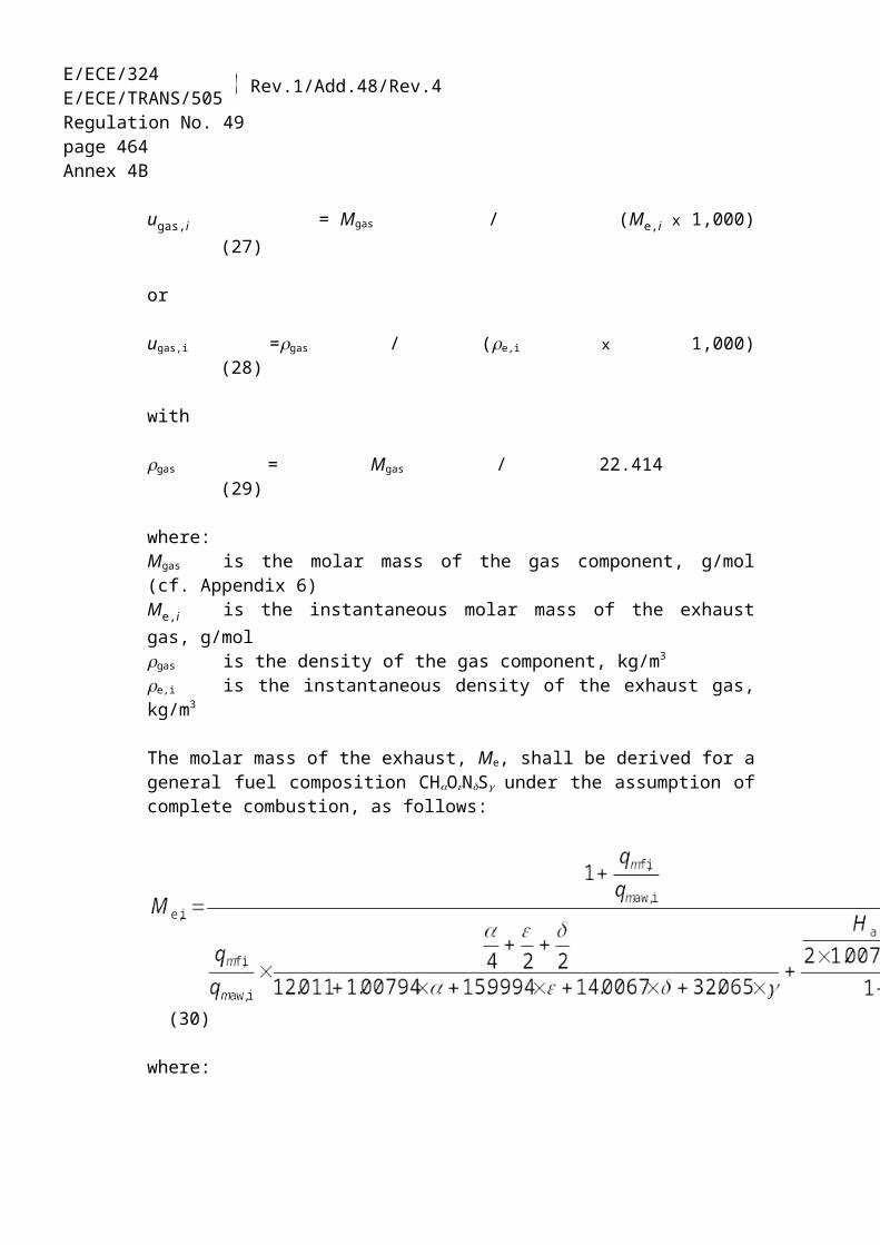
E/ECE/324E/ECE/TRANS/505 Rev.1/Add.48/Rev.4
Regulation No. 49page 464Annex 9B
Figures B1 and B2 illustrate the prescribed activation strategies at key on, engine on or off.
--------------------------
Figure B1Bulb test and readiness indication
ENGINE ON ENGINE OFF
a) MI (bulb) functioning, no malfunction to report, and the readiness of all monitored components "complete".
b) MI (bulb) functioning, no malfunction to report, and at least one component with readiness "not complete".
c) MI (bulb) non operational
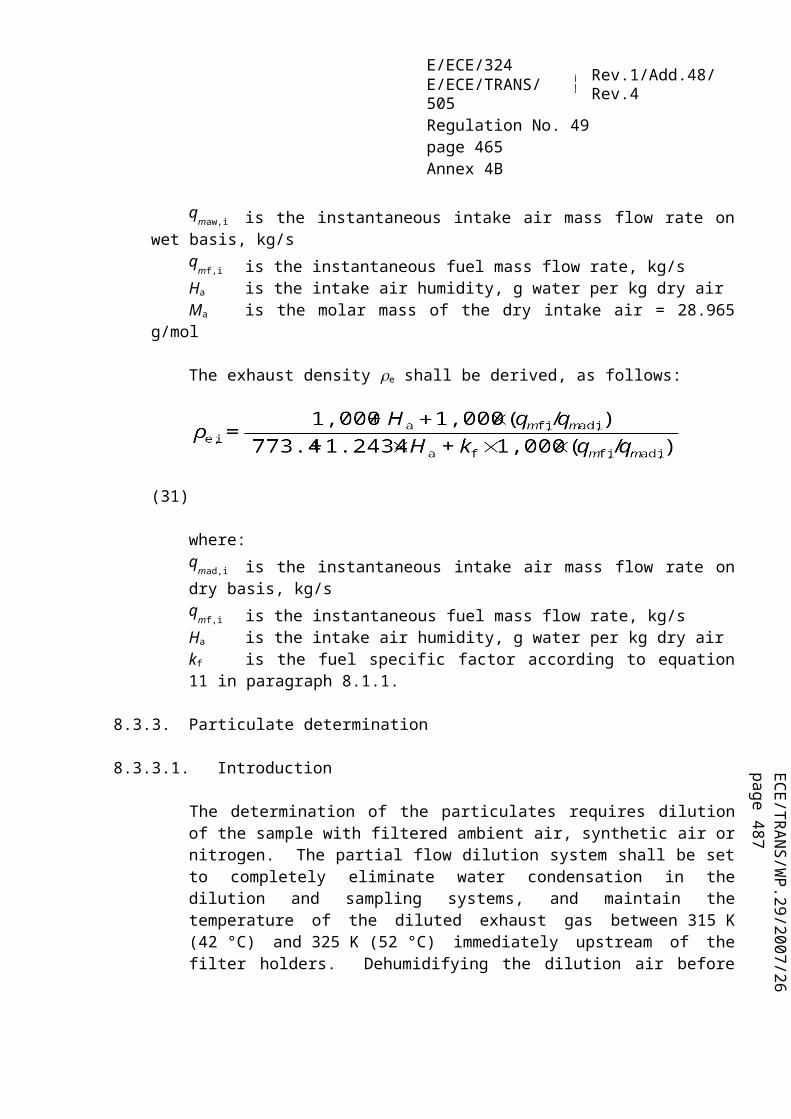
ECE/TR
AN
S/WP.29/2007/26
page 487
E/ECE/324E/ECE/TRANS/505 Rev.1/Add.48/Rev.4
Regulation No. 49page 465Annex 9B
------------------------
-----------------
- Figure B2 :
ENGINE ON ENGINE OFF
d) activation mode 4
e) activation mode 3
f) activation mode 2
g) activation mode 4 with "not ready" status.
h) activation mode 3 with "not ready" status.
Figure B.2: Malfunction display strategy: only the discriminatory strategy is applicable

E/ECE/324E/ECE/TRANS/505 Rev.1/Add.48/Rev.4
Regulation No. 49page 466Annex 9B
4.6.3. MI activation at "engine on"
When the key is placed in the on position and the engine is started (engine on), the MI shall be commanded off unless the provisions of paragraph 4.6.3.1. and/or paragraph 4.6.3.2. have been met.
4.6.3.1. MI display strategy
For the purpose of activating the MI, continuous-MI shall take precedence to short-MI and on-demand-MI. For the purpose of activating the MI, short-MI shall take precedence to on-demand-MI.
4.6.3.1.1. Class A malfunctions
The OBD system shall command a continuous-MI upon storage of a confirmed DTC associated with a Class A malfunction.
4.6.3.1.2. Class B malfunctions
The OBD system shall command a "short-MI" at the next key-on event following storage of a confirmed and active DTC associated with a Class B malfunction.
Whenever a B1 counter reaches 200 hours, the OBD system shall command a continuous-MI.
4.6.3.1.3. Class C malfunctions
The manufacturer may make available information on Class C malfunctions through the use of an on-demand-MI that shall be available until the engine is started.
4.6.3.1.4. MI de-activation scheme
The "continuous-MI" shall switch to a "short-MI" if a single monitoring event occurs and the malfunction that originally activated the continuous-MI is not detected during the current operating sequence and a continuous-MI is not activated due to another malfunction.
The "short-MI" shall be deactivated if the malfunction is not detected during 3 subsequent sequential operating sequences and the MI is not activated due to another Class A or B malfunction.

ECE/TR
AN
S/WP.29/2007/26
page 487
E/ECE/324E/ECE/TRANS/505 Rev.1/Add.48/Rev.4
Regulation No. 49page 467Annex 9B
4.6.4. MI activation at key-on/engine-off
The MI activation at key-on/engine-off shall consist of two sequences separated by a 5 seconds MI off:(a) the first sequence is designed to provide an indication of the MI functionality
and the readiness of the monitored components;(b) the second sequence is designed to provide an indication of the presence of a
malfunction.
The second sequence is repeated until engine is started (engine-on) or the key set on key-off position.
4.6.4.1. MI functionality/readiness
The MI shall show a steady indication for 5 seconds to indicate that the MI is functional.
The MI shall remain at the off position for 10 seconds.
The MI shall then remain at the on position for 5 seconds to indicate that the readiness for all monitored components is complete.
The MI shall blink once per second for 5 seconds to indicate that the readiness for one or more of the monitored components is not complete.
The MI shall then remain off for 5 seconds.
4.6.4.2. Presence / absence of a malfunction
Following the sequence described in paragraph 4.6.4.1, the MI shall indicate the presence of a malfunction by a series of flashes or a continuous illumination, depending on the applicable activation mode, as described in the following paragraphs, or absence of a malfunction by a series of single flashes. When applicable, each flash consists of a 1s MI-on followed by a 1s MI-off, and the series of flashes will be followed by a period of 5 seconds with the MI off.
Four activation modes are considered, where activation mode 4 shall take precedence over activation modes 1, 2 and 3, activation mode 3 shall take precedence over activation modes 1 and 2, and activation mode 2 shall take precedence over activation mode 1.

E/ECE/324E/ECE/TRANS/505 Rev.1/Add.48/Rev.4
Regulation No. 49page 468Annex 9B
4.6.4.2.1. Activation mode 1 - absence of malfunction
The MI shall blink for one flash.
4.6.4.2.2. Activation mode 2 - "On-demand-MI"
The MI shall show blink for two flashes if the OBD system would command an on-demand-MI according to the discriminatory display strategy described in paragraph 4.6.3.1.
4.6.4.2.3. Activation mode 3 - "short-MI"
The MI shall blink for three flashes if the OBD system would command a short-MI according to the discriminatory display strategy described in paragraph 4.6.3.1.
4.6.4.2.4. Activation mode 4 - "continuous-MI"
The MI shall remain continuously ON ("continuous-MI") if the OBD system would command a continuous-MI according to the discriminatory display strategy described in paragraph 4.6.3.1.
4.6.5. Counters associated with malfunctions
4.6.5.1. MI counters
4.6.5.1.1. Continuous-MI Counter
The OBD system shall contain a continuous-MI counter to record the number of hours during which the engine has been operated while a continuous-MI is activated.
The continuous-MI counter shall count up to the maximum value provided in a 2 byte counter with 1 hour resolution and hold that value unless the conditions allowing the counter to be reset to zero are met.
The continuous-MI counter shall operate as follows:(a) if starting from zero, the continuous-MI counter shall begin counting as soon as
a continuous-MI is activated;(b) the continuous-MI counter shall halt and hold its present value when the
continuous-MI is no longer activated;(c) the continuous-MI counter shall continue counting from the point at which it
had been held if a malfunction that results in a continuous-MI is detected within 3 operating sequences;

ECE/TR
AN
S/WP.29/2007/26
page 487
E/ECE/324E/ECE/TRANS/505 Rev.1/Add.48/Rev.4
Regulation No. 49page 469Annex 9B
(d) the continuous-MI counter shall start again counting from zero when a malfunction that results in a continuous-MI is detected after 3 operating sequences since the counter was last held;
(e) the continuous-MI counter shall be reset to zero when:(i) no malfunction that results in a continuous-MI is detected during 40
warm-up cycles or 200 engine operating hours since the counter was last held whichever occurs first; or
- (ii) the OBD scan tool commands the OBD System to clear OBD information.
Figure C1:Illustration of the MI counters activation principles
< 3 op. sequences
> 3 op. sequences
> 40 op. sequences
3 op. sequences 40 op. sequencesor 200 op. hours
Con
tinuo
us-M
I co
unte
rcu
mul
ativ
e M
I co
unte
rC
ontin
uous
-MI

E/ECE/324E/ECE/TRANS/505 Rev.1/Add.48/Rev.4
Regulation No. 49page 470Annex 9B
Figure C2:
Illustration of the B1 counter activation principles
4.6.5.1.2. Cumulative continuous-MI counter
The OBD system shall contain a cumulative continuous-MI counter to record the cumulative number of hours during which the engine has been operated over its life while a continuous-MI is activated.
The cumulative continuous-MI counter shall count up to the maximum value provided in a 2-byte counter with 1 hour resolution and hold that value.
The cumulative continuous-MI counter shall not be reset to zero by the engine system, a scan tool or a disconnection of a battery.
The cumulative continuous-MI counter shall operate as follows:(a) the cumulative continuous-MI counter shall begin counting when the
continuous-MI is activated.(b) the cumulative continuous-MI counter shall halt and hold its present value when
the continuous-MI is no longer activated.(c) the cumulative continuous-MI counter shall continue counting from the point
< 3 op. sequences
> 3 op. sequences
200 op. hours3 op. sequences
B1
coun
ter
B1
mal
func
tion
< 3 op. sequences
MI set continuously ON
YES
NO
190 hrs
200 hrs

ECE/TR
AN
S/WP.29/2007/26
page 487
E/ECE/324E/ECE/TRANS/505 Rev.1/Add.48/Rev.4
Regulation No. 49page 471Annex 9B
it had been held when a continuous-MI is activated.
Figure C1 illustrates the principle of the cumulative continuous-MI counter and Appendix 2 contains examples that illustrate the logic.
4.6.5.2. Counters associated with Class B1 malfunctions
4.6.5.2.1. Single B1-counter
The OBD system shall contain a B1 counter to record the number of hours during which the engine has operated while a Class B1 malfunction is present.
The B1 counter shall operate as follows:(a) the B1 counter shall begin counting as soon as a Class B1 malfunction is
detected and a confirmed and active DTC has been stored.(b) the B1 counter shall halt and hold its present value if no Class B1 malfunction
is confirmed and active, or when all Class B1 malfunction have been erased by a scan tool.
(c) the B1 counter shall continue counting from the point it had been held if a subsequent Class B1 malfunction is detected within 3 operating sequences.
In the case where the B1 counter has exceeded 200 engine running hours, the OBD system shall set the counter to 190 engine running hours when the OBD system has determined that a Class B1 malfunction is no longer confirmed and active, or when all Class B1 malfunctions have been erased by a scan tool. The B1 counter shall begin counting from 190 engine running hours if a subsequent Class B1 malfunction is present within 3 operating sequences.
The B1 counter shall be reset to zero when three consecutive operating sequences have occurred during which no Class B1 malfunctions have been detected.
Note: The B1 counter does not indicate the number of engine running hours with a single Class B1 malfunction present.
The B1 counter may accumulate the number of hours of 2 or more different Class B1 malfunctions, none of them having reached the time the counter indicates.
The B1 counter is only intended to determine when the continuous-MI shall be activated.
Figure C2 illustrates the principle of the B1 counter and Appendix 2 contains examples that illustrate the logic.
4.6.5.2.2. Multiple B1-counters

E/ECE/324E/ECE/TRANS/505 Rev.1/Add.48/Rev.4
Regulation No. 49page 472Annex 9B
A manufacturer may use multiple B1 counters. In that case the system shall be capable of assigning a specific B1 counter to each class B1 malfunction.
The control of the specific B1 counter shall follow the same rules as the single B1 counter, where each specific B1 counter shall begin counting when the assigned Class B1 malfunction is detected.
4.7. OBD information
4.7.1. Recorded information
The information recorded by the OBD system shall be available upon off-board request in the following packages manner:(a) information about the engine state;(b) information about active emission-related malfunctions;(c) information for repair.
4.7.1.1. Information about the engine state
This information will provide an enforcement agency 29/ with the malfunction indicator status and associated data (e.g. continuous-MI counter, readiness).
The OBD system shall provide all information (according to the applicable standard set in Appendix 6) for the external roadside check test equipment to assimilate the data and provide an enforcement agent with the following information:(a) discriminatory/non-discriminatory display strategy;(b) the VIN (vehicle identification number);(c) presence of a continuous-MI;(d) the readiness of the OBD system;(e) the number of engine operating hours during which a continuous-MI was last
activated (continuous-MI counter).
This information shall be read only access (i.e. no clearing).
29/ A typical use of this information package may be to establish basic emission road-worthiness of the engine system.

ECE/TR
AN
S/WP.29/2007/26
page 487
E/ECE/324E/ECE/TRANS/505 Rev.1/Add.48/Rev.4
Regulation No. 49page 473Annex 9B
4.7.1.2. Information about active emission-related malfunctions
This information will provide any inspection station 30/ with a subset of engine related OBD data including the malfunction indicator status and associated data (MI counters), a list of active/confirmed malfunctions of classes A and B and associated data (e.g. B1-counter).
The OBD system shall provide all information (according to the applicable standard set in Appendix 6) for the external inspection test equipment to assimilate the data and provide an inspector with the following information:(a) the gtr (and revision) number, to be integrated into Regulation No. 49 type
approval marking;(b) discriminatory/ non-discriminatory display strategy;(c) the VIN (vehicle identification number);(d) the Malfunction Indicator status;(e) the Readiness of the OBD system;(f) number of warm-up cycles and number of engine operating hours since
recorded OBD information was last cleared;(g) the number of engine operating hours during which a continuous-MI was last
activated (continuous-MI counter);(h) the cumulated operating hours with a continuous-MI (cumulative continuous-
MI counter);(i) the value of the B1 counter with the highest number of engine operating hours;(j) the confirmed and active DTCs for Class A malfunctions;(k) the confirmed and active DTCs for Classes B (B1 and B2) malfunctions;(l) the confirmed and active DTCs Class B1 malfunctions;(m) the software calibration identification(s);(n) the calibration verification number(s).
This information shall be read only access (i.e. no clearing).
4.7.1.3. Information for repair
This information will provide repair technicians with all OBD data specified in this annex (e.g. freeze frame information).
The OBD system shall provide all information (according to the applicable standard set in Appendix 6) for the external repair test equipment to assimilate the data and provide a repair technician with the following information:(a) gtr (and revision) number, to be integrated into Regulation No. 49 type
approval marking;(b) VIN (vehicle identification number);
30/ A typical use of this information package may be to establish detailed understanding of the emission road-worthiness of the engine system.

E/ECE/324E/ECE/TRANS/505 Rev.1/Add.48/Rev.4
Regulation No. 49page 474Annex 9B
(c) malfunction indicator status;(d) readiness of the OBD system;(e) number of warm-up cycles and number of engine operating hours since
recorded OBD information was last cleared;(f) monitor status (i.e. disabled for the rest of this drive cycle complete this drive
cycle, or not complete this drive cycle) since last engine shut-off for each monitor used for readiness status;
(g) number of engine operating hours since the malfunction indicator has been activated (continuous MI counter);
(h) confirmed and active DTCs for Class A malfunctions;(i) confirmed and active DTCs for Classes B (B1 and B2) malfunctions;(j) cumulated operating hours with a continuous-MI (cumulative continuous-MI
counter);(k) value of the B1 counter with the highest number of engine operating hours;(l) confirmed and active DTCs for Class B1 malfunctions and the number of
engine operating hours from the B1-counter(s);(m) confirmed and active DTCs for Class C malfunctions;(n) pending DTCs and their associated class;(o) previously active DTCs and their associated class;(p) real-time information on OEM selected and supported sensor signals, internal
and output signals (see paragraph 4.7.2 and Appendix 5);(q) freeze frame data requested by this annex (see paragraph 4.7.1.4. and
Appendix 5);(r) software calibration identification(s); (s) calibration verification number(s).
The OBD system shall clear all the recorded malfunctions of the engine system and related data (operating time information, freeze frame, etc.) in accordance with the provisions of this annex, when this request is provided via the external repair test equipment according to the applicable standard set in Appendix 6.
4.7.1.4. Freeze frame information
At least one "freeze frame" of information shall be stored at the time that either a potential DTC or a confirmed and active DTC is stored at the decision of the manufacturer. The manufacturer is allowed to update the freeze frame information whenever the pending DTC is detected again.
The freeze frame shall provide the operating conditions of the vehicle at the time of malfunction detection and the DTC associated with the stored data. The freeze frame shall include the information as shown in table 1 in Appendix 5 of this annex. The freeze frame shall also include all of the information in tables 2 and 3 of Appendix 5 of this annex that are used for monitoring or control purposes in the specific control unit that stored the DTC.

ECE/TR
AN
S/WP.29/2007/26
page 487
E/ECE/324E/ECE/TRANS/505 Rev.1/Add.48/Rev.4
Regulation No. 49page 475Annex 9B
Storage of freeze frame information associated with a Class A malfunction shall take precedence over information associated with a Class B1 malfunction which shall take precedence over information associated with a Class B2 malfunction and likewise for information associated with a Class C malfunction. The first malfunction detected shall take precedence over the most recent malfunction unless the most recent malfunction is of a higher class.
In case a device is monitored by the OBD system and is not be covered by Appendix 5 the freeze frame information shall include elements of information for the sensors and actuators of this device in a way similar to those described in Appendix 5. This shall be submitted for approval by the Approval Authority at the time of approval.
4.7.1.5. Readiness
A readiness shall be set to "complete" when a monitor or a group of monitors addressed by this status have run since the last erasing by request of an external OBD scan-tool. Readiness shall be set to "not complete" by erasing the fault code memory of a monitor or group of monitors by request of an external scan-tool.
Normal engine shutdown shall not cause the readiness to change.
The manufacturer may request, subject to approval by the Approval Authority, that the ready status for a monitor be set to indicate “complete” without the monitor having completed if monitoring is disabled for a multiple number of operating sequences due to the continued presence of extreme operating conditions (e.g. cold ambient temperatures, high altitudes). Any such request must specify the conditions for monitoring system disablement and the number of operating sequences that would pass without monitor completion before ready status would be indicated as "complete".
4.7.2 Data stream information
The OBD system shall make available to a scan tool in real time the information shown in tables 1 to 4 in Appendix 5 of this annex, upon request (actual signal values should be used in favour of surrogate values).
For the purpose of the calculated load and torque parameters, the OBD system shall report the most accurate values that are calculated within the applicable electronic control unit (e.g. the engine control computer).
E/ECE/324E/ECE/TRANS/505 Rev.1/Add.48/Rev.4
Regulation No. 49page 476Annex 9B
Table 1 in Appendix 5 gives the list of mandatory OBD information relating to the engine load and speed.
Table 2 in Appendix 5 shows the other OBD information which must be included if used by the emission or OBD system to enable or disable any OBD monitors.
Table 3 in Appendix 5 shows the information which is required to be included if the engine is so equipped, senses or calculates the information 31/. At the decision of the manufacturer, other freeze frame or data stream information may be included.
In case a device is monitored by the OBD system and is not covered by Appendix 5 (e.g. SCR), the data-stream information shall include elements of information for the sensors and actuators of this device in a way similar to those described in Appendix 5. This shall be submitted for approval by the Approval Authority at the time of approval.
4.7.3. Access to OBD information
Access to OBD information shall be provided only in accordance with the standards mentioned in Appendix 6 of this annex and the following sub-paragraphs 32/.
Access to the OBD information shall not be dependent on any access code or other device or method obtainable only from the manufacturer or its suppliers. Interpretation of the OBD information shall not require any unique decoding information, unless that information is publicly available.
A single access method (e.g. a single access point/node) to OBD information shall be supported to retrieve all OBD information. This method shall permit access to the complete OBD information required by this annex. This method shall also permit access to specific smaller information packages as defined in this annex (e.g. road worthiness information packages in case of emission related OBD)
Access to OBD information shall be provided using, at least one of the following series of standards mentioned in Appendix 6:(a) ISO/PAS 27145 (CAN-based)(b) ISO 27145 (TCP/IP-based)(c) SAE J1939-71
Access to OBD information shall be possible by the means of a wired connection.31/ It is not required to equip the engine for the sole purpose of providing the information data mentioned in tables 2 and 3 of Annex 5.32/ The manufacturer is allowed to use an additional on-board diagnostic display, such as a dashboard mounted video display device, for providing access to OBD information. Such an additional device is not subject to the requirements of this annex.

ECE/TR
AN
S/WP.29/2007/26
page 487
E/ECE/324E/ECE/TRANS/505 Rev.1/Add.48/Rev.4
Regulation No. 49page 477Annex 9B
OBD data shall be provided by the OBD system upon request using scan tool that complies with the requirements of the applicable standards mentioned in Appendix 6 (communication with external tester).
4.7.3.1. CAN based wired communication
The communication speed on the wired data link of the OBD system shall be either 250 kbps or 500 kbps.
It is the manufacturer's responsibility to select the baud-rate and to design the OBD system according to the requirements specified in the standards mentioned in Appendix 6, and referred to in this annex. The OBD system shall be tolerant against the automatic detection between these two baud-rates exercised by the external test equipment.
The connection interface between the vehicle and the external diagnostic test equipment (e.g. scan-tool) shall be standardised and shall meet all of the requirements of ISO 15031-3 Type A (12 VDC power supply), Type B (24 VDC power supply) or SAE J1939-13 (12 or 24 VDC power supply).
4.7.3.2. (reserved for TCP/IP (Ethernet) based wired communication.)
4.7.3.3. Connector location
The connector shall be located in the driver's side foot-well region of the vehicle interior in the area bound by the driver's side of the vehicle and the driver's side edge of the centre console (or the vehicle centreline if the vehicle does not have a centre console) and at a location no higher than the bottom of the steering wheel when in the lowest adjustable position. The connector may not be located on or in the centre console (i.e. neither on the horizontal faces near the floor-mounted gear selector, parking brake lever, or cup holders nor on the vertical faces near the stereo/radio, climate system, or navigation system controls). The location of the connector shall be capable of being easily identified and accessed (e.g. to connect an off-board tool). For vehicles equipped with a driver's side door, the connector shall be capable of being easily identified and accessed by someone standing (or "crouched") outside the driver's side of the vehicle with the driver's side door open.
The Approval Authority may approve upon request of the manufacturer an alternative location provided the installation position shall be easily accessible and protected from accidental damage during normal conditions of use, e.g. the location as described in ISO 15031 series of standards.

E/ECE/324E/ECE/TRANS/505 Rev.1/Add.48/Rev.4
Regulation No. 49page 478Annex 9B
If the connector is covered or located in a specific equipment box, the cover or the compartment door must be removable by hand without the use of any tools and be clearly labelled "OBD" to identify the location of the connector.
The manufacturer may equip vehicles with additional diagnostic connectors and data-links for manufacturer-specific purposes other than the required OBD functions. If the additional connector conforms to one of the standard diagnostic connectors allowed in Appendix 6, only the connector required by this annex shall be clearly labelled "OBD" to distinguish it from other similar connectors.
4.7.4. Erasing / resetting OBD information by a scan-tool
On request of the scan tool, the following data shall be erased or reset to the value specified in this annex from the computer memory.
OBD information data Erasable Resetable 33/malfunction indicator status Xreadiness of the OBD system Xnumber of engine operating hours since the malfunction indicator has been activated (continuous MI counter) X
all DTCs Xthe value of the B1 counter with the highest number of engine operating hours X
the number of engine operating hours from the B1-counter(s) Xthe freeze frame data requested by this annex X
OBD information shall not be erased by disconnection of the vehicle's battery(s).
4.8. Electronic security
Any vehicle with an emission control unit must include features to deter modification, except as authorized by the manufacturer. The manufacturer shall authorize modifications if these modifications are necessary for the diagnosis, servicing, inspection, retrofitting or repair of the vehicle.
Any reprogramable computer codes or operating parameters shall be resistant to tampering and afford a level of protection at least as good as the provisions in ISO 15031-7 (SAE J2186) or J1939-73 provided that the security exchange is conducted using the protocols and diagnostic connector as prescribed in this annex. Any removable calibration memory chips shall be potted, encased in a sealed container or protected by electronic algorithms and shall not be changeable without the use of specialised tools and procedures.
33/ to the value specified in the appropriate section of this annex

ECE/TR
AN
S/WP.29/2007/26
page 487
E/ECE/324E/ECE/TRANS/505 Rev.1/Add.48/Rev.4
Regulation No. 49page 479Annex 9B
Computer-coded engine operating parameters shall not be changeable without the use of specialised tools and procedures (e.g. soldered or potted computer components or sealed (or soldered) computer enclosures).
Manufacturers shall take adequate steps to protect the maximum fuel delivery setting from tampering while a vehicle is in-service.
Manufacturers may apply to the Approval Authority for an exemption from one of these requirements for those vehicles that are unlikely to require protection. The criteria that the Approval Authority will evaluate in considering an exemption will include, but are not limited to, the current availability of performance chips, the high-performance capability of the vehicle and the projected sales volume of the vehicle.
Manufacturers using programmable computer code systems (e.g. electrical erasable programmable read-only memory, EEPROM) shall deter unauthorized reprogramming. Manufacturers shall include enhanced tamper-protection strategies and write protect features requiring electronic access to an off-site computer maintained by the manufacturer. Alternative methods giving an equivalent level of tamper protection may be approved by the Approval Authority
4.9. Durability of the OBD system
The OBD system shall be designed and constructed so as to enable it to identify types of malfunctions over the complete life of the vehicle or engine system.
Any additional provisions addressing the durability of OBD systems are contained in this annex.
An OBD system shall not be programmed or otherwise designed to partially or totally deactivate based on age and/or mileage of the vehicle during the actual life of the vehicle, nor shall the system contain any algorithm or strategy designed to reduce the effectiveness of the OBD system over time.
5. PERFORMANCE REQUIREMENTS
5.1. Thresholds
The OTLs for the applicable monitoring criteria defined in Appendix 3 are defined in the main part of this Regulation

E/ECE/324E/ECE/TRANS/505 Rev.1/Add.48/Rev.4
Regulation No. 49page 480Annex 9B
5.2. Temporary disablement of the OBD system
Approval authorities may approve that an OBD system be temporarily disabled under the conditions specified in the following sub-paragraphs.
At the time of approval or type-approval, the manufacturer shall provide the Approval Authority with the detailed description of each of the OBD system's temporary disablement strategies and the data and/or engineering evaluation demonstrating that monitoring during the applicable conditions would be unreliable or impractical.
In all cases, monitoring shall resume once the conditions justifying temporary disablement are no longer present.
5.2.1. Engine/vehicle operational safety
Manufacturers may request approval to disable the affected OBD monitoring systems when operational safety strategies are activated.
The OBD monitoring system is not required to evaluate components during malfunction if such evaluation would result in a risk to the safe use of the vehicle.
5.2.2. Ambient temperature and altitude conditions
Manufacturers may request approval to disable OBD system monitors at ambient engine start temperatures below 266 K (-7 degrees Celsius or 20 degrees Fahrenheit) or above 308 K (35 degrees Celsius or 95 degrees Fahrenheit), or at elevations above 2,500 meters (8,202 feet) above sea level.
A manufacturer may further request approval that an OBD system monitor be disabled at other ambient engine start temperatures upon determining that the manufacturer has demonstrated with data and/or an engineering evaluation that misdiagnosis would occur at the ambient temperatures because of its effect on the component itself (e.g. component freezing).
Note: Ambient conditions may be estimated by indirect methods. For example ambient temperature conditions may be determined based on intake air temperature.
5.2.3. Low fuel level
Manufacturers may request approval to disable monitoring systems that are affected by low fuel level or running out of fuel (e.g. diagnosis of a malfunction of the fuelling system or misfiring). The low fuel level considered for such a disablement
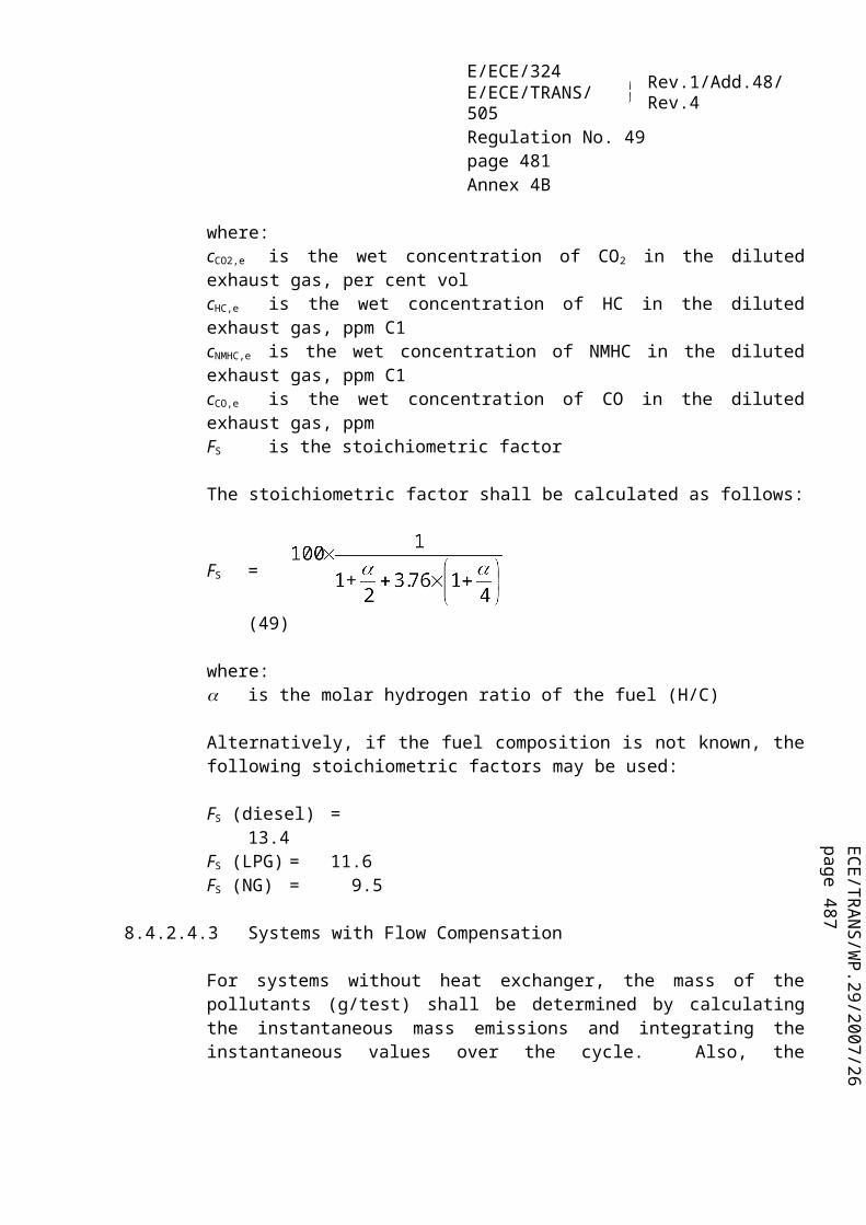
ECE/TR
AN
S/WP.29/2007/26
page 487
E/ECE/324E/ECE/TRANS/505 Rev.1/Add.48/Rev.4
Regulation No. 49page 481Annex 9B
shall not exceed 100 litres or 20 per cent of the nominal capacity of the fuel tank, whichever is lower.
5.2.4. Vehicle battery or system voltage levels
Manufacturers may request approval to disable monitoring systems that can be affected by vehicle battery or system voltage levels.
5.2.4.1. Low voltage
For monitoring systems affected by low vehicle battery or system voltages, manufacturers may request approval to disable monitoring systems when the battery or system voltage is below 90 per cent of the nominal voltage (or 11.0 Volts for a 12 Volt battery, 22.0 Volts for a 24 volt battery). Manufacturers may request approval to utilize a voltage threshold higher than this value to disable system monitoring.
The manufacturer shall demonstrate that monitoring at the voltages would be unreliable and that either operation of a vehicle below the disablement criteria for extended periods of time is unlikely or the OBD system monitors the battery or system voltage and will detect a malfunction at the voltage used to disable other monitors.
5.2.4.2. High voltage
For emission related monitoring systems affected by high vehicle battery or system voltages, manufacturers may request approval to disable monitoring systems when the battery or system voltage exceeds a manufacturer-defined voltage.
The manufacturer shall demonstrate that monitoring above the manufacturer-defined voltage would be unreliable and that either the electrical charging system/alternator warning light is illuminated (or voltage gauge is in the "red zone") or the OBD system monitors the battery or system voltage and will detect a malfunction at the voltage used to disable other monitors.
5.2.5. Active PTO (power take-off units)
The manufacturer may request approval to temporarily disable affected monitoring systems in vehicles equipped with a PTO unit, under the condition where that PTO unit is temporarily active.

E/ECE/324E/ECE/TRANS/505 Rev.1/Add.48/Rev.4
Regulation No. 49page 482Annex 9B
5.2.6. Forced regeneration
The manufacturer may request approval to disable the affected OBD monitoring systems during the forced regeneration of an emission control system downstream of the engine (e.g. a particulate filter).
5.2.7. AECS
The manufacturer may request approval to disable OBD system monitors during the operation of an AECS, including MECS, under conditions not already covered in paragraph 5.2. if the monitoring capability of a monitor is affected by the operation of an AECS.
6. DEMONSTRATION REQUIREMENTS
The basic elements for demonstrating the compliance of an OBD system with the requirements of this annex are as follows:(a) procedure for selecting the OBD-parent engine system. The OBD-parent
engine system is selected by the manufacturer in agreement with the Approval Authority.
(b) procedure for demonstrating the classification of a malfunction. The manufacturer submits to the Approval Authority the classification of each malfunction for that OBD-parent engine system and the necessary supporting data in order to justify each classification.
(c) procedure for qualifying a deteriorated component. The manufacturer shall provide, on request of the Approval Authority, deteriorated components for OBD testing purposes. These components are qualified on the basis of supporting data provided by the manufacturer.
6.1. Emission-OBD family
The manufacturer is responsible for determining the composition of an emission-OBD family. Grouping engine systems within an emission-OBD family shall be based on good engineering judgement and be subject to approval by the Approval Authority.
Engines that do not belong to the same engine family may still belong to the same emission-OBD family.
6.1.1. Parameters defining an emission-OBD family
An emission-OBD family is characterised by basic design parameters that shall be common to engine systems within the family.
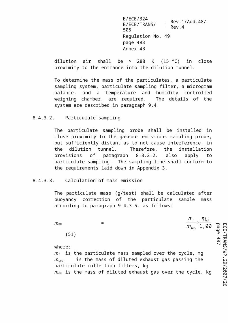
ECE/TR
AN
S/WP.29/2007/26
page 487
E/ECE/324E/ECE/TRANS/505 Rev.1/Add.48/Rev.4
Regulation No. 49page 483Annex 9B
In order that engine systems are considered to belong to the same OBD-engine family, the following list of basic parameters shall be similar:(a) mission control systems(b) methods of OBD monitoring(c) criteria for performance and component monitoring(d) monitoring parameters (e.g. frequency)
These similarities shall be demonstrated by the manufacturer by means of relevant engineering demonstration or other appropriate procedures and subject to the approval of the Approval Authority.
The manufacturer may request approval by the Approval Authority of minor differences in the methods of monitoring/diagnosing the engine emission control system due to engine system configuration variation, when these methods are considered similar by the manufacturer and:(a) they differ only to match specificities of the considered components (e.g. size,
exhaust flow, etc.); or(b) their similarities are based on good engineering judgement.
6.1.2. OBD-parent engine system
Compliance of an emission-OBD family with the requirements of this annex is achieved by demonstrating the compliance of the OBD-parent engine system of this family.
The selection of the OBD-parent engine system is made by the manufacturer and subject to the approval of the Approval Authority.
Prior to testing the Approval Authority may decide to request the manufacturer to select an additional engine for demonstration.
The manufacturer may also propose to the Approval Authority to test additional engines to cover the complete emission-OBD family.
6.2. Procedures for demonstrating the malfunction classification
The manufacturer shall provide the documentation justifying the proper classification of each malfunction to the Approval Authority. This documentation shall include a failure analysis (for example elements of a "failure mode and effect analysis") and may also include:(a) simulation results(b) test results(c) reference to previously approved classification

E/ECE/324E/ECE/TRANS/505 Rev.1/Add.48/Rev.4
Regulation No. 49page 484Annex 9B
In the following paragraphs the requirements for demonstrating the correct classification are listed, including requirements for testing. The minimum number of tests is four and the maximum number of tests is four times the number of engine families considered within the emission OBD family. The Approval Authority may decide to curtail the test at any time before this maximum number of failure tests has been reached.
In specific cases where the classification testing is not possible (for example, if an MECS is activated and the engine cannot run the applicable test, etc.), the malfunction may be classified based on technical justification. This exception shall be documented by the manufacturer and is subject to the agreement of the Approval Authority.
6.2.1. Demonstration of classification into A
The classification by the manufacturer of a malfunction into Class A shall not be subject to a demonstration test.
If the Approval Authority disagrees with a manufacturer's classification of a malfunction as Class A, the Approval Authority requires the classification of the malfunction into Class B1, B2 or C, as appropriate.
In that case the approval document shall record that the malfunction classification has been assigned according to the request of the Approval Authority.
6.2.2. Demonstration of classification into B1 (distinguishing between A and B1)
In order to justify the classification of a malfunction into Class B1 the documentation shall clearly demonstrate that, in some circumstances 34/, the malfunction results in emissions that are lower than the OTLs.
In the case that the Approval Authority requires an emission test for demonstrating the classification of a malfunction into Class B1 the manufacturer shall demonstrate that the emissions due to that particular malfunction are, in selected circumstances, below the OTLs:(a) the manufacturer selects the circumstances of the test in agreement with the
Approval Authority;(b) the manufacturer shall not be required to demonstrate that in other
circumstances the emissions due to the malfunction are actually above the OTLs.
If the manufacturer fails to demonstrate the classification as Class B1, the 34/ Examples of circumstances that may influence if and when OTLs are exceeded are the age of the engine system or whether the test is conducted with a new or aged component.

ECE/TR
AN
S/WP.29/2007/26
page 487
E/ECE/324E/ECE/TRANS/505 Rev.1/Add.48/Rev.4
Regulation No. 49page 485Annex 9B
malfunction is classified as Class A.
6.2.3. Demonstration of classification into B1 (distinguishing between B2 and B1)
If the Approval Authority disagrees with a manufacturer's classification of a malfunction as Class B1 because it considers that the OTLs are not exceeded, the Approval Authority requires the reclassification of that malfunction into Class B2 or C. In that case the approval documents shall record that the malfunction classification has been assigned according to the request of the Approval Authority.
6.2.4. Demonstration of classification into B2 (distinguishing between B2 and B1)
In order to justify the classification of a malfunction into Class B2 the manufacturer shall demonstrate that emissions are lower than the OTLs.
In case the Approval Authority disagrees with the classification of a malfunction as Class B2 because it considers that the OTLs are exceeded, the manufacturer may be required to demonstrate by testing that the emissions due to the malfunction are below the OTLs. If the test fails, then the Approval Authority shall require the reclassification of that malfunction into A or B1 and the manufacturer shall subsequently demonstrate the appropriate classification and the documentation shall be updated.
6.2.5. Demonstration of classification into B2 (distinguishing between B2 and C)
If the Approval Authority disagrees with a manufacturer's classification of a malfunction as Class B2 because it considers the regulated emission limits are not exceeded, the Approval Authority requires the reclassification of that malfunction into Class C. In that case the approval documents shall record that the malfunction classification has been assigned according to the request of the Approval Authority.
6.2.6. Demonstration of classification into C
In order to justify the classification of a malfunction into Class C the manufacturer shall demonstrate that emissions are lower than the regulated emission limits.
In case the Approval Authority disagrees with the classification of a malfunction as Class C the manufacturer may be required to demonstrate by testing that the emissions due to the malfunction are below the regulated emission limits.
If the test fails, then the Approval Authority shall request the reclassification of that malfunction and the manufacturer shall subsequently demonstrate the appropriate reclassification and the documentation shall be updated.

E/ECE/324E/ECE/TRANS/505 Rev.1/Add.48/Rev.4
Regulation No. 49page 486Annex 9B
6.3. Procedures for demonstrating the OBD performance
The manufacturer shall submit to the Approval Authority a complete documentation package justifying the compliance of the OBD system as regards its monitoring capability, which may include:(a) algorithms and decision charts(b) tests and/or simulation results(c) reference to previously approved monitoring systems, etc.
In the following paragraphs the requirements for demonstrating the OBD performance are listed, including requirements for testing. The minimum number of tests is four and the maximum number of tests is four times the number of engine families considered within the emission OBD family. The Approval Authority may decide to curtail the test at any time before this maximum number of failure tests has been reached.
6.3.1. Procedures for demonstrating the OBD performance by testing
In addition to the supporting data referred to in paragraph 6.3., the manufacturer shall demonstrate the proper monitoring of specific emission control systems or components by testing them on an engine test-bed according to the test procedures specified in paragraph 7.2. of this annex.
In that case, the manufacturer shall make available the qualified deteriorated components or the electrical device which would be used to simulate a malfunction.
The proper detection of the malfunction by the OBD system and its proper response to that detection (cf. MI indication, DTC storage, etc.) shall be demonstrated according to paragraph 7.2.
6.3.2. Procedures for qualifying a deteriorated component (or system)
This paragraph applies to the cases where the malfunction selected for an OBD demonstration test is monitored against tailpipe emissions 35/ (emission threshold monitoring - see paragraph 4.2.), by an emission test, the qualification of that deteriorated component.
In very specific cases the qualification of deteriorated components or systems by testing may not be possible (for example, if an MECS is activated and the engine cannot run the applicable test, etc.). In such cases, the deteriorated component shall be qualified without testing. This exception shall be documented by the manufacturer and is subject to the agreement of the Approval Authority.
35/ This paragraph will be extended to other monitors than mission threshold monitors at a later stage.

ECE/TR
AN
S/WP.29/2007/26
page 487
E/ECE/324E/ECE/TRANS/505 Rev.1/Add.48/Rev.4
Regulation No. 49page 487Annex 9B
6.3.2.1. Procedure for qualifying a deteriorated component used to demonstrate the detection of classes A and B1 malfunctions
In the case the malfunction selected by the Approval Authority results in tailpipe emissions that may exceed an OBD threshold limit, the manufacturer shall demonstrate by an emission test according to paragraph 7. that the deteriorated component or device does not result in the relevant emission exceeding its OTL by more than 20 per cent.
6.3.2.2. Qualification of deteriorated components used to demonstrate the detection of Class B2 malfunctions
In the case of Class B2 malfunctions, and upon request of the Approval Authority, the manufacturer shall demonstrate by an emission test according to paragraph 7. that the deteriorated component or device does not lead the relevant emission to exceed its applicable OTL.
6.3.2.3. Qualification of deteriorated components used to demonstrate the detection of Class C malfunctions
In the case of Class C malfunctions, and upon request of the Approval Authority, the manufacturer shall demonstrate by an emission test according to paragraph 7. that the deteriorated component or device does not lead the relevant emission to exceed its applicable regulated emission limit.
6.3.3. Test report
The test report shall contain, at a minimum, the information set out in Appendix 4.
6.4. Approval of an OBD system containing deficiencies
6.4.1. Approval authorities may approve upon request of a manufacturer an OBD system even though the system contains one or more deficiencies.
In considering the request, the Approval Authority shall determine whether compliance with the requirements of this annex is feasible or unreasonable.

E/ECE/324E/ECE/TRANS/505 Rev.1/Add.48/Rev.4
Regulation No. 49page 488Annex 9B
The Approval Authority shall take into consideration data from the manufacturer that details such factors as, but not limited to, technical feasibility, lead time and production cycles including phase-in or phase-out of engines designs and programmed upgrades of computers, the extend to which the resultant OBD system will be effective in complying with the requirements of this annex and that the manufacturer has demonstrated an acceptable level of effort toward meeting the requirements of the annex.
The Approval Authority will not accept any deficiency request that includes the complete lack of a required diagnostic monitor (i.e. a complete lack of the monitors required in Appendix 3).
6.4.2. Deficiency period
A deficiency is granted for a period of one year after the date of approval of the engine system.
If the manufacturer can adequately demonstrate to the Approval Authority that substantial engine modifications and additional lead time would be necessary to correct the deficiency, then this deficiency can be granted again for an additional one year, provided that the total deficiency period does not exceed 3 years (i.e. 3 times one year deficiency allowance is permitted).
The manufacturer cannot apply for a renewal of the deficiency period.
7. TEST PROCEDURES
7.1. Testing process
The demonstration by testing of the proper malfunction classification and the demonstration by testing of the proper monitoring performance of an OBD system are issues that shall be considered separately during the testing process. For example, a Class A malfunction will not require a classification test while it may be subject to an OBD performance test.
Where appropriate, the same test may be used to demonstrate the correct classification of a malfunction, the qualification of a deteriorated component provided by the manufacturer and the correct monitoring by the OBD system.
The engine system on which the OBD system is tested shall comply with the emission requirements of this Regulation.
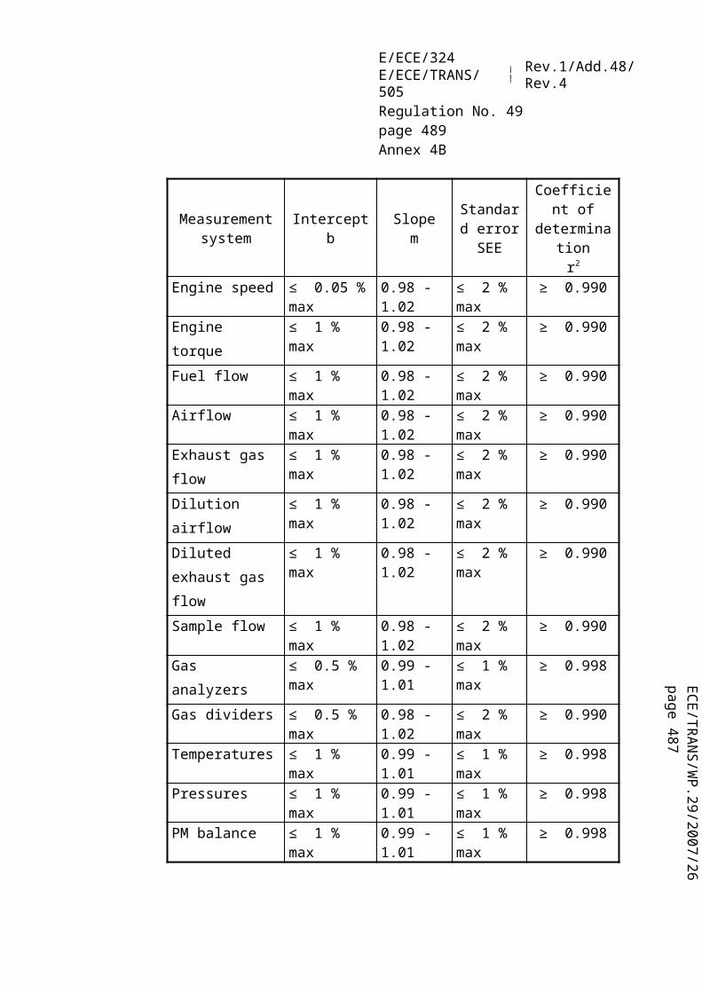
ECE/TR
AN
S/WP.29/2007/26
page 487
E/ECE/324E/ECE/TRANS/505 Rev.1/Add.48/Rev.4
Regulation No. 49page 489Annex 9B
7.1.1. Testing process for demonstrating the malfunction classification
When, according to paragraph 6.2., the Approval Authority requests the manufacturer to justify by testing the classification of a specific malfunction, the compliance demonstration will consist of a series of emission tests.
According to paragraph 6.2.2., when testing is required by the Approval Authority to justify the classification of a malfunction into Class B1 rather than in Class A, the manufacturer shall demonstrate that the emissions due to that particular malfunction are, in selected circumstances, below the OTLs:(a) the manufacturer selects these circumstances of test in agreement with the
Approval Authority(b) the manufacturer shall not be required to demonstrate that in other
circumstances the emissions due to the malfunction are actually above the OTLs.
The emission test may be repeated upon request of the manufacturer up to three times.
If any of these tests leads to emissions below the considered OTL, then the malfunction classification into Class B1 shall be approved.
When testing is required by the Approval Authority to justify the classification of a malfunction into Class B2 rather than in Class B1 or into Class C rather than in Class B2, the emission test shall not be repeated. If the emissions measured in the test are above the OTL or the emission limit, respectively, then the malfunction shall require a reclassification.
Note: According to paragraph 6.2.1., this paragraph does not apply to malfunctions classified into Class A.
7.1.2. Testing process for demonstrating the OBD performance
When the Approval Authority requests according to paragraph 6.3. to test the OBD system performance, the compliance demonstration shall consist of the following phases:(a) a malfunction is selected by the Approval Authority and a corresponding
deteriorated component or system shall be made available by the manufacturer;(b) when appropriate and if requested, the manufacturer shall demonstrate by an
emission test that the deteriorated component is qualified for a monitoring demonstration;
(c) the manufacturer shall demonstrate that the OBD system responds in a manner that complies with the provisions of this annex (i.e. MI indication, DTC storage, etc.) At the latest by the end of a series of OBD test-cycles.
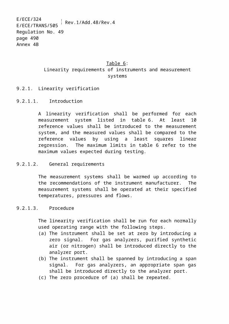
E/ECE/324E/ECE/TRANS/505 Rev.1/Add.48/Rev.4
Regulation No. 49page 490Annex 9B
7.1.2.1. Qualification of the deteriorated component
When the Approval Authority requests the manufacturer to qualify a deteriorated component by testing according to paragraph 6.3.2., this demonstration shall be made by performing an emissions test.
If it is determined that the installation of a deteriorated component or device on an engine system means that a comparison with the OBD threshold limits is not possible (e.g. because the statistical conditions for validating the applicable emission test cycle are not met), the malfunction of that component or device may be considered as qualified upon the agreement of the Approval Authority based on technical rationale provided by the manufacturer.
In the case that the installation of a deteriorated component or device on an engine means that the full load curve (as determined with a correctly operating engine) cannot be attained during the test, the deteriorated component or device may be considered as qualified upon the agreement of the Approval Authority based on technical rationale provided by the manufacturer.
7.1.2.2. Malfunction detection
Each monitor selected by the Approval Authority to be tested on an engine test-bed, shall respond to the introduction of a qualified deteriorated component in a manner that meets the requirements of this annex within two consecutive OBD test-cycles according to paragraph 7.2.2. of this annex.
When it has been specified in the monitoring description and agreed by the Approval Authority that a specific monitor needs more than two operating sequences to complete its monitoring, the number of OBD test-cycles may be increased according to the manufacturer's request.
Each individual OBD test-cycle in the demonstration test shall be separated by an engine shut-off. The time until the next start-up shall take into consideration any monitoring that may occur after engine shut-off and any necessary condition that must exist for monitoring to occur at the next start up.
The test is considered complete as soon as the OBD system has responded in a manner that meets the requirements of this annex.

ECE/TR
AN
S/WP.29/2007/26
page 487
E/ECE/324E/ECE/TRANS/505 Rev.1/Add.48/Rev.4
Regulation No. 49page 491Annex 9B
7.2. Applicable tests
The emission test is the test-cycle used for the measurement of the regulated emissions.
The OBD test-cycle is the test-cycle used when evaluating the performance of the OBD monitor. In many cases these test-cycles are the same.
7.2.1. Emission test cycle
The test-cycle considered in this annex for measuring emissions is the WHTC test-cycle as described in Annex 4B.
7.2.2. OBD test cycle
The World-wide harmonized OBD test-cycle considered in this annex is the hot part of the WHTC cycle as described in Annex 4B.
On request of the manufacturer and with approval of the Approval Authority, the cold part of the WHTC cycle can be used as an alternative OBD test-cycle. The request shall contain elements (technical considerations, simulation, test results, etc.) demonstrating:(a) the requested test-cycle results in a monitor that will run in real world driving,
and;(b) the applicable world-wide harmonized or regionally accepted OBD test-cycle
is shown to be less appropriate for the considered monitoring (e.g. fluid consumption monitoring).
7.2.3. Test operating conditions
The conditions (i.e. temperature, altitude, fuel quality etc.) for conducting the tests referred to in paragraphs 7.2.1. and 7.2.2. shall be those required for operating the WHTC test cycle as described in Annex 4B.
In the case of an emission test aimed at justifying the classification of a specific malfunction into Class B1, the test operating conditions may, per decision of the manufacturer, deviate from the ones in the paragraphs above according to paragraph 6.2.2.
7.3. Test reports
The test report shall contain, at a minimum, the information set out in Appendix 4.

E/ECE/324E/ECE/TRANS/505 Rev.1/Add.48/Rev.4
Regulation No. 49page 492Annex 9B
8. DOCUMENTATION REQUIREMENTS
8.1. Documentation for purpose of approval
The manufacturer shall provide a documentation package that includes a full description of the OBD system. The documentation package shall be made available in two parts:(a) a first part, which may be brief, provided that it exhibits evidence concerning
the relationships between monitors, sensors/actuators, and operating conditions (i.e. describes all enable conditions for monitors to run and disable conditions that cause monitors not to run). The documentation shall describe the functional operation of the OBD, including the malfunction ranking within the hierarchical classification. This material shall be retained by the Approval Authority. This information may be made available to interested parties upon request.
(b) a second part containing any data, including details of qualified deteriorated components or systems and associated test results, which are used as evidence to support the decision process referred to above, and a listing of all input and output signals that are available to the engine system and monitored by the OBD system. This second part shall also outline each monitoring strategy and the decision process.
This second part shall remain strictly confidential. It may be kept by the Approval Authority, or, at the discretion of the Approval Authority, may be retained by the manufacturer but shall be made open for inspection by the Approval Authority at the time of approval or at any time during the validity of the approval.
8.1.1. Documentation associated with each monitored component or system
The documentation package included in the second part shall contain but shall not be limited to the following information for each monitored component or system:(a) the malfunctions and associated DTC(s);(b) the monitoring method used for malfunction detection;(c) the parameters used and the conditions necessary for malfunction detection
and when applicable the fault criteria limits (performance and component monitoring);
(d) the criteria for storing a DTC;(e) the monitoring "time length" (i.e. the operation time/procedure necessary to
complete the monitoring) and the monitoring "frequency" (e.g. continuous, once per trip, etc.).

ECE/TR
AN
S/WP.29/2007/26
page 487
E/ECE/324E/ECE/TRANS/505 Rev.1/Add.48/Rev.4
Regulation No. 49page 493Annex 9B
8.1.2. Documentation associated with the malfunction classification
The documentation package included in the second part shall contain but shall not be limited to the following information for malfunction classification:
The malfunction classification of each DTC shall be documented. This classification may be different for different engine types (e.g. different engine ratings) within the same emission-OBD family.
This information shall include the technical justification required in paragraph 4.2. of this annex for classification into Class A, Class B1 or Class B2.
8.1.3. Documentation associated with the emission-OBD family
The documentation package included in the second part shall contain but shall not be limited to the following information for emission OBD-family:
A description of the emission-OBD family shall be provided. This description shall include a list and a description of the engine types within the family, the description of the OBD-parent engine system, and all elements that characterise the family according to paragraph 6.1.1. of this annex.
In the case where the emission-OBD family includes engines belonging to different engine families, a summary description of these engine families shall be provided.
In addition, the manufacturer shall provide a list of all electronic input and output an identification of the communication protocol utilized by each emission-OBD family.
8.2. Documentation for installing in a vehicle an OBD equipped engine system
The engine manufacturer shall include in the installation documents of its engine system the appropriate requirements that will ensure the vehicle, when used on the road or elsewhere as appropriate, will comply with the requirements of this annex. This documentation shall include but is not limited to:(a) the detailed technical requirements, including the provisions ensuring the
compatibility with the OBD system of the engine system;(b) the verification procedure to be completed.
The existence and the adequacy of such installation requirements may be checked during the approval process of the engine system.
Note: In the case a vehicle manufacturer applies for a direct approval of the installation of the OBD system on the vehicle, this documentation is not required.

E/ECE/324E/ECE/TRANS/505 Rev.1/Add.48/Rev.4
Regulation No. 49page 494Annex 9B
8.3. Documentation regarding OBD related information
Requirements of Appendix 7 have to be fulfilled.
9. APPENDICES
Appendix 1: Approval of installation of OBD systemsAppendix 2: Malfunctions - Illustration of the DTC status - illustration of the
MI and counters activation schemesAppendix 3: Monitoring RequirementsAppendix 4: Technical compliance REPORTAppendix 5: Freeze frame and data stream informationAppendix 6: Reference Standard DocumentsAppendix 7: Documentation regarding OBD related information

ECE/TR
AN
S/WP.29/2007/26
page 487
E/ECE/324E/ECE/TRANS/505 Rev.1/Add.48/Rev.4
Regulation No. 49page 495Annex 9B – Apendix 1
Annex 9B - Appendix 1
APPROVAL OF INSTALLATION OF OBD SYSTEMS
This appendix considers the case where the vehicle manufacturer requests approval of the installation on a vehicle of (an) OBD system(s) within an emission OBD family, that is (are) certified to the requirements of this annex.
In this case, and in addition to the general requirements of this annex, a demonstration of the correct installation is required. This demonstration shall be done on the basis of the appropriate element of design, results of verification tests, etc. and address the conformity of the following elements to the requirements of this annex:
(a) the installation on-board the vehicle as regards its compatibility with the OBD system of the engine-system;
(b) the MI (pictogram, activation schemes, etc.);(c) the wired communication interface.
Correct MI illumination, information storage and on-board off-board OBD communication will be checked. But any check shall not force dismounting the engine system (e.g. an electric disconnection may be selected).

E/ECE/324E/ECE/TRANS/505 Rev.1/Add.48/Rev.4
Regulation No. 49page 496Annex 9B – Appendix 2
Annex 9B - Appendix 2
MALFUNCTIONSILLUSTRATION OF THE DTC STATUS
ILLUSTRATION OF THE MI AND COUNTERS ACTIVATION SCHEMES
This appendix aims at illustrating the requirements set in paragraphs 4.3. and 4.6.6. of this annex.
It contains the following figures:
Figure 1: DTC status in case of a class B1 malfunctionFigure 2 DTC status in case of 2 consecutive different class B1 malfunctionsFigure 3: DTC status in case of the re-occurrence of a class B1 malfunctionFigure 4: Class A malfunction -activation of the MI and MI countersFigure 5: Class B1 malfunction - activation of the B1 counter in 5 use Cases.
Figure 1: DTC status in case of a class B1 malfunction
Notes: means the point a monitoring of the concerned malfunction occursN, M The annex requires the identification of "key" operating sequences during which some
events occurs, and the counting of the subsequent operating sequences. For the purpose of illustrating this requirement, the "key" operating sequences have been given the values N and M.E.g. M means the first operating sequence following the detection of a potential malfunction, and N means the operating sequence during which the MI is switched OFF.

ECE/TR
AN
S/WP.29/2007/26
page 487
E/ECE/324E/ECE/TRANS/505 Rev.1/Add.48/Rev.4
Regulation No. 49page 497Annex 9B – Appendix 2
Figure 2: DTC status in case of 2 consecutive different class B1 malfunctions
Notes: means the point a monitoring of the concerned malfunction occursN, M,N', M' The annex requires the identification of "key" operating sequences during which some
events occurs, and the counting of the subsequent operating sequences. For the purpose of illustrating this requirement, the "key" operating sequences have been given the values N and M for the first malfunction, respectively N' and M' for the second one.E.g. M means the first operating sequence following the detection of a potential malfunction, and N means the operating sequence during which the MI is switched OFF.
N + 40 the fortieth operating sequence after the first extinction of the MI or 200 engine operating hours, whichever the earliest.

E/ECE/324E/ECE/TRANS/505 Rev.1/Add.48/Rev.4
Regulation No. 49page 498Annex 9B – Appendix 2
Figure 3: DTC status in case of the re-occurrence of a class B1 malfunction
Notes: means the point a monitoring of the concerned malfunction occursN, M,N', M' The annex requires the identification of "key" operating sequences during which some
events occurs, and the counting of the subsequent operating sequences. For the purpose of illustrating this requirement, the "key" operating sequences have been given the values N and M for the first occurrence of a malfunction, respectively N' and M' for the second one.E.g. M means the first operating sequence following the detection of a potential malfunction, and N means the operating sequence during which the MI is switched OFF.

ECE/TR
AN
S/WP.29/2007/26
page 487
E/ECE/324E/ECE/TRANS/505 Rev.1/Add.48/Rev.4
Regulation No. 49page 499Annex 9B – Appendix 2
Figure 4: Class A malfunction - activation of the MI and MI counters

E/ECE/324E/ECE/TRANS/505 Rev.1/Add.48/Rev.4
Regulation No. 49page 500Annex 9B – Appendix 2
Figure 5: Class B1 malfunction - activation of the B1 counter in 5 use Cases.
Note: In this example, it is assumed that there is a single B1 counter.

ECE/TR
AN
S/WP.29/2007/26
page 487
E/ECE/324E/ECE/TRANS/505 Rev.1/Add.48/Rev.4
Regulation No. 49page 501Annex 9B – Appendix 3
Annex 9B - Appendix 3
MONITORING REQUIREMENTS
The Items of this appendix list the systems or components required to be monitored by the OBD system, according to paragraph 4.2.
Appendix 3 - Item 1
ELECTRIC / ELECTRONIC COMPONENTS MONITORING
Electric/electronic components used to control or monitor the emission control systems described in this appendix shall be subject to Component Monitoring according to the provisions of paragraph 4.1. of this annex. This includes, but is not limited to, pressure sensors, temperature sensors, exhaust gas sensors, in-exhaust fuel or reductant injector(s), in-exhaust burners or heating elements, glow plugs, intake air heaters.
Wherever a feedback control loop exists, the OBD system shall monitor the system's ability to maintain feedback control as designed (e.g. to enter feedback control within a manufacturer specified time interval, system fails to maintain feedback control, feedback control has used up all the adjustment allowed by the manufacturer) - component monitoring.
Appendix 3 - Item 2
DIESEL PARTICULATE FILTER (DPF), OR PARTICULATE MATTER TRAP
The OBD system shall monitor the following elements of the DPF system on engines so-equipped for proper operation:
(a) DPF substrate: the presence of the DPF substrate - total functional failure monitoring
(b) DPF performance: clogging of the DPF - total functional failure(c) DPF performance: filtering and regeneration processes (e.g. particulate
accumulation during the filtering process and particulate removal during a forced regeneration process) - performance monitoring (for example, evaluation of measurable DPF properties such as backpressure or differential pressure, which may not detect all failure modes that reduce trapping efficiency).

E/ECE/324E/ECE/TRANS/505 Rev.1/Add.48/Rev.4
Regulation No. 49page 502Annex 9B – Appendix 3
Appendix 3 - Item 3
SELECTIVE CATALYTIC REDUCTION (SCR) MONITORING
For the purpose of this Item, SCR means selective catalytic reduction or other lean NOx catalyst device. The OBD system shall monitor the following elements of the SCR system on engines so-equipped for proper operation:
(a) active/intrusive reductant injection system: the system's ability to regulate reductant delivery properly, whether delivered via an in-exhaust injection or an in-cylinder injection - performance monitoring.
(b) active/intrusive reductant: the on-board availability of the reductant, the proper consumption of the reductant if a reductant other than fuel is used (e.g. urea) - performance monitoring.
(c) active/intrusive reductant: to the extent feasible the quality of the reductant if a reductant other than fuel is used (e.g. urea) - performance monitoring.
Appendix 3 - Item 4
LEAN-NOX TRAP (LNT, OR NOX ADSORBER)
The OBD system shall monitor the following elements of the LNT system on engines so-equipped for proper operation:
(a) LNT capability: the LNT system's ability to adsorb/store and convert NOx - performance monitoring.
(b) LNT active/intrusive reductant injection system: the system's ability to regulate reductant delivery properly, whether delivered via an in-exhaust injection or an in-cylinder injection - performance monitoring.
Appendix 3 - Item 5
DIESEL OXIDATION CATALYST (DOC) MONITORING
This Item applies to DOC that are separate from other after-treatment systems. Those that are included in the canning of an after-treatment system are covered within the appropriate Item of this appendix.
The OBD system shall monitor the following elements of the DOC on engines so-equipped for proper operation:
(a) HC conversion efficiency: the DOC's ability to convert HC upstream of other after-treatment devices - total functional failure monitoring.
(b) HC conversion efficiency: the DOC's ability to convert HC downstream of other after-treatment devices - total functional failure monitoring.

ECE/TR
AN
S/WP.29/2007/26
page 487
E/ECE/324E/ECE/TRANS/505 Rev.1/Add.48/Rev.4
Regulation No. 49page 503Annex 9B – Appendix 3
Appendix 3 - Item 6
EXHAUST GAS RECIRCULATION (EGR) SYSTEM MONITORING
The OBD system shall monitor the following elements of the EGR system on engines so-equipped for proper operation:
(a) EGR low/high flow: the EGR system's ability to maintain the commanded EGR flow rate, detecting both "flow rate too low" and "flow rate too high" conditions - emission threshold monitoring.
(b) slow response of the EGR actuator: the EGR system's ability to achieve the commanded flow rate within a manufacturer specified time interval following the command - performance monitoring.
(c) EGR cooler undercooling performance: the EGR cooler system's ability to achieve the manufacturer's specified cooling performance - performance monitoring
Appendix 3 - Item 7
FUEL SYSTEM MONITORING
The OBD system shall monitor the following elements of the Fuel system on engines so-equipped for proper operation:
(a) Fuel system pressure control: fuel system ability to achieve the commanded fuel pressure in closed loop control - performance monitoring.
(b) Fuel system pressure control: fuel system ability to achieve the commanded fuel pressure in closed loop control in the case where the system is so constructed that the pressure can be controlled independently of other parameters - performance monitoring.
(c) Fuel injection timing: fuel system ability to achieve the commanded fuel timing for at least one of the injection events when the engine is equipped with the appropriate sensors - performance monitoring.

E/ECE/324E/ECE/TRANS/505 Rev.1/Add.48/Rev.4
Regulation No. 49page 504Annex 9B – Appendix 3
Appendix 3 - Item 8
AIR HANDLING AND TURBOCHARGER/BOOST PRESSURE CONTROL SYSTEM
The OBD system shall monitor the following elements of the Air Handling and Turbocharger/Boost Pressure Control System system on engines so-equipped for proper operation:
(a) Turbo under/over boost: turbo boost system's ability to maintain the commanded boost pressure, detecting both "boost pressure too low" and "boost pressure too high" conditions - emission threshold monitoring.
(b) Variable geometry turbo (VGT) slow response: VGT system's ability to achieve the commanded geometry within a manufacturer specified time -performance monitoring.
(c) Charge air cooling: Charge air cooling system efficiency - total functional failure.
Appendix 3 - Item 9
VARIABLE VALVE TIMING (VVT) SYSTEM
The OBD system shall monitor the following elements of the Variable Valve Timing (VVT) System on engines so-equipped for proper operation:
(a) VVT target error: VVT system’s ability to achieve the commanded valve timing - performance monitoring.
(b) VVT slow response: VVT system’s ability to achieve the commanded valve timing within a manufacturer specified time interval following the command-performance monitoring.
Appendix 3 - Item 10
MISFIRE MONITORING
No prescriptions.
Appendix 3 - Item 11
CRANKCASE VENTILATION SYSTEM MONITORING
No prescriptions.

ECE/TR
AN
S/WP.29/2007/26
page 487
E/ECE/324E/ECE/TRANS/505 Rev.1/Add.48/Rev.4
Regulation No. 49page 505Annex 9B – Appendix 3
Appendix 3 - Item 12
ENGINE COOLING SYSTEM MONITORING
The OBD system shall monitor the following elements of the Engine cooling system for proper operation:
(a) Engine coolant temperature (thermostat): Stuck open thermostat Manufacturers need not monitor the thermostat if its failure will not disable any other OBD monitors - total functional failure.
Manufacturers need not monitor the engine coolant temperature or the engine coolant temperature sensor if the engine coolant temperature or the engine coolant temperature sensor is not used to enable closed-loop/feedback control of any emissions control systems and/or will not disable any other monitor.
Manufacturers may suspend or delay the monitor for the time to reach close loop enable temperature if the engine is subjected to conditions that could lead to false diagnosis (e.g. vehicle operation at idle for more than 50 to 75 per cent of the warm-up time).
Appendix 3 - Item 13
EXHAUST GAS SENSOR MONITORING
The OBD system shall monitor the electrical elements of the exhaust gas sensors on engines so-equipped for proper operation according to item 1 to this appendix.
Appendix 3 - Item 14
IDLE SPEED CONTROL SYSTEM MONITORING
The OBD system shall monitor the electrical elements of the idle speed control systems on engines so-equipped for proper operation according to item 1 to this appendix.

E/ECE/324E/ECE/TRANS/505 Rev.1/Add.48/Rev.4
Regulation No. 49page 506Annex 9B – Appendix 4
Annex 9B - Appendix 4
TECHNICAL COMPLIANCE REPORT
This report is issued by the Approval Authority, according to paragraphs 6.3.3. and 7.3., after examination of an OBD system or an emission OBD family when that system or family complies with the requirements of this appendix.
The exact reference (including its version number) of this appendix shall be included in this report.The exact reference (including its version number) to this Regulation shall be included.
This report contains a cover page indicating the final compliance of the OBD system or emission OBD family and the following 5 items:
Item 1 INFORMATION CONCERNING THE OBD SYSTEMItem 2 INFORMATION CONCERNING THE CONFORMITY OF THE OBD SYSTEMItem 3 INFORMATION CONCERNING DEFICIENCIESItem 4 INFORMATION CONCERNING DEMONSTRATION TESTS OF THE OBD
SYSTEMItem 5 TEST PROTOCOL
The content of the technical report, including its Items, shall, at a minimum, include the elements given in the following examples.
This report shall state that reproduction or publication in extracts of this report is not permitted without the written consent of the undersigned Approval Authority.
FINAL COMPLIANCE REPORT
The documentation package and the herewith described OBD system / emission OBD family comply with the requirements of the following regulation:
Regulation … / version …/ enforcement date ….
gtr …/ A + B / version …/ date ….
The technical compliance report encompasses … pages.
Place, date: . . . . . . . . . . . . .
Author (name and signature)Approval Authority (name, stamp)

ECE/TR
AN
S/WP.29/2007/26
page 487
E/ECE/324E/ECE/TRANS/505 Rev.1/Add.48/Rev.4
Regulation No. 49page 507Annex 9B – Appendix 4
Item 1 to the technical compliance report (example)
INFORMATION CONCERNING THE OBD SYSTEM
1. Type of requested approval
Requested Approval- Approval of an individual OBD system- Approval of an emission OBD family- Approval of an OBD system as member of a certified emission OBD
family- Extension to include a new engine system into an emission OBD
family- Extension to address a design change that affects the OBD system- Extension to address a malfunction reclassification
YES / NOYES / NO
YES / NO
YES / NOYES / NOYES / NO
2. Information concerning the OBD system
Approval of an individual OBD system- type(s) 1 1 / of the engine system family (where applicable, see
paragraph 6.1. of this annex), or type(s) 11/ of the single engine system(s)
- OBD description (issued by the manufacturer): reference and date
. . . .
. . . .
Approval of an emission OBD family- List of the engine families concerned by the emission OBD family
(when applicable, see paragraph 6.1.)- Type 11/ of the parent engine system within the emission OBD
family- List of the engine types 11/ within the emission OBD family- OBD description (issued by the manufacturer): reference and date
. . . .
. . . .
. . . .
. . . .
11 / as reported in the approval document
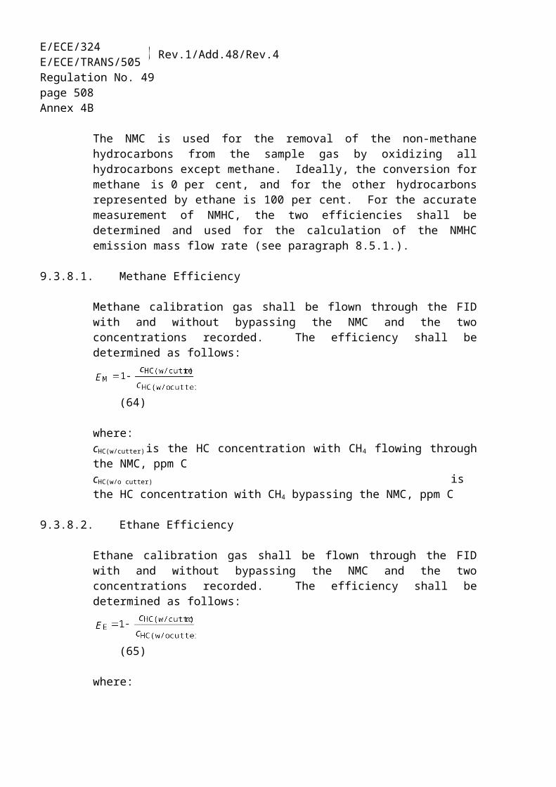
E/ECE/324E/ECE/TRANS/505 Rev.1/Add.48/Rev.4
Regulation No. 49page 508Annex 9B – Appendix 4
Approval of an OBD system as member of a certified emission OBD family
- List of the engine families concerned by the emission OBD family (when applicable, see paragraph 6.1.)
- Type 11/ of the parent engine system within the emission OBD family
- List of the engine types 11/ within the emission OBD family- Name of the engine system family concerned by the new OBD
system (when applicable)- Type 11/ of the engine system concerned by the new OBD system - Extended OBD description (issued by the manufacturer): reference
and date
. . . .
. . . .
. . . .
. . . .
. . . .
. . . .
Extension to include a new engine system into an emission OBD family- List (extended if necessary) of the engine families concerned by the
emission OBD family (when applicable, see paragraph 6.1.)- List (extended if necessary) of the engine types 11/ within the
emission OBD family- Actualised (new or unchanged) type 11/ of the parent engine system
within the emission OBD family- Extended OBD description (issued by the manufacturer): reference
and date
. . . .
. . . .
. . . .
. . . .
Extension to address a design change that affects the OBD system- List of the engine families (when applicable) concerned by the
design change- List of the engine types 11/ concerned by the design change- Actualised (when applicable, new or unchanged) type 11/ of the
parent engine system within the emission OBD family- Modified OBD description (issued by the manufacturer): reference
and date
. . . .
. . . .
. . . .
. . . .
Extension to address a malfunction reclassification- List of the engine families (when applicable) concerned by the
reclassification- List of the engine types 11/ concerned by the reclassification- Modified OBD description (issued by the manufacturer): reference
and date
. . . .
. . . .
. . . .

ECE/TR
AN
S/WP.29/2007/26
page 487
E/ECE/324E/ECE/TRANS/505 Rev.1/Add.48/Rev.4
Regulation No. 49page 509Annex 9B – Appendix 4
Item 2 to the technical compliance report (example) -
INFORMATION CONCERNING THE CONFORMITY OF THE OBD SYSTEM
1. Documentation package
The elements provided by the manufacturer in the documentation package of the emission OBD family, is complete and complies with the requirements of paragraph 8. of this annex, on the following issues:- documentation associated with each monitored component or system- documentation associated with each DTC- documentation associated with the malfunction classification - documentation associated with the emission OBD family
YES / NOYES / NOYES / NOYES / NO
The documentation required in paragraph 8.2. of this annex for installing an OBD system in a vehicle has been provided by the manufacturer in the documentation package, is complete, and complies with the requirements of this annex: YES / NOThe installation of the engine system equipped with the OBD system complies with Appendix 1 of this annex: YES / NO
2. Content of the documentation
MonitoringThe monitors comply with the requirements of paragraph 4.2. of this annex: YES / NO
ClassificationThe malfunction classification complies with the requirements of paragraph 4.5. of this annex: YES / NO
MI activation schemeAccording to paragraph 4.6.3. of this annex, the MI-activation scheme is:
The activation and the extinguishing of the malfunction indicator comply with the requirements of paragraph 4.6. of this annex:
Discriminatory /Non-discriminatory
YES / NO
DTCs recording & erasingThe recording and erasing of DTCs comply with the requirements of paragraphs 4.3. and 4.4. of this annex: YES / NO
Disablement of the OBD system

E/ECE/324E/ECE/TRANS/505 Rev.1/Add.48/Rev.4
Regulation No. 49page 510Annex 9B – Appendix 4
The strategies described in the documentation package for a momentary disconnection or disablement of the OBD system comply with the requirements of paragraph 5.2. of this annex YES / NO
Electronic system securityThe measures described by the manufacturer for electronic system security comply with the requirements of paragraph 4.8. of this annex
YES / NO

ECE/TR
AN
S/WP.29/2007/26
page 487
E/ECE/324E/ECE/TRANS/505 Rev.1/Add.48/Rev.4
Regulation No. 49page 511Annex 9B – Appendix 4
Item 3 to the technical compliance report (example)
INFORMATION CONCERNING DEFICIENCIES
Number of deficiencies of OBD system (ex: 4 deficiencies)The deficiencies comply with the requirements of paragraph 6.4. of this annex YES / NODeficiency No. 1 - Object of the deficiency
- Period of the deficiency
e.g. measuring of the Urea concentration (SCR) within defined tolerances
e.g. one year / six months after the date of approval
- (Description of deficiencies 2 to n-1)
Deficiency No. n - Object of the deficiency
- Period of the deficiency
e.g. measuring of NH3 concentration behind SCR system
e.g. one year / six months after the date of approval

E/ECE/324E/ECE/TRANS/505 Rev.1/Add.48/Rev.4
Regulation No. 49page 512Annex 9B – Appendix 4
Item 4 to the technical compliance report (example)
DEMONSTRATION TESTS OF THE OBD SYSTEM
1. Test result of the OBD system
Results of the testsThe OBD system described in the above complying documentation package has been tested with success according to Paragraph 6 of this annex for demonstrating the compliance of monitors and of malfunction classifications as listed in item 5:
YES / NO
Details to the conducted demonstration tests are given in item 5.
1.1. OBD system tested on the engine test-bed
Engine- Engine name (manufacturer and commercial names):- Engine type (as reported in the approval document):- Engine number (serial number):
. . . .
. . . .
. . . .
Control units concerned by this annex (incl. engine ECUs)- Main functionality:- Identification number (software and calibration): . . . .
. . . .
Diagnostic tool (scan tool used during testing)- Manufacturer:- Type:- Software / version
. . . .
. . . .
. . . .
Test information- Ambient testing conditions (temperature, humidity,
pressure):- Place of test (incl. altitude):- Testing fuel:- Engine lubricating oil:- Date of test:
. . . .
. . . .
. . . .
. . . .
. . . .

ECE/TR
AN
S/WP.29/2007/26
page 487
E/ECE/324E/ECE/TRANS/505 Rev.1/Add.48/Rev.4
Regulation No. 49page 513Annex 9B – Appendix 4
2. Demonstration tests of the installation of the OBD system
In addition to the demonstration of the OBD system / emission OBD family, the installation of the OBD system / of the OBD systems within the emission OBD family has been tested on a vehicle, according to the provisions of Appendix 1 of the referenced annex: YES / NO
2.1. Test result of the installation of the OBD system
Results of the testIf the installation of the OBD system has been tested on a vehicle, the installation of the OBD system has been tested with success according to Appendix 1 to the referenced annex YES / NO
2.2. Tested installation
If the installation of the OBD system has been tested on a vehicle:Tested vehicle- Vehicle name (manufacturer and commercial names):- Vehicle type:- Vehicle Identification Number (VIN):
. . . .
. . . .
. . . .
Diagnostic tool (scan tool used for testing)- Manufacturer:- Type:- Software / version:
. . .. . . .. . . .
Test information- Place and date: . . . .

E/ECE/324 – E/EC
E/TRA
NS/505) R
ev.1/Add.48/R
ev.4R
egulation No. 49
page 514A
nnex 9B – A
ppendix 4
Item 5 to the technical compliance report (example) TEST PROTOCOL

E/ECE/324 )
E/ECE/TR
AN
S/505 ) Rev.1/A
dd.48/Rev.4
page 519A
nnex 9B – A
ppendix 4E/ECE/324E/ECE/TRANS/505 Rev.1/Add.48/Rev.4
Regulation No. 49page 515Annex 9B – Appendix 5
Annex 9B - Appendix 5
FREEZE FRAME AND DATA STREAM INFORMATION
The following tables list the pieces of information that are considered in paragraphs 4.7.1.4. and 4.7.2. of this annex.
Table 1: MANDATORY REQUIREMENTS:
Freeze frame Data streamCalculated load (engine torque as a percentage of maximum torque available at the current engine speed)
x x
Engine speed x xEngine coolant temperature (or equivalent) x xBarometric pressure (directly measured or estimated) x x
Table 2: OPTIONAL ENGINE SPEED AND LOAD INFORMATION:
Freeze frame Data streamdriver’s demand engine torque (as a percentage of maximum engine torque)
x x
actual engine torque (calculated as a percentage of maximum engine torque, e.g. calculated from commanded injection fuel quantity)
x x
reference engine maximum torque xreference maximum engine torque as a function of engine speed
x
time elapsed since engine start x x
Table 3: OPTIONAL INFORMATION, IF USED BY THE EMISSION OR THE OBD SYSTEM TO ENABLE OR DISABLE ANY OBD INFORMATION
Freeze frame Data streamfuel level x xEngine oil temperature x xvehicle speed x xengine control computer system voltage (for the main control chip)
x x

ECE/TR
AN
S/WP.29/2007/26
page 516
E/ECE/324E/ECE/TRANS/505 Rev.1/Add.48/Rev.4
Regulation No. 49page 516Annex 9B – Appendix 5
Table 4: OPTIONAL INFORMATION, IF THE ENGINE IS SO EQUIPPED, SENSES OR CALCULATES THE INFORMATION:
Freeze frame Data stream
Absolute throttle position / intake air throttle position (position of valve used to regulate intake air)
x x
Diesel fuel control system status in case of a close loop system (e.g. in case of a fuel pressure close loop system)
x x
Fuel rail pressure x xInjection control pressure (i.e. pressure of the fluid controlling fuel injection) x xRepresentative fuel injection timing (beginning of first main injection) x xCommanded fuel rail pressure, x xCommanded injection control pressure (i.e. pressure of the fluid controlling fuel injection)
x x
Intake air temperature x xAmbient air temperature x xTurbocharger inlet / outlet air temperature (compressor and turbine) x xTurbocharger inlet / outlet pressure(compressor and turbine) x xCharge air temperature (post intercooler if fitted) x xActual boost pressure x xAir flow rate from mass air flow sensor x xCommanded EGR valve duty cycle/position, (provided EGR is so controlled) x xActual EGR valve duty cycle/position x xPTO status (active or not active) x xAccelerator pedal position x xRedundant absolute pedal position x if sensedInstantaneous fuel consumption x xCommanded/target boost pressure (if boost pressure used to control turbo operation)
x x
DPF inlet pressure x xDPF outlet pressure x xDPF delta pressure x xEngine-out exhaust pressure x xDPF inlet temperature x xDPF outlet temperature x xEngine-out exhaust gas temperature x xTurbocharger/turbine speed x xVariable geometry turbo position x xCommanded variable geometry turbo position x xWastegate valve position x xAir/fuel ratio sensor output xOxygen sensor output xNOx sensor output x

E/ECE/324 )
E/ECE/TR
AN
S/505 ) Rev.1/A
dd.48/Rev.4
page 519A
nnex 9B – A
ppendix 4E/ECE/324E/ECE/TRANS/505 Rev.1/Add.48/Rev.4
Regulation No. 49page 517Annex 9B – Appendix 6
Annex 9B - Appendix 6
REFERENCE STANDARD DOCUMENTS
This appendix contains the references to the industry standards that are to be used in accordance to the provisions in this annex to provide the serial communications interface to the vehicle/engine. There are three allowed solutions identified, ISO 15765-4 or SAE J1939-73 or ISO/PAS 27145. In addition there are other ISO or SAE standards that are applicable in accordance to the provisions in this annex.
ISO 15765-4 and those specifications included by reference therein to accomplish the WWH-OBD requirements. ISO 15765-4 "Road vehicles - Diagnostics on Controller Area Network (CAN) - Part 4: Requirements for emissions-related systems", dated on year 2006.
SAE J1939-73 and those specifications included by reference therein to accomplish the WWH-OBD requirements.J1939-73 "APPLICATION LAYER - DIAGNOSTICS", dated on year 2006.
ISO/PAS 27145 and those specifications included by reference therein to accomplish the WWH-OBD requirements.
(i) ISO/PAS 27145-1:2006 Road vehicles - On board diagnostics (WWH-OBD) implementation - Part 1 - General Information and use case definitions
(ii) ISO/PAS 27145-2:2006 Road vehicles – Implementation of WWH-OBD communication requirements - Part 2 - Common emissions-related data dictionary;
(iii) ISO/PAS 27145-3:2006 Road vehicles – Implementation of WWH-OBD communication requirements - Part 3 - Common message dictionary;
(iv) ISO/PAS 27145-4:2006 Road vehicles – Implementation of WWH-OBD communication requirements - Part 4 - Connection between vehicle and test equipment;
The following International Organization of Standards (ISO) documents are incorporated by reference into this Regulation:ISO 15031-3:2004 "Road vehicles — Communication between vehicle and external equipment for emissions-related diagnostics — Part 3: Diagnostic connector and related electrical circuits, specification and use".
The following Society of Automotive Engineers (SAE) (ISO) documents are incorporated by reference into this Regulation:SAE J2403 "Medium/Heavy-Duty E/E Systems Diagnosis Nomenclature", dated on August 2004.SAE J1939-13 "Off-Board Diagnostic Connector", dated on March 2004.
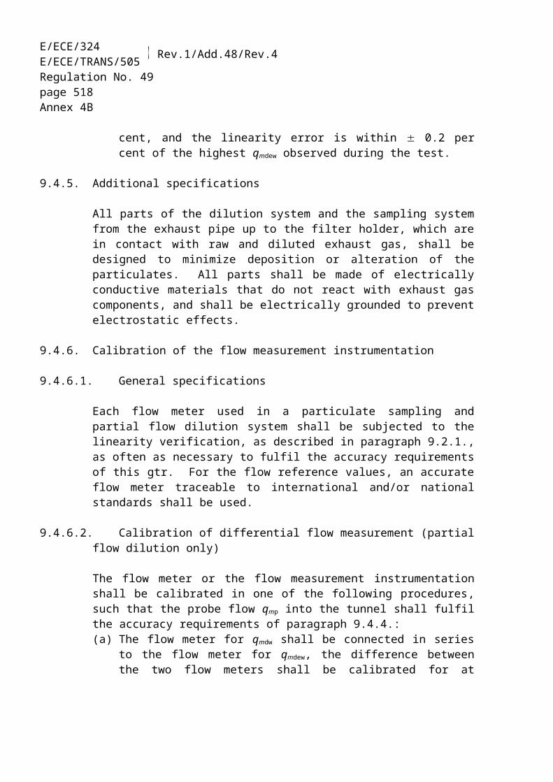
ECE/TR
AN
S/WP.29/2007/26
page 520
E/ECE/324E/ECE/TRANS/505 Rev.1/Add.48/Rev.4
Regulation No. 49page 518Annex 9B – Appendix 7
Annex 9B - Appendix 7
DOCUMENTATION REGARDING OBD RELATED INFORMATION
The OBD related information requested by this appendix shall be provided by the vehicle manufacturer for the purposes of enabling the manufacture of OBD-compatible replacement or service parts and diagnostic tools and test equipment in the manner prescribed in the main part of this Regulation.
REPLACEMENT PARTS, DIAGNOSTIC TOOLS AND TEST EQUIPMENT
The information shall enable manufacturers of replacement or retrofit components to make the parts they manufacture compatible with the OBD system with a view to fault-free operation assuring the vehicle user against malfunctions. Similarly, such relevant information shall enable the manufacturers of diagnostic tools and test equipment to make tools and equipment that provide for effective and accurate diagnosis of emission control systems.
In the case of replacement or service components, information can only be requested for such components that are subject to type-approval, or for components that form part of a system that is subject to type-approval.
The request for information must identify the exact specification of the engine model type/engine model type within an engine family for which the information is required. It must confirm that the information is required for the development of replacement or retrofit parts or components or diagnostic tools or test equipment.
REPAIR INFORMATION
No later than three months after the manufacturer has provided any authorised dealer or repair shop with repair information, the manufacturer shall make that information (including all subsequent amendments and supplements) available upon reasonable and non-discriminatory payment.
The manufacturer must also make accessible, where appropriate upon payment the technical information required for the repair or maintenance of motor vehicles unless that information is covered by an intellectual property right or constitutes essential, secret know-how which is identified in an appropriate form; in such case, the necessary technical information must not be withheld improperly.
Entitled to such information is any person engaged in commercially servicing or repairing, road-side rescuing, inspecting or testing of vehicles or in manufacturing or selling replacement or retro-fit components, diagnostic tools and test equipment.

E/ECE/324 )
E/ECE/TR
AN
S/505 ) Rev.1/A
dd.48/Rev.4
page 519A
nnex 9B – A
ppendix 4E/ECE/324E/ECE/TRANS/505 Rev.1/Add.48/Rev.4
Regulation No. 49page 519Annex 9B – Appendix 7
In the event of failure to comply with these provisions the Approval Authority shall take appropriate measures to ensure that repair information is available, in accordance with the procedures laid down for type-approval and in-service surveys.
-----