Encoders Decoders Example of using decoders with MUX Conclusion.
date post
21-Dec-2015Category
view
222download
0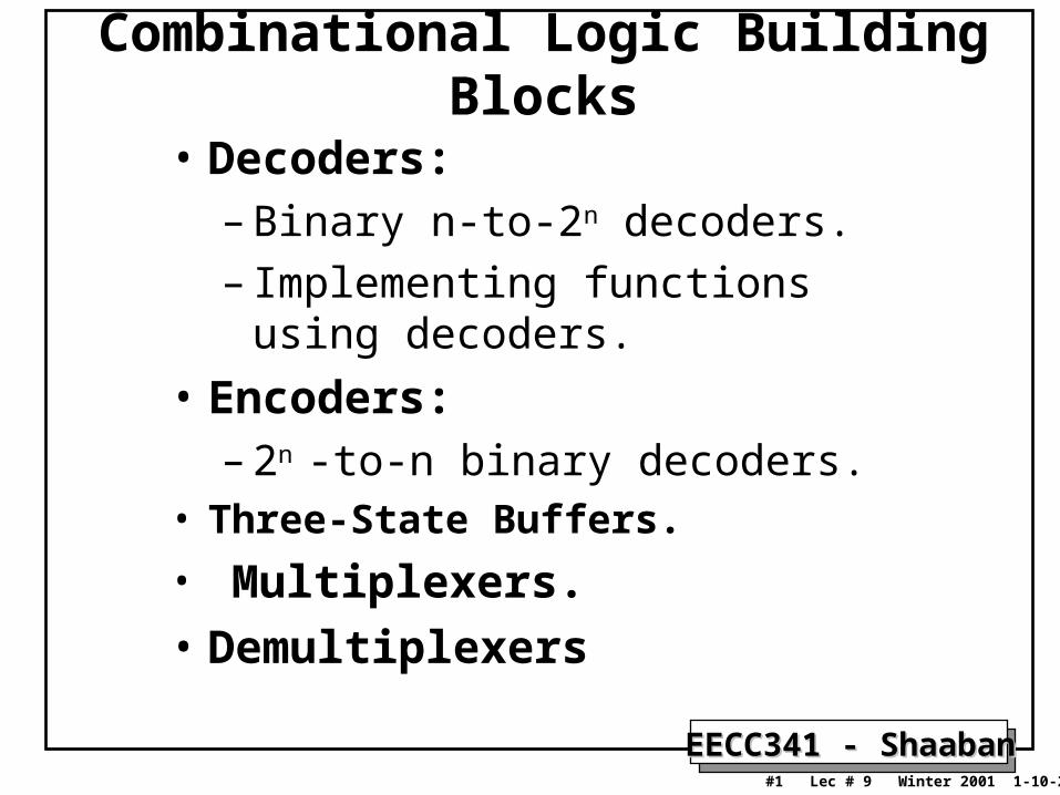
EECC341 - ShaabanEECC341 - Shaaban#1 Lec # 9 Winter 2001 1-10-2002
Combinational Logic Building Blocks
• Decoders:– Binary n-to-2n decoders.
– Implementing functions using decoders.
• Encoders:– 2n -to-n binary decoders.
• Three-State Buffers.
• Multiplexers.
• Demultiplexers
EECC341 - ShaabanEECC341 - Shaaban#2 Lec # 9 Winter 2001 1-10-2002
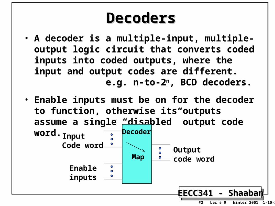
DecodersDecoders• A decoder is a multiple-input, multiple-output logic
circuit that converts coded inputs into coded outputs, where the input and output codes are different. e.g. n-to-2n, BCD decoders.
• Enable inputs must be on for the decoder to function, otherwise its outputs assume a single “disabled” output code word.
Decoder
Map
InputCode word
Enableinputs
Output code word
EECC341 - ShaabanEECC341 - Shaaban#3 Lec # 9 Winter 2001 1-10-2002
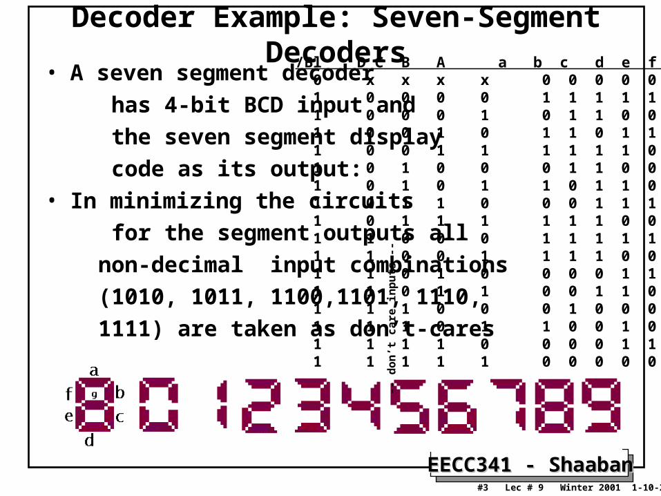
Decoder Example: Seven-Segment Decoders• A seven segment decoder
has 4-bit BCD input and
the seven segment display
code as its output:
• In minimizing the circuits
for the segment outputs all
non-decimal input combinations
(1010, 1011, 1100,1101, 1110,
1111) are taken as don’t-cares
/Bl D C B A a b c d e f g 0 x x x x 0 0 0 0 0 0 0 1 0 0 0 0 1 1 1 1 1 1 0 1 0 0 0 1 0 1 1 0 0 0 0 1 0 0 1 0 1 1 0 1 1 0 1 1 0 0 1 1 1 1 1 1 0 0 1 1 0 1 0 0 0 1 1 0 0 1 1 1 0 1 0 1 1 0 1 1 0 1 1 1 0 1 1 0 0 0 1 1 1 1 1 1 0 1 1 1 1 1 1 0 0 0 0 1 1 0 0 0 1 1 1 1 1 1 1 1 1 0 0 1 1 1 1 0 0 1 1 1 1 0 1 0 0 0 0 1 1 0 1 1 1 0 1 1 0 0 1 1 0 0 1 1 1 1 0 0 0 1 0 0 0 1 1 1 1 1 0 1 1 0 0 1 0 1 1 1 1 1 1 0 0 0 0 1 1 1 1 1 1 1 1 1 0 0 0 0 0 0 0
-- d
on’t
car
e in
pu
ts -
-
EECC341 - ShaabanEECC341 - Shaaban#4 Lec # 9 Winter 2001 1-10-2002
Binary n-to-2Binary n-to-2nn Decoders Decoders
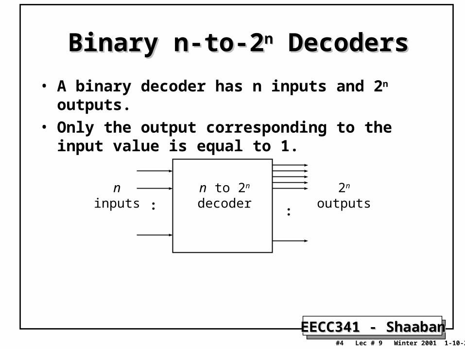
• A binary decoder has n inputs and 2n outputs.
• Only the output corresponding to the input value is equal to 1.
: :
ninputs
n to 2n
decoder2n
outputs
EECC341 - ShaabanEECC341 - Shaaban#5 Lec # 9 Winter 2001 1-10-2002
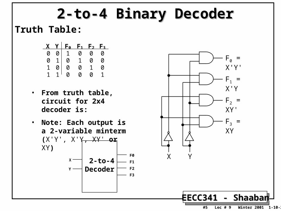
2-to-4 Binary Decoder2-to-4 Binary Decoder
• From truth table, circuit for 2x4 decoder is:
• Note: Each output is a 2-variable minterm (X'Y', X'Y, XY' or XY)
X Y F0 F1 F2 F3
0 0 1 0 0 00 1 0 1 0 01 0 0 0 1 01 1 0 0 0 1
F0 = X'Y'
F1 = X'Y
F2 = XY'
F3 = XY
X Y
Truth Table:
2-to-4Decoder
X
Y
F0
F1
F2
F3
EECC341 - ShaabanEECC341 - Shaaban#6 Lec # 9 Winter 2001 1-10-2002
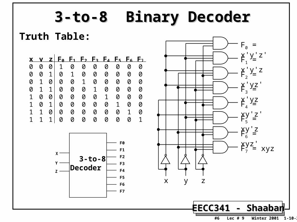
3-to-8 Binary Decoder3-to-8 Binary Decoder
x y z F0 F1 F2 F3 F4 F5 F6 F7
0 0 0 1 0 0 0 0 0 0 00 0 1 0 1 0 0 0 0 0 00 1 0 0 0 1 0 0 0 0 00 1 1 0 0 0 1 0 0 0 01 0 0 0 0 0 0 1 0 0 01 0 1 0 0 0 0 0 1 0 01 1 0 0 0 0 0 0 0 1 01 1 1 0 0 0 0 0 0 0 1
F1 = x'y'z
x zy
F0 = x'y'z'
F2 = x'yz'
F3 = x'yz
F5 = xy'z
F4 = xy'z'
F6 = xyz'
F7 = xyz
Truth Table:
3-to-8Decoder
X
Y
F0
F1
F2
F3
F4
F5
F6
F7
Z
EECC341 - ShaabanEECC341 - Shaaban#7 Lec # 9 Winter 2001 1-10-2002
Implementing Functions Using Decoders
• Any n-variable logic function, in canonical sum-of-minterms form can be implemented using a single n-to-2n decoder to generate the minterms, and an OR gate to form the sum.
– The output lines of the decoder corresponding to the minterms of the function are used as inputs to the or gate.
• Any combinational circuit with n inputs and m outputs can be implemented with an n-to-2n decoder with m OR gates.
• Suitable when a circuit has many outputs, and each output function is expressed with few minterms.

EECC341 - ShaabanEECC341 - Shaaban#8 Lec # 9 Winter 2001 1-10-2002
Implementing Functions Using Decoders
• Example: Full adder
S(x, y, z) = (1,2,4,7)
C(x, y, z) = (3,5,6,7)
3-to-8Decoder
S2
S1
S0
x
y
z
0
1
2
3
4
5
6
7
S
C
x y z C S0 0 0 0 00 0 1 0 10 1 0 0 10 1 1 1 01 0 0 0 11 0 1 1 01 1 0 1 01 1 1 1 1
EECC341 - ShaabanEECC341 - Shaaban#9 Lec # 9 Winter 2001 1-10-2002
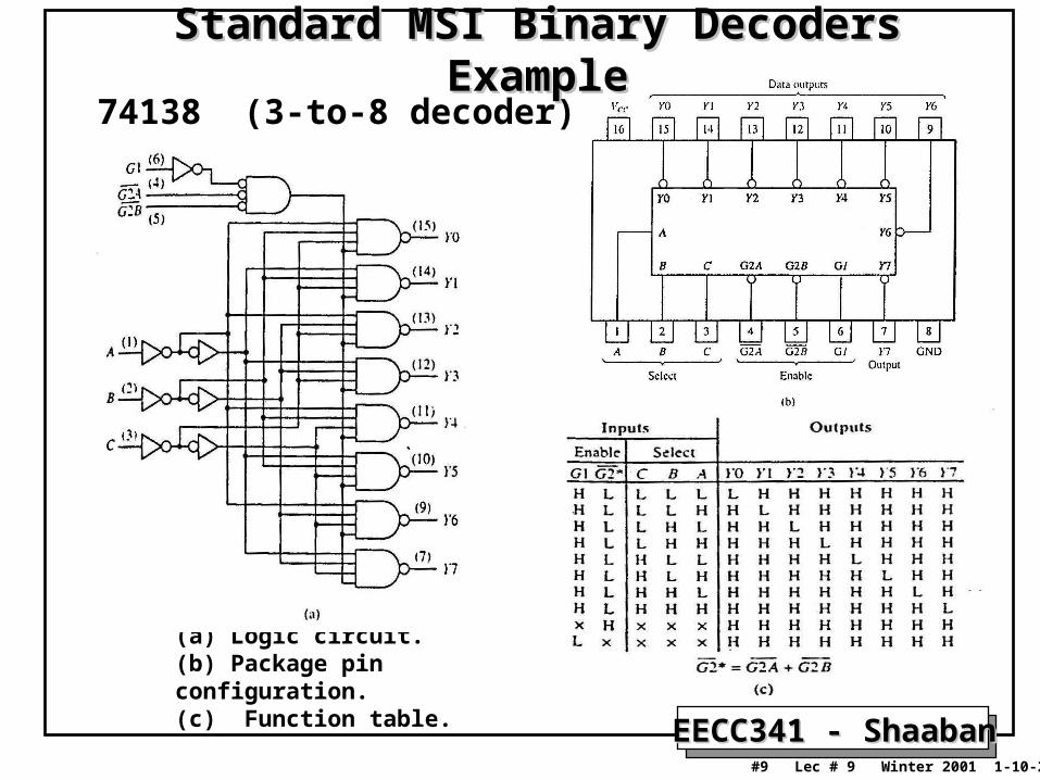
Standard MSI Binary Decoders ExampleStandard MSI Binary Decoders Example
74138 (3-to-8 decoder)
(a) Logic circuit. (b) Package pin configuration. (c) Function table.
EECC341 - ShaabanEECC341 - Shaaban#10 Lec # 9 Winter 2001 1-10-2002
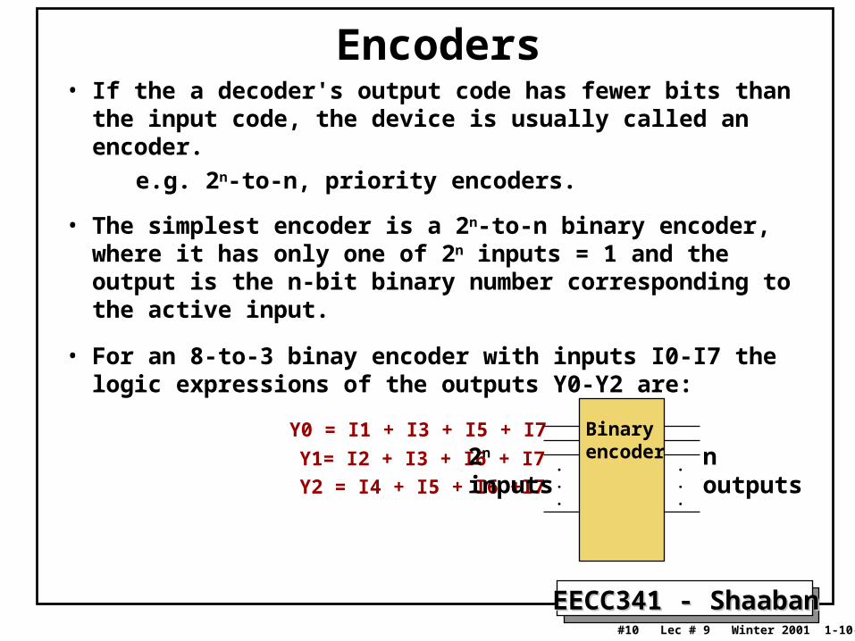
Encoders• If the a decoder's output code has fewer bits than the input
code, the device is usually called an encoder.
e.g. 2n-to-n, priority encoders.
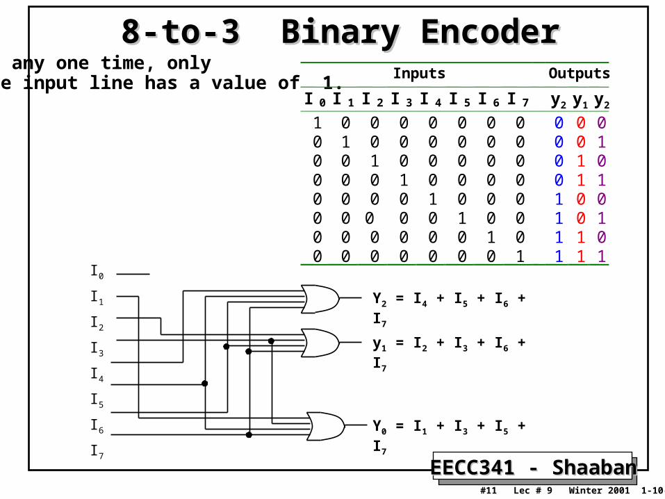
• The simplest encoder is a 2n-to-n binary encoder, where it has only one of 2n inputs = 1 and the output is the n-bit binary number corresponding to the active input.
• For an 8-to-3 binay encoder with inputs I0-I7 the logic expressions of the outputs Y0-Y2 are:
Y0 = I1 + I3 + I5 + I7
Y1= I2 + I3 + I6 + I7
Y2 = I4 + I5 + I6 +I7
.
.
.
.
.
.
2n
inputsn outputs
Binaryencoder
EECC341 - ShaabanEECC341 - Shaaban#11 Lec # 9 Winter 2001 1-10-2002
8-to-3 Binary Encoder8-to-3 Binary EncoderAt any one time, only one input line has a value of 1.
Inputs Outputs
I 0 I 1 I 2 I 3 I 4 I 5 I 6 I 7 y2 y1 y2
1 0 0 0 0 0 0 0 0 0 00 1 0 0 0 0 0 0 0 0 10 0 1 0 0 0 0 0 0 1 00 0 0 1 0 0 0 0 0 1 10 0 0 0 1 0 0 0 1 0 00 0 0 0 0 1 0 0 1 0 10 0 0 0 0 0 1 0 1 1 00 0 0 0 0 0 0 1 1 1 1
I0
I1
I2
I3
I4
I5
I6
I7
Y0 = I1 + I3 + I5 + I7
y1 = I2 + I3 + I6 + I7
Y2 = I4 + I5 + I6 + I7
EECC341 - ShaabanEECC341 - Shaaban#12 Lec # 9 Winter 2001 1-10-2002
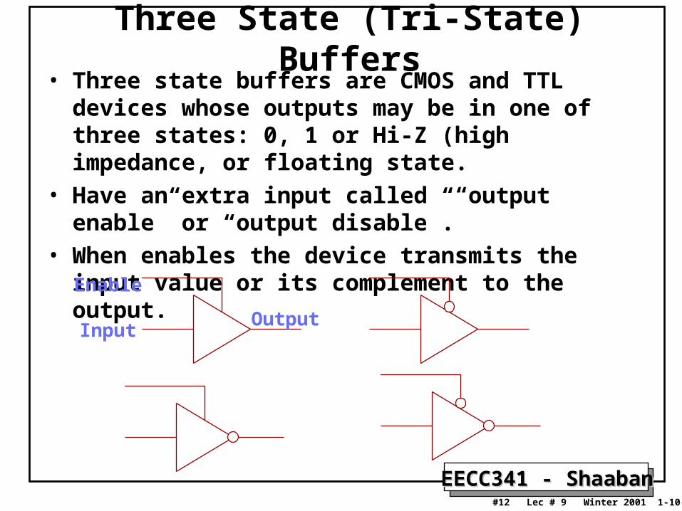
Three State (Tri-State) Buffers• Three state buffers are CMOS and TTL devices whose
outputs may be in one of three states: 0, 1 or Hi-Z (high impedance, or floating state.
• Have an extra input called “output enable” or “output disable”.
• When enables the device transmits the input value or its complement to the output.Enable
InputOutput
EECC341 - ShaabanEECC341 - Shaaban#13 Lec # 9 Winter 2001 1-10-2002
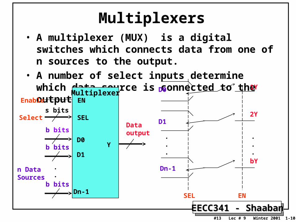
Multiplexers• A multiplexer (MUX) is a digital switches which
connects data from one of n sources to the output.
• A number of select inputs determine which data source is connected to the output.
Multiplexer
b bits
b bits
b bits
.
.
Dataoutput
n DataSources
s bitsSelect
Enable EN
SEL
D0
D1
Dn-1
Y
EN
.
.
.
D0
D1
Dn-1
.
.
.
1Y
2Y
bY
SEL
EECC341 - ShaabanEECC341 - Shaaban#14 Lec # 9 Winter 2001 1-10-2002
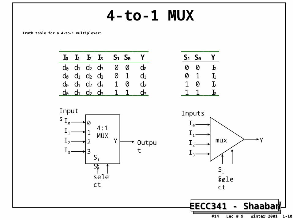
4-to-1 MUXTruth table for a 4-to-1 multiplexer:
mux Y
Inputs
select
S1 S0
I0
I1
I2
I3
I0 I1 I2 I3 S1 S0 Y
d0 d1 d2 d3 0 0 d0
d0 d1 d2 d3 0 1 d1
d0 d1 d2 d3 1 0 d2
d0 d1 d2 d3 1 1 d3
S1 S0 Y
0 0 I0
0 1 I1
1 0 I2
1 1 I3
4:1MUX
Y
Inputs
select
S1 S0
I0
I1
I2
I3
0
1
2
3Output
EECC341 - ShaabanEECC341 - Shaaban#15 Lec # 9 Winter 2001 1-10-2002
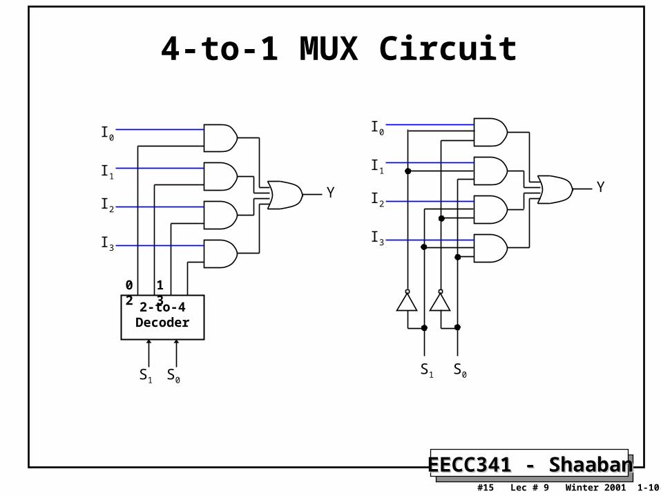
4-to-1 MUX Circuit
S1 S0
0 1 2 3
2-to-4 Decoder
I0
I1
I2
I3
Y
S1 S0
I0
I1
I2
I3
Y
EECC341 - ShaabanEECC341 - Shaaban#16 Lec # 9 Winter 2001 1-10-2002
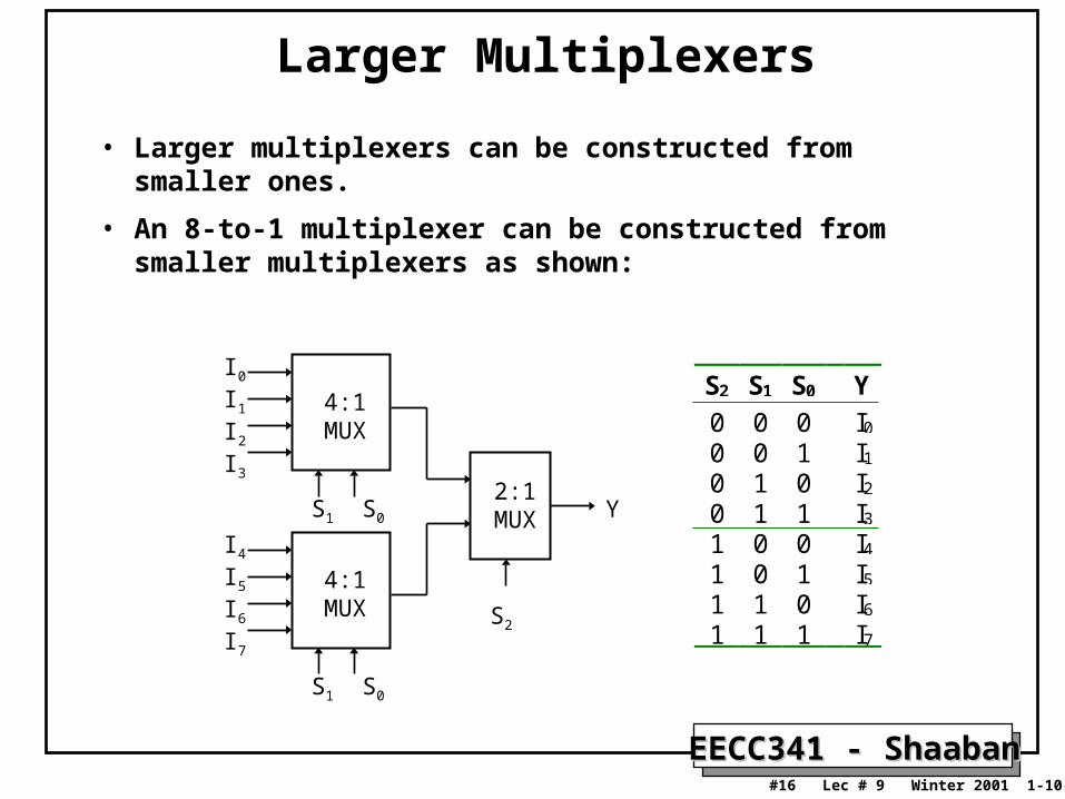
Larger Multiplexers
• Larger multiplexers can be constructed from smaller ones.
• An 8-to-1 multiplexer can be constructed from smaller multiplexers as shown:
4:1 MUX
I0
I1
I2
I3
S1 S0
4:1 MUX
I4
I5
I6
I7
S1 S0
2:1 MUX
S2
Y
S2 S1 S0 Y
0 0 0 I0
0 0 1 I1
0 1 0 I2
0 1 1 I3
1 0 0 I4
1 0 1 I5
1 1 0 I6
1 1 1 I7
EECC341 - ShaabanEECC341 - Shaaban#17 Lec # 9 Winter 2001 1-10-2002
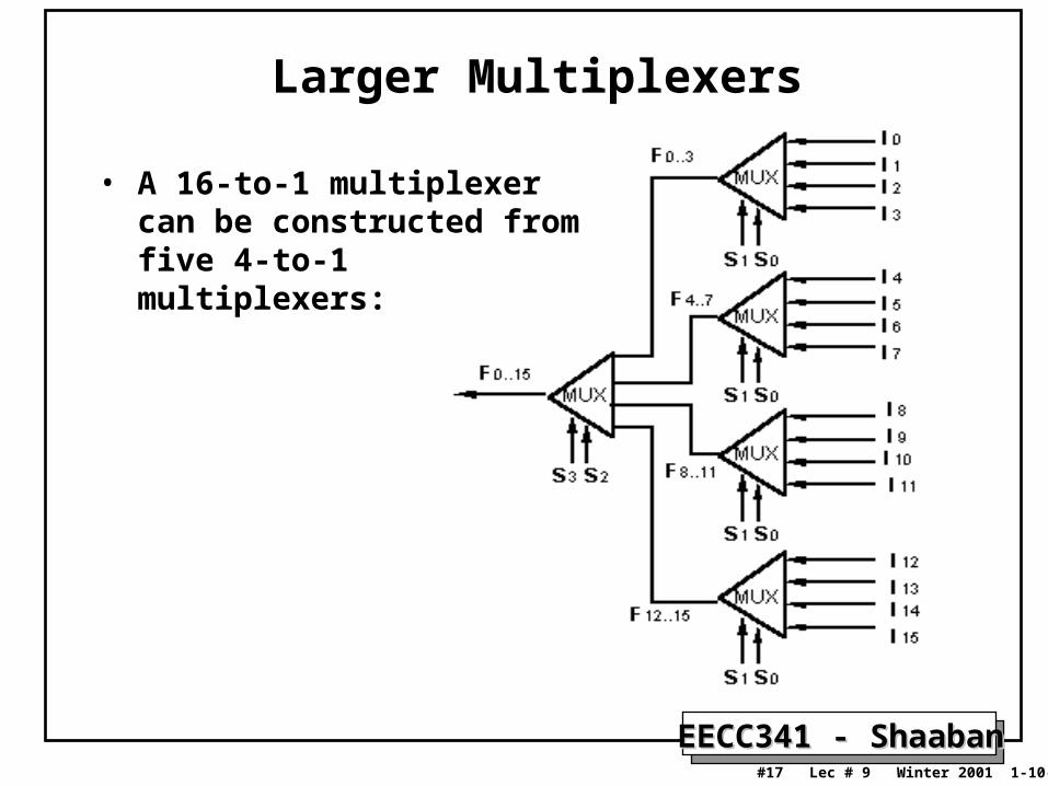
Larger Multiplexers
• A 16-to-1 multiplexer can be constructed from five 4-to-1 multiplexers:
EECC341 - ShaabanEECC341 - Shaaban#18 Lec # 9 Winter 2001 1-10-2002
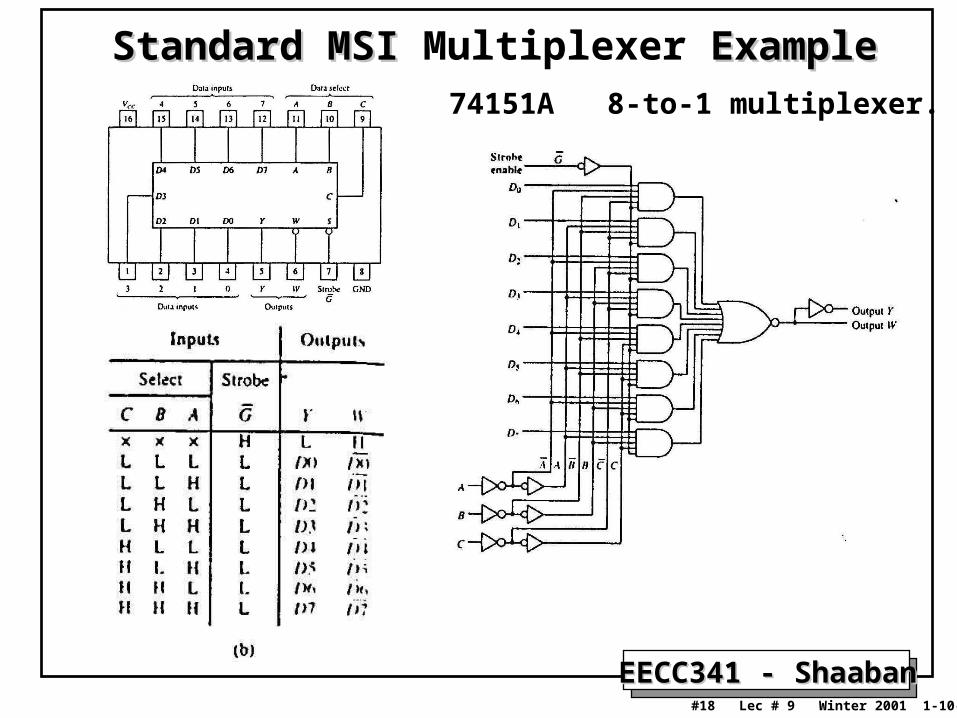
Standard MSI Standard MSI Multiplexer ExampleExample74151A 8-to-1 multiplexer.
EECC341 - ShaabanEECC341 - Shaaban#19 Lec # 9 Winter 2001 1-10-2002
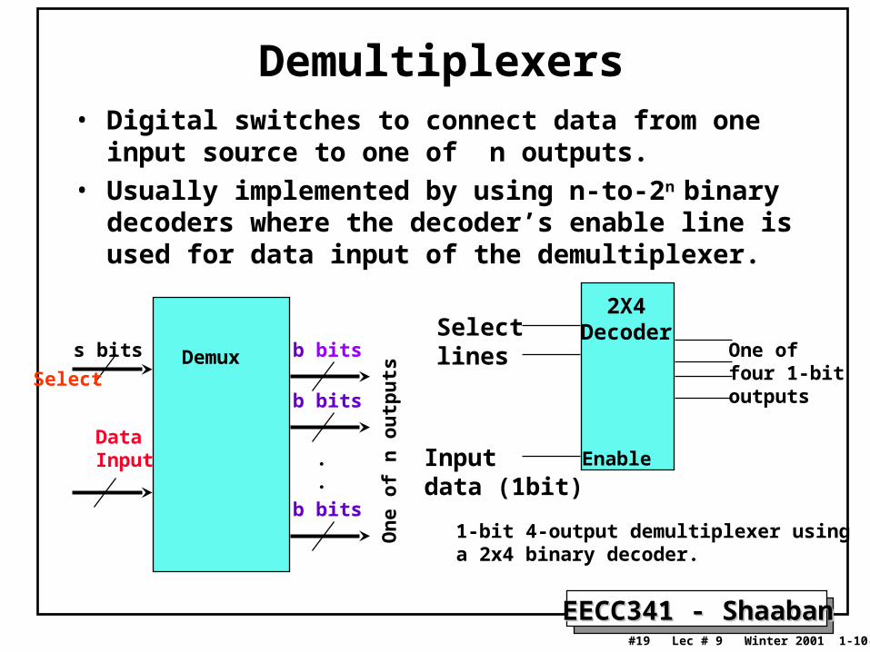
Demultiplexers• Digital switches to connect data from one input source to one
of n outputs.
• Usually implemented by using n-to-2n binary decoders where the decoder’s enable line is used for data input of the demultiplexer.
2X4DecoderSelect
lines
Inputdata (1bit)
Enable
One offour 1-bitoutputsOne of n
DataSourcesselected
s bits
Select
b bits
b bits
b bits
.
.
DataInput
Demux
On
e of
n o
utp
uts
1-bit 4-output demultiplexer using a 2x4 binary decoder.

EECC341 - ShaabanEECC341 - Shaaban#20 Lec # 9 Winter 2001 1-10-2002
1-to-4 Demultiplexer1-to-4 Demultiplexer
S1 So Y0 Y1 Y2 Y3
0 0 D 0 0 00 1 0 D 0 01 0 0 0 D 01 1 0 0 0 D
demuxData D
Outputs
select
S1 S0
Y0 = D.S1'.S0'
Y1 = D.S1'.S0
Y2 = D.S1.S0'
Y3 = D.S1.S0
2x4 Decoder
D
S1
S0
Y0 = D.S1'.S0'
Y1 = D.S1'.S0
Y2 = D.S1.S0'
Y3 = D.S1.S0E
EECC341 - ShaabanEECC341 - Shaaban#21 Lec # 9 Winter 2001 1-10-2002
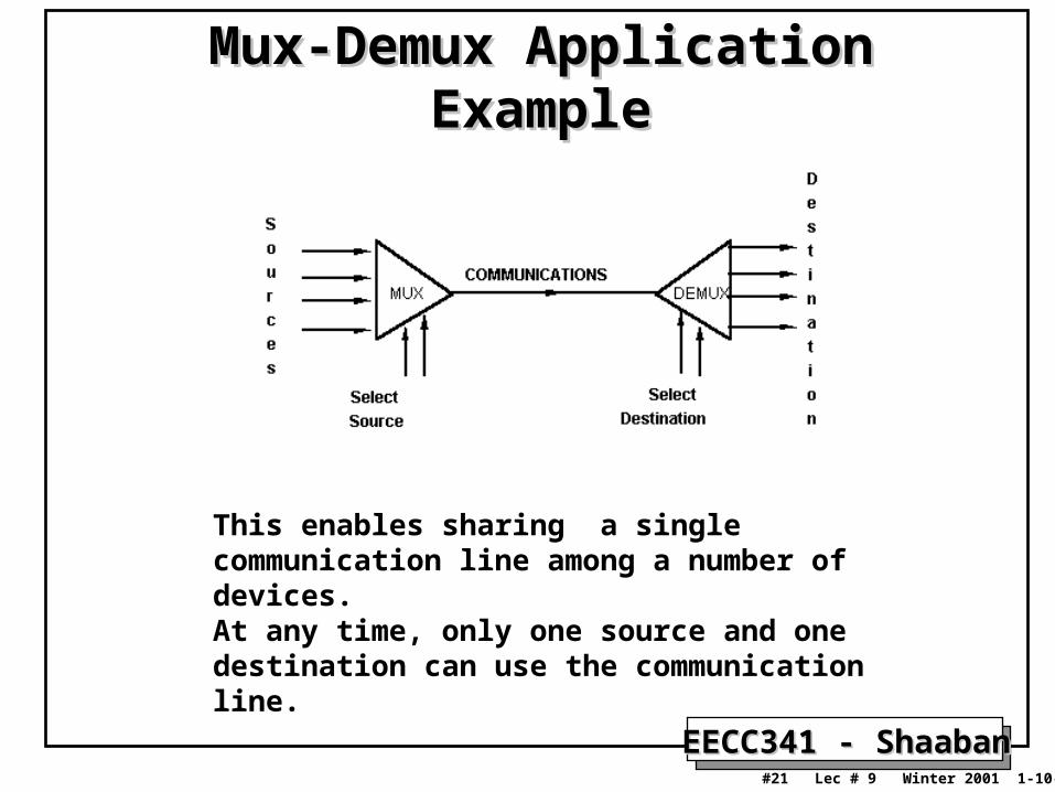
Mux-Demux Application ExampleMux-Demux Application Example
This enables sharing a single communication line among a number of devices.At any time, only one source and one destination can use the communication line.