
E—e Egie o e ew Euoea ige Aica - ASME...
11
THE AMERICAN SOCIETY OF MECHANICAL ENGINEERS 90-GT-119 345 E. 47 St., New York, N.Y. 10017 The Society shall not be responsible for statements or opinions advanced in papers or in dis- cussion at meetings of the Society or of its Divisions or Sections. or printed in its publications oc^) Discussion is printed only if the paper is published in an ASME Journal. Papers are available from ASME for fifteen months after the meeting. Printed in USA. EJ200—The Engine for the New European Fighter Aircraft R. J. LANE Chief Engineer - EJ200 J. BEHENNA Assistant Chief Engineer - EJ200 Rolls-Royce plc PO Box 3 Filton Bristol BS12 70E Abstract Europe has a European Staff Requirement (ESR) for a new fighter aircraft This paper describes the concept and design of the Agreement by the armament directors of 4 countries at Turin August 1985: EJ200 engine to meet the air staff targets for the - twin engined aircraft European Fighter Aircraft. - airframe mass 9.75 tonnes wing area 50 square metres The international collaborative arrangements to support - engine reheated thrust 90kN class the programme are shown and the lessons learnt from _ previous collaboration illustrated. Specified parameters The excellent progress made in the programme during performance cost the first year since the signing of the development - operational targets contract is described to illustrate confidence in the ability to meet the design targets within the programme Fig 1 Requirement timescales. Introduction The EJ200 Engine The EJ200 combat engine is being designed and developed as a direct result of the new European Fighter Aircraft ( EFA ) requirement. The European Fighter Aircraft is to be built and operated by the UK , Germany, Italy and Spain and will enter service in the second half of the 1990s. The paper also illustrates the great improvement in European capability for a sophisticated and technologically advanced project such as EJ200 and compares early progress with that made on the RB199 engine which is now a very successful engine in the Tornado project. Finally, the lessons learnt on the Tornado programme are shown to have been successfully applied with a consequent reduction in programme risk and timescales and costs. The air staff target to which the EFA is being designed Part calls for a high performance, high agility aircraft which is to be designed around a very low weight requirement Aircraft and Engine Concept and Organisation with excellent reliability and ease of maintainability as a major design feature (summarised in Figure 1). The EFA is a twin engine Canard Delta of compact size, very high performance and high agility in both sub-sonic This paper describes the engine concept and engine and supersonic flight conditions. solution which follows this requirement and describes the progress made in the programme after the first year It is powered by two EJ200 engines each of 90 Kn thrust since the signing of the development contract. class (20,000 lbs ) as shown in Figures 2 & 3. • Presented at the Gas Turbine and Aeroengine Congress and Exposition—June 11-14, 1990—Brussels, Belgium This paper has been accepted for publication in the Transactions of the ASME Discussion of it will be accepted at ASME Headquarters until September 30, 1990 Copyright © 1990 by ASME Downloaded From: http://ebooks.asmedigitalcollection.asme.org/ on 06/12/2018 Terms of Use: http://www.asme.org/about-asme/terms-of-use
Transcript of E—e Egie o e ew Euoea ige Aica - ASME...

THE AMERICAN SOCIETY OF MECHANICAL ENGINEERS 90-GT-119345 E. 47 St., New York, N.Y. 10017
The Society shall not be responsible for statements or opinions advanced in papers or in dis-cussion at meetings of the Society or of its Divisions or Sections. or printed in its publications
oc^)
Discussion is printed only if the paper is published in an ASME Journal. Papers are available from ASME for fifteen months after the meeting.
Printed in USA.
EJ200—The Engine for the New EuropeanFighter Aircraft
R. J. LANEChief Engineer - EJ200
J. BEHENNAAssistant Chief Engineer - EJ200
Rolls-Royce plcPO Box 3
FiltonBristol
BS12 70E
Abstract Europe has a European Staff Requirement (ESR) for a new fighter aircraft
This paper describes the concept and design of the Agreement by the armament directors of 4 countries at Turin August 1985:
EJ200 engine to meet the air staff targets for the- twin engined aircraft
European Fighter Aircraft. - airframe mass 9.75 tonneswing area 50 square metres
The international collaborative arrangements to support - engine reheated thrust 90kN classthe programme are shown and the lessons learnt from _previous collaboration illustrated. Specified parameters
The excellent progress made in the programme during performancecostthe first year since the signing of the development - operational targets
contract is described to illustrate confidence in the abilityto meet the design targets within the programme Fig 1 Requirementtimescales.
Introduction
The EJ200 Engine
The EJ200 combat engine is being designed anddeveloped as a direct result of the new European FighterAircraft ( EFA ) requirement.
The European Fighter Aircraft is to be built and operatedby the UK , Germany, Italy and Spain and will enterservice in the second half of the 1990s.
The paper also illustrates the great improvement inEuropean capability for a sophisticated andtechnologically advanced project such as EJ200 andcompares early progress with that made on the RB199engine which is now a very successful engine in theTornado project.
Finally, the lessons learnt on the Tornado programme areshown to have been successfully applied with aconsequent reduction in programme risk and timescalesand costs.
The air staff target to which the EFA is being designed Partcalls for a high performance, high agility aircraft which isto be designed around a very low weight requirement Aircraft and Engine Concept and Organisationwith excellent reliability and ease of maintainability as amajor design feature (summarised in Figure 1). The EFA is a twin engine Canard Delta of compact size,
very high performance and high agility in both sub-sonicThis paper describes the engine concept and engine and supersonic flight conditions.solution which follows this requirement and describes theprogress made in the programme after the first year It is powered by two EJ200 engines each of 90 Kn thrustsince the signing of the development contract. class (20,000 lbs ) as shown in Figures 2 & 3.
• Presented at the Gas Turbine and Aeroengine Congress and Exposition—June 11-14, 1990—Brussels, BelgiumThis paper has been accepted for publication in the Transactions of the ASME
Discussion of it will be accepted at ASME Headquarters until September 30, 1990
Copyright © 1990 by ASME
Downloaded From: http://ebooks.asmedigitalcollection.asme.org/ on 06/12/2018 Terms of Use: http://www.asme.org/about-asme/terms-of-use
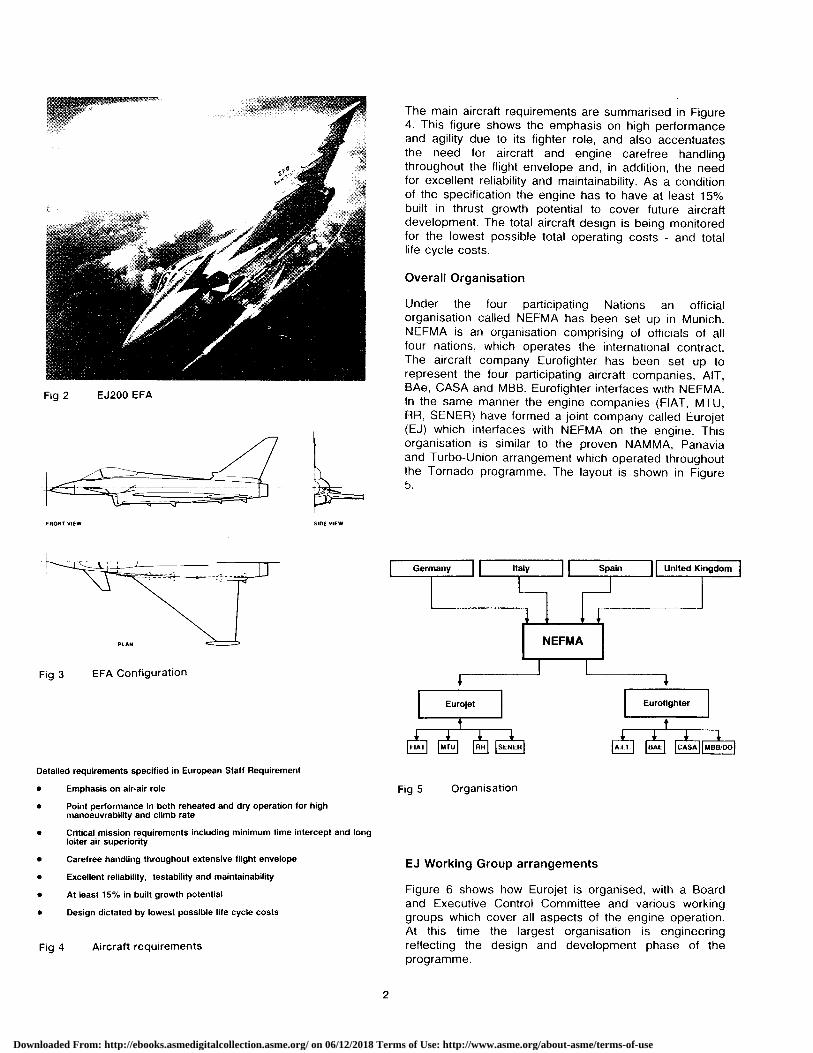
Fig 2 EJ200 EFA
The main aircraft requirements are summarised in FigureThis figure shows the emphasis on high performance
and agility due to its fighter role, and also accentuatesthe need for aircraft and engine carefree handlingthroughout the flight envelope and, in addition, the needfor excellent reliability and maintainability. As a conditionof the specification the engine has to have at least 15%built in thrust growth potential to cover future aircraftdevelopment. The total aircraft design is being monitoredfor the lowest possible total operating costs - and totallife cycle costs.
Overall Organisation
Under the four participating Nations an officialorganisation called NEFMA has been set up in Munich.NEFMA is an organisation comprising of officials of allfour nations, which operates the international contract.The aircraft company Eurofighter has been set up torepresent the four participating aircraft companies, AIT,BAe, CASA and MBB. Eurofighter interfaces with NEFMA.In the same manner the engine companies (FIAT, MTU,RR, SENER) have formed a joint company called Eurojet(EJ) which interfaces with NEFMA on the engine. Thisorganisation is similar to the proven NAMMA, Panaviaand Turbo-Union arrangement which operated throughoutthe Tornado programme. The layout is shown in Figure5.
FRONT VIEW SIOE VIEW
PLAN
Fig 3 EFA Configuration
Eurojet f Eurofighter
FIAT MTU RR SENER A.I.T. BAE CASA M88/DO
Detailed requirements specified in European Staff Requirement
• Emphasis on air-air role
• Point performance in both reheated and dry operation for highmanoeuvrability and climb rate
• Critical mission requirements including minimum time intercept and longloiter air superiority
• Carefree handling throughout extensive flight envelope
• Excellent reliability, testability and maintainability
• At least 15% in built growth potential
• Design dictated by lowest possible life cycle costs
Fig 4 Aircraft requirements
Fig 5 Organisation
EJ Working Group arrangements
Figure 6 shows how Eurojet is organised, with a Boardand Executive Control Committee and various workinggroups which cover all aspects of the engine operation.At this time the largest organisation is engineeringreflecting the design and development phase of theprogramme.
Downloaded From: http://ebooks.asmedigitalcollection.asme.org/ on 06/12/2018 Terms of Use: http://www.asme.org/about-asme/terms-of-use

0
40 50 60 70 80
SLS specific thrust (Rift off) Ns / Kg
InterceptionCFF 80%
90
Strike / InterdictionCFF 10%
RelativeAircraft
TOW
*10%
Shareholders Board12 members 3 from each
partner companyManaging Director
Executive ControlCommittee
MD+partner companyProgramme Directors
Working Groups
Marketing Production Commercial Engineering
Programme FinanceAssurance Support Management
Working Group structureChairman-Relevant full-time Eurojet staff member
Members -Responsible full-time manager—Fiat, MTU, Rolls-Royce, SENER
Fig 6 Eurojet Working Group Concept
The system is similar to that used for the RB199 in theTornado programme and, for instance, the engineeringworking group has comprehensive sub-groups whichcover all aspects of the engine development programmesuch as design, development, performance, mechanicaltechnology etc. Each working group has a formalrepresentative from each of the partners who participateas necessary. The system works very well and this isdue in no small part to the three Tornado programmecompanies who know each others ways and workingpractices and to a large extent operate in a similarmanner. The ease with which the decisions are madeand programmes agreed and carried out shows howeffective inter-European co-operation can be. Thesuccess will be illustrated later in the paper.
Part 2
Engine description
The EJ 200 engine concept requires a very compactlightweight configuration to fit within a closely cowledengine duct.
Fan Pressure Ratio
2.5 3.0 3.5 4.0 4.5
+20% l 1.5 1.0 0.5 0Typical Bypass Ratio at Constant Technology
Fig 7 Specific Thrust - Aircraft Mission Sensitivity
The priority on the air to air role dictated by theEuropean Staff Requirement leads to an emphasis on therequirement for low reheated s.f.c. levels. This isillustrated by Figure 7 which shows that for supersonicinterception mission some 80% of the fuel is used inCombat as opposed to 10% in a Strike/Interdictionmission.
In turn this leads to the requirement for a relatively highfan pressure ratio, and hence relatively low by-pass ratioas shown in Figure 8. By comparison the RB 199 wasoptimised for a low level strike role where the dry s.f.c. isrelatively more important and this resulted in anintermediate by-pass ratio engine.
-0Z0.6Datum SOT
F(%)
Max Dry -5
-10
6
a
2 Datum SOT
Dry Cruise 0
-20.4
SFC (%) Bypass Ratio
0.63
2
Supersonic 1 0.6Combat
0 0.5 BPR
0 4 Datum SOT
-1
3.8 3.9 4.0 4.1 4.2 Fan Pressure Ratio
Fig 8 Effect of Fan Pressure Ratio on Thrust and SFC
Cycle choice
A consequence of the move to high fan pressure ratiosis a high level of specific thrust as illustrated by Figure 9.For a given level of thrust requirement this has importantimplications on minimising engine size and intake flowrequirements.
70 Smaller intake and engine size
Ns/Kg 60
50
40
2.5 3 3.5 4 4.5
Fan pressure ratio
Fig 9 Dry Specific Thrust (.9 M 20000 ft)
U
.{7
Downloaded From: http://ebooks.asmedigitalcollection.asme.org/ on 06/12/2018 Terms of Use: http://www.asme.org/about-asme/terms-of-use

The move to higher fan pressure ratios does have anadverse effect on dry cruise s.f.c. levels, as shown inFigure 8. However, on the EJ 200 engine the impact ofthis is minimised by setting the overall compressionpressure ratio to the highest level possible within theconstraints of engine and airframe materials which dictatethe maximum acceptable level of compression exittemperatures within the EFA flight envelope. The benefitsof this on cruise s.f.c are shown in Figure 10.
10
Change of M=0.9/SL DrySpecific FuelConsumption in
Material limit for5 light-weight design
M =1.8/11 au Combat
0
-511 r
15 20 25 30 35
Pressure Ratio
Fig 10 Effect of Overall Pressure Ratio on Fuel Consumption
The resulting engine parameters are described in Figure11. The points of note are the fact that the engine isrunning at some 200°C higher Turbine EntryTemperature than current fighter engines but despite thishas a longer life and is to have a thrust weight ratio of 10to 1 compared with 8 to 1 for the previous generation ofengines. The re-heat boost is lower than the RB 199 andearlier engines because the lower by-pass ratio has beenused and re-heat has been limited for the best possible
fuel consumption. The engine is fitted with aconvergent/divergent nozzle for the first time on aEuropean design.
• By Pass Ratio - High growth potentialHigh core power to cover offtakes
• Fan Pressure Ratio - High specific thrust (dry and reheat)Low reheated fuel consumption
• Overall Pressure Ratio - Low fuel consumption in dry cruiseoperation
• Turbine Temperatures - High Growth potentialLong life turbinesSmall turbine sizes (low weight)
• Convergent Divergent - High thrust and low specific fuelconsumption at high mach no's (highnozzle pressure ratios)
No penalty on long loiter missions
Fig 12 EJ200 Cycle choice benefits
Figure 12 summarises the choice of various cycleparameters. The convergent/divergent nozzle waschosen because a higher reheated thrust at supersonic:Mach numbers can be obtained due to the better nozzleexpansion. Of more importance, this higher thrust at agiven fuel flow improves the re-heat sfc even more andis a very important parameter for maintaining combat atsupersonic speeds. The detailed study shows that thenozzle can be designed for negligible loss at sub-sonicmissions and in particular for ferry and low speed loitermissions. The performance of a convergent/divergentnozzle relative to the simpler convergent nozzle iscompared on Figure 13/14 to emphasize better thrustand even subsonic SFC in reheat operation.
70 Smell Break Even
Thrust60 J Deficit Thrust Benefit &
& Small Significant SFC
Benefit Benefit50 SFC
AltitudeKft 40
-1% Thrust +6% Thrust
30 -2% SFC .10% SFC
20
10
0 I i U . t t0.2 0.4 0.6 0.8 1.0 1.2 1.4 1.6 1.8 2.0
Mach No
Fig 13 Convergent-Divergent vs Convergent Nozzle Reheat
• By Pass Ratio 0.4 Operation
• Fan Pressure Ratio 4.2
• Overall Pressure Ratio 26 • Effects - Significant improvements in aerodynamic performanceparticularly at high nozzle pressure ratios• Combat (Max Reheat) Thrust 90 kNIncreases in mass
• Max Dry thrust 60 kN• Benefits - Significant thrust increases and specific fuel consumption
• Turbine Temperatures —200°C Higher than current reductions during supersonic flightfighter engines
- Considerable resultant increase in combat duration• Thrust-weight Ratio Approx 10 capability
Virtually no loss in subsonic cruise/loiter performance
No resultant penalty on long loiter missions
Fig 11 EJ200 Cycle parameters Fig 14 Convergent - Divergent nozzle choice
4
Downloaded From: http://ebooks.asmedigitalcollection.asme.org/ on 06/12/2018 Terms of Use: http://www.asme.org/about-asme/terms-of-use

The relative importance of engine design parameters,how they affect the aircraft and which affect cost ofownership is shown in Figure 15. This separates out theperformance and mass parameters for aircraft sizing andall the others such as lifing , simplicity and reliability andmaintainability in terms of the operating costs.
min aircraft size
min cost of ownership
• Design has given equal priority to performance and life cycle costs
Fig 15 Design Requirements
ThrustWet
Spey 202 5
^ i l l ^ y1=-9 ,^.11111^J11W l ^D[ t d̂ ^r
Li iµl
1^ y^
Th1Lii EJ200 10
All scaled to same dry thrust at Mn 0.75, SL
Fig 16 Effect of Technology on Size
Improvements in design concept are made very clear inFigure 16 where the relative size of the Spey , RB199and EJ200 are compared when scaled to the same drythrust at Mach point 0.75 and sea level operatingconditions. The figure also shows the growth of enginethrust to weight ratio in the last 20 years. If the number ofengine stages versus engine pressure ratio arecompared this shows a remarkable improvement inaero-dynamic capability in that time.
EJ200 details
fan 5 stage Single stageHP compressor HP and LP turbine
Fig 17 General Arrangement - Basic Engine
EJ200 details
Coming now to the EJ200 details, Figure 17 showsclearly the basic engine configuration: only 8 compressorstages and two turbines stages for an engine with around26 to 1 compression ratio. Three fan stages give over 4to 1 pressure ratio and only 5 HP compressor stagesover 6 to 1 pressure ratio. These are each driven by onlyone turbine stage. All the units are very efficient and thecompressors have ample surge margin. Only one row ofvariable stators is used on the HP compressor and novariables are needed on the fan. Not only is thisimportant in weight reduction and in terms of simplicitybut it is also by far the best for minimising bird strikedamage on such an engine.
Fig 18 Whole Engine
Figure 18 shows the whole engine in a sectioned formand here can also be seen a simple re-heat arrangementand the convergent/divergent nozzle which is verycompact.
The Workshare
Workshare is illustrated in Figure 19 - In simplest termsMTU are responsible for the two compressors, RR forthe advanced technology titanium intercase, thecombustion chamber and the HP turbine, Fiat areresponsible for the LP turbine and the re-heat and thelight-weight engine gear box, while the Spanish companySener is responsible for the by-pass duct, turbine exitcasing, re-heat pipe and the Convergent/Divergentnozzle. Some joint responsibilities have been arranged sothat the technology can be shared when necessary.
Downloaded From: http://ebooks.asmedigitalcollection.asme.org/ on 06/12/2018 Terms of Use: http://www.asme.org/about-asme/terms-of-use

^\ \ ^ \OTC ^•: ^^°.,.. „""^ %^
\^^^\ r..^ I\^\IVY ' ±.:
\ k^
JL
Fig 19 Work Shares
Technology
Technology features of the engine are outlined in Figure20. It can be seen that the engine uses not onlyadvanced technology in aero-dynamics but alsoadvanced materials are used in many parts of theengine. Particular attention should be drawn to the use ofblisks on the third stages of the fan and the HPcompressor. Brush seals are used instead of labyrinthseals on the air system almost throughout the engineand these have been already shown to be highlysuccessful on engine running. The HP turbine usesadvanced lightweight single crystal blades and bothturbine discs are made from powder by a controlledprocess route.
Engine control is by an advanced light-weight FullAuthority Digital Engine Control with full diagnostic andtest capability. The hydromechanical element of the fuelsystem is of a new advanced type with minimum sizeand mass.
on parts of the engine where they will improve mass orlife is already planned. Advanced engineeringprogrammes are matched closely with the EJ200 projectin order to ensure that they include standards whichcould be applicable to an engine such as EJ200 and itsderivatives.
The engine programme
The main layout of the engine development programmeis given in Figure 21. Three design verification(proto-type) engines an HP spool and a reheat rig havebeen built and tested. These have provided the proof ofthe design concept and have shown the problems whichneed to be solved for the production standard. Theseinitial engines will be succeeded by the full scaledevelopment engines. The latter engines are to astandard which will go forward to the flight developmentprogramme and production.
HP Spoolseld
HP Spool Test Programme
DesignVerificationEngines DVE Pro ramme
Full ScaleDevelopmentEngines FSD En ine Pr rammeFlight TestProgramme First Engine Delivery
Certification
PaymentMilestones
Major A D E FMilestones
LLOC
Year From Certification 7 6 5 4 3 2 1
Fig 21 EJ200 Initial Development Programme Outline
• LP compressor • Advanced combustion technology • Single crystal turbine blades-wide chordaeroloils -high temperature coatings ased Isle-damage toleroet -good Traverse and reLghl -higher temperature
• Integral blade and disc • Brush seals • Powder metallurgy discsassemblies w (Blisks) -low -low weight
low weight - induced leakage NO strength-s mpl!ted mamlenance
• FADEC • Three dimensional transonic •EMS- nigh efficiencyompressorlturbine design -efficient engine management
lightweight C high efficiency and mon,loring aid- hurt in hull diagnncistinntabilily -Iighl weight
Fig 20 Technology Features
As materials improve and become available they will beincorporated into the design of the engine in order tofurther improve the in service weight consistent withreliability. The use of carbon composites and ceramics
Present planning is based upon the first flight of theEJ200 engine taking place 12 months after the EFA firstproto-type flies. The first two aircraft will be flown withRB199 engines.
The engine bench programme is planned to allow some6000 hours before Initial Operational Clearance.
Although many details of the programme are classifiedFig.21 shows the general structure for an aircraftprogramme which goes into service in the later part ofthe 1990s.
Figure 21 also shows the large number of milestoneswhich have to be met during the developmentprogramme. Each one of these is comprehensive in itsown right and is being covered in another part of thepaper. These milestones are linked to progresspayments throughout the programme. This is animportant incentive on the Eurojet Partner Companies tomaintain success throughout the developmentprogramme.
Downloaded From: http://ebooks.asmedigitalcollection.asme.org/ on 06/12/2018 Terms of Use: http://www.asme.org/about-asme/terms-of-use

Part 3
Figure 22 provides a comparison of the Rig ComponentStatus before the first engine run of the RB199 andEJ200 engines.
The table provides a comparison of the technologystandard available on the EJ200 prior to the first enginerun and the situation on the RB199 in 1972. It can beseen that the EJ200 was excellent in that all componentsachieved their full target efficiencies and otherparameters on the rig before the engine ran. When theRB199 was started experience within Europe of suchextensive collaboration was limited and the engineprogramme was forced to begin with untried technology.The various rigs were either not available in time or whenthey were tested were well below target levels.
RB199 Component technology still being evolved after 1stengine run
EJ200 All components achieved performance on rigs at orclose to production targets prior to 1st engine run
EJ200
no surge or other limiting problems
1st engine ran to full thrust within 1 week
Within 3% of guarantee SFC
Only two significant problems found
3rd Engine completed 155 hours and removed for stripexperience only.Did performance check, run through envelope in ATF andachieved 2700 cycles
Fig 23 Engine experience in 1st year of programme - 1
EJ200
(a) Completedfull steady state and transient X-rays successful
(b) Successful ATF running over flight envelope
(c) No engine handling problems or surge throughout testing
(d) Easy starting - no bleed and only one variable needed
(e) Heavy instrumentation over 1200 idents. All componentperformance, air and oil systems features understood
(f) All dynamic measurements taken on both spools
Fig 24 Engine experience in 1st year of programme - 2
Note: UK, German and Italian demonstration work had evolvednecessary technology during EJ200 Project DefinitionPhase
re 1stFig 22 Comparison of component status on rigs before
1st engine run
In the EJ200 case it is evident that the Europeans hadachieved good coordination before formal start of theprogramme and most of the technology was obtainedsome two years before the engine ran. The advantagesare obvious. In the UK there was the advantage of asuccessful XG 40 engine demonstrator programme whichbears quite a close resemblance to the EJ200 conceptand in Germany and Italy their programmes had ensuredthat the necessary technology was available oncompressors and turbines to support the EJ200components.
The technology documentation has now been realised inengine run experience in the first year of the programmewhich is illustrated in Figures 23/24. It can be seen thatthe very first EJ200 engine ran up to full dry thrust withinone week of the engine going on the test bed.Performance is excellent and the high level ofinstrumentation is allowing correction of both theperformance and mechanical deficiencies in a short time.Figure 25 compares the early RB199 thrust achievementagainst the EJ200.
6 5 4 3 2 1 0
Years Before Service
Fig 25 EJ200 Thrust Achievement
It is worth noting that the third engine has completed 155hours and was only removed from the test bed to permitmore detailed examination of component parts of theengine. During the 155 hours the engine did extensivedry and re-heat performance testing and was put into analtitude test facility and "flown" around the flight envelopebefore embarking on extensive endurance cycle testingsimulating the expected EFA utilisation.
Specification Thrust
loo
EJ^
90
80
70
7
Downloaded From: http://ebooks.asmedigitalcollection.asme.org/ on 06/12/2018 Terms of Use: http://www.asme.org/about-asme/terms-of-use

The Hot Gas Path parts have already satisfactorilyachieved over 2500 engine cycles and were capable ofmany more. In addition to this the engine has beenextensively X-Rayed and engine handling has given notrouble at all. Engine starting both at sea level and atspecification re-light altitudes is very smooth andsatisfactory and requires no bleed and only one row ofHPC variable stators. This is a tremendous achievementin the first year of testing.
Some justification for the success of EJ200 is its verysimple construction which was covered in an earlier partof the paper. The comparison with RB199 is made inFigure 26 which shows the very greatly reduced numberof compressor and turbine stages and of course thenumber of aero foils involved. Obviously the simplicity ofthe design goes much further than this when the numberof bearings and seals in the engine are considered.
} tHi 11{ffF_ 1 y^^
RB199 EJ200Entry-into-service 1979 Mid - Late 1990'sCompression stages 12 8
Turbine Stages 4 2Number of aerofoils 2845 1800
Fig 26 Technology will provide the Cost Benefits of DesignSimplicity
As an example, EJ200 blades are much more robustthan previous engines, and model tests show that highaero-dynamic capability has been achieved withoutsacrificing the ability of the engine to withstand variousdamage and bird strike, a very important condition for amodern military aircraft. The cross section of typicalcompressor and turbine blades from both engines can becompared in Figure 27 and is a clear demonstration thatthe early lessons of the RB199 in terms of preparationand availability of technology have been applied well.
HPC last rotor HPT rotor
RB 199 EJ 200 RB 199 EJ 200
Fan first rotor
RB 199 EJ 200
Part 4
Specification of requirements
The detailed requirements on the engine emanating fromthe European Staff Requirement have been incorporatedinto the EJ200 Contract Specification, every detail ofwhich was intensively negotiated with NEFMA. Additionalrequirements specifically relating to the installation of theengine into the European Fighter Aircraft are defined inan Interface Control Document which is jointly agreed byEurojet, Eurbfighter and NEFMA.
Unlike many previous military specifications where primeemphasis was placed on performance, the requirementsfor EJ200 are specific that equal priority be given to costof ownership through a range of parameters as shown inFigure 28. This impacts upon the whole engine designprocess as is shown later.
Contract Specification dictates equal priority to:
Flight Safety
Performance (including mass)
Reliability
Maintainability
Timescales
Fig 28 EJ200 Specification Requirements
Programme and Payment Structure
The contract for EJ200 is subject to a maximum pricewith a commitment to progressive conversion to fixedprice.
The complete programme, both bench and flightdevelopment, is sub-divided into 15 Price Packages.These packages eventually become fixed price packageswithin the maximum price ceiling. Examples of pricepackages are shown in Figure 29.
Total Bench/Flight Development Programme subject tomaximum price ceiling and divided into 15 price packages -for example:
Engineering and testing between milestones
Full scale development engines initial build andassociated hardware
Procurement, modification and repair of componentsand support of testing between milestones
Initial build of flight engines
Fig 27 Comparison of Blade Size Fig 29 Typical examples of Price Packages
Downloaded From: http://ebooks.asmedigitalcollection.asme.org/ on 06/12/2018 Terms of Use: http://www.asme.org/about-asme/terms-of-use

Payment against these packages beyond a basic level isdependent upon the satisfactory achievement of variousmilestones.
Initial progress is made by the achievement of PaymentMilestones which relate to achievement of progresswithin a particular package.
The second step is payable upon achievement of MajorMilestones which indicate progress on the programme asa whole and hence relate to a number of price packages.These milestones demonstrate progress towards theachievement of full specification requirements onperformance, mass, handling, Reliability, Testability,Maintainability and Safety.
The final step is payable upon completion of the packageincluding achievement of all relevant milestones.Typical examples of the progress towards fullspecification requirements set by the Major Milestonesare illustrated in Figure 30.
100Full Specification Requirement
100
Achievement % Achievement
98
96
Thrustj/' / Reliability
94
92I OperationV Flight
Clearance Certification
90
Milestone A B C D E F G
Fig 30 Major Milestone Typical Programme
The relationship between milestone achievement andpayment for any given Price Package is illustrated inFigure 31.
Additional monitoring of satisfactory programmedevelopment is provided through Progress Indicatorswhich are not directly payment related. These are set atapproximately six monthly intervals throughout theprogramme and relate to the achievement of keytechnical items agreed with NEFMA . The ProgressIndicators can be used by officials to check that theprogramme is not running into major problems.
The maximum price type of contract does not involveofficials in detailed decision making during thedevelopment programme as it puts the responsibility andpenalties squarely on the industrial partners themselves.However a system of reporting has been arranged whichkeeps NEFMA and the Nations involved, closely informedon progress, success, problems and problem solving.
Part 5
Design Process
The EJ200 designs were carefully approved by the mainproject team and very exacting requirements have beenset against a wide range of parameters. Thesedisciplines are every bit as exacting as those beingapplied on advanced US military engines. Allrequirements must be approved by the project team priorto release. The main parameters used in the designdisciplines are shown in Figures 32 & 33. In addition tothe usual ones of performance, mass and life very highimportance is put on the design for safety, reliability andmaintainability and the experts in these fields are a partof the integrated design team so that the designs areprepared in conjunction with them from the beginning.
• All designs are approved by the Project to meet thefollowing requirements
Performance
Mass
Life
Safety
Reliability
Maintainability
Life cycle costs
50
0
There is no priority in this list - all have to be satisfied.
I cost Fig 32 EJ200 Design Disciplines - 1
• The design team consists of representatives of all thesetechnical disciplines
Payment MilestoneAchievement
1 1
1 1
Fig 31
Major Milestone Completion of PackageAchievement and all Milestones
• Should a satisfactory solution not be achieved, then theChief Engineer must decide on a compromise to meet therequirement
• All the design parameters are covered by officialrequirements for specifications
Fig 31 Illustration of Payment Procedure for Price Packages Fig 33 EJ200 Design Disciplines - 2
9
Downloaded From: http://ebooks.asmedigitalcollection.asme.org/ on 06/12/2018 Terms of Use: http://www.asme.org/about-asme/terms-of-use
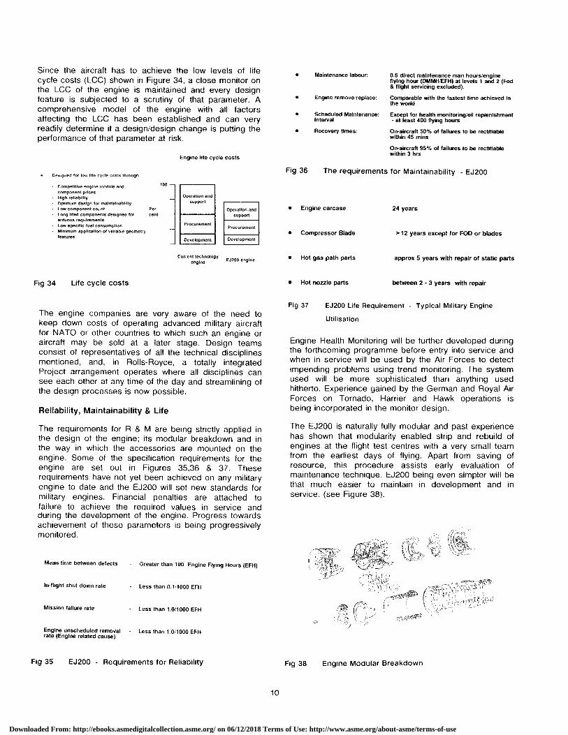
Since the aircraft has to achieve the low levels of lifecycle costs (LCC) shown in Figure 34, a close monitor onthe LCC of the engine is maintained and every designfeature is subjected to a scrutiny of that parameter. Acomprehensive model of the engine with all factorsaffecting the LCC has been established and can veryreadily determine if a design/design change is putting theperformance of that parameter at risk.
Engine life cycle costs
• Designed for low life cycle costs through:
Competitive engine'module and 100
component prices- High reliability Operation and
- Optimum design for maintainability support
• Low component count Per Operation and• Long lifed components designed for cent support
arduous requirements- Low specific fuel consumption Procurement
Procurement- Minimum application of variable geometry
featuresDevelopment Development
Current technologyengine
EJ200 engine
Fig 34 Life cycle costs
The engine companies are very aware of the need tokeep down costs of operating advanced military aircraftfor NATO or other countries to which such an engine oraircraft may be sold at a later stage. Design teamsconsist of representatives of all the technical disciplinesmentioned, and, in Rolls-Royce, a totally integratedProject arrangement operates where all disciplines cansee each other at any time of the day and streamlining ofthe design processes is now possible.
Reliability, Maintainability & Life
The requirements for R & M are being strictly applied inthe design of the engine; its modular breakdown and inthe way in which the accessories are mounted on theengine. Some of the specification requirements for theengine are set out in Figures 35,36 & 37. Theserequirements have not yet been achieved on any militaryengine to date and the EJ200 will set new standards formilitary engines. Financial penalties are attached tofailure to achieve the required values in service andduring the development of the engine. Progress towardsachievement of these parameters is being progressivelymonitored.
Mean time between defects - Greater than 100 Engine Flying Hours (EFH)
• Maintenance labour: 0.5 direct maintenance man hours/engineflying hour (DMMH/EFH) at levels 1 and 2 (Fod& flight servicing excluded).
• Engine remove/replace: Comparable with the fastest time achieved inthe world
• Scheduled Maintenance: Except for health monitoring/oil replenishmentInterval - at least 400 flying hours
• Recovery times: On-aircraft 50% of failures to be rectifiablewithin 45 mins
On-aircraft 95% of failures to be rectifiablewithin 3 his
Fig 36 The requirements for Maintainability - EJ200
• Engine carcase 24 years
• Compressor Blade > 12 years except for FOD or blades
• Hot gas path parts approx 5 years with repair of static parts
• Hot nozzle parts between 2 - 3 years with repair
Fig 37 EJ200 Life Requirement - Typical Military Engine
Utilisation
Engine Health Monitoring will be further developed duringthe forthcoming programme before entry into service andwhen in service will be used by the Air Forces to detectimpending problems using trend monitoring. The systemused will be more sophisticated than anything usedhitherto. Experience gained by the German and Royal AirForces on Tornado, Harrier and Hawk operations isbeing incorporated in the monitor design.
The EJ200 is naturally fully modular and past experiencehas shown that modularity enabled strip and rebuild ofengines at the flight test centres with a very small teamfrom the earliest days of flying. Apart from saving ofresource, this procedure assists early evaluation ofmaintenance technique. EJ200 being even simpler will bethat much easier to maintain in development and inservice. (see Figure 38).
5lil 2a ^,,,
gym.
In-flight shut down rate - Less than 0.11000 EFH
Mission failure rate • Less than 1.0/1000 EFH
Engine unscheduled removal - Less than 1.0/1000 EFHrate (Engine related cause)
Fig 35 EJ200 - Requirements for Reliability Fig 38 Engine Modular Breakdown
10
Downloaded From: http://ebooks.asmedigitalcollection.asme.org/ on 06/12/2018 Terms of Use: http://www.asme.org/about-asme/terms-of-use

Part 6
EJ200 Future Potential
As stated in the beginning of the paper the EJ200 enginewas specified to have a growth potential of at least 15%in thrust. This was deemed necessary in order to be ableto cope with normal aircraft equipment and capabilityincreases during service.
The actual engine design has very deliberately beenaimed at significantly larger growth than 15% so that theengine will remain a front line leader for at least 25 yearsin service on EFA and other applications.
The engine configuration allows the necessary growth inthe following essential parameters:
(a) Fan pressure ratio
(b) Turbine Entry Temperature Increase
(c) Core flow increases
within the existing engine scantlings.
Active programmes are already running in the enginepartner companies which will ensure that the technologywill be available for application to growth versions whenrequired. Additionally there are programmes aimed atproviding improved metal and composite materials for thehot and cold parts of the engine including structure, discsand casings.
In addition to the EFA application the engine is suitablefor re-engining existing aircraft and future generations oflight fighter, strike and advanced trainer aircraft. A typicalapplication tree is shown in Figure 39. The engine canbe offered in reheated or dry configuration. The dryconfiguration is illustrated in Figure 40.
EFA Growthengine version
Re-engineexisting fighter
EFA Twin Dry version forreheated strike/trainerfighter
\^\\ Reheated versionfor simple single
engine fighter
Derivativeengines with
advanced cores
Fig 39 EJ200 Marketing Application Tree
Fig 40 Dry Engine Details
Conclusion
This paper shows the excellent start made by the EJ200engine in the first year of the development programmefollowing contract signature. It illustrates confidence inthe ability of the engine companies to meet the designtargets within the programme timescales.
It also demonstrates the ability of the partner companiesto work together to prepare the technology data baseprior to project launch and to successfully meet theprogramme requirements.
11
Downloaded From: http://ebooks.asmedigitalcollection.asme.org/ on 06/12/2018 Terms of Use: http://www.asme.org/about-asme/terms-of-use


![CIE LANUS] :.](https://static.fdocuments.us/doc/165x107/6279bec09855d138f8553347/cie-lanus-.jpg)


![Acrich MJT 5050 Series - seoulsemicon.comSpecification]SAW0L60A_R3.0_1712.pdf · 0.3373 0.3534 0.3293 0.3384 0.3369 0.3451 C0 C1 C2 CIE x CIE y CIE x CIE y CIE x CIE y 0.3376 0.3616](https://static.fdocuments.us/doc/165x107/5bf955f609d3f2ab7d8cc0ef/acrich-mjt-5050-series-specificationsaw0l60ar301712pdf-03373-03534.jpg)
