EE 477 Final Report - College of Engineering - Purdue … · Web viewThis SPI will use 16-bit words...
171
ECE 477 Final Report Spring 2009 Team 4 das Autotünr Team Members: #1: Joe Blubaugh Signature: ____________________ Date: _________ #2: Diana Mui Signature: ____________________ Date: _________ #3: David Sutherland Signature: ____________________ Date: _________ #4: Matthew Swallow Signature: ____________________ Date: _________
Transcript of EE 477 Final Report - College of Engineering - Purdue … · Web viewThis SPI will use 16-bit words...

ECE 477 Final Report Spring 2009Team 4 das Autotünr
Team Members:
#1: Joe Blubaugh Signature: ____________________ Date: _________
#2: Diana Mui Signature: ____________________ Date: _________
#3: David Sutherland Signature: ____________________ Date: _________
#4: Matthew Swallow Signature: ____________________ Date: _________
CRITERION SCORE MPY PTSTechnical content 0 1 2 3 4 5 6 7 8 9 10 3Design documentation 0 1 2 3 4 5 6 7 8 9 10 3Technical writing style 0 1 2 3 4 5 6 7 8 9 10 2Contributions 0 1 2 3 4 5 6 7 8 9 10 1Editing 0 1 2 3 4 5 6 7 8 9 10 1Comments: TOTAL

ECE 477 Final Report Spring 2009
TABLE OF CONTENTS
Abstract 1
1.0 Project Overview and Block Diagram 1
2.0 Team Success Criteria and Fulfillment 3
3.0 Constraint Analysis and Component Selection 4
4.0 Patent Liability Analysis 10
5.0 Reliability and Safety Analysis 13
6.0 Ethical and Environmental Impact Analysis 16
7.0 Packaging Design Considerations 20
8.0 Schematic Design Considerations 23
9.0 PCB Layout Design Considerations 27
10.0 Software Design Considerations 30
11.0 Version 2 Changes 36
12.0 Summary and Conclusions 36
13.0 References 37
Appendix A: Individual Contributions A-1
Appendix B: Packaging B-1
Appendix C: Schematic C-1
Appendix D: PCB Layout Top and Bottom Copper D-1
Appendix E: Parts List Spreadsheet E-1
Appendix F: Software Listing F-1
Appendix G: FMECA Worksheet G-1
-ii-

ECE 477 Final Report Spring 2009
Abstractdas Autotünr is an automatic guitar tuning and music transcription system that will bring ease
to musicians by providing a quick and easy way to tune their instrument. It has preset and
user-customizable tunings in order to quickly retune the guitar for different songs. The music
transcription system will allow users to store anything they play to a USB mass storage
device as a MIDI file.
1.0 Project Overview and Block Diagram1.1 Design/Functionality Overview
das Autotünr has two modes of operation: tuning mode and transcription mode.
Figure 1-1. Motor Assembly and User Console
-1-

ECE 477 Final Report Spring 2009
Tuning mode allows the user to automatically tune their guitar to a default or stored
tunings by simply strumming the guitar strings. This is accomplished by attaching a
motor assembly to the headstock of the guitar. The motor assembly consists of six servo
motors and a bracket to hold to motors to the guitar. The servos can be arranged in many
ways to accommodate the different peg configurations of guitar headstocks. The servos
are also fitted with a peg holder which attaches to the guitar pegs for tuning. Sound data
can come from either the on-box microphone or by plugging in a stereo phono jack from
the guitar. This allows the user to tune both electric and acoustic guitars. While tuning,
the string being tuned, as well as frequency and tuning status, is displayed on the user
interface. The user is also able to program and store their custom tunings to the user
console for future use.
Transcription mode gives the user an easy way of recording the songs they play for
future use. The sound data from the guitar is recorded as a MIDI file and is saved to a
USB mass storage device. The mass storage device must be of the FAT32 format in
order for the file to be stored. About 6KB of sound data can be recorded which is around
a seven minute song. The MIDI file can then be imported into songwriting software such
as Finale for additional editing.
1.2 Block Diagram
das Autotünr takes audio data input from either a microphone or stereo phono jack. It
amplifies the audio input and feeds the amplified audio signal to the dsPIC where peak
detection frequency analysis is performed. Frequency data is then sent to the PIC24
microcontroller which sends the appropriate control signals to the motors for tuning. The
PIC24 also communicates with the USB host controller and outputs to the LED drivers
and LCD.
-2-

ECE 477 Final Report Spring 2009
Figure 1-2. Block Diagram
2.0 Team Success Criteria and Fulfillment2.1 Project-Specific Success Criteria
1. An ability to concurrently control six motors.
2. An ability to analyze the frequencies in a sound signal and compare them to desired
frequencies.
3. An ability to write music description files (MIDI) to a mass storage device.
4. An ability to display operating information including tuning status on a user
interface.
5. An ability to store user-input tuning preferences to onboard nonvolatile storage.
-3-

ECE 477 Final Report Spring 2009
2.2 Results
1. Successfully completed. All six motors are able to be controlled concurrently via
PWM signals from the microcontroller. Motors can also be driven individually.
Individual motor direction (clockwise/counter-clockwise) and speed could be
adjusted independently of the other motors.
2. Successfully completed. Frequencies in a sound signal are identified using peak
detection. The frequencies are then compared to a table of frequency values for note
identification (used for transcription). It is also used to identify which string needs to
be tuned in tuning mode.
3. Successfully completed. MIDI format data generated from note and duration data
gathered from the dsPIC. The data is sent over SPI to the USB host controller and
written as a MIDI file.
4. Successfully completed. The LCD displays the user menu and writes out status
messages in transcription mode. In tuning mode, it displays the current string
frequency, the target string frequency, and the direction the motor is turning.
5. Successfully completed. Five user-customizable tunings are built into das Autotünr.
The user can program the note value for each string and save the tuning to Flash
memory on the microcontroller.
3.0 Constraint Analysis and Component SelectionBecause of its musical nature, das Autotünr has real-time responsiveness in transcription
mode and a fast response in tuning mode as well. The tasks of tuning and transcription are
fundamentally sound analysis problems; therefore, the device has enough power to perform
signal processing techniques quickly and at a high resolution. The device also interfaces to
consumer USB storage products and requires enough power to drive six small motors.
3.1 Design Constraint Analysis
There are a number of design constraints acting on the project that were considered. The
computational requirements of signal processing algorithms necessitated a powerful
digital signal processor (DSP). General purpose input/output (GPIO) were used to power
-4-

ECE 477 Final Report Spring 2009
a user interface. Numerous on-chip peripherals, including analog to digital converters
(ADCs) and pulse-width modulators (PWMs) were also required. An external USB
controller was also needed to connect to storage devices. The power requirements
created by driving motors was addressed, as was the packaging constraints derived from
the need to connect the device to a guitar. Finally, cost constraints were also considered
by comparing das Autotünr to other tuning devices that were both simpler and more
complicated than it.
3.2 Computation Requirements
In order to tune a guitar, the product needed to be able to sample analog audio and
determine frequency characteristics of the sound very accurately. When it comes to
musical notes, the human ear can distinguish between frequencies as fine as 2 Hz apart
[1]. In addition, small imperfections in tuning can lead to an interference phenomenon
called 'beating.' For these reasons, it is essential to have a fine frequency resolution in
tuning mode. This requires a large number of samples: in the Discrete Fourier Transform
(DFT), the frequency resolution of samples is the sampling frequency divided by the
number of samples computed [2]. While zero-padding can be used to reduce the number
of samples that actually need to be taken, memory space for these zeros must still be
reserved in order for most available DFT libraries to compute correctly. In order to
obtain good tuning performance, a frequency resolution of 1 Hz or less should be used,
and a sampling rate of at least 2*440Hz or 880 Hz should be used. Consequently
memory space for at least 1024 samples should be available.
In transcription mode, absolute accuracy becomes less important, as long as notes in a
musical scale can be distinguished. Real-time performance, on the other hand, becomes
imperative so that accurate timing information can be captured. Taking these two
requirements together, it becomes apparent that both a large amount of data memory (for
fine-resolution spectrum analysis) and a fast processor core (for real-time performance)
are necessary to successfully execute the functions of the device. For this reason, it is
useful to separate the DSP functions from the 'device management' functions.
-5-

ECE 477 Final Report Spring 2009
3.3 Interface Requirements
The device will interface with a character-mode LCD to provide feedback to the user
and will accept pushbutton inputs to allow the user to control device function.
Interfacing to the LCD will require one GPIO pin and a software routine to control the
issuing of commands. It may also be possible to use a built-in serial communication
peripheral to handle this. At least four pushbuttons will be needed to allow the user to
navigate a nested menu structure, so at least four GPIO pins will be needed to handle
inputs from these. Because these are simply switches, a high-value resistor will be used
to keep sink current on these pins to a negligible value. In addition, three GPIO pins will
be used to control an RGB LED. These will essentially be software PWMs utilizing one
of our microcontroller's on-board timers. Most RGB LEDs require 2.5Vf to operate
correctly, so the remaining voltage will be dissipated by a resistive element on each line.
Since each line will be driving only one LED, amplification circuitry will not be
necessary.
3.4 On-Chip Peripheral Requirements
In order to sample audio one channel of ADC is required. In order to have fine-grained
amplitude numbers, a 10-bit or greater ADC is desired. To simultaneously drive the
servo motors that will tune the strings, six channels of PWM output are necessary. A
pair of matching serial interfaces will be needed on the DSP and microcontroller in order
to create a communication channel. In addition, two more serial interfaces will be
needed to interface with the USB host controller and the user interface LCD. Several on-
chip timers will be needed on both the DSP and the microcontroller in order to maintain
real-time communications and accurately control motors.
3.5 Off-Chip Peripheral Requirements
There was one required off-chip peripheral: a USB host controller to manage loading
MIDI files to an external USB storage device. The controller will communicate with the
microcontroller through a serial communication interface.
-6-

ECE 477 Final Report Spring 2009
3.6 Power Constraints
Because the device includes motors which consume much more power than the electronic
components, the project is A.C. powered without a battery backup. The motors required
for the project can run on unregulated DC voltage but have a maximum 6VDC source
voltage. The supply also needs to be able to provide several amperes of current in order
to drive the motors, supply power to the electronics, and supply the USB specified 500
mA of supply current. Next to this, the current draw of digital hardware is only a few
hundred milliamps. A supply should be able to provide at least 2.5 amps of current.
3.7 Packaging Constraints
The device includes a piece that can be attached to the headstock of an acoustic guitar, as
well as a second piece containing the user interface, microphone, and USB port. The
cabling connecting these pieces includes both power and control lines for the tuning
motors. The control lines need to be adequately shielded to prevent cross-talk. The
project is packaged as a single unit that the guitar is laid on or a multi-piece unit
connected by cables.
3.8 Cost Constraints
das Autotünr fills the void between two commercially available products: electronic
chromatic tuners like the Korg ABCDERF that can be found for $14.99 at jr.com and
integrated automatic tuning systems like the Gibson Robot guitar. These integrated
solutions are very expensive, adding about $800 in the Gibson guitars. das Autotünr is
intended to work with any guitar without modification and should cost less than $400 in
order to make it a compelling tool for guitar enthusiasts and technicians.
3.9 Component Selection Rationale
There are four major electronic components in this design. A microcontroller directs the
motors, sends data to a USB controller, and controls the user interface. A DSP samples
analog audio, performs a spectral analysis and communicates tuning and note information
to the microcontroller through a serial interface. A USB controller takes MIDI data sent
to it by the microcontroller and writes it to a USB storage device. An audio amplifier is
-7-

ECE 477 Final Report Spring 2009
needed to bring the low level signals from a microphone or phono cable to a higher-
voltage signal that is better for AD conversion.
3.9.1 Microcontroller
Since the microcontroller is responsible for simultaneously controlling six
separate motors, the number of PWM outputs is very important. Timer channels
were also at a premium. Serial devices for interprocessor communication were
another key feature guiding microprocessor selection. Two microcontrollers that
fit within the essential design constraints are Microchip's PIC24HJ128GP306 and
Freescale's MC9S12DT256. Each microcontroller has eight PWM channels, at
least eight timers, and at least two serial communication channels. Each also has a
number of peripherals we will not be using: ADCs and CAN interfaces are
available on both processors [3],[4].
In most categories, the PIC processor is superior. It is available with 16 kilobytes
(KB) of data memory as opposed to the MC9S12's 12 KB. It has 64 pins
compared to the MC9S12's 112 [3],[4], making it easier to solder to the board.
The PIC's unit price of $5 is very favorable compared to the MC9S12's price of
$13 [5],[6]. Microprocessor and DSP selection also influenced each other. PIC
offers DSP chips that have a very similar programming model to their
microprocessors. This shared environment helps speed software development, so
the PIC24 was selected for this design.
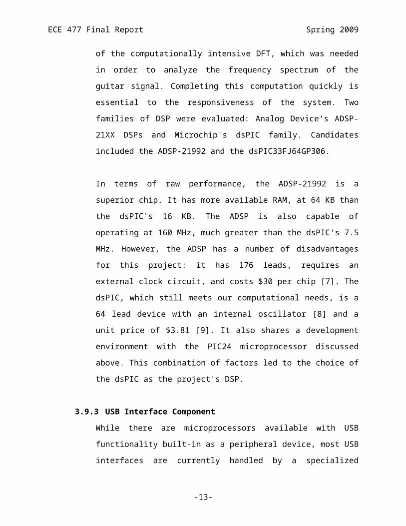
3.9.2 Digital Signal Processor
The decision to include a separate DSP was made because of the computationally
intensive DFT, which was needed in order to analyze the frequency spectrum of
the guitar signal. Completing this computation quickly is essential to the
responsiveness of the system. Two families of DSP were evaluated: Analog
Device's ADSP-21XX DSPs and Microchip's dsPIC family. Candidates included
the ADSP-21992 and the dsPIC33FJ64GP306.
-8-

ECE 477 Final Report Spring 2009
In terms of raw performance, the ADSP-21992 is a superior chip. It has more
available RAM, at 64 KB than the dsPIC's 16 KB. The ADSP is also capable of
operating at 160 MHz, much greater than the dsPIC's 7.5 MHz. However, the
ADSP has a number of disadvantages for this project: it has 176 leads, requires an
external clock circuit, and costs $30 per chip [7]. The dsPIC, which still meets our
computational needs, is a 64 lead device with an internal oscillator [8] and a unit
price of $3.81 [9]. It also shares a development environment with the PIC24
microprocessor discussed above. This combination of factors led to the choice of
the dsPIC as the project's DSP.
3.9.3 USB Interface Component
While there are microprocessors available with USB functionality built-in as a
peripheral device, most USB interfaces are currently handled by a specialized
microprocessor or other device. Two different solutions were considered for this
component: FTDI's Vinculum USB Host Controller VDIP1 and the Cypress
Technology SL811HS. The SL811HS operates at 3.3V, the same supply voltage
as our other major components [10], while the VDIP1 requires a 5V input [11].
Both take 3.3V logic inputs, so no translation is required. The most compelling
difference between the two is that the VDIP1 has free firmware available that
implements a FAT file system interface while the SL811HS does not. Because
this reduces the software workload, the VDIP1 was selected.
3.9.4 Audio Amplifier
Signals from microphones and electric guitar cables are very low voltage, so an
amplifier is needed in order to bring the device to a level that is compatible with
our DSP's ADC. An audio amplifier is required because their circuitry is designed
to have a flat frequency response in the audible frequencies of 20 Hz – 30 KHz
and they produce very clean signals. Two candidate devices are the LM386
(available from National Semiconductor, Contek, and FCI) and the NJW1105
from New Japan Radio Company. Both are designed to operate on supply
voltages of 4 to 12 volts and do not require bipolar power supplies [12], [13]. The
-9-

ECE 477 Final Report Spring 2009
NJW1105's primary advantage is its unification of two amplifiers in one package.
It also costs more than twice as much as an LM386 and does not provide an
externally settable gain. Because of these facts, the LM386 is more suitable, even
though two of them will need to be populated and routed.
4.0 Patent Liability Analysis
There are several aspects of the device which could be at risk for patent liability. One of the
main features involves tuning the six strings of a guitar concurrently. Another main function
involves performing a frequency analysis on the incoming sound signal from the guitar to
identify notes. Information such as tuning status is displayed through a user interface. Lastly,
the device can be in transcription mode when not tuning so that it records incoming sound
data in the MIDI file format and stores the file on a USB mass storage device.
4.1 Results of Patent and Product Search
4.1.1 Automatic string instrument tuner (Patent No. 5,767,429) [14]
Filing date: November 9, 1995
Abridged Abstract: This is a tuning system for automatically tuning a stringed
musical instrument (such as guitars, harps, pianos, etc.) The tuning system tunes
the string of a musical instrument to a user-selected predetermined frequency.
Key Claims: 1 – The tuning apparatus removes predetermined signal harmonics
from the signal and converts the signal from analog to digital for processing.
2 – The signal processing is done in a central processing unit with RAM & ROM.
3 – There are musical pickup sensors which include at least one microphone.
4 – There is a plurality of motors which are driven by an electrical control signal.
The electrical control signal is a function of the difference between the incoming
signal and its reference value.
4.1.2 System and method for automatically detecting a set of fundamental frequencies
simultaneously present in an audio signal (Patent No. 6,140,568) [15]
Filing Date: November 5, 1998
Abridged Abstract: This is a method for detecting and identifying several
frequencies simultaneously present in an audio signal. It also identifies the
-10-

ECE 477 Final Report Spring 2009
duration, amplitude, and phase of the frequencies and filters out the harmonic
components to determine the fundamental frequency. This system also creates a
computer-readable instruction code that decomposes the signal into its component
sine waves.
Key Claims: 1 – This system identifies one or more fundamental frequencies
simultaneously present in a complex signal by decomposing the signal into sine
wave components and filtering our harmonic frequencies.
2 – Decomposing is carried out by obtaining correlation scores by comparing the
complex signal to the reference frequencies. One of the steps in obtaining the
correlation score involves subtracting the reference frequencies from the complex
signal.
3 – The reference frequencies are stored and utilized as a sine wave table.
4 – The system filters our harmonic frequencies by subtracting a portion of the
amplitude for multiples of the fundamental frequencies.
5 – The detected frequencies as well as their respective durations and amplitudes
are recorded as MIDI data.
4.1.3 Tuning apparatus for stringed instruments (Patent No. 4,889,029) [16]
Filing Date: September 2, 1988
Abridged Abstract: This is a guitar tuner with a slot-shaped opening in the head
used for grasping the key of an instrument such as a guitar. The head is driven by
a motor which rotates about an axis. An input sensor detects the tone of the string
of the instrument and converts it to a square wave of the detected frequency. A
microprocessor compares this frequency with the closest adjacent defined
frequency for the instrument and drives the motor accordingly. A digital user
interface is provided to show tuning information and to allow user overrides while
tuning.
Key Claims: 1 – There is a sensor that detects the note produced by a string when
it is plucked and calculates the fundamental frequency of the note by comparing
against a table of predetermined required frequencies. The motor associated with
the string then rotates the peg clockwise or counterclockwise in response.
2 – There is a visual indicator that indicates whether the string is tuned to the
-11-

ECE 477 Final Report Spring 2009
predetermined frequency.
3 – The sensor generates from the tone of the string a rectangular wave in which
the comparator uses to compare against the required frequencies.
4 – There is a manual override so that the user can choose to tune the string to
another one of the stored frequencies.
4.2 Analysis of Patent Liability
4.2.1 Automatic string instrument tuner .
There are many different parts of the claim in which literal infringement could be
claimed. Our device uses a microphone as a pickup device and converts the
analog sound to a digital signal for processing. All of the computation is
performed on a central processing unit which has RAM and ROM, and electrical
control signals are sent out to motors for tuning. However, these functions can be
considered “obvious” since they are present in most devices, not uniquely
instrument tuners. The main difference between our device and this patent is that
we do not remove the harmonics from the sound signal during the signal
processing. Instead, we analyze the whole frequency spectrum of the signal and
identify the peaks of the signal as the fundamental frequency. This difference in
how the frequency analysis is performed shows that the same function is not
performed in substantially the same way.
4.2.2 System and method for automatically detecting a set of fundamental frequencies
simultaneously present in an audio signal.
The MIDI transcription mode of our device most infringes upon this patent. An
area in which literal infringement may occur is that we both analyze a complex
signal, meaning that the signal contains one or more notes and store the sound
data (i.e. frequency, duration, and amplitude) in a MIDI file. However, the actual
process in how the devices process the sound information for storage is very
different. Our device performs a discrete Fourier transform (DFT) on the sound
signal and uses peak detection to filter out the fundamental frequencies. This is
very similar to the patented system which decomposes the sound signal into sine
waves and filters out the harmonics by subtracting them from the sine waves. The
-12-

ECE 477 Final Report Spring 2009
frequency analysis is performed in substantially the same way.
4.2.3 Tuning apparatus for stringed instruments .
das Autotünr is extremely similar to this tuning apparatus in many aspects, which
could form a basis for literal infringement. Our device has a user console which
indicates tuning status to the user. It has a user-override mode where you can
make custom tunings for your guitar. It also compares the note from the sensor
input to a value of reference frequencies stored in a table and uses that data to
form a motor control signal for the associated peg. As with the previous patent,
there is a substantial similarity in how the frequency analysis is performed in this
apparatus. In the apparatus, the sensor generates a square wave from the input
tone of the string and feeds the square wave into a comparator to compare against
the reference frequencies. This is a different approach to our DFT/peak detection
method, but because both are methods of frequency analysis, there is an issue
under the doctrine of equivalence. Therefore, it could be said that both devices are
substantially similar.
4.3 Action Recommended
The analysis between das Autotünr and the three patents in question show that the
devices are not substantially different. There are definite similarities between das
Autotünr and all of the other devices and systems, and in many cases, literal
infringement could be inferred. There may be other patents in which our device would
infringe upon since our method of frequency analysis is used in other applications, so if
we were going to commercially distribute this product, we would need future research.
In the case of patent infringement, which is very likely for our device, we would try to
acquire a license in order to manufacture our product.
5.0 Reliability and Safety Analysis The main safety issue that concerns possible user injuries is the possibility of breaking strings
under tension. Broken strings can swing at high speeds and could cause injury if they strike a
person in the eye for example. Other safety issues concern only the health of components in
das Autotünr itself.
-13-
ECE 477 Final Report Spring 2009
5.1 Reliability Analysis
The components in das Autotünr most likely to fail are the PIC24, dsPIC33, 5V voltage
regulator, and the 3.3V voltage regulators. The PIC23 and dsPIC33 were selected as
likely to fail because of their complexity and large number of pins [3],[8]. The voltage
regulators were selected because they are the hottest running components on the board
[18],[19]. Below are tables for each of these devices explaining the calculations and
assumptions in order to find the number of failures per million hours [17].
PIC24 λp = (C1 * πT + C2 * πE) * πQ * πL
Parameter name
Description Value Comments
C1 Die Complexity 0.28 16 Bit microcontroller
πT Temperature Factor 0.35
TC = 50C, θJC = 10,
P = .29W
TJ = TC + θJC*P = 52.9
C2 Package Failure Rate 0.032 Nonhermetic SMT
πE Environment Factor 4.0Similar to handheld communications
equipment (Ground Mobile)
πQ Quality Factors 10.0 Commercial product
πL Learning Factor 1.0 In production for > 2 years
Entire design: λp = 2.26 MTTF ≈ 50 years
Table 5-1. PIC24 MTTF Analysis
dsPIC33 λp = (C1 * πT + C2 * πE) * πQ * πL
Parameter name
Description Value Comments
C1 Die Complexity 0.28 16 Bit microcontroller
πT Temperature Factor 0.35
TC = 50C, θJC = 10,
P = .29W
TJ = TC + θJC*P = 52.9
C2 Package Failure Rate 0.032 Nonhermetic SMT
πE Environment Factor 4.0Similar to handheld communications
equipment (Ground Mobile)
πQ Quality Factors 10.0 Commercial product
πL Learning Factor 1.0 In production for > 2 years
Entire design: λp = 2.26 MTTF ≈ 50 years
-14-

ECE 477 Final Report Spring 2009
Table 5-2. dsPIC33 MTTF Analysis
L4941 λp = (C1 * πT + C2 * πE) * πQ * πL
Parameter name
Description Value Comments
C1 Die Complexity .01 1 to 100 transistors
πT Temperature Factor 2.8
TC = 50C, θJC = 10,
P = 1.975W
TJ = TC + θJC*P = 69.8
C2 Package Failure Rate .0012 Nonhermetic DIP
πE Environment Factor 4.0Similar to handheld communications
equipment (Ground Mobile)
πQ Quality Factors 10.0 Commercial product
πL Learning Factor 1.0 In production for > 2 years
Entire design: λp = .328 MTTF ≈ 300 years
Table 5-3. L4941 Linear Regulator MTTF Analysis
AP1117 λp = (C1 * πT + C2 * πE) * πQ * πL
Parameter name
Description Value Comments
C1 Die Complexity .01 1 to 100 transistors
πT Temperature Factor 1.4
TC = 50C, θJC = 10,
P = 1.975W
TJ = TC + θJC*P = 58.2
C2 Package Failure Rate .0012 Nonhermetic DIP
πE Environment Factor 4.0Similar to handheld communications
equipment (Ground Mobile)
πQ Quality Factors 10.0 Commercial product
πL Learning Factor 1.0 In production for > 2 years
Entire design: λp = .188 MTTF ≈ 600 years
Table 5-4. AP1117 Linear Regulator MTTF Analysis
Based on the calculations above there is little to no concern for our “hot” parts. Both of
the linear voltage regulators have failure rates well below one failure per million hours,
the standard “acceptable” failure rate. At first glance, it would appear that the
microcontrollers do not meet acceptable failure rates. However, the calculations above
-15-

ECE 477 Final Report Spring 2009
include a quality factor of 10 due to the fact that the controllers were acquired
commercially. Both controllers would have acceptable failure rates with quality factors
of 4 or less. This is still a conservative quality factor and should not yield an inaccurate
result. Based on these conclusions it appears that the current design itself needs no
further refining with respect to reliability.
5.2 Failure Mode, Effects, and Criticality Analysis (FMECA)
das Autotünr can be divided into five connected subsystems: power, audio,
microcontroller, user Interface, and motor. Failures that are considered to be of a high
criticality rate involve the risk of user injury. The four failures listed in the FMECA
chart below that warrant high criticality are overvoltages that could cause components to
overheat and lead to fires and the loss of motor control to the point that strings are
broken. Because user safety is of utmost concern, these failure modes would be required
to have a failure rate of no more that 1 in 109 hours. Failure modes that will only cause
harm to individual components or cause inconveniences to the user are labeled as having
low criticality. Although these failures are unlikely to cause harm to the end user, das
Autotünr is expected to perform well for years to come so a failure rate of no more than
1 in 106 hours is acceptable.
6.0 Ethical and Environmental Impact Analysis
As is with any commercial product, ethical and environmental concerns are paramount to its
inception. Since our product is utilized by interfacing with the user’s own unique guitar, special
care is taken when testing the possible ways individual guitars can vary to ensure correct,
reliable and safe operation. In addition, many failsafes have been built into the design with the
intent to lessen the probability of device failure. With regards to environmental impact, thought
was put into how to minimize the inclusion of toxic substances in the design. The user also
should be informed of how to properly dispose of the device at the end of its lifetime.
6.1 Ethical Impact Analysis
When considering the ethical impact of das Autotünr, it is important to first look at how
the device will be used. The device will be attached to the headstock of a user’s guitar
-16-

ECE 477 Final Report Spring 2009
with one motor firmly attached to each tuning peg, totaling six motors. In order to
ensure the tuning assembly does not slip off the guitar, it will be secured by tightening
wing nuts on the underside of the motor brackets. Since removing the motors in case of
a failure is not feasible, there must be a failsafe to ensure that harm does not come to the
guitar or the user if the device becomes unresponsive and the motors are stuck rotating .
If the failsafe is not engaged, and if all other designed safety mechanisms have failed,
the most likely scenarios would involve breaking a guitar string, resulting in injury to
the user or causing permanent damage to the guitar itself. Since user safety is
paramount, the safety mechanisms and failsafes must be designed in such a way that the
probability this situation occurs is negligible.
The design includes many different routines to ensure the correct, safe and reliable
operation of the tuner. During normal operation, das Autotünr should tune all six strings
concurrently, but in the case of any discrepancy in the frequency detection or perceived
motor operation, the device will enter what is called “single string” tuning mode. The
screen will instruct the user to play one string at a time, starting with the lowest string.
This way, the device can more reliably detect the frequency of the string and motor
control can further be verified. If the frequency of the string does not change when the
motor is set to rotate, the device will exit tuning mode and the user will be prompted to
check the motor connections. In addition, if any of the string frequencies indicate the
guitar is being tuned beyond safe string tension levels, the tuning routine will exit. Also,
at any time during the tuning process, if the user feels that the device is operating
unsafely or that they want to halt the tuning process, they can press a button on the
control box which will stop all motor operation. Given all of these safety mechanisms,
the design of das Autotünr is certainly conscious of failures, but extensive testing must
follow to make certain the device’s proper functioning under a variety of conditions.
To this end, it is important to analyze and test the set of variables involved its intended
operation. If das Autotünr were to go into production, it might be assumed that it would
tune any guitar, but further testing would need to be performed to verify the breadth of
its capabilities. This testing would involve confirming the tuning capabilities of the
-17-

ECE 477 Final Report Spring 2009
device when used with different guitar types (acoustic and electric), string materials,
string gauges and pickups (in the case of an electric guitar). If it was found that
performance was sub-par or that it would be dangerous to use das Autotünr given any
combination of these variables, further investigation of the failure would be needed. If
the device design could be easily, quickly and unobtrusively modified, it would be a
reasonable course of action to go forward with simple changes to increase the likelihood
of operational success. If the changes would be too drastic, difficult or impossible given
the present design, this incompatibility would have to be printed on the packaging, to
prevent the purchase of a product for which the consumer would have no use. During
the course of testing, if it was shown that the number of cases where das Autotünr failed
to perform its function was unacceptably high, or if any test case resulted in high
likelihood of injury to the user, the design would require significant modifications
before it would be ready for commercial sale.
When the device passed all testing of its intended functionality, documentation must
clearly provide directions for safe operation of das Autotünr. Additionally, it should be
documented which instruments das Autotünr is not intended to be used to tune. This
device was intended to be an electric or acoustic guitar tuner and its performance will
not be validated on other similar string instruments. There should also be a warning in
the manual stating that there is a risk of string breakage resulting in personal injury and
which steps should be taken to lessen these risks. It should also be mentioned that das
Autotünr is not a toy and that it is not intended to be used by children.
Additionally, the user should be warned against opening the box, due to the possibility
of device alteration. If something were to become unplugged from the board, or if some
metallic object were to be set loose within the control box, there would be a possibility
that the device would not work or that two traces could short, causing a fire. To prevent
this possibility, there should be a warning sticker placed across the box seam stating this
box should not be opened. Also, this warning should be echoed in the user manual,
further listing the possible complications. For the same reasons stated above, if das
Autotünr were to be mass produced, the motor breakout circuit attached to the motor
-18-

ECE 477 Final Report Spring 2009
assembly should be encased in plastic to ensure no accidental shorting of traces.
6.2 Environmental Impact Analysis
In order to present an ethically-sound product, the environmental impact of the device’s
manufacture and disposal must be thoroughly considered. The foundation of an
environmentally-friendly product begins with how it is manufactured and which parts go
into its production. One of the greatest health hazards present in most electronic devices
is lead, and if ingested in sufficient quantities, can cause neurological damage, hearing
loss or even cancer [20]. It is commonly found in solder and is frequently used to create
the traces on a printed circuit board. Fortunately, there are alternatives which eliminate
the use for leaded products. Lead-free solder is frequently used by manufacturers
looking to eliminate their environmental impact. For this reason, it is seen as positive,
but it has not been adopted as an industry-standard due to its relatively-inferior
performance. This shortcoming is especially evident with regard to solder joint
reliability, a common failure mode for electronic devices [21]. Furthermore, both lead-
free solder and lead-free PCBs come at a price premium as compared to their leaded
counterparts [22]. In addition to manufacturing the PCB using lead-free processes,
RoHS approved ICs can be employed. Devices carrying this label must have less than
0.1% by weight of lead, mercury, chromium, PPBs and PBDEs and less than .01% by
weight of cadmium [23]. Another upside to using these parts is that they are frequently
priced the same as non-RoHS parts. This means that there will be minimal impact to the
bottom line, but a net decrease in toxic substances contained in the device.
During normal use of das Autotünr, any direct environmental impacts would be small.
One possibility might be that if the LCD on the control box were to be broken, the
mercury in the fluorescent backlight could spill out. Another impact might be that the
device, when left plugged in, will continue to draw electricity due to the losses in the
AC/DC power supply and idle current draw of the circuitry. The user manual should
recommend that the unit is unplugged when not in use to reduce unnecessary power
consumption.
-19-

ECE 477 Final Report Spring 2009
In contrast to the relatively slight impacts of usage, the environmental impact at the end
of das Autotünr’s lifetime has the potential to be significant. Proper disposal of the
device is key in minimizing both its landfill footprint and its potential to release toxic
substances to the environment. Both the Lexan brackets used for the motor mounting
and the plastic control box are able to be recycled at most community recycling centers.
Both the motors and the PCB can be recycled either at electronics-accepting local
recycling centers or at specialized electronic recycling centers [24]. Unfortunately, the
availability will vary by location, but the user manual should list a URL to the EPA site
which provides a search for recycling centers by city. This should increase the
likelihood that the end-user will actually recycle the device, rather than putting it in the
trashcan.
7.0 Packaging Design Considerations
das Autotünr has two packaging pieces connected by a cable. The main package is a
box that is 6.3” x 6.3” x 3.5”. The top of the box contains an LCD screen and four push
buttons to facilitate user interfacing, two RGB LEDs, and a cutout for a microphone.
The sides of the box have access points for DC power from a wall wart, a USB
receptacle for a flash drive, power and communication to the six servo motors, and a ¼”
stereo phone jack for input from an electric guitar. The secondary package is a set of
plastic ‘L’ shaped brackets that is held together with wing nuts to form a ‘U’ shape to
hold the guitar’s headstock. Along the vertical section of each plastic piece is a cutout
that the six servos (three on each side) will slide into. Two vertical pieces of plastic
connect to the “L” shaped brackets to hold the servos in place.
7.1 Commercial Product Packaging
There are two commercial products that currently on the market that are similar to das
Autotünr. The first product, String Master, is less sophisticated and less expensive than
das Autotünr. The second product, Robot Guitar, is much more sophisticated and more
expensive than das Autotünr. There is an open area between these two products that das
Autotünr will be able to fill with a packaging concept that merges the two extremes
-20-

ECE 477 Final Report Spring 2009
existing on the market.
7.1.1 String Master by Action Tuners
String Master is a hand-held battery operated device that will tune one guitar
string at a time. With the microphone attachment to allow for tuning of acoustic
guitars, the String Master costs approximately $125. String Master’s packaging is
very small and has little user interface. das Autotünr will have slightly larger
packaging, but will have a user interface to change to different tunings (String
Master only does standard) as well transcribe music.
To tune a guitar with String Master the user would select the string to be tuned
with a button, place the peg-holder on the string’s tuning peg, and strum that
specific string. A motor in the String Master will turn the peg while the user must
hold the assembly still and continue strumming. This process will then be
repeated for the 5 remaining strings. The only similarity to das Autotünr’s
packaging here is the motor and peg holder. das Autotünr has a similarly shaped
peg-holder attached to a motor, but it will have six sets of them. A major
difference is that the user of a String Master will have to hold their guitar, hold
the String Master steady, and strum a string all at the same time. The same user
only has to strum their guitar with das Autotünr.
7.1.2 Robot Guitar by Gibson
Robot Guitar is not equipment used to tune a guitar, but actually a guitar that has
motors installed in its tuning pegs and circuitry associated with controls in its
body. This is a high-end design and will cost over $1,000 more than an electric
guitar of the same type without the robot technology. The packaging for this
guitar is sleek and one would not know there was anything different about a robot
guitar simply by looking at it because everything that makes it different is housed
inside the guitar. das Autotünr’s packaging is on the other extreme in that all
equipment will be external to the guitar. The Robot Guitar tunes one peg at a
-21-
ECE 477 Final Report Spring 2009
time when instructed using a knob on the body of the guitar. There is no need for
the user to strum at all because the Robot Guitar uses the tension of the strings for
finding the proper tone. However, one major downside of the Robot Guitar is that
it only works on a single electric guitar. This gives das Autotünr an edge because
it can be used on multiple acoustic and electric guitars.
7.2 Project Packaging Specifications
das Autotünr consists of two separate parts connected by a cable. The first part is a
plastic box with dimensions 6.3” x 6.3” x 3.5” (Appendix B-7). The top of the box
holds two RGB LEDs, an LCD screen, four push-buttons for menu navigation, and a
microphone for acoustic guitar audio input. Along the sides of the box there are four
connections between the internal PCB and the outside world. There is a cut-out for a
user supplied USB storage device to be connected to an on-chip USB receiver, a cut-out
for a power and communication cable to drive the six servos, a jack for DC power input
from a wall-wart, and a jack for stereo audio input from an electric guitar.
The second piece of packaging for das Autotünr consists of four pieces of 3mm thick
Lexan. The first piece is an “L” shape 400mm long, 94.8mm tall, and 127mm wide
(Appendix B-1). The vertical section of the bracket has a cutout that allows the servo
body and tab (Appendix B-5) to slide through the middle of the plastic at one end, but
only the body through to the other side. The horizontal part of the piece has two long
and narrow slits that has wing nuts to connect the two brackets together. The second
piece is a rectangle 400mm long and 94.8mm tall (Appendix B-2). It has a cutout that
matches the vertical section of the first piece exactly. The third piece of plastic is like
the first except that it is only be 200mm long and 91.8m tall (Appendix B-4). Finally,
the fourth piece is a rectangle 200mm long and 91.8mm tall (Appendix B-3). It has a
cutout that matches the vertical section of the first piece exactly.
The packaging comes together with three servos between each bracket and backplate
and the shorter bracket on top of the longer one. The guitar to be tuned will have its
headstock laid into the created “U” shape and the servos adjusted to match the peg
-22-

ECE 477 Final Report Spring 2009
locations. The brackets can then be pushed together and secured with wing nuts
underneath the assembly.
7.3 PCB Footprint Layout
The major components selected for das Autotünr are a microcontroller, DSP chip, USB
controller, analog amplifier, and two voltage regulators as well as several headers for
connections outside of the PCB. The footprint choices for the microcontroller and DSP
chip were similar (QFP or QFN and 64 or 122 pins). The choice of 64 pin QFP
packaging was made for both chips. QFP was chosen over QFN because of the relative
ease of soldering a QFP package. The 64 pin models were chosen over the 122 pin ones
because there was no functional benefit added by increasing the number of pins that
would need to be soldered. We chose the through-hole package for our USB controller
instead of the QFP chip because it had a low pin count and through-hole solder joints are
not difficult to make. It also minimized the amount of pins to only the ones that would
be necessary for communication with all of the other extraneous connections made.
The outside dimensions of the PCB for das Autotünr is 5.872” x 4.352”. This board fits
into the proposed box and has enough surface area for our major components and
estimated trace. The larger dimensioned components included on the layout are the
USB controller (43mm x 18mm), microcontroller (10mm x 10mm), DSP chip (10mm x
10mm), and the audio amplifier (10mm x 6mm). The location of the components on the
PCB is such that signals can be segregated. High current traces mainly run in the upper
left hand corner. Analog signals are mostly be contained in the lower left hand corner,
and all digital signals remain on the right side of the board. Power connects to the board
near the upper center and runs along the division lines between the signals. The voltage
regulators are located on the left side of the board so they can be close to the power
source and drive out to their respective components.
8.0 Schematic Design Considerations
The design of the product thereby necessarily includes substantial current consumption in the
motors and analog circuitry for the audio inputs. In addition, there are a number of digital
-23-

ECE 477 Final Report Spring 2009
interfaces: an LCD, USB storage device, and DSP-microprocessor communication channel.
Because of the mixed-signal nature of the design, care was to be taken to couple the
subsections appropriately.
8.1 Theory of Operation
8.1.1 Analog Input, Amplification, and Output
Analog audio is input to the circuit through either an electret condenser
microphone or a 1/4” phone jack. These inputs are each mV-level signal and need
to be amplified before being sampled by the dsPIC. A stereo phone jack serves as
a mechanical switch that indicates when a plug is inserted. This switch provides
an enable signal that drives an SPDT IC, connecting either the microphone or the
jack through an RC low-pass filter to the input of an LM386 low-voltage audio
amplifier operating off of a 5VDC rail. 5VDC is used here because of its use in
other circuits and the LM386's incompatibility with a 3.3VDC supply [13]. The
amplifier's output is voltage divided to adjust its range from 0 – 5VDC to and
ADC-compatible 0 – 3.3VDC. This output is then coupled to the dsPIC's ADC
input 9.
8.1.2 Power System
There are three supply voltages present in this device. A rail of 6V unregulated
DC comes from a wall-wart power supply and provides direct power to the
device's servos. From the 6V rail, two regulated voltages are produced by LDO
linear regulators: 5VDC and 3.3VDC. Bulk capacitance on the 6V line provides
instantaneous current for motor startup draw, and similar capacitors are used on
the 5VDC and 3.3VDC lines in order to provide current for logic switching. If all
six motors stall at once, they can collectively pull 2.4 amperes. The 5VDC line
needs to supply up to 700 mA: 160 mA for the LCD screen, 520 mA to power the
USB bus and USB controller, and 20 mA for the audio amplifier circuit. The 3.3V
rail could be drawn up to a few hundred mA if all digital devices are drawing their
maximum safe current.
8.1.3 LED Output
Two bi-color common cathode red/green LEDs are used to provide feedback to
the user. Because the Microchip components in use can only source and sink a
-24-

ECE 477 Final Report Spring 2009
maximum of 4 milliamps (mA), a BJT circuit was designed to provide up to 20
mA of current to each of the four LED anodes. The transistor base input is a
GPIO output from the PIC24HJ128GP306. The circuit uses two dual BJT PNP
array ICs in 6 pin packages to save layout space on the board.
8.1.4 dsPIC
The dsPIC33FJ64GP306 runs on a supply voltage of 3.3VDC and uses its internal
oscillator set to its maximum instruction cycle frequency of 40 MHz [8]. This is
to ensure that the device's DSP processing completes as quickly as possible. The
dsPIC has two major connections: audio input and microcontroller
communication. One ADC pin is connected to the output of the audio amplifier
and couple by a bypass capacitor according to Microchip's recommendation. The
communication with the microcontroller is handled over an SPI interface. The
dsPIC is the master for this channel.
8.1.5 PIC24
The PIC24HJ128GP306 also runs on a supply voltage of 3.3VDC and will run
using its internal oscillator [3]. The instruction cycle on this device will also be 40
MHZ. The PIC24 will be responsible for several circuit interfaces. It will have
four pushbutton inputs on GPIO pins. It will communicate with the LCD via a
UART, with the DSP as an SPI slave, and with the USB as an SPI master. It will
also connect to each of the six servos and control it with a PWM output.
Functionally, PIC24 will also be responsible for creating a MIDI file based on
DSP input and writing it to the USB host.
8.1.6 Programming and In-circuit debugging
Both the PIC24 and dsPIC33 have in-circuit programming and debugging
capabilities. The Microchip-designed ICD2 programmer/debugger will be used
for these functions. The global reset button is isolated from the ICD2 by a switch
debouncer. In this way, the programmer can use the reset pin in its programming
mode without affecting the other components.
8.1.7 LCD
The CrystalFontz LCD used in the circuit takes a 5VDC supply voltage and
accepts commands via a 0 – 5VDC modified RS-232 signal [27]. It is connected
-25-

ECE 477 Final Report Spring 2009
to the PIC24's UART output through a logic level converter configured for
3.3VDC and 5VDC I/O. The device is essentially a 'dumb terminal' that writes
characters to a position on the screen based on the current cursor position and the
character input over the UART.
8.1.8 USB Host
The VDIP1 USB Host in the design contains its own oscillator circuit and
onboard voltage regulator for the USB microcontroller. The part requires a 5VDC
supply in order to provide USB standard voltage and current to attached devices
[11]. It communicates with the PIC24 devices through a 3.3V-level 4-wire SPI
connection.
8.2 Hardware Design Narrative
8.2.1 dsPIC
The dsPIC employs two of the device's major subsystems. The analog-to-digital
converter (ADC) is used to sample analog audio at a rate of 1024 Hz and place it
in data memory. Only one ADC pin is required for this input, and input AN9 was
selected because it is distant from the SPI pins, which should reduce audio
distortion. The SPI interface will be used to send detected peaks from the dsPIC
to the PIC24, with the dsPIC acting as master on the bus. Also, one GPIO pin will
be connected between the dsPIC and the PIC24. This will serve as a 'mode select'
line for the dsPIC and will be configured as an input. Additionally, Microchip's
supplied DSP library will be used to perform the discrete Fourier transform and
apply a filter to the input data. The library takes advantage of the chip's
specialized architecture in order to speed computation.
8.2.2 PIC24
Four major subsystems will be employed on the PIC24. The first SPI link will be
used to communicate with the dsPIC. The PIC24 will serve as a slave for this
connection so that the dsPIC can initiate communications only after it has
detected peaks. This SPI will use 16-bit words because both chip architectures use
it as their data word length. The second SPI will communicate with the USB host
controller. The PIC24 will be the master of this connection, since it will be issuing
-26-

ECE 477 Final Report Spring 2009
commands to the USB host. The UART will communicate data to the LCD
screen. This block will be set to communicate at a rate of 9600 baud with 8-bit
words and even parity, a configuration supported by both the LCD and the
peripheral. The PWM outputs will be used to control servo rotation. Additionally,
four GPIO pins on Port D (RD8 – RD11) will be used as pushbutton inputs. These
pins were chosen because they can be configured either as GPIO pins or hardware
interrupts, allowing them to be polled or triggered depending on which is most
convenient for the system software.
8.2.3 Audio Input
The audio circuit produces outputs that vary between zero and five volts, biased at
2.5 volts. This is due to the required operating characteristics of the LM386 audio
amplifier. The maximum voltage that the dsPIC can sample is its analog supply
voltage, 3.3VDC. To couple the two circuits, a voltage divider is used. This
reduces the amplitude of the signal but also re-biases it so that clipping will not
occur during ordinary operation.
8.2.4 LCD
The CrystalFontz serial LCD will be configured to accept 0-5V CMOS RS-232
inputs by soldering a jumper on the device closed. Its baud rate will be set to 9600
baud using a set of on-board DIP switches. Using this interface allows us to
design the circuit board without an RS-232 (-10 to 10V) level translator, using
instead a CMOS 3.3 – 5V level translator, both of which are already in use in the
circuit.
9.0 PCB Layout Design Considerationsdas Autotünr is an automatic guitar tuner and MIDI transcription system. It has a motor
assembly consisting of six servo motors which attach to the headstock of a guitar to turn the
pegs for tuning. The controls and power for this assembly are routed to the control module
via a cable which may be well over a foot long. Because of this, the control module circuitry
must be robust enough to drive the required current to the servos as well as maintain the
signal integrity of the control signals. The control module also functions as the user interface
and holds the microphone and ¼” phone plug inputs from the instrument. Because the input
-27-

ECE 477 Final Report Spring 2009
signals are on the order of millivolts, care must be taken to ensure accurate frequency
analysis results.
9.1 PCB Layout Design Considerations – Overall
The PCB is 5.872” x 4.352” and is divided into three major sections – power, analog,
and digital [28]. The power section includes our power input and output as well as our
linear regulators for the different voltage rails being supplied to our devices. It will be
located on the upper left hand corner of the PCB. The analog section contains our audio
amplifier as well as connectors for the microphone/jack input and speaker output. This
will be located directly under the power section in the lower left hand corner of the PCB.
Lastly, the digital section is the biggest section consisting of our PIC24 microcontroller,
dsPIC, USB host controller, and digital I/O. This takes up the whole right half of the
PCB. The power and ground traces will be 40 – 60 mils wide for most traces, going
down to 12 mils for the PIC24 and dsPIC connections. The rest of the signal traces will
be 12 mils wide. The ground trace will be routed from the power section such that the
analog section gets one branch, the servo motor output gets one branch, and the digital
section gets two branches.
The audio input from the microphone and the ¼” phone plug are the most affected by
EMI. The signal is on the order of millivolts, so it is important that these lines are short
and shielded from noise and environmental effects. The audio signal gets amplified
before being routed to the dsPIC. This signal will also need to be as short as possible and
have some protection from noise and environment effects so the dsPIC is supplied with a
clean signal for frequency analysis. To shield these signals, they will most likely have
ground traces running by them or have a ground pour underneath.
9.2 PCB Layout Design Considerations – Microcontroller
The PIC24 has multiple power and ground pins along all sides of the chip. 0.1uF bypass
capacitors were placed underneath the chip, and power and ground were routed to them
by putting a short trace to a via to connect to the capacitor pins. A 1uF low ESR
capacitor is located close to the chip on the top left hand corner to stabilize the core
-28-

ECE 477 Final Report Spring 2009
logic’s internal voltage regulator [3]. The microcontroller’s internal oscillator is used so
no oscillator circuit is needed. As stated before, the power and ground traces for the
PIC24 will be 12 mils due to the pin pitch on the package. The PIC24 is responsible for
supplying the servo control signals. To help maintain the signal integrity, there are 10k
pull-up resistors attached to the servo control lines, placed close to the PIC24 on the
back of the PCB.
9.3 PCB Layout Design Considerations – dsPIC
The dsPIC also requires multiple 0.1uF bypass capacitors between the power and ground
which will be located underneath the chip. These are routed in the same way as the
PIC24 [8]. The dsPIC also has a 1uF low ESR capacitor to stabilize its internal voltage
regulator. The dsPIC’s internal oscillator is used so no oscillator circuit is needed. There
are also multiple headers attached to certain pins on the dsPIC for monitoring when
debugging the layout, as well as test points for probing. The chip is positioned close to
the analog circuitry to minimize the length of the audio signal path.
9.4 PCB Layout Design Considerations - Power Supply
Due to the assortment of devices used in das Autotünr, there will be three different
voltage rails – 6VDC (unregulated), 5VDC (regulated), and 3.3VDC (regulated). The
6VDC is an input from the wall-wart and will be input into two linear regulators to get
the 5VDC and 3.3VDC lines. The servo motors will be run at 6VDC so that maximum
torque is achievable [25]. By experimentation, the current draw from running all six
motors simultaneously was in the range of 2.5-3.0 amps. There is a 100 mil trace from
the 6VDC input to the servo power output [29]. Most of the other power traces are 40-60
mils. Bulk capacitors would also be needed around the 6VDC input and the servo power
output to provide an instantaneous source of current when the motors are driving [28].
The 5VDC rail is used to power the analog ICs as well as the USB host controller, LCD,
and LED drivers. These components will be concentrated on the bottom of the board
with the digital components to the left of the analog circuitry. This allows for one main
5VDC branch to power all of the ICs. The 3.3VDC rail is used mostly to power the
PIC24 and dsPIC. The linear regulator will drive to the right where it branches to the
-29-

ECE 477 Final Report Spring 2009
PIC24 and the dsPIC as well as providing power for the servo motor control pull-up
resistors. The 5VDC and 3.3VDC also have bulk capacitors by the linear regulators.
10.0 Software Design Considerations das Autotünr is a six-string concurrent guitar tuner with the capability to record and save
MIDI files to a USB mass storage device. To achieve this goal, two separate processing
units must work together in accomplishing their tasks. Additionally, they must
communicate with multiple I/O devices which interface with the user. The dsPIC is in
charge of handling the signal analysis calculations which include a discrete Fourier
transform (DFT) and peak detection algorithms. The PIC24 is in charge of controlling
actions of the system and interfacing with the user. This includes communicating with the
LCD, USB controller and servo motors, as well as the dsPIC. Challenges will arise in
synchronizing these two processors, as well as in having them balance their own time-
critical tasks. Success will be accomplished if efficient time sharing of intra-processor
resources and stable inter-processor communication can be achieved.
10.1 Software Design Considerations
For this project, there are many software design considerations that must be kept in
mind while designing. The first of these is that there are two independent pieces of
code to be designed– one for each individual processor. Since both processors are
doing drastically different operations, each will be covered separately.
One of the first concerns that arose when choosing parts was whether or not the
processors would have enough memory to complete their tasks efficiently without
having to interface with an external memory source. Fortunately, there were easily
accessible microcontrollers which fit these criteria. Another fact that was attractive
about these microcontrollers was that the development tool that they utilize allows
programming in C. A main benefit of this is that it serves as a level of abstraction
between the programmer and the memory system. The compiler takes care of what is
placed where in SRAM and in flash as well as where the stack pointer is located. The
only thing that should be of concern that amount of memory used must not exceed the
-30-

ECE 477 Final Report Spring 2009
maximum amount available in the device (16KB for the both the dsPIC and PIC24).
The dsPIC doesn’t have much in the way of external devices to interface with. It takes
the audio input from either the microphone or the mono plug, extracts useful frequency
information and then transmits that data to the PIC24 over its SPI1 link. Before audio
sampling can begin, the ADC module must be initialized to the correct sampling rate
and its interrupt must be enabled. After it has taken enough samples, the interrupt will
be disabled, a flag will be set, and the DFT and frequency analysis portions of the code
will run. After the conclusion of the frequency analysis code, a packet will be
assembled and transmitted over the SPI1 link. It should be noted that the dsPIC is the
master of this SPI link because it will need to initiate all transactions once a given
frequency calculation is complete. This SPI is a four wire, full-duplex interface where
mostly uni-directional communication will occur. The communication can be
considered uni-directional mostly because although data will be transmitted both from
the dsPIC to the PIC24 and from the PIC24 to the dsPIC on any given transfer, the PIC
will be transmitting bytes which the dsPIC will not take action on. The only case where
the dsPIC will take action on a received byte is when it is either a “mode change” byte
or an “error” byte.
On the other hand, the PIC24 is interfaces with multiple I/O devices. It communicates
with the dsPIC over the SPI1 link, the Vinculum USB controller over the SPI2 link, and
the serial LCD over UART1. The PIC24 will act as the SPI1 slave and the SPI2
master. It will also take input from four externally-debounced push buttons to be used
for menu control attached to external interrupt (EXTINT) pins. This will allow the
push buttons to trigger an interrupt when they’re depressed and immediately will
trigger an interrupt service routine (ISR). Multiple timer (TIM) modules need to be
utilized to trigger various ISRs, as well as to facilitate PWM operation. TIM1 is
initialized to 50Hz and its interrupt is enabled to the lowest priority, in order to trigger
the LCD write routine. TIM2 serves as the time base for the PWM channels, so it is
initialized to 50Hz. Additionally, it will have its interrupt used for triggering the motor
control routine. The PWM is initialized to a duty cycle of 7.5% to allow for a 1.5ms
-31-

ECE 477 Final Report Spring 2009
pulse with a frequency of 50Hz (20ms). The figure below depicts the interrupt priority
on the PIC24.
Figure 10-1. PIC24 intterupt priorities
Both the dsPIC and the PIC24 use a hybrid interrupt/polling loop code organization, but the
extent to which each uses the polling loop differs. For the dsPIC, the ADC sampling rate is
timing critical, necessitating an interrupt-driven approach. After the samples have been
taken, the ADC interrupt is disabled and a flag will be set allowing the main loop to proceed.
The DFT and frequency calculations must then happen in order and as fast as possible.
Since no interrupts will be occurring during this phase, a flag-driven main loop is the easiest
implementation to ensure that only one of these calculations happens at once. For the
PIC24, it is almost entirely interrupt-driven due to the fact that interrupts can be prioritized
[3]. Since the processor allows for interrupts to be programmed to take precedence over
others, it makes time-sharing a lot easier as compared to a large main loop. When an
interrupt needs servicing, it will either supersede a currently being serviced lower-priority
interrupt, or it will be queued behind a higher-priority interrupt. This means that routines
which must not be interrupted, like the USB transmission ISR, will not be interrupted.
Furthermore, interrupts which do not have a time-critical need for service can be taken care
of when processor time becomes available, for example the LCD output timer ISR.
10.2 Software Design Narrative
10.2.1 dsPIC
-32-
ECE 477 Final Report Spring 2009
Discrete Fourier transform – This code module takes the analog audio input
data, samples it and performs a Fourier transform on it so that the frequency
components can be analyzed by the next code module. In “tuning mode,” the
ADC module is used to take 1024 samples at a rate of 2800Hz. In “MIDI
mode,” the ADC will take samples four times as fast of samples, but it will not
need to take as many because discerning half-step note variations requires much
less precision. After the samples are taken, a pointer to the starting address,
along with the number of samples, is sent to the DFT function. This code will
output a new set of data into a specified memory location which will serve as
the input to the next block. The sampling of this module has been tested and
verified, but the DFT portion has yet to be proven. Note: the code for the DFT
was obtained from a Microchip DSP library.
Peak detection – This module will be responsible for taking the frequency
information stored by the DFT and interpreting the results into a meaningful
data set to be transmitted to the PIC24. The code will be responsible for finding
six distinct frequency peaks, each of which should correspond to a guitar string.
This logic will be complicated because the frequency spectrum is littered with
overtones and other non-fundamental frequency components. Therefore, this
algorithm must be intelligent enough to determine which peaks should be
strings and which ones can be neglected. An initial design of this code involves
taking the top 12 or so frequency peaks from the output of the DFT and doing a
quick comparison amongst the values to determine which peaks may be integer
multiples of each other. This should help filter out many (hopefully all) of the
harmonics. A more informed decision can then be made about which peaks
appear to be fundamental frequencies of strings themselves. This code is
complete, functional and tested.
SPI transmission – The SPI is used to communicate the frequency information
to the PIC24. Data is transmitted in the form of an eight-byte packet, with a
start byte and a stop byte, with each of the six data bytes corresponding to the
-33-

ECE 477 Final Report Spring 2009
frequency of a guitar string. The dsPIC serves as the SPI master and will
initiate all transactions. There is also be a line connected to a GPIO pin on the
dsPIC from the micro to allow the PIC to tell the dsPIC that it has data it needs
to be sent in the case of a mode change. Since a dsPIC-initiated data
transmission also serves as a data reception from the PIC24, this will give the
PIC an opportunity to send the dsPIC status messages. Ordinarily, the message
received should be the “everything is okay” byte. But, if an error is encountered
by the PIC24, it will inform the dsPIC which will take the necessary action
(more than likely a retransmission). This code is complete, functional and
tested.
10.2.2 PIC24
SPI1 – This code is almost identical to that of the dsPIC with the error detection
and transmission logic added. This code is complete, functional and tested.
Menu/UI/EXTINT ISR – This module is in charge of keeping the state of the
LCD menu and responding to user input via four push buttons. When a push
button is pressed, the menu state will be updated by adding LCD commands to a
128-bit circular buffer to be handled by a separate ISR. This routine is the
second-lowest interrupt priority because it is not a time-critical routine. This
code is complete, functional and tested.
UART (TIM1 ISR) – The UART is used to communicate information to the
serial LCD display. Individual byte-long commands are added to a 128-bit
circular buffer by the menu/UI ISR triggered by the push buttons attached to the
external interrupt pins. The UART ISR is triggered by a 50Hz timer interrupt
with the lowest interrupt priority. When the ISR is able to be serviced, it will
transmit all data residing within the circular buffer and then exit. This code is
complete, functional and tested.
MIDI assembly/USB communication/ SPI2 – This module is in charge of
-34-

ECE 477 Final Report Spring 2009
assembling the MIDI file and communicating with the Vinculum USB
controller via SPI2. It takes frequency data, translates that data into a MIDI
note value and corresponding note duration, assembles USB commands and
MIDI file data, places this data into a large circular buffer and then initiates the
SPI transmission by writing the SPI2BUF register, triggering an ISR. This ISR
will empty the circular buffer, transmitting all of the data to the external USB
controller and subsequently writing it all to a USB mass storage device. This
code is complete, functional and tested.
Motor Control/PWM/TIM2 ISR – The motor control module performs all
calculations as to which commands to send to each one of the six servo motors
via individual PWM lines. Every 20ms, the ISR will check if the SPI1 rx buffer
is full. If new data is waiting, the motor control logic will pull each string
frequency out of the buffer, compare it to previous frequencies to determine
which direction it is turning and how far it has turned, and then determine how
far the motor has to go before it reaches its intended frequency. One of the
difficult part of this algorithm is that the code cannot assume a specific rotation
direction will result in a frequency increase, so it must be determined by
feedback. Additionally, each string has a corresponding PWM channel that
must be controlled separately. So, this routine is run in a six-iteration for loop.
See Figure 10-2 for a more detailed explanation.
-35-

ECE 477 Final Report Spring 2009
Figure 10-2. Motor Control Flowchart
11.0 Version 2 ChangesOne hardware change comes immediately to mind: replace the dsPIC with a codec and more
powerful DSP, along with high speed external RAM. Data memory and FFT computation
time limitations lowered the resolution of our frequency spectrum and consequently
diminished the effectiveness of our frequency analysis. A higher quality audio sampling and
amplification system, coupled with a device capable of computing longer DFTs may have
been helpful here.
Another approach to tuning should be investigated as well: replace the audio processing with
a set of six stress sensors, one for each string. This approach is used successfully in the
Gibson robotic guitar and may have been a more effective method to assess the tuning of
each string. However, this would have significantly increased the mechanical complexity of
the project.
12.0 Summary and Conclusionsdas Autotünr was overall a success. All of the project-specified success criteria were met, and
the device actually functions as intended. It is capable of tuning a guitar and storing different
tuning settings. The device was also successful in transcribing sound data to a MIDI file and
storing the file to a USB mass storage device. However, we did not get to implement
everything that we had wanted to do originally, specifically tuning all of the strings at once
-36-

ECE 477 Final Report Spring 2009
by strumming an open chord. This was mostly due to the constraints set by the parts we had
picked for our design.
After completing this project, we all had a deeper knowledge of musical harmonics and
overtones on stringed instruments. We also learned a lot of circuit design principles such as
bulk and bypass capacitor sizing as well as power supply design. The MIDI format was also
extensively studied for file creation. Knowledge on how to interface with a USB host
controller was also gained. Lastly, we gained knowledge about the other areas involved with
the design of a product, such as reliability and safety as well as patent liability.
-37-

ECE 477 Final Report Spring 2009
References
[1] Shera, et. al. “Revised estimates of human cochlear tuning from otoacoustic and behavioral measurements”. PNAS vol. 99 no. 5 3318-3323, March 5, 2002.
[2] “Discrete Fourier Transform.” Internet: http://www.diracdelta.co.uk/science/source/d/i/discrete%20fourier%20transform/source.html, [February 2, 2009].
[3] Microchip, Inc, “High Performance, 16-bit Microcontrollers,” PIC24HJXXXGPX06/X08/X10 Data Sheet, June 2007. http://www.engineering.purdue.edu/477grp4/files/datasheets/PIC24HJ128.pdf
[4] Freescale, “MC9S12DT256 User Guide,” MC9S12DT256 datasheet, March 2003 [Revised January 2006].
[5] Microchip. “PIC24HJ128GP306.” Internet: http://www.microchip.com/wwwproducts/Devices.aspx?dDocName=en024689#2, [February 3, 2009].
[6] Freescale. “MC9S12DT256 Product Summary Page.” Internet: http://www.freescale.com/webapp/sps/site/prod_summary.jsp?code=MC9S12DT256&nodeId=null&tab=Buy_Parametric_Tab&fromSearch=false, [February 4, 2009].
[7] Analog Devices. “Mixed-Signal DSP Controller with CAN.” ADSP-21992 datasheet, Aug 2007.
[8] Microchip, Inc, “High Performance, 16-bit Digital Signal Controllers,” dsPIC33FJXXXGPX06/X08/X10 datasheet, Dec. 2006. http://www.engineering.purdue.edu/477grp4/files/datasheets/dsPIC33FJdatasheet.pdf
[9] Microchip. “dsPIC33FJ64GP306.” Internet: http://www.microchip.com/wwwproducts/Devices.aspx?dDocName=en024665, [February 3, 2009]
[10] Cypress Semiconductor, “Embedded USB Host/Slave Controller,” SL811HS datasheet, Mar 2002.
[11] FTDI, “Vinculum VNC1L Prototyping Module,” VDIP1 datasheet, Aug. 2006 [Revised March 2007] http://www.engineering.purdue.edu/477grp4/files/datasheets/DS_VDIP1.pdf
[12] New Japan Radio, “Dual Audio Power Amplifier,” NJW1105 datasheet, Feb. 2005.
[13] National Semiconductor, “Low Voltage Audio Power Amplifier,” LM386 datasheet,
-38-

ECE 477 Final Report Spring 2009
August 2000. http://www.engineering.purdue.edu/477grp4/files/datasheets/LM386.pdf
[14] L.M. Milano, J. Rastegar, and F. Khorrami, “Automatic string instrument tuner,” U.S. Patent 5,767,429, November 9, 1995.
[15] J.L. Kohler, “System and method for automatically detecting a set of fundamental frequencies simultaneously present in an audio signal,” U.S. Patent 6,140,568, November 5, 1998.
[16] C.R. St. Denis, “Tuning apparatus for stringed instruments,” U.S. Patent 4,889,029, September 2, 1988.
[17] Department of Defense. “Military Handbook: Reliability Prediction of Electronic Equipment.” December 2, 1991. https://engineering.purdue.edu/ece477/Homework/CommonRefs/Mil-Hdbk-217F.pdf
[18] ST Microelectronics, “L4941: Very low 1A Dropout Regulator,” 2008. L4941 datasheet. http://www.st.com/stonline/products/literature/ds/2142.pdf
[19] Diodes, Inc., “AP1117: 1A Low Dropout Positive Adjustable or Fixed-Mode Regulator,” March 2009. AP1117 Datasheet. http://www.diodes.com/datasheets/AP1117.pdf
[20] Agency for Toxic Substances & Disease Registry, “ATSDR – ToxFAWs: Lead,” August 2007. Internet: http://www.atsdr.cdc.gov/tfacts13.html [April 16, 2009]
[21] Vandevelde, Gonzalez, Limaye, et al., “Lead Free Solder Join Reliability Estimation by Finite Element Modelling Advantages, Challenges and Limitations,” IMEC, 2004. http://www.imec.be/IMECAT/documents/16_2004_IPC_Frankfurt_Vandevelde_paper.pdf
[22] Advanced Circuits, “Printed Circuit Boards Instant Quote Online,” Internet: http://www.4pcb.com/instant_quote/ [April 16, 2009]
[23] RoHS Compliance, “RoHS Compliance in the EU.” Internet: http://www.rohs.eu/english/index.html [April 16, 2009]
[24] Environmental Protection Agency, “Basic Information | eCycling | US EPA.” Internet: http://www.epa.gov/waste/conserve/materials/ecycling/basic.htm [April 16, 2009]
[25] Parallax, Inc., “Continuous Rotation Servo (#900-00008)”, 2004. http://www.parallax.com/dl/docs/prod/motors/crservo.pdf
[26] Panasonic, “Omnidirectional Back Electret Condenser Microphone Cartridge.” P9955-ND datasheet
[27] CrystalFontz America, Inc, “Serial LCD Module Specifications,” CFA-634 Data Sheet,
-39-

ECE 477 Final Report Spring 2009
Oct. 2005. http://www.engineering.purdue.edu/477grp4/files/datasheets/CFA-634_v2.0.pdf
[28] M. Glenewinkel, “System Design and Layout Techniques for Noise Reduction in MCU-Based Systems,” 1995. https://engineering.purdue.edu/ece477/Homework/CommonRefs/AN1259.pdf
[29] “PCB Trace Width Calculator,” CircuitCalculator.com, Jan. 2006. http://www.circuitcalculator.com/wordpress/2006/01/31/pcb-trace-width-calculator
-40-

ECE 477 Final Report Spring 2009
Appendix A: Individual Contributions
A.1 Contributions of Joe Blubaugh:
As team leader, I coordinated our efforts by arranging team meetings, assigning tasks, and
getting progress updates from each member. Especially as we moved into the end of the
semester and tasks became less discrete and well-defined, this coordination became
important to our success. By establishing a regular meeting time early in the semester, I
helped us make steady progress towards completion throughout the course.
I took the lead in creating our schematic and in understanding the operational modes of our
selected parts. For example, I designed our switch debouncing and in-circuit programming
circuits, which required me to develop an understanding of the exact voltage and currents
that both our switch debouncer and the Microchip ICD2 would supply and tolerate at their
port pins.
My major contribution to the project was my work with our dsPIC and my understanding of
digital signal processing concepts. I developed all the code on our dsPIC, including ADC
and SPI drivers, DSP library calls, and frequency analysis. This required a strong
understanding of Microchip’s DSP library along with the chip’s architecture and memory
layout. I designed our frequency analysis algorithm and tested it rigorously. I evaluated
several approaches, coding and testing each one. I came up with concept of a note-
characterization and comparison algorithm independently and designed the weighting
equation used in the algorithm myself. This component of the project was absolutely
essential.
I also developed our functions to communicate with and control the Vinculum USB
controller. This included low level functions like ‘send command’ all the way up high level
file manipulation functions like file_open, file_write, and file_seek. This involved
developing a very close familiarity with the communication protocols used by the device, and
the exact formatting and structure of commands and responses.
A-1

ECE 477 Final Report Spring 2009
A.2 Contributions of Diana Mui:
My major contribution to the project was the design of the PCB. When we had started
assigning tasks for the project, my assigned area of expertise on the team was the PCB layout
because I had prior experience with designing PCBs. I handled all of the layout of elements,
trace sizing and footprint creation by myself. I worked with Joe to modify the schematic to
make laying out traces easier for certain parts of the design. I also worked with Matt to
ensure that the PCB would fit into our enclosure and that the positioning of the elements
worked well with the packaging. My biggest efforts involved routing the power efficiently
and in keeping the signal integrity of our audio and motor control signals. This involved
several design iterations to accomplish. There was also an issue with our PCB during
fabrication, and I dealt with that quickly and effectively. I was on a college visit when our
PCB arrived, but I made sure to leave notes with Matt to check and populate the PCB so that
our team would not lose more time.
After the PCB was finished and populated, I worked on the MIDI generation code as my
major software contribution. I did a lot of research on the MIDI format and became the
principle expert on my team of the MIDI format, by knowing which bytes meant what in the
file. I worked on the code to generate the MIDI file from an array of note & duration data
sent from the dsPIC and used the USB functions written by Joe to write the MIDI file to a
USB storage device. I integrated the MIDI code into our microcontroller code and did a lot of
debugging with our USB host controller to ensure that the correct data was being written.
Outside of my technical assigned tasks, I completed the patent liability homework for our
team. For this, I did a lot of research on patents and spent a lot of time filtering through the
jargon. I also contributed a lot of work on team documentation. I wrote most of the user
manual with help on the product operation from Matt. I also compiled our final report and
senior design report, merging together everybody’s contributions. The final poster and
website for our team was also designed by me. I also took a lot of the pictures documenting
the progress of our project for insertion into our lab notebooks and made sure to remind my
team members to update their team notebooks as well.
A-2

ECE 477 Final Report Spring 2009
A.3 Contributions of David Sutherland:
During the conception of the project, I spent much of my time determining the feasibility of
using servo motors to tune with. After hacking one of my own servos for continuous
rotation, and after looking at the torque specs and control methodologies, I chose the servos
we are now using. Also, I built an amplifier circuit which increased the output voltage of an
electric guitar so that we could see it on the spectrum analyzer to determine whether or not
there were distinct frequency peaks within a guitar waveform. Furthermore, I contributed to
the final design of our motor bracket which allows motors to be both firmly secured and
easily removed.
After we had chosen our parts and begun the design phase of the project, my primary
contribution to the team was serving as team software lead. I was in charge of learning how
to use the MPLAB IDE and the C30 C compiler and writing most of the PIC24 code and
infrastructure. Early on, I was tasked with learning how to program and use the Explorer 16
development board for initial code development. Although the PIC24 included with the
board was not our exact model, it still served as the birthplace of the micro routines. The
first routines I wrote included our LED heartbeat routine, timer ISRs, PWM control ISR and
ADC ISR. I also proved that our servos could be speed controlled via pulse-width
modulation on that board. Additionally, I wrote the SPI communication routines that both
the dsPIC and PIC24 use to communicate with each other and the USB controller. I tested
these routines by emulating a full-duplex SPI link by looping back SPI1 to SPI2 on the
Explorer 16.
Once our PCB arrived, I began porting the code from the PIC24F we were using on the dev
board to the PIC24H we were actually using on our board. Some complications, specifically
timer periods, arose from the fact that the dev board micro was running at 10 MHz, whereas
the PCB micro was running at some then-unknown frequency. After configuring our micro
to run at its maximum rated frequency of 40MHz (more complex of a task than I had
previously estimated), I had to modify my timer and PWM routines accordingly. With the
PWM routines functional, I tried to use a potentiometer measured through the ADC to test
some initial motor control feedback (these did not prove very successful). I also coordinated
A-3

ECE 477 Final Report Spring 2009
with Joe on the way that the dsPIC and PIC24 would communicate over SPI, specifically the
packet structure we were agreeing upon. Once we had determined the packet structure, I was
able to begin writing the frequency data reception routines. Initially this meant an SPI ISR
which wrote to a circular buffer, but after realizing a few drawbacks of this approach, I wrote
an SPI DMA routine to receive the information in the “background” of code execution. The
next major functional piece of code actually was tied directly to one of our PSSCs. It
required us to be able to save tuning settings to non-volatile storage, flash in this case.
Although there were two library functions which allowed a lot of the erasing and writing to
occur, I still had to set up the aligned, correctly-sized data structures to allocate the flash
sector to be erased. Also, since the PIC24’s SRAM and flash memories do not share address
and data busses, I had to write an assembly routine to fetch data from flash and pull it into the
data space. After the flash routine was finished, I switched my focus to writing the
supporting code to the MIDI transcription process. I wrote the MIDI note buffer read and
write buffer routines, as well as the frequency-to-MIDI note conversion function. Most
importantly, I designed the variable-speed, frequency-controlled motor control logic. This
function takes data from the SPI DMA, analyzes it and varies the speed and direction of each
PWM channel accordingly.
Once all of the code was written, we had to integrate all of our code. Of course, I did not do
this by myself, but I did contribute to integrating my code with Joe’s USB code, Diana’s
MIDI code and Matt’s LCD code. I also helped test all of the integration of the code, as well
as debug some issues related to various workings of the PIC24 code.
A-4

ECE 477 Final Report Spring 2009
A.4 Contributions of Matthew Swallow:
My contributions to das Autotµnr consisted of the homeworks that I completed and the work
that I did involving the menu structure code, the mechanical design, and the population of
the PCB. I completed homework number 4, the packaging design homework. This
homework required me to complete many scaled AutoCAD drawings of the motor brackets
and the main box. I also had to find two existing products similar to our project. I found the
String Master and the Robot Guitar.
I also spent a significant portion of my time on the initial mechanical design as well as the
many changes to the design. I had to design and document the motor brackets. I was
involved in the brainstorming of how to hold our servos onto the guitar and how to hold the
guitar pegs to the servos. It was decided that we would have a bracket consisting of two
sides and each side consists of an “L” shaped piece and a flat piece. Every one of the bracket
pieces has a cut-out portion that will allow the six servos to slide into the brackets at one end,
but not slip out anywhere else. I decided to use Lexan for the bracket over metal mainly
because of the worry that a metal bracket would eventually cut through the plastic servos.
Lexan was also available from the machine shop and was assumed to be cheaper than metal
would be. As for attaching the pegs to the servos, it was decided to cut peg-wrenches bought
from a music store. My original plan was to drill a hole in the center of the peg-wrenches
into the center of the servos’ shafts. This ended up being problematic though. The screw
alone was unable to hold the peg-wrenches in place while attempting to tune the guitar. In
the end I had to super glue the screws, washers, peg-wrenches, and the servo shafts together.
The last part of the mechanical design was selecting a box for our user interface that would
be able to contain the LCD screen and other objects need in the box. I was able to find one
that was large enough to fit what we needed, but not so large that it would be a pain. Finally,
I marked up the box so that the machine shop could complete cut outs for each of our
components.
When we received our completed PCB, I was the one who checked all of the vias for proper
connectivity as well as checked all of the traces under the microscope for traces. I found no
issues with the vias or traces so I took on the task of populating the board. I soldered on all
A-5

ECE 477 Final Report Spring 2009
but 6 components on the board. I also created headers for the motors, LCD screen, LEDs,
microphone, stereo jack, ICD2, and push buttons.
The last thing that I spent a large amount of my time on was programming for the menu
structure. I decided that the easiest way to control the display on the LCD screen would be to
use a state machine. I created a master function (LCD_Button) that is called to update the
screen’s display every time a button is called. LCD_Button checks what state the display is
currently in and then changes the state and calls other functions based on what button was
pushed. These other functions updates the display based on the display state. After seeing
how long it took for the screen to update. The screen appeared to scroll and not display the
entire screen at once. After this discovery I changed the display code to know what needs to
be updated. After I made these changes only the characters that needed to be revised were
changed. This made transitions through the same screen appear to be instant and only during
changes between two different displays does the screen appear to scroll. My code was
originally meant to simply control the LCD screen, but it soon became obvious that it would
be easiest to add functional control into the display code. Function calls and new code were
added to control the speed of motors and the writing of MIDI codes to the USB storage
device.
These are the categories of my contribution worth the most amount of mention. However,
there I did add to the project in smaller ways. I helped Joe and David with code testing and
revising several times. I also helped Diana with the best dimensions for the PCB based on
the box dimensions that I selected.
A-6

ECE 477 Final Report Spring 2009
Appendix B: Packaging
Figure B-1. Large side frontplate
Figure B-2. Large side backplate
Figure B-3. Small side backplate
B-1

ECE 477 Final Report Spring 2009
Figure B-4. Small side frontplate
Figure B-5. Servo with peg-holder
B-2

ECE 477 Final Report Spring 2009
Figure B-6. Isometric view of motor assembly
B-3

ECE 477 Final Report Spring 2009
Figure B-7. Top view of the box.
B-4

ECE 477 Final Report Spring 2009
Appendix C: Schematic
Figure C-1. Power Regulator Schematic
Figure C-2. USB Interface Device Schematic
C-1

ECE 477 Final Report Spring 2009
Figure C-3. Switch Debouncing Schematic
Figure C-4. User Interface LED Schematic
C-2

ECE 477 Final Report Spring 2009
Figure C-5. Audio Input & Amplification Schematic
Figure C-6. UART/LCD Communication Schematic
C-3

ECE 477 Final Report Spring 2009
Figure C-7. On-board LED Indicator Circuits
Figure C-8. Microcontroller Connections Circuit
C-4
ECE 477 Final Report Spring 2009
Figure C-9. dsPIC Connections Circuit
C-5

ECE 477 Final Report Spring 2009
Appendix D: PCB Layout Top and Bottom Copper
Figure D-1. PCB Top Copper and Silkscreen
D-1

ECE 477 Final Report Spring 2009
Figure D-2. PCB Bottom Copper and Silkscreen
D-2

ECE 477 Final Report Spring 2009
Appendix E: Parts List Spreadsheet
Manufacturer Part Number Description QuantityMicrochip dsPIC33FJ64GP306 DSP Microcontroller 1Microchip PIC24HJ128GP306 Microcontroller 1Parallax 900-00008 Continuous rotation servo 6CrystalFontz CFA-634 LCD with LED Backlight 1OSRAM LG T67K Low current LED 4ST Microelectronics STG3157 SPDT Switch IC 1National Semiconductor LM386 Low-power audio amplifier 1Maxim MAX6818 Switch debouncer 1Diodes inc AP1117 LDO Regulator, 3.3V 1ST Microelectronics L4941 VLDO Regulator, 5V 1Vinculum VDIP1 USB Host Controller DIP package 1NXP PBSS5160DS Dual PNP transistor IC 2Texas Instruments SN74LVC1T45 bidirectional level translator 1Panasonic LN11WP23 bi-color red/green LEDs 2Panasonic WM64K Electret condenser microphone 1
E-1

ECE 477 Final Report Spring 2009
Appendix F: Software Listing
PIC 24 CODE
HEADER FILES
COMMUNICATE.H#define TUNING_START 0xFF01#define MIDI_START 0xFF03#define MODE_STOP 0xFF04#define FREQIDLE 0xFFFF#define MULTIMODE 1#define DEMOMODE 2
void changeMode(int mode);
LCD_FUNCTIONS.H#ifndef LCD_Functions#define LCD_Functions
#define CLKFREQ 40000000#define BAUDRATE 19200 // Adjustable on the LCD screen#define BRGVAL (((CLKFREQ/BAUDRATE) >> 4)-1)#define UART2TXBUFSIZE 512#define T1PERIOD 6000
#define CURSORHOME 1 // ASCII code constants#define HIDECURSOR 4#define BOOTSCREEN 9#define LINEFEED 10#define CLEARDISP 12#define CURSORPOS 17#define SCROLLOFF 20#define WRAPON 23#define FANCYU 94#define MUSICNOTE 144#define UPARROW 222#define DOWNARROW 224
#define bufEmptyChk(BUFSIZE,BUFHEAD,BUFTAIL) ((BUFHEAD) == (BUFTAIL) ? 1 : 0)//returns 1 if empty
#define bufFullChk(BUFSIZE,BUFHEAD,BUFTAIL) ((((BUFHEAD) + 1) & ((BUFSIZE) - 1))== (BUFTAIL) ? 1 : 0) //returns 1 if full
void changeMode(int mode);
void LCD_Button(void);void uart2TxBufWr(unsigned int wr_data);void uart2TxBufWrStr(char *data, int len);unsigned int uart2TxBufRead(void);void __attribute__((__interrupt__, auto_psv)) _U1TXInterrupt(void);void UART_Init(void);void LCD_Init(void);void LCD_Instructions(void);void LCD_Main(unsigned int);void LCD_Setting(unsigned int);void LCD_User(unsigned int);void LCD_Edit(unsigned int);
F-1

ECE 477 Final Report Spring 2009
void LCD_Tune(unsigned int);void LCD_Transcribe(void);void LCD_PSSC(unsigned int);void LCD_Motors(unsigned int);void LCD_Sound(unsigned int);void LCD_USB(void);void LCD_FLASH(unsigned int);void LCD_UI(unsigned int);void tunings_from_flash(void);void tunings_to_flash(void);
int usbBufferWriteChar(char addToBuff);int usbCommandSend(char *responseBuf, int maxLen);int usbErrorCodeCheck(char *input, int len);
#endif
midi.hfile_desc* MIDI_Create_File(char *fname); //modify global var midi_tkindex, returns a file descriptorint MIDI_Write_Data(file_desc *fd); //Returns bytes writtenint MIDI_Form_Demo(void);int MIDI_Finalize(file_desc *fd); //returns USB_SUCCESS or USB_FAILvoid midi_init(void);void n(int n, int d);#define BUFFER_SIZE 6400
motor.h
//PWM DEFS#define T2PERIOD 12500#define PWMOFF 0#define PWMMAX T2PERIOD#define PWMNEUTRAL 941 //=7.5% * T2PERIOD#define PWMFAST 17#define PWMMEDIUM 16#define PWMSLOW 14#define HISTLENGTH 8void writePWM(int,int);void tuningEnd(int);
read_flash.hvoid read_flash_byte(int flashAddr, unsigned int *destAddr);
usb_funcs.h//Messages we can read from status alerts#define CR 0x0d#define PROMPT 0x3e#define NODISK 0x4e44
//Error Messages returned from commands
#define COMMANDFAIL 0x4346#define DISKFULL 0x4446#define INVALID 0x4649#define READONLY 0x524f#define FILEOPEN 0x464f#define DIRNOTEMPT 0x4e45
F-2

ECE 477 Final Report Spring 2009
#define INVALIDFNAM 0x464e#define NOUPGRADE 0x4e55
//Monitor events#define DEVIND1 "DD1"#define DEVOUTD1 "DR1"#define DEVIND2 "DD2"#define DEVOUTD2 "DR2"
#define USB_HEADER 0x1000#define USB_DATA_READ 0x0800#define USB_DATA_WRITE 0x0000#define USB_STATUS_READ 0x0C00
//Constant definitions#define USB_CMD_BUFF_SIZE 512#define USB_SUCCESS 1#define USB_FAIL -1#define MAX_STRLEN USB_CMD_BUFF_SIZE#define MAX_READ_TRIES 20000#define MAX_FNAME_LEN 15#define ONE_SPI_CYCLE 800#define USB_COMMAND_DELAY 4200#define USB_STATUS_MASK 0x04#define USB_BYTE_OUT_MASK 0x0FF#define USB_BYTE_IN_MASK 0x0FF#define USB_BYTE_OUT_OFFSET 3#define USB_BYTE_IN_OFFSET 2#define USB_OUTPUT_BYTE(x) (((x) >> USB_BYTE_OUT_OFFSET) & USB_BYTE_OUT_MASK)#define USB_INPUT_BYTE(x) (((x) & USB_BYTE_IN_MASK) << USB_BYTE_IN_OFFSET)#define NULL 0x00#define PSSC_FNAME "FRJ.MID"#define PSSC_FNAME_LEN 7#define DEFAULT_FNAME "OUT.MID"#define DEFAULT_FNAME_LEN 7#define BEGIN 0#define END 1#define CURRENT 2
typedef struct file_desc { unsigned long pos; char open; char fname[MAX_FNAME_LEN]; int fname_len;} file_desc;
file_desc* file_open(char* fname, int fname_len, char mode); //'w' or 'r'int file_close(file_desc *file);int file_write(file_desc *file, char* data, int len);int file_read(file_desc *file, char* data, int len);int file_seek(file_desc *file, int position, int offset); //position is: BEGIN, END, CURRENT
int usbCommandSend(char *responseBuf, int maxLen); //Writes a command out of the buffer, into SPIint usbInitRead(char *resultBuf, int maxLen); //returns 'new_data' flag, places result in resultBufchar usbStatusRead(void);
int usbBufferWrite(char *string, int Len);int usbBufferWriteChar(char addToBuff); //writes a single char to buffer, pads appropriatelyint usbBufferWriteInt(int addToBuff); //Writes an integer at two chars to buffer
F-3

ECE 477 Final Report Spring 2009
char usbBufferReadChar(void);void usbResponseDelay(void);void usb_init(void);int usbErrorCodeCheck(char *input, int len);
SOURCE FILES
main.c//SPI init
#include "p24HJ128GP306.h"#include "LCD_Functions.h"#include "usb_funcs.h"#include "read_flash.h"#include "midi.h"#include <libpic30.h>#include "communicate.h"#include "motor.h"
#define FLASH_START_ADDR 0x800 //if changing, change read_flash.s
//PACKET DEFS#define STARTWORD 0xFFFF#define STOPWORD 0x7777
//MIDI DEFS#define MIDIBUFSIZE 32#define TICSPERINTR 30#define BADSTARTRCVD 0xBAD0
//SPI BUF DEFS#define SPI2TXBUFSIZE 16#define SPI1RXBUFSIZE 16#define BUFEMPTY 0xFFFF#define HISTLENGTH 8//#define bufEmptyChk(BUFSIZE,BUFHEAD,BUFTAIL) (BUFHEAD == BUFTAIL ? 1 : 0) //In LCD_Functions.h//#define bufFullChk(BUFSIZE,BUFHEAD,BUFTAIL) (((BUFHEAD + 1) & (BUFSIZE - 1)) == BUFTAIL ? 1 : 0)
//TUNING DEFS#define MOTOR_TIMEOUT 25 //1 = 20ms, 25 = 500ms#define TUNING_PRECISION 1#define DONE_HALT 1#define NO_TURN_HALT 2
//NOTE DEFS#define STR0MIN 58#define STR1MIN 79 #define STR2MIN 106#define STR3MIN 133#define STR4MIN 178#define STR5MIN 235
#define STR0MAX 102 #define STR1MAX 135#define STR2MAX 182#define STR3MAX 239#define STR4MAX 302#define STR5MAX 406
F-4

ECE 477 Final Report Spring 2009
//MIDI VARIABLES AND ROUTINESint midi_buf_head;int midi_buf_tail;int transcribeFlag;int midi_bytecnt;file_desc *midi_file;
int stallCount = 0;
typedef struct midistruct { int duration; //this value is in "tics" int note; //this is the midi note #} midiint;midiint midi_buffer[32];
int midi_tics = 0;float midi_avg;int midi_acc = 0;int midi_note = 0;
int freqToMidi(int); //declare freqToMidi in this region
//MIDI buffer writevoid midiBufWr(int wr_duration,int wr_note) { midi_buffer[midi_buf_head].duration = wr_duration; midi_buffer[midi_buf_head].note = wr_note; midi_buf_head = (midi_buf_head + 1) & (MIDIBUFSIZE - 1);}
//MIDI buffer readmidiint midiBufRead() { midiint read_dat;
read_dat = midi_buffer[midi_buf_tail]; midi_buf_tail = (midi_buf_tail + 1) & (MIDIBUFSIZE - 1); return read_dat;}
//FLASH VARIABLES//declare flash spaceunsigned int __attribute__((space(prog),address(FLASH_START_ADDR))) flash_start[512] = {28,33,38,43,47,52};
//declare tuning array in data memoryunsigned int tuning_array[64] = {0};unsigned int *default_tuning = tuning_array;unsigned int *user_tuning1 = tuning_array + 6;unsigned int *user_tuning2 = tuning_array + 12;unsigned int *user_tuning3 = tuning_array + 18;unsigned int *user_tuning4 = tuning_array + 24;unsigned int *user_tuning5 = tuning_array + 30;unsigned int *flash_pssc = tuning_array + 36;
//MIDI globalsextern int wrindex;extern int rdindex;extern int dsize;extern char midi[BUFFER_SIZE] __attribute__((far));
//Disk plugged in flagint diskFlag;
F-5

ECE 477 Final Report Spring 2009
void tunings_from_flash() { //get tunings from flash, store to tuning_array[] int i; for(i=0;i<38;i++){ read_flash_byte(FLASH_START_ADDR + (i * 2),tuning_array + i); }}void tunings_to_flash() { //store tunings to flash, from tuning_array[] _erase_flash(FLASH_START_ADDR); _write_flash16(FLASH_START_ADDR,tuning_array);}
//SPI VARIABLESint spi1_bits_rcvd = 0;int spi1_err_code = 0;int spi1_rx_buf_holder = 0;int spi1_rx_buffer[SPI1RXBUFSIZE];int spi1_rx_buf_tail = 0;int spi1_rx_buf_head = 0;
int spi2_newdata_flag = 0;int spi2_tx_buffer[SPI2TXBUFSIZE];int spi2_tx_buf_tail = 0;int spi2_tx_buf_head = 0;int spi_test = 0;unsigned int spi2_rx_buf_a[8] __attribute__((space(dma)));unsigned int spi2_rx_buf_b[8] __attribute__((space(dma)));
//PWM VARIABLESint motor_dir[6] = {-1,-1,-1,-1,-1,-1};int motor_state = 0;int motor_wait = 0;int motor_init_cnt = 0;int single_string = 0;int halt_tuning = 0;volatile unsigned int *pwm_ptr;
//BUTTON VARIABLESvolatile int button_pushed = 0;volatile int top_button_pushed = 0;volatile int right_button_pushed = 0;volatile int left_button_pushed = 0;volatile int bottom_button_pushed = 0;
// menu testing variablesunsigned int String_Values[6][5][2];int Freq_Values[6][5];int String_State[6];extern unsigned int Menu_State;
//TUNING VARIABLES & FUNCTIONSvolatile int freq_history[6][HISTLENGTH] = {{0}}; //[str_num][0 = recent, 7 = old]int note_history[8] = {0};int user_tuning[6] = {82,110,147,196,247,330};int tuning_mode = MODE_STOP;int currently_tuning = 0;struct limitstr { int min; int max;} freq_limits[6];
void changeMode(int mode) {
F-6

ECE 477 Final Report Spring 2009
if (mode == DEMOMODE) { SPI2BUF = TUNING_START; } else { SPI2BUF = mode; } DMA1CONbits.AMODE = 0b01; //Post-increment off DMA1CNT = 0; IEC0bits.DMA1IE = 0;
PORTBbits.RB15 = 1;
while(SPI2STATbits.SPITBF == 1); while(SPI2STATbits.SPIRBF != 1);
PORTBbits.RB15 = 0; if (mode != MODE_STOP) { DMA1CONbits.AMODE = 0b00; //Post-increment on DMA1CNT = 7; IEC0bits.DMA1IE = 1; } tuning_mode = mode; halt_tuning = 0; motor_state = 0;}
void writePWM(int string,int speed) { if(string == 0) { //get pointer to PWM register pwm_ptr = &OC1RS; } else if(string == 1){ pwm_ptr = &OC2RS; } else if(string == 2){ pwm_ptr = &OC3RS; } else if(string == 3){ pwm_ptr = &OC6RS; } else if(string == 4){ pwm_ptr = &OC5RS; } else if(string == 5){ pwm_ptr = &OC4RS; }
if(speed == 0) { *pwm_ptr = PWMOFF; String_State[string] = 0; } else if(speed > 0) { *pwm_ptr = PWMNEUTRAL + (speed * motor_dir[string]); String_State[string] = 1; } else if(speed < 0) { *pwm_ptr = PWMNEUTRAL + (speed * motor_dir[string]); String_State[string] = -1; }}
void tuningEnd(int exit_code) { writePWM(0,0); writePWM(1,0);
F-7

ECE 477 Final Report Spring 2009
writePWM(2,0); writePWM(3,0); writePWM(4,0); writePWM(5,0); halt_tuning = exit_code; motor_state = 0; changeMode(MODE_STOP); currently_tuning = 0;}
// Select FRC osc w/out PLL_FOSCSEL(FNOSC_FRCPLL);// Enable Clock Switching and Configure Primary Oscillator in HS mode_FOSC(FCKSM_CSECMD & OSCIOFNC_OFF & POSCMD_HS);_FWDT(FWDTEN_OFF);
void osc_init() { PLLFBD=148; CLKDIVbits.PLLPOST = 0; CLKDIVbits.PLLPRE = 5; OSCCONbits.NOSC = 1; //switch to FRC w/ PLL OSC OSCCONbits.OSWEN = 1; //enable OSC change while(OSCCONbits.OSWEN != 0); //wait for OSC change while(OSCCONbits.LOCK != 1); //wait for PLL lock}
//master configurationvoid spi1_init() { SPI1BUF = 0; IFS0bits.SPI1IF = 0; //Clear the Interrupt Flag IEC0bits.SPI1IE = 0; //Disable The Interrupt // SPI1CON1 Register Settings SPI1CON1bits.DISSCK = 0; //Internal Serial Clock is Enabled SPI1CON1bits.DISSDO = 0; //SDOx pin is controlled by the module SPI1CON1bits.MODE16 = 1; //Communication is word-wide (16 bits)
SPI1CON1bits.CKE = 1; //Serial output data changes on transition from active to idle (high to low) SPI1CON1bits.SSEN = 0; SPI1CON1bits.CKP = 0; //Idle state for clock is a low level; active state is a high level SPI1CON1bits.MSTEN = 1; //Master Mode enabled SPI1CON1bits.SMP = 1; //Input Data is sampled at the end of data output time //In this case, falling clock edge //Setup ~SS1 control. TRISBbits.TRISB2 = 0; PORTBbits.RB2 = 0;
//SPI1STAT Register Settings SPI1STATbits.SPIROV = 0; //No overflow SPI1STATbits.SPIEN = 1; //Enable SPI Module //Interrupt Controller Settings IFS0bits.SPI1IF = 0; //Clear the Interrupt Flag IEC0bits.SPI1IE = 0; //Enable The Interrupt - no interrupts}
//slave configurationvoid spi2_init() { TRISBbits.TRISB15 = 0; //set mode change pin low PORTBbits.RB15 = 0;
F-8

ECE 477 Final Report Spring 2009
IFS2bits.SPI2IF = 0; //Clear the Interrupt Flag IEC2bits.SPI2IE = 0; //Disable the Interrupt // SPI2CON1 Register Settings SPI2CON1bits.DISSCK = 0; //Internal Serial Clock is Enabled SPI2CON1bits.DISSDO = 0; //SDOx pin is controlled by the module SPI2CON1bits.MODE16 = 1; //Communication is word-wide (16 bits) SPI2CON1bits.SMP = 0; //Input Data is sampled at the middle of data output time SPI2CON1bits.CKE = 0; //Serial output data changes on transition from idle clock state to active clock state SPI2CON1bits.CKP = 0; //Idle state for clock is a low level active state is a high level SPI2CON1bits.MSTEN = 0; //Slave Mode Enabled //SPI2STAT Register Settings SPI2STATbits.SPIROV = 0; //No overflow SPI2STATbits.SPIEN = 1; //Enable SPI Module SPI2BUF = 0x0000; //Write data to be transmitted
//DMA Initializations IFS0bits.DMA1IF =0; IEC0bits.DMA1IE = 0; //interrupt enable off initially DMA1CONbits.MODE = 0x0; DMA1CONbits.AMODE = 0b01; //Post-increment off initially DMA1STA = __builtin_dmaoffset(spi2_rx_buf_a); DMA1STB = __builtin_dmaoffset(spi2_rx_buf_b); DMA1PAD = (volatile unsigned int) &SPI2BUF; DMA1CNT = 0; //count = 0 initially DMA1REQ = 0x0021; //Interrupt when SPI2 transfer done DMA1CONbits.CHEN=1;
//Interrupt Controller Settings IFS2bits.SPI2IF = 0; //Clear the Interrupt Flag}
void pwm_init() { TMR2 = 0; /* clear timer1 register */ PR2 = T2PERIOD; /* set period1 register */ T2CONbits.TCS = 0; //set clock as fosc/2 T2CONbits.TCKPS = 2; //set 1:8 prescale IPC1bits.T2IP = 4; /* set priority level */ IFS0bits.T2IF = 0; /* clear interrupt flag */ SRbits.IPL = 3; /* enable CPU priority levels 4-7 */
OC1CONbits.OCM = 6; //enable PWM OC mode w/out fault pin OC2CONbits.OCM = 6; OC3CONbits.OCM = 6; OC4CONbits.OCM = 6; OC5CONbits.OCM = 6; OC6CONbits.OCM = 6;/* OC1RS = PWMNEUTRAL; //set PWM duty latch (write only to this) OC1R = PWMNEUTRAL; //initialize PWM duty cycle OC2RS = PWMNEUTRAL; OC2R = PWMNEUTRAL; OC3RS = PWMNEUTRAL; OC3R = PWMNEUTRAL; OC4RS = PWMNEUTRAL; OC4R = PWMNEUTRAL; OC5RS = PWMNEUTRAL; OC5R = PWMNEUTRAL; OC6RS = PWMNEUTRAL; OC6R = PWMNEUTRAL;*/
F-9

ECE 477 Final Report Spring 2009
OC1RS = PWMOFF; //set PWM duty latch (write only to this) OC1R = PWMOFF; //initialize PWM duty cycle OC2RS = PWMOFF; OC2R = PWMOFF; OC3RS = PWMOFF; OC3R = PWMOFF; OC4RS = PWMOFF; OC4R = PWMOFF; OC5RS = PWMOFF; OC5R = PWMOFF; OC6RS = PWMOFF; OC6R = PWMOFF;
T2CONbits.TON = 1; /* start the timer */ IEC0bits.T2IE = 1; /* enable interrupts */}
void LED_init() { TRISGbits.TRISG12 = 0; TRISGbits.TRISG13 = 0; TRISGbits.TRISG14 = 0; PORTGbits.RG12 = 1; PORTGbits.RG13 = 1; PORTGbits.RG14 = 1; TRISFbits.TRISF0 = 1; //left red off TRISFbits.TRISF1 = 0; //left green on TRISGbits.TRISG0 = 0; //right green on TRISGbits.TRISG1 = 1; //right red off
}
//SPI 1 receive buffer writevoid spi1RxBufWr(int wr_data) { spi1_rx_buffer[spi1_rx_buf_head] = wr_data; spi1_rx_buf_head = (spi1_rx_buf_head + 1) & (SPI1RXBUFSIZE - 1);}
//SPI 1 transmit buffer readint spi1RxBufRead() { int read_dat;
read_dat = spi1_rx_buffer[spi1_rx_buf_tail]; spi1_rx_buf_tail = (spi1_rx_buf_tail + 1) & (SPI1RXBUFSIZE - 1); return read_dat;}
void freq_init() { freq_limits[0].min = STR0MIN; freq_limits[0].max = STR0MAX; freq_limits[1].min = STR1MIN; freq_limits[1].max = STR1MAX; freq_limits[2].min = STR2MIN; freq_limits[2].max = STR2MAX; freq_limits[3].min = STR3MIN; freq_limits[3].max = STR3MAX; freq_limits[4].min = STR4MIN; freq_limits[4].max = STR4MAX; freq_limits[5].min = STR5MIN; freq_limits[5].max = STR5MAX;}
F-10

ECE 477 Final Report Spring 2009
//***************************//**START MAIN*********//***************
int main() { unsigned int i = 0; int len; volatile int j=0; volatile int j2=0;
char response[200]; midiint note;
tunings_from_flash(); //this acts as the flash init osc_init(); midi_init(); freq_init(); //init flags, etc diskFlag = 0; transcribeFlag = 0; midi_buf_head = 0; midi_buf_tail = 0; midi_bytecnt = 0;
spi1_init(); spi2_init(); UART_Init(); LCD_Init(); LED_init();
pwm_init(); usb_init();
//Configure Pushbuttons as inputs. TRISDbits.TRISD8 = 1; TRISDbits.TRISD9 = 1; TRISDbits.TRISD10 = 1; TRISDbits.TRISD11 = 1;
while (i < 30000) i++;
// Initialize the default tuning setting for (i=0;i<6;i++) tuning_array[i] = 2; tunings_to_flash();
// Character values for each string tuning option String_Values[0][0][0] = 'C'; String_Values[0][0][1] = ' '; String_Values[1][0][0] = 'F'; String_Values[1][0][1] = ' '; String_Values[2][0][0] = 'A'; String_Values[2][0][1] = '#'; String_Values[3][0][0] = 'D'; String_Values[3][0][1] = ' '; String_Values[4][0][0] = 'G'; String_Values[4][0][1] = ' '; String_Values[5][0][0] = 'C'; String_Values[5][0][1] = ' ';
String_Values[0][1][0] = 'D'; String_Values[0][1][1] = ' '; String_Values[1][1][0] = 'G'; String_Values[1][1][1] = ' ';
F-11

ECE 477 Final Report Spring 2009
String_Values[2][1][0] = 'C'; String_Values[2][1][1] = ' '; String_Values[3][1][0] = 'E'; String_Values[3][1][1] = ' '; String_Values[4][1][0] = 'A'; String_Values[4][1][1] = ' '; String_Values[5][1][0] = 'D'; String_Values[5][1][1] = ' ';
String_Values[0][2][0] = 'E'; String_Values[0][2][1] = ' '; String_Values[1][2][0] = 'A'; String_Values[1][2][1] = ' '; String_Values[2][2][0] = 'D'; String_Values[2][2][1] = ' '; String_Values[3][2][0] = 'G'; String_Values[3][2][1] = ' '; String_Values[4][2][0] = 'B'; String_Values[4][2][1] = ' '; String_Values[5][2][0] = 'E'; String_Values[5][2][1] = ' ';
String_Values[0][3][0] = 'F'; String_Values[0][3][1] = ' '; String_Values[1][3][0] = 'B'; String_Values[1][3][1] = 'b'; String_Values[2][3][0] = 'D'; String_Values[2][3][1] = '#'; String_Values[3][3][0] = 'G'; String_Values[3][3][1] = '#'; String_Values[4][3][0] = 'C'; String_Values[4][3][1] = ' '; String_Values[5][3][0] = 'F'; String_Values[5][3][1] = ' ';
String_Values[0][4][0] = 'F'; String_Values[0][4][1] = '#'; String_Values[1][4][0] = 'B'; String_Values[1][4][1] = ' '; String_Values[2][4][0] = 'E'; String_Values[2][4][1] = ' '; String_Values[3][4][0] = 'A'; String_Values[3][4][1] = ' '; String_Values[4][4][0] = 'C'; String_Values[4][4][1] = '#'; String_Values[5][4][0] = 'F'; String_Values[5][4][1] = '#';
// Frequency values for each string tuning option Freq_Values[0][0] = 65; Freq_Values[0][1] = 73; Freq_Values[0][2] = 82; Freq_Values[0][3] = 87; Freq_Values[0][4] = 92;
Freq_Values[1][0] = 87; Freq_Values[1][1] = 98; Freq_Values[1][2] = 110; Freq_Values[1][3] = 117; Freq_Values[1][4] = 123;
Freq_Values[2][0] = 117; Freq_Values[2][1] = 131;
F-12

ECE 477 Final Report Spring 2009
Freq_Values[2][2] = 146; Freq_Values[2][3] = 156; Freq_Values[2][4] = 165;
Freq_Values[3][0] = 146; Freq_Values[3][1] = 165; Freq_Values[3][2] = 196; Freq_Values[3][3] = 208; Freq_Values[3][4] = 220;
Freq_Values[4][0] = 197; Freq_Values[4][1] = 220; Freq_Values[4][2] = 247; Freq_Values[4][3] = 262; Freq_Values[4][4] = 277;
Freq_Values[5][0] = 262; Freq_Values[5][1] = 294; Freq_Values[5][2] = 330; Freq_Values[5][3] = 349; Freq_Values[5][4] = 370;
while(1) { i++; j++; if (i == 100) { i = 0; //Poll Pushbuttons
top_button_pushed = !PORTDbits.RD8; right_button_pushed = !PORTDbits.RD9; bottom_button_pushed = !PORTDbits.RD10; left_button_pushed = !PORTDbits.RD11;
if ((top_button_pushed || right_button_pushed || bottom_button_pushed || left_button_pushed) && (button_pushed == 0)) { LCD_Button(); }
//Poll for MIDI data if (transcribeFlag == 1) {
//Is data buffer full? if (dsize >= BUFFER_SIZE) {
//If so, end MIDI transcribe and write to disk Menu_State = 103; LCD_Transcribe(); continue;
}
//Data in the PWM->MIDI buffer?while (!bufEmptyChk( MIDIBUFSIZE ,midi_buf_head, midi_buf_tail ) ) {
//Translate, put in write buffernote = midiBufRead();n(note.note, note.duration);
} } }
if (j == 20000) { j = 0; j2 += 1; if (j2 == 200) { //about 1 per sec j2 = 0;
F-13
ECE 477 Final Report Spring 2009
usbBufferWriteChar(CR); len = usbCommandSend(response, 200); if (len != 0) { if ( usbErrorCodeCheck(response, len) == 0 ) { diskFlag = 1; } else { diskFlag = 0; } } } } }}
void spi1ErrHandler(int spi1_err_code) { if(spi1_err_code == 0) { SPI1BUF = BADSTARTRCVD; }}
//***************************//**START ISRS*********//***************
void __attribute__ ((interrupt,auto_psv)) _SPI2Interrupt(void) { int temp; temp = SPI2BUF; PORTGbits.RG12 = PORTGbits.RG12 ^ 1; PORTGbits.RG13 = PORTGbits.RG13 ^ 1; PORTGbits.RG14 = PORTGbits.RG14 ^ 1; IFS2bits.SPI2IF = 0; //clear SPI2 interrupt }
void __attribute__((interrupt,auto_psv)) _DMA1Interrupt(void){ int min,max; int new_freq; int badsample; badsample = 0; new_freq = spi2_rx_buf_a[1];
if(tuning_mode == TUNING_START){ min = freq_limits[motor_state].min; max = freq_limits[motor_state].max; if(new_freq >= max) { if((new_freq >> 1) <= max && (new_freq >> 1) >= min) { new_freq >>= 1; } else if((new_freq >> 2) <= max && (new_freq >> 2) >= min) { new_freq >>= 2; } else if((new_freq / 3) <= max && (new_freq / 3) >= min) { new_freq /= 3; } else { badsample = 1; } } } else if(tuning_mode == MIDI_START) { //MIDI note buffer writing
note_history[7] = note_history[6]; note_history[6] = note_history[5]; note_history[5] = note_history[4]; note_history[4] = note_history[3]; note_history[3] = note_history[2]; note_history[2] = note_history[1];
F-14

ECE 477 Final Report Spring 2009
note_history[1] = note_history[0]; note_history[0] = freqToMidi(new_freq); if(note_history[0] != note_history[1]) { if(note_history[1] == FREQIDLE) { // Diana edit midiBufWr(midi_tics,0); } else { midiBufWr(midi_tics, note_history[1]); midi_note = note_history[0]; } midi_tics = TICSPERINTR >> 1; } else { midi_tics += TICSPERINTR; } }
PORTGbits.RG12 = PORTGbits.RG12 ^ 1; PORTGbits.RG13 = PORTGbits.RG13 ^ 1; PORTGbits.RG14 = PORTGbits.RG14 ^ 1;
if(badsample == 0) { if (stallCount <= 0) { freq_history[0][7] = freq_history[0][6]; freq_history[0][6] = freq_history[0][5]; freq_history[0][5] = freq_history[0][4]; freq_history[0][4] = freq_history[0][3]; freq_history[0][3] = freq_history[0][2]; freq_history[0][2] = freq_history[0][1]; freq_history[0][1] = freq_history[0][0]; freq_history[0][0] = new_freq; spi2_newdata_flag = 1; motor_wait = 0; } } else { spi2_newdata_flag = 0; }
IFS0bits.DMA1IF = 0; // Clear the DMA1 Interrupt Flag}
//PWM and Timer 2 ISRvoid __attribute__ ((interrupt,shadow,auto_psv)) _T2Interrupt(void){ //Note to Joe: Add some filtering here to ignore 'glitch' packets // static int str_initialized = 0; int min,max,farfreq,closefreq; int ideal_freq; static int current_freq=0; static int i = 0; static int interrupt_count = 0; int oneSecond = 75; int freqAcc = 0; float freqAvg = 0;
stallCount--;
if(spi2_newdata_flag == 1 && halt_tuning == 0 && tuning_mode == TUNING_START && stallCount <= 0){ stallCount = 0;
F-15

ECE 477 Final Report Spring 2009
spi2_newdata_flag = 0; currently_tuning = 1; ++interrupt_count; motor_wait++; if (interrupt_count == 5) { interrupt_count = 0; LCD_Tune(0); } if(motor_wait < 7) { if(freq_history[0][0] == user_tuning[motor_state]) { //string in tune to start writePWM(motor_state,0); if(motor_state == 5) { Menu_State = 51; LCD_Tune(1); //display tuning complete! tuningEnd(DONE_HALT); } else { motor_state++; stallCount = oneSecond; for(i=0;i<8;i++) { freq_history[0][i] = 0; } LCD_Tune(0); //display next string tuning information str_initialized = 0; } } else { freqAcc = 0; for (i=0;i<8;i++) { freqAcc += freq_history[0][i]; } freqAvg = (float)freqAcc / 8; ideal_freq = user_tuning[motor_state]; if (abs((float)(freq_history[0][0]) - freqAvg) / (freqAvg+1) < 0.15) { current_freq = freq_history[0][0]; } else {
current_freq = freqAvg;}if(current_freq == 0) {
//Do nothing, because we're waiting for the first value; asm volatile("nop");
} else if(current_freq < (ideal_freq - TUNING_PRECISION)) { min = freq_limits[motor_state].min; max = ideal_freq; farfreq = min + ((max - min) >> 1); closefreq = farfreq + ((max - min) >> 2); if(current_freq < farfreq) { writePWM(motor_state,PWMFAST); } else if(current_freq < closefreq) { writePWM(motor_state,PWMMEDIUM); } else { writePWM(motor_state,PWMSLOW); } } else if(current_freq > (ideal_freq + TUNING_PRECISION)) { min = ideal_freq; max = freq_limits[motor_state].max; farfreq = min + ((max - min) >> 1); closefreq = min + ((max - min) >> 2); if(current_freq > farfreq) { writePWM(motor_state,-1 * PWMFAST); } else if(current_freq > closefreq) { writePWM(motor_state,-1 * PWMMEDIUM); } else { writePWM(motor_state,-1 * PWMSLOW); }
F-16

ECE 477 Final Report Spring 2009
} else { writePWM(motor_state,0); if(motor_state != 5) { writePWM(motor_state,0); for(i=0;i<8;i++){ freq_history[0][i] = 0; } motor_state++; stallCount = oneSecond; LCD_Tune(0); //display next string tuning information } else { Menu_State = 51; LCD_Tune(1); //display tuning complete! tuningEnd(DONE_HALT); } } } } else{ asm volatile("nop");//motor_wait--; writePWM(motor_state, 0); } } else if(tuning_mode == DEMOMODE) { i++; spi2_newdata_flag = 0; if (i == 50) { LCD_Sound(0); i = 0; } }
IFS0bits.T2IF = 0; //clear interrupt flag}
freq_lookup.c#include "communicate.h"
#define FLOOKUPLEN 64#define FLOOKSTARTNUM 32int freq_lookup[FLOOKUPLEN] = {52,55,58,62,65,69,73,77, 82,87,92,98,104,110,117,123,131,139, 147,156,165,175,185,196,208,220,233,247, 262,277,294,311,330,349,370,392,415,440, 466,494,523,554,587,622,659,698,698,740, 784,831,880,932,988,1047,1109,1175,1245,1319, 1397,1480,1568,1661,1760,1865};
int freqToMidi(int freq_in) { int midi_num = FLOOKUPLEN >> 1; int increment = FLOOKUPLEN >> 2; int sum; while(increment != 0) { if(freq_lookup[midi_num] < freq_in) { midi_num += increment; } else if(freq_lookup[midi_num] > freq_in) { midi_num -= increment; } else { increment = 0; } increment = increment >> 1; }
if(freq_lookup[midi_num] > freq_in) {
F-17

ECE 477 Final Report Spring 2009
sum = freq_lookup[midi_num] + freq_lookup[midi_num - 1]; if(freq_in < (sum >> 1)) { midi_num--; } } else { sum = freq_lookup[midi_num] + freq_lookup[midi_num + 1]; if(freq_in > (sum >> 1)) { midi_num++; } }
if(freq_in == FREQIDLE) { midi_num = 0; } else { midi_num += FLOOKSTARTNUM; } return midi_num;}
LCD_functions.c#include "p24HJ128GP306.h"#include "LCD_Functions.h"#include "communicate.h"#include "uart.h"#include "usb_funcs.h"#include "midi.h"#include <string.h>#include "motor.h"
unsigned int Menu_State; // LCD Func. variables usedunsigned int User_Selection;unsigned int Temp[6];unsigned int uart2_tx_buffer[UART2TXBUFSIZE];unsigned int uart2_tx_buf_tail = 0;unsigned int uart2_tx_buf_head = 0;unsigned int uart2_tx_buf_holder;
extern volatile int button_pushed; // Global variables usedextern volatile int top_button_pushed;extern volatile int right_button_pushed;extern volatile int left_button_pushed;extern volatile int bottom_button_pushed;
extern unsigned int String_Values[6][5][2];extern int Freq_Values[6][5];extern int String_State[6];extern int motor_state;extern volatile int freq_history[6][HISTLENGTH];extern int user_tuning[6];
extern unsigned int tuning_array[64];extern unsigned int *default_tuning;extern unsigned int *user_tuning1;extern unsigned int *user_tuning2;extern unsigned int *user_tuning3;extern unsigned int *user_tuning4;extern unsigned int *user_tuning5;extern unsigned int *flash_pssc;
//MIDI flagextern int transcribeFlag;
F-18

ECE 477 Final Report Spring 2009
//MIDI file nameextern file_desc *midi_file;
extern int diskFlag;
void LCD_Button(void) { // Called when a button is pressed. int i, j, j2, len; int status; char response[200];
button_pushed = 6;
if (Menu_State < 10){ Menu_State = 10; LCD_Main(1); } else if (Menu_State < 20) { // Main screen is displayed if (bottom_button_pushed == 1) { ++Menu_State; if (Menu_State == 13) { Menu_State = 10; } LCD_Main(0); } else if (top_button_pushed == 1) { --Menu_State; if (Menu_State == 9) { Menu_State = 12; } LCD_Main(0); } else if (right_button_pushed == 1) { // Tune, Transcribe, or PSSC demo if (Menu_State == 10) { // Tune chosen Menu_State = 20; LCD_Setting(1); } else if (Menu_State == 11) { // Transcribe chosen if (diskFlag == 0) { Menu_State = 100; LCD_Transcribe(); //Clear all previous statuses status = usbStatusRead(); while (status & 0x2) { usbResponseDelay(); len = usbInitRead(response, 200); if (len == 0) break; status = usbStatusRead(); for (i=0;i<20;i++) { usbResponseDelay(); } }
while (diskFlag == 0) { j++; if (j == 20000) { j = 0; j2 += 1; if (j2 == 1000) { //about 1 per sec j2 = 0; usbBufferWriteChar(CR); len = usbCommandSend(response, 200); if (len != 0) { if ( usbErrorCodeCheck(response, len) == 0 ) { diskFlag = 1; } } } }
F-19

ECE 477 Final Report Spring 2009
} } Menu_State = 101; LCD_Transcribe(); } else if (Menu_State == 12) { // PSSC chosen Menu_State = 200; LCD_PSSC(1); } } } else if (Menu_State < 30) { // Tuning Settings Screen is displayed if (bottom_button_pushed == 1){ ++Menu_State; if (Menu_State == 26){ Menu_State = 20; } LCD_Setting(0); } else if (top_button_pushed == 1){ --Menu_State; if (Menu_State == 19){ Menu_State = 25; } LCD_Setting(0); } else if (left_button_pushed == 1) { // Cancel back to Main Screen Menu_State = 10; LCD_Main(1); } else if (right_button_pushed == 1){ User_Selection = Menu_State - 20; if (Menu_State == 20) { // Default setting chosen for (i=0;i<6;i++) { user_tuning[i] = Freq_Values[i][tuning_array[i]]; } for(i=0;i<8;i++){ freq_history[0][i] = 0; } Menu_State = 50; LCD_Tune(1); } else { // User Setting chosen tunings_from_flash(); Menu_State = 30; LCD_User(1); } } } else if (Menu_State < 40) { // User tuning setting screen is displayed if (bottom_button_pushed == 1){ ++Menu_State; if (Menu_State > 31){ Menu_State = 30; } LCD_User(0); } else if (top_button_pushed == 1){ --Menu_State; if (Menu_State < 30){ Menu_State = 31; } LCD_User(0); } else if (left_button_pushed == 1) { // Cancel back to tuning setting screen Menu_State = 20; LCD_Setting(1); } else if (right_button_pushed == 1){ if (Menu_State == 30) { // Tune with current user setting for (i=0;i<6;i++) { user_tuning[i] = Freq_Values[i][tuning_array[User_Selection*6+i]]; } for(i=0;i<8;i++){
F-20

ECE 477 Final Report Spring 2009
freq_history[0][i] = 0; } Menu_State = 50; LCD_Tune(1); } else { Menu_State = 40; // Edit current user setting LCD_Edit(1); } } } else if (Menu_State < 50){ // Edit user settings screen is displayed if (bottom_button_pushed == 1){ if (Menu_State == 42){ // Cycle through options Menu_State = 40; } else if (Menu_State < 42){ ++Menu_State; } else if (Menu_State == 43){ // Adjust string tunning setting if (tuning_array[User_Selection*6] > 0){ --tuning_array[User_Selection*6]; } } else if (Menu_State == 44){ if (tuning_array[User_Selection*6+1] > 0){ --tuning_array[User_Selection*6+1]; } } else if (Menu_State == 45){ if (tuning_array[User_Selection*6+2] > 0){ --tuning_array[User_Selection*6+2]; } } else if (Menu_State == 46){ if (tuning_array[User_Selection*6+3] > 0){ --tuning_array[User_Selection*6+3]; } } else if (Menu_State == 47){ if (tuning_array[User_Selection*6+4] > 0){ --tuning_array[User_Selection*6+4]; } } else if (Menu_State == 48){ if (tuning_array[User_Selection*6+5] > 0){ --tuning_array[User_Selection*6+5]; } } LCD_Edit(0); } else if (top_button_pushed == 1) { if (Menu_State == 40) { // Cycle through options Menu_State = 42; } else if (Menu_State < 43) { --Menu_State; } else if (Menu_State == 43){ // Adjust string tunning setting if (tuning_array[User_Selection*6] < 4) { ++tuning_array[User_Selection*6]; } } else if (Menu_State == 44){ if (tuning_array[User_Selection*6+1] < 4) { ++tuning_array[User_Selection*6+1]; } } else if (Menu_State == 45){ if (tuning_array[User_Selection*6+2] < 4) { ++tuning_array[User_Selection*6+2]; } } else if (Menu_State == 46) { if (tuning_array[User_Selection*6+3] < 4) { ++tuning_array[User_Selection*6+3]; } } else if (Menu_State == 47) { if (tuning_array[User_Selection*6+4] < 4) {
F-21

ECE 477 Final Report Spring 2009
++tuning_array[User_Selection*6+4]; } } else if (Menu_State == 48) { if (tuning_array[User_Selection*6+5] < 4) { ++tuning_array[User_Selection*6+5]; } } LCD_Edit(0); } else if (left_button_pushed == 1) { tunings_from_flash(); if (Menu_State < 43) { // Cancel back to the User setting screen Menu_State = 30; LCD_User(1); } else { // Cancel from string adjustments to options section Menu_State = 40; LCD_Edit(0); } } else if (right_button_pushed == 1) { if (Menu_State == 40) { // Select option Menu_State = 43; LCD_Edit(0); } else if (Menu_State == 41) { tunings_to_flash(); Menu_State = 40; LCD_Edit(0); } else if (Menu_State == 42) { for (i=0;i<6;i++){ tuning_array[User_Selection*6 + i] = tuning_array[i]; } LCD_Edit(0); } else if (Menu_State < 48) { // Lock in current setting, move next ++Menu_State; LCD_Edit(0); } else { Menu_State = 40; LCD_Edit(0); } } } else if (Menu_State < 60) { // Autotuning mode status screens are displayed if (left_button_pushed == 1) { // Cancel back to the Tuning settings screen
OC1RS = PWMOFF; //set PWM duty latch (write only to this) OC1R = PWMOFF; //initialize PWM duty cycle OC2RS = PWMOFF; OC2R = PWMOFF; OC3RS = PWMOFF; OC3R = PWMOFF; OC4RS = PWMOFF; OC4R = PWMOFF; OC5RS = PWMOFF;
OC5R = PWMOFF; OC6RS = PWMOFF; OC6R = PWMOFF; changeMode(MODE_STOP); if (Menu_State == 51) { Menu_State = 10; LCD_Main(1); } else {
Menu_State = 20; LCD_Setting(1); } } } else if (Menu_State == 101) { // Waiting to record audio screen is displayed if (left_button_pushed == 1) { // Cancel back to the Main Menu screen Menu_State = 10;
F-22

ECE 477 Final Report Spring 2009
LCD_Main(1); } else if (right_button_pushed == 1) { // Start recording Menu_State = 102; LCD_Transcribe(); } } else if (Menu_State == 102) { // Recording audio screen is displayed if (left_button_pushed == 1) { // Cancel recording, back to Waiting screen Menu_State = 101; LCD_Transcribe(); } else if (right_button_pushed == 1) { // Stop recording, save MIDI file. Menu_State = 103; LCD_Transcribe(); } } else if (Menu_State == 103) { // Writing MIDI file screen displayed if (left_button_pushed == 1) { Menu_State = 101; LCD_Transcribe(); } } else if (Menu_State < 210) { // PSSC demo screen is displayed if (bottom_button_pushed == 1) { ++Menu_State; if (Menu_State == 205) { Menu_State = 200; } LCD_PSSC(0); } else if (top_button_pushed == 1) { --Menu_State; if (Menu_State == 199) { Menu_State = 204; } LCD_PSSC(0); } else if (left_button_pushed == 1) { Menu_State = 10; LCD_Main(1); } else if (right_button_pushed == 1) { if (Menu_State == 200) { Menu_State = 210;
String_State[0] = 1; String_State[1] = 1; String_State[2] = 1; String_State[3] = 1; String_State[4] = 1; String_State[5] = 1;
LCD_Motors(1); } else if (Menu_State == 201) { Menu_State = 220; LCD_Sound(1); } else if (Menu_State == 202) { //MIDI demo if (diskFlag == 0) { Menu_State = 230; LCD_USB(); while (diskFlag == 0) { j++; if (j == 20000) { j = 0; j2 += 1; if (j2 == 1000) { //about 1 per sec j2 = 0; usbBufferWriteChar(CR); len = usbCommandSend(response, 200); if (len != 0) {
F-23

ECE 477 Final Report Spring 2009
if ( usbErrorCodeCheck(response, len) == 0 ){ diskFlag = 1; } } } } } } Menu_State = 231; LCD_USB(); } else if (Menu_State == 203){ Menu_State = 240; tunings_from_flash(); LCD_FLASH(1); } else if (Menu_State == 204){ Menu_State = 250; LCD_UI(1); } } } else if (Menu_State < 220) { // Motor demo screen displayed if (bottom_button_pushed == 1){ String_State[Menu_State-210] = String_State[Menu_State-210] * (-1); LCD_Motors(0); } else if (top_button_pushed == 1) { String_State[Menu_State-210] = String_State[Menu_State-210] * (-1); LCD_Motors(0); } else if (left_button_pushed == 1) { Menu_State = 200; OC1RS = PWMOFF; //Turn off all motors OC2RS = PWMOFF; OC3RS = PWMOFF; OC4RS = PWMOFF; OC5RS = PWMOFF; OC6RS = PWMOFF;
LCD_PSSC(1); } else if (right_button_pushed == 1) { ++Menu_State; if (Menu_State == 216) { Menu_State = 210; } LCD_Motors(0); } } else if (Menu_State < 230) { // Sound Analysis demo screen displayed if (left_button_pushed == 1) { Menu_State = 200; changeMode(MODE_STOP); LCD_PSSC(1); } } else if (Menu_State < 240) { // USB interface demo screen displayed if (left_button_pushed == 1) { Menu_State = 200; LCD_PSSC(1); } } else if (Menu_State < 250){ // FLASH save demo screen displayed if (bottom_button_pushed == 1) { if (*flash_pssc == 0){ *flash_pssc = 9; } else { --(*flash_pssc); } LCD_FLASH(0);
F-24

ECE 477 Final Report Spring 2009
} else if (top_button_pushed == 1) { if (*flash_pssc == 9){ *flash_pssc = 0; } else { ++(*flash_pssc); } LCD_FLASH(0); } else if (left_button_pushed == 1) { Menu_State = 200; tunings_from_flash(); LCD_PSSC(1); } else if (right_button_pushed == 1) { tunings_to_flash(); LCD_FLASH(1); } } else if (Menu_State < 260){ // UI demo screen displayed if (bottom_button_pushed == 1) { --Menu_State; if (Menu_State < 250){ Menu_State = 254; } LCD_UI(0); } else if (top_button_pushed == 1) { ++Menu_State; if (Menu_State > 254) { Menu_State = 250; } LCD_UI(0); } else if (left_button_pushed == 1) { Menu_State = 200; LCD_PSSC(1); } } bottom_button_pushed = 0; // Clear button pressed flags. top_button_pushed = 0; left_button_pushed = 0; right_button_pushed = 0;}
void uart2TxBufWr(unsigned int wr_data) { // UART 1 transmit buffer write while(bufFullChk(UART2TXBUFSIZE,uart2_tx_buf_head,uart2_tx_buf_tail) == 1){ asm volatile("nop"); // wait until the buffer is not full }
uart2_tx_buffer[uart2_tx_buf_head] = wr_data; uart2_tx_buf_head = (uart2_tx_buf_head + 1) & (UART2TXBUFSIZE - 1);}
void uart2TxBufWrStr(char *data, int len) { int i; for (i=0;i<len;i++) { uart2TxBufWr((unsigned int)data[i]); }}
unsigned int uart2TxBufRead(void){ // UART 1 transmit buffer read unsigned int read_dat; read_dat = uart2_tx_buffer[uart2_tx_buf_tail]; uart2_tx_buf_tail = (uart2_tx_buf_tail + 1) & (UART2TXBUFSIZE - 1); return read_dat;}
void __attribute__((interrupt, shadow,auto_psv)) _T1Interrupt(void) { IFS0bits.T1IF = 0;
F-25

ECE 477 Final Report Spring 2009
uart2_tx_buf_holder = bufEmptyChk(UART2TXBUFSIZE,uart2_tx_buf_head,uart2_tx_buf_tail) ? 0xFFFF : uart2TxBufRead();
if(uart2_tx_buf_holder != 0xFFFF) { U2TXREG = uart2_tx_buf_holder; } else { if (button_pushed != 0) { button_pushed--; } } }
void __attribute__((__interrupt__,auto_psv)) _U2TXInterrupt(void) { IFS1bits.U2TXIF = 0; // clear Tx interrupt flag
uart2_tx_buf_holder = bufEmptyChk(UART2TXBUFSIZE,uart2_tx_buf_head,uart2_tx_buf_tail) ? 0xFFFF : uart2TxBufRead();
if(uart2_tx_buf_holder != 0xFFFF) { U2TXREG = uart2_tx_buf_holder; }}
void UART_Init(void) { // Only needs run once at powerup/reset U2MODEbits.ABAUD = 0; // Baud rate measurement disabled U2MODEbits.BRGH = 0; // Low speed baud rate U2MODEbits.PDSEL = 0; // 8 bit data, no parity U2MODEbits.STSEL = 0; // 1 stop bit
U2BRG = BRGVAL;
U2STAbits.UTXINV = 1;
U2STAbits.UTXISEL0 = 1; // Interrupt when one Tx character is transmitted U2STAbits.UTXISEL1 = 1;
IEC1bits.U2TXIE = 0; // Enable UART Tx interrupt (found in Data sheet) TMR1 = 0; T1CONbits.TCKPS = 0b10; PR1 = T1PERIOD; T1CONbits.TON = 1; IEC0bits.T1IE = 1; //Enable T1 interrupt
U2MODEbits.UARTEN = 1; // Enable UART while (U2MODEbits.UARTEN != 1) {}; //Wait for UARTEN U2STAbits.UTXEN = 1; // Enable UART Tx}
void LCD_Init(void) { // Only needs run once at powerup/reset int i, j; Menu_State = 0; User_Selection = 0; uart2_tx_buf_head = 0; uart2_tx_buf_tail = 0;
for (i=0;i<20000;i++) { for (j=0;j<100;j++) {} }
uart2TxBufWr(HIDECURSOR); uart2TxBufWr(SCROLLOFF); uart2TxBufWr(WRAPON);
F-26

ECE 477 Final Report Spring 2009
LCD_Instructions();
uart2TxBufWr(BOOTSCREEN); uart2TxBufWr(5);}
void LCD_Instructions(void) { uart2TxBufWr(CLEARDISP);
uart2TxBufWrStr("For most screens: ", 20); uart2TxBufWrStr("up/down to scroll, ", 20); uart2TxBufWrStr("right to select, ", 20); uart2TxBufWrStr("and left to cancel.", 19);}
void LCD_Main(unsigned int New){ // Called when a change is made to Main screen if (New == 1) {
uart2TxBufWr(CLEARDISP); uart2TxBufWrStr("das Autot", 9); uart2TxBufWr(FANCYU); uart2TxBufWr('n'); uart2TxBufWr('r');
uart2TxBufWr(CURSORPOS); uart2TxBufWr(3); uart2TxBufWr(1); uart2TxBufWrStr("Autot", 5); uart2TxBufWr(FANCYU); uart2TxBufWr('n');
uart2TxBufWr(CURSORPOS); uart2TxBufWr(3); uart2TxBufWr(2); uart2TxBufWrStr("Transcribe", 10);
uart2TxBufWr(CURSORPOS); uart2TxBufWr(3); uart2TxBufWr(3); uart2TxBufWrStr("PSSC Demo", 9); }
uart2TxBufWr(CURSORPOS); uart2TxBufWr(2); uart2TxBufWr(1);
if (Menu_State == 10) { uart2TxBufWr(MUSICNOTE); } else { uart2TxBufWr(' '); }
uart2TxBufWr(CURSORPOS); uart2TxBufWr(2); uart2TxBufWr(2);
if (Menu_State == 11) { uart2TxBufWr(MUSICNOTE); } else { uart2TxBufWr(' '); }
uart2TxBufWr(CURSORPOS);
F-27

ECE 477 Final Report Spring 2009
uart2TxBufWr(2); uart2TxBufWr(3);
if (Menu_State == 12){ uart2TxBufWr(MUSICNOTE); } else { uart2TxBufWr(' '); }}
void LCD_Setting(unsigned int New){ // Called when a change is made to the Tuning Settings Selection screen if (New == 1) { uart2TxBufWr(CLEARDISP);
uart2TxBufWrStr(" Tuning Settings", 17); uart2TxBufWr(CURSORPOS); uart2TxBufWr(1); uart2TxBufWr(1); uart2TxBufWrStr("Default", 7); uart2TxBufWr(CURSORPOS); uart2TxBufWr(12); uart2TxBufWr(1); uart2TxBufWrStr("User 3", 6);
uart2TxBufWr(CURSORPOS); uart2TxBufWr(1); uart2TxBufWr(2); uart2TxBufWrStr("User 1", 6); uart2TxBufWr(CURSORPOS); uart2TxBufWr(12); uart2TxBufWr(2); uart2TxBufWrStr("User 4", 6);
uart2TxBufWr(CURSORPOS); uart2TxBufWr(1); uart2TxBufWr(3); uart2TxBufWrStr("User 2", 6); uart2TxBufWr(CURSORPOS); uart2TxBufWr(12); uart2TxBufWr(3); uart2TxBufWrStr("User 5", 6); }
uart2TxBufWr(CURSORPOS); uart2TxBufWr(0); uart2TxBufWr(1);
if (Menu_State == 20) { uart2TxBufWr(MUSICNOTE); } else { uart2TxBufWr(' '); }
uart2TxBufWr(CURSORPOS); uart2TxBufWr(0); uart2TxBufWr(2);
if (Menu_State == 21) { uart2TxBufWr(MUSICNOTE); } else { uart2TxBufWr(' '); }
F-28
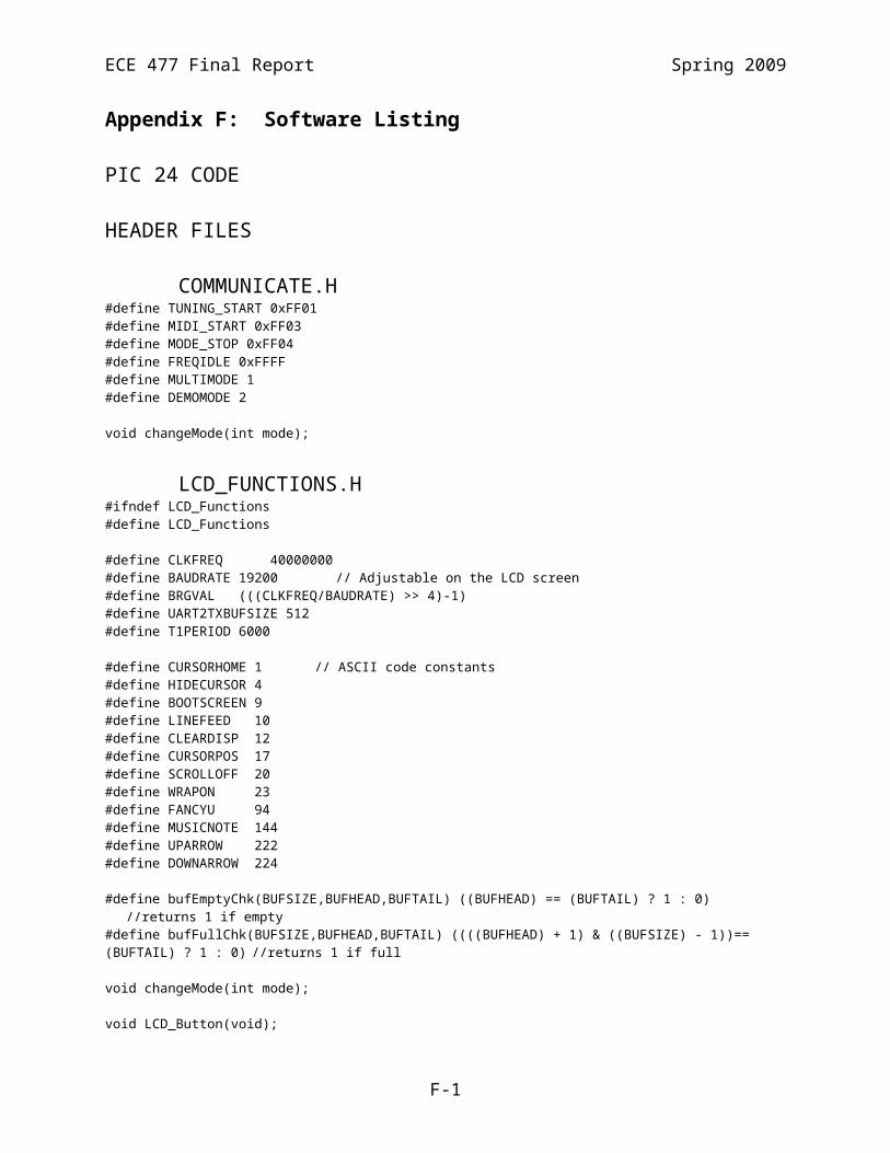
ECE 477 Final Report Spring 2009
uart2TxBufWr(CURSORPOS); uart2TxBufWr(0); uart2TxBufWr(3);
if (Menu_State == 22) { uart2TxBufWr(MUSICNOTE); } else { uart2TxBufWr(' '); }
uart2TxBufWr(CURSORPOS); uart2TxBufWr(11); uart2TxBufWr(1);
if (Menu_State == 23) { uart2TxBufWr(MUSICNOTE); } else { uart2TxBufWr(' '); }
uart2TxBufWr(CURSORPOS); uart2TxBufWr(11); uart2TxBufWr(2);
if (Menu_State == 24) { uart2TxBufWr(MUSICNOTE); } else { uart2TxBufWr(' '); }
uart2TxBufWr(CURSORPOS); uart2TxBufWr(11); uart2TxBufWr(3);
if (Menu_State == 25) { uart2TxBufWr(MUSICNOTE); } else { uart2TxBufWr(' '); }}
void LCD_User(unsigned int New) { if (New == 1) { uart2TxBufWr(CLEARDISP);
uart2TxBufWr(CURSORPOS); uart2TxBufWr(2); uart2TxBufWr(1); uart2TxBufWrStr("Tune with User ", 15); uart2TxBufWr(User_Selection + 48);
uart2TxBufWr(CURSORPOS); uart2TxBufWr(2); uart2TxBufWr(2); uart2TxBufWrStr("Edit User ", 10); uart2TxBufWr(User_Selection + 48); }
uart2TxBufWr(CURSORPOS); uart2TxBufWr(1); uart2TxBufWr(1);
if (Menu_State == 30) { uart2TxBufWr(MUSICNOTE);
F-29

ECE 477 Final Report Spring 2009
} else { uart2TxBufWr(' '); }
uart2TxBufWr(CURSORPOS); uart2TxBufWr(1); uart2TxBufWr(2);
if (Menu_State == 31) { uart2TxBufWr(MUSICNOTE); } else { uart2TxBufWr(' '); }}
void LCD_Edit(unsigned int New) { if (New == 1) { uart2TxBufWr(CLEARDISP);
uart2TxBufWrStr("User ", 5); uart2TxBufWr(User_Selection + 48); uart2TxBufWr(CURSORPOS); uart2TxBufWr(8); uart2TxBufWr(0); uart2TxBufWr(UPARROW); uart2TxBufWr(' '); uart2TxBufWr(UPARROW); uart2TxBufWr(' '); uart2TxBufWr(UPARROW); uart2TxBufWr(' '); uart2TxBufWr(UPARROW); uart2TxBufWr(' '); uart2TxBufWr(UPARROW); uart2TxBufWr(' '); uart2TxBufWr(UPARROW);
uart2TxBufWr(CURSORPOS); uart2TxBufWr(1); uart2TxBufWr(1); uart2TxBufWrStr("Edit", 4);
uart2TxBufWr(CURSORPOS); uart2TxBufWr(1); uart2TxBufWr(2); uart2TxBufWrStr("Save ", 7); uart2TxBufWr(DOWNARROW); uart2TxBufWr(' '); uart2TxBufWr(DOWNARROW); uart2TxBufWr(' '); uart2TxBufWr(DOWNARROW); uart2TxBufWr(' '); uart2TxBufWr(DOWNARROW); uart2TxBufWr(' '); uart2TxBufWr(DOWNARROW); uart2TxBufWr(' '); uart2TxBufWr(DOWNARROW);
uart2TxBufWr(CURSORPOS); uart2TxBufWr(1); uart2TxBufWr(3); uart2TxBufWrStr("Default", 7); }
uart2TxBufWr(CURSORPOS);
F-30

ECE 477 Final Report Spring 2009
uart2TxBufWr(0); uart2TxBufWr(1);
if (Menu_State == 40) { uart2TxBufWr(MUSICNOTE); } else { uart2TxBufWr(' '); }
uart2TxBufWr(CURSORPOS); uart2TxBufWr(0); uart2TxBufWr(2);
if (Menu_State == 41) { uart2TxBufWr(MUSICNOTE); } else { uart2TxBufWr(' '); }
uart2TxBufWr(CURSORPOS); uart2TxBufWr(0); uart2TxBufWr(3);
if (Menu_State == 42) { uart2TxBufWr(MUSICNOTE); } else { uart2TxBufWr(' '); }
uart2TxBufWr(CURSORPOS); uart2TxBufWr(8); uart2TxBufWr(3);
if (Menu_State == 43) { uart2TxBufWr(MUSICNOTE); } else { uart2TxBufWr(' '); }
uart2TxBufWr(' ');
if (Menu_State == 44) { uart2TxBufWr(MUSICNOTE); } else { uart2TxBufWr(' '); }
uart2TxBufWr(' ');
if (Menu_State == 45) { uart2TxBufWr(MUSICNOTE); } else { uart2TxBufWr(' '); }
uart2TxBufWr(' ');
if (Menu_State == 46) { uart2TxBufWr(MUSICNOTE); } else { uart2TxBufWr(' '); }
uart2TxBufWr(' ');
F-31

ECE 477 Final Report Spring 2009
if (Menu_State == 47) { uart2TxBufWr(MUSICNOTE); } else { uart2TxBufWr(' '); }
uart2TxBufWr(' ');
if (Menu_State == 48) { uart2TxBufWr(MUSICNOTE); } else { uart2TxBufWr(' '); }
uart2TxBufWr(CURSORPOS); uart2TxBufWr(8); uart2TxBufWr(1);
uart2TxBufWr(String_Values[0][tuning_array[User_Selection*6]][0]); uart2TxBufWr(String_Values[0][tuning_array[User_Selection*6]][1]);
uart2TxBufWr(String_Values[1][tuning_array[User_Selection*6+1]][0]); uart2TxBufWr(String_Values[1][tuning_array[User_Selection*6+1]][1]);
uart2TxBufWr(String_Values[2][tuning_array[User_Selection*6+2]][0]); uart2TxBufWr(String_Values[2][tuning_array[User_Selection*6+2]][1]);
uart2TxBufWr(String_Values[3][tuning_array[User_Selection*6+3]][0]); uart2TxBufWr(String_Values[3][tuning_array[User_Selection*6+3]][1]);
uart2TxBufWr(String_Values[4][tuning_array[User_Selection*6+4]][0]); uart2TxBufWr(String_Values[4][tuning_array[User_Selection*6+4]][1]);
uart2TxBufWr(String_Values[5][tuning_array[User_Selection*6+5]][0]); uart2TxBufWr(String_Values[5][tuning_array[User_Selection*6+5]][1]);}
void LCD_Tune(unsigned int New) { if (New == 1) { uart2TxBufWr(CLEARDISP); }
if (Menu_State == 50) { if (New == 1) { changeMode(TUNING_START);
uart2TxBufWrStr(" 1 2 3 4 5 6", 17); uart2TxBufWr(CURSORPOS); uart2TxBufWr(0); uart2TxBufWr(2); uart2TxBufWrStr("Current:", 8); uart2TxBufWr(CURSORPOS); uart2TxBufWr(0); uart2TxBufWr(3); uart2TxBufWrStr("Setting:", 8); }
uart2TxBufWr(CURSORPOS); uart2TxBufWr(1); uart2TxBufWr(1);
if (motor_state == 0) { if (String_State[0] == 1) {
F-32

ECE 477 Final Report Spring 2009
uart2TxBufWr(UPARROW); } else if (String_State[0] == 0) { uart2TxBufWr('-'); } else if (String_State[0] == -1) { uart2TxBufWr(DOWNARROW); } } else { uart2TxBufWr(' '); }
uart2TxBufWr(' '); uart2TxBufWr(' ');
if (motor_state == 1) { if (String_State[1] == 1) { uart2TxBufWr(UPARROW); } else if (String_State[1] == 0){ uart2TxBufWr('-'); } else if (String_State[1] == -1){ uart2TxBufWr(DOWNARROW); } } else { uart2TxBufWr(' '); }
uart2TxBufWr(' '); uart2TxBufWr(' ');
if (motor_state == 2){ if (String_State[2] == 1){ uart2TxBufWr(UPARROW); } else if (String_State[2] == 0){ uart2TxBufWr('-'); } else if (String_State[2] == -1){ uart2TxBufWr(DOWNARROW); } } else { uart2TxBufWr(' '); }
uart2TxBufWr(' '); uart2TxBufWr(' ');
if (motor_state == 3){ if (String_State[3] == 1){ uart2TxBufWr(UPARROW); } else if (String_State[3] == 0){ uart2TxBufWr('-'); } else if (String_State[3] == -1){ uart2TxBufWr(DOWNARROW); } } else { uart2TxBufWr(' '); }
uart2TxBufWr(' ');
F-33

ECE 477 Final Report Spring 2009
uart2TxBufWr(' ');
if (motor_state == 4){ if (String_State[4] == 1) { uart2TxBufWr(UPARROW); } else if (String_State[4] == 0){ uart2TxBufWr('-'); } else if (String_State[4] == -1){ uart2TxBufWr(DOWNARROW); } } else { uart2TxBufWr(' '); }
uart2TxBufWr(' '); uart2TxBufWr(' ');
if (motor_state == 5){ if (String_State[5] == 1){ uart2TxBufWr(UPARROW); } else if (String_State[5] == 0){ uart2TxBufWr('-'); } else if (String_State[5] == -1){ uart2TxBufWr(DOWNARROW); } } else { uart2TxBufWr(' '); }
uart2TxBufWr(CURSORPOS); uart2TxBufWr(9); uart2TxBufWr(2); uart2TxBufWr(freq_history[0][0]/100 + 48); uart2TxBufWr(freq_history[0][0]/10 - freq_history[0][0]/100*10 + 48); uart2TxBufWr(freq_history[0][0] - freq_history[0][0]/10*10 + 48);
uart2TxBufWr(CURSORPOS); uart2TxBufWr(9); uart2TxBufWr(3); uart2TxBufWr(Freq_Values[motor_state][tuning_array[User_Selection*6+motor_state]]/100 + 48); uart2TxBufWr(Freq_Values[motor_state][tuning_array[User_Selection*6+motor_state]]/10 - Freq_Values[motor_state][tuning_array[User_Selection*6+motor_state]]/100*10 + 48); uart2TxBufWr(Freq_Values[motor_state][tuning_array[User_Selection*6+motor_state]] - Freq_Values[motor_state][tuning_array[User_Selection*6+motor_state]]/10*10 + 48); }
else if (Menu_State == 51){ uart2TxBufWrStr("Autotune is complete", 20); uart2TxBufWrStr("returning to the", 16);
uart2TxBufWr(CURSORPOS); uart2TxBufWr(0); uart2TxBufWr(2); uart2TxBufWrStr("main menu.", 10); }
else if (Menu_State == 52){
F-34

ECE 477 Final Report Spring 2009
uart2TxBufWrStr("Autotune has failed.", 20); uart2TxBufWrStr("Please check motor ", 20); uart2TxBufWrStr("connections.", 12); }
}
void LCD_Transcribe(void) // Called when a change is made to Transcribing screens{ uart2TxBufWr(CLEARDISP);
if (Menu_State == 100){ uart2TxBufWrStr("Please insert an ", 20); uart2TxBufWrStr("acceptable flash ", 20); uart2TxBufWrStr("drive into the right", 20); uart2TxBufWrStr("side of the box.", 16); }
else if (Menu_State == 101){ uart2TxBufWr(CURSORPOS); uart2TxBufWr(5); uart2TxBufWr(1); uart2TxBufWrStr("Waiting...", 10);
uart2TxBufWr(CURSORPOS); uart2TxBufWr(2); uart2TxBufWr(2); uart2TxBufWr(MUSICNOTE); uart2TxBufWrStr("Start Recording", 15); }
else if (Menu_State == 102){ uart2TxBufWr(CURSORPOS); uart2TxBufWr(5); uart2TxBufWr(1); uart2TxBufWrStr("Recording", 9);
uart2TxBufWr(CURSORPOS); uart2TxBufWr(2); uart2TxBufWr(2); uart2TxBufWr(MUSICNOTE); uart2TxBufWrStr("Stop Recording", 14);
midi_file = MIDI_Create_File(DEFAULT_FNAME); transcribeFlag = 1; //Back to the main loop //until we're done recording. changeMode(MIDI_START); }
else if (Menu_State == 103){ changeMode(MODE_STOP);
uart2TxBufWrStr("Writing MIDI file to", 20); uart2TxBufWrStr("flash drive and", 15);
uart2TxBufWr(CURSORPOS); uart2TxBufWr(0); uart2TxBufWr(2);
uart2TxBufWrStr("returning to the", 16);
uart2TxBufWr(CURSORPOS); uart2TxBufWr(0); uart2TxBufWr(3);
F-35

ECE 477 Final Report Spring 2009
uart2TxBufWrStr("main menu.", 10);
//Finalize MIDI file if (MIDI_Finalize(midi_file) == USB_SUCCESS) { transcribeFlag = 0; Menu_State = 10; LCD_Main(1); return; } }}
void LCD_PSSC(unsigned int New) { // PSSC demo screen if (New == 1) { uart2TxBufWr(CLEARDISP);
uart2TxBufWrStr("Which one?", 10);
uart2TxBufWr(CURSORPOS); uart2TxBufWr(2); uart2TxBufWr(1); uart2TxBufWrStr("Motors FLASH", 14);
uart2TxBufWr(CURSORPOS); uart2TxBufWr(2); uart2TxBufWr(2); uart2TxBufWrStr("Sound UI", 11);
uart2TxBufWr(CURSORPOS); uart2TxBufWr(2); uart2TxBufWr(3); uart2TxBufWrStr("USB", 3); }
uart2TxBufWr(CURSORPOS); uart2TxBufWr(1); uart2TxBufWr(1);
if (Menu_State == 200) { uart2TxBufWr(MUSICNOTE); } else{ uart2TxBufWr(' '); }
uart2TxBufWr(CURSORPOS); uart2TxBufWr(1); uart2TxBufWr(2);
if (Menu_State == 201) { uart2TxBufWr(MUSICNOTE); } else { uart2TxBufWr(' '); }
uart2TxBufWr(CURSORPOS); uart2TxBufWr(1); uart2TxBufWr(3);
if (Menu_State == 202) { uart2TxBufWr(MUSICNOTE); } else { uart2TxBufWr(' '); }
F-36

ECE 477 Final Report Spring 2009
uart2TxBufWr(CURSORPOS); uart2TxBufWr(10); uart2TxBufWr(1);
if (Menu_State == 203) { uart2TxBufWr(MUSICNOTE); } else { uart2TxBufWr(' '); }
uart2TxBufWr(CURSORPOS); uart2TxBufWr(10); uart2TxBufWr(2);
if (Menu_State == 204) { uart2TxBufWr(MUSICNOTE); } else { uart2TxBufWr(' '); }}
void LCD_Motors(unsigned int New) { if (New == 1) { uart2TxBufWr(CLEARDISP);
uart2TxBufWr(CURSORPOS); uart2TxBufWr(1); uart2TxBufWr(1); uart2TxBufWrStr("1 2 3 4 5 6", 16);
uart2TxBufWr(CURSORPOS); uart2TxBufWr(1); uart2TxBufWr(2); uart2TxBufWr('C'); uart2TxBufWr('W');
uart2TxBufWr(CURSORPOS); uart2TxBufWr(7); uart2TxBufWr(2); uart2TxBufWr('C'); uart2TxBufWr('W');
uart2TxBufWr(CURSORPOS); uart2TxBufWr(13); uart2TxBufWr(2); uart2TxBufWr('C'); uart2TxBufWr('W');
uart2TxBufWr(CURSORPOS); uart2TxBufWr(4); uart2TxBufWr(3); uart2TxBufWr('C'); uart2TxBufWr('W');
uart2TxBufWr(CURSORPOS); uart2TxBufWr(10); uart2TxBufWr(3); uart2TxBufWr('C'); uart2TxBufWr('W');
uart2TxBufWr(CURSORPOS); uart2TxBufWr(16); uart2TxBufWr(3);
F-37

ECE 477 Final Report Spring 2009
uart2TxBufWr('C'); uart2TxBufWr('W'); }
uart2TxBufWr(CURSORPOS); uart2TxBufWr(1); uart2TxBufWr(0);
if (Menu_State == 210) { uart2TxBufWr(MUSICNOTE); } else { uart2TxBufWr(' '); }
uart2TxBufWr(' '); uart2TxBufWr(' ');
if (Menu_State == 211) { uart2TxBufWr(MUSICNOTE); } else { uart2TxBufWr(' '); }
uart2TxBufWr(' '); uart2TxBufWr(' ');
if (Menu_State == 212) { uart2TxBufWr(MUSICNOTE); } else { uart2TxBufWr(' '); }
uart2TxBufWr(' '); uart2TxBufWr(' ');
if (Menu_State == 213) { uart2TxBufWr(MUSICNOTE); } else { uart2TxBufWr(' '); }
uart2TxBufWr(' '); uart2TxBufWr(' ');
if (Menu_State == 214) { uart2TxBufWr(MUSICNOTE); } else { uart2TxBufWr(' '); }
uart2TxBufWr(' '); uart2TxBufWr(' ');
if (Menu_State == 215) { uart2TxBufWr(MUSICNOTE); } else { uart2TxBufWr(' '); }
uart2TxBufWr(CURSORPOS); uart2TxBufWr(0); uart2TxBufWr(2);
if (String_State[0] == 1) {
F-38
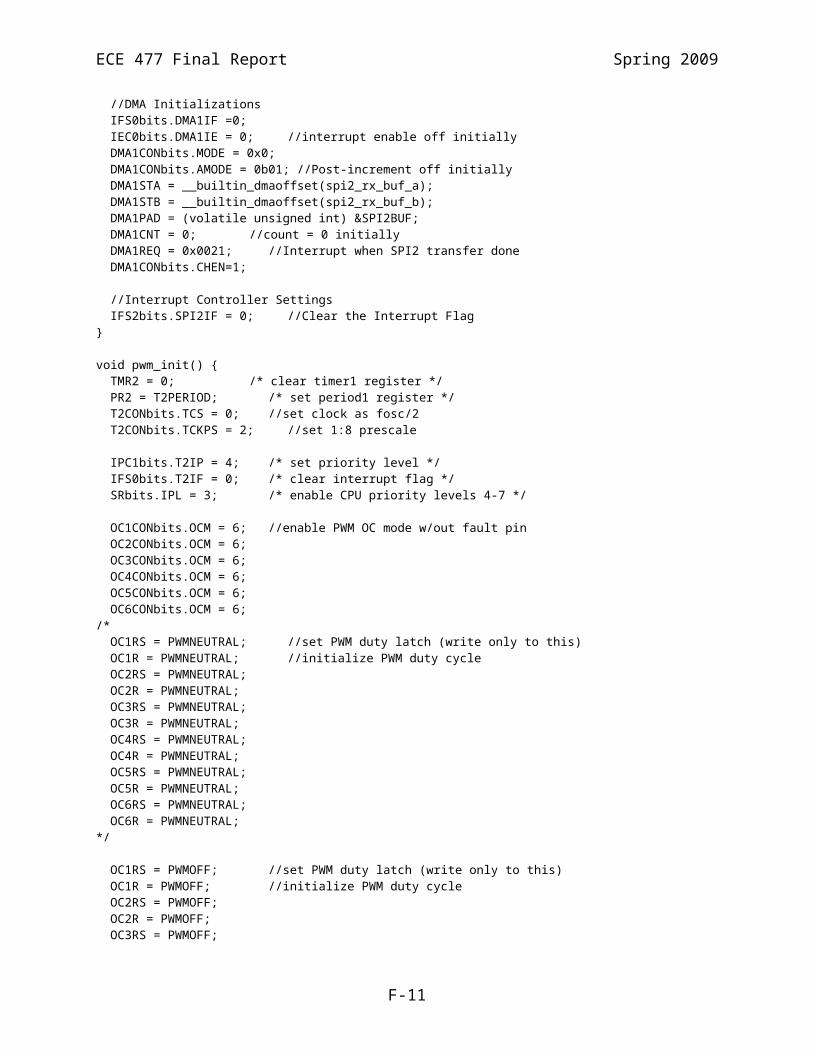
ECE 477 Final Report Spring 2009
uart2TxBufWr(' '); OC1RS = PWMNEUTRAL + 25; } else { uart2TxBufWr('C'); OC1RS = PWMNEUTRAL - 25; }
uart2TxBufWr(CURSORPOS); uart2TxBufWr(6); uart2TxBufWr(2);
if (String_State[2] == 1) { uart2TxBufWr(' '); OC3RS = PWMNEUTRAL + 25; } else { uart2TxBufWr('C'); OC3RS = PWMNEUTRAL - 25; }
uart2TxBufWr(CURSORPOS); uart2TxBufWr(12); uart2TxBufWr(2);
if (String_State[4] == 1) { uart2TxBufWr(' '); OC5RS = PWMNEUTRAL + 25; } else { uart2TxBufWr('C'); OC5RS = PWMNEUTRAL - 25; }
uart2TxBufWr(CURSORPOS); uart2TxBufWr(3); uart2TxBufWr(3);
if (String_State[1] == 1) { uart2TxBufWr(' '); OC2RS = PWMNEUTRAL + 25; } else { uart2TxBufWr('C'); OC2RS = PWMNEUTRAL - 25; }
uart2TxBufWr(CURSORPOS); uart2TxBufWr(9); uart2TxBufWr(3);
if (String_State[3] == 1) { uart2TxBufWr(' '); OC4RS = PWMNEUTRAL + 25; } else { uart2TxBufWr('C'); OC4RS = PWMNEUTRAL - 25; }
uart2TxBufWr(CURSORPOS); uart2TxBufWr(15); uart2TxBufWr(3);
if (String_State[5] == 1) { uart2TxBufWr(' '); OC6RS = PWMNEUTRAL + 25; } else { uart2TxBufWr('C');
F-39

ECE 477 Final Report Spring 2009
OC6RS = PWMNEUTRAL - 25; }}
void LCD_Sound(unsigned int New) { if (New == 1) { changeMode(DEMOMODE); uart2TxBufWr(CLEARDISP);
uart2TxBufWrStr("Frequency peaks at 1.", 22);
uart2TxBufWr(CURSORPOS); uart2TxBufWr(10); uart2TxBufWr(1); uart2TxBufWr('4'); uart2TxBufWr('.');
uart2TxBufWr(CURSORPOS); uart2TxBufWr(0); uart2TxBufWr(2); uart2TxBufWr('2'); uart2TxBufWr('.');
uart2TxBufWr(CURSORPOS); uart2TxBufWr(10); uart2TxBufWr(2); uart2TxBufWr('5'); uart2TxBufWr('.');
uart2TxBufWr(CURSORPOS); uart2TxBufWr(0); uart2TxBufWr(3); uart2TxBufWr('3'); uart2TxBufWr('.');
uart2TxBufWr(CURSORPOS); uart2TxBufWr(10); uart2TxBufWr(3); uart2TxBufWr('6'); uart2TxBufWr('.'); }
uart2TxBufWr(CURSORPOS); uart2TxBufWr(3); uart2TxBufWr(1); uart2TxBufWr(freq_history[0][0]/100 + 48); uart2TxBufWr(freq_history[0][0]/10 - freq_history[0][0]/100*10 + 48); uart2TxBufWr(freq_history[0][0] - freq_history[0][0]/10*10 + 48);
uart2TxBufWr(CURSORPOS); uart2TxBufWr(13); uart2TxBufWr(1); uart2TxBufWr(freq_history[0][3]/100 + 48); uart2TxBufWr(freq_history[0][3]/10 - freq_history[0][3]/100*10 + 48); uart2TxBufWr(freq_history[0][3] - freq_history[0][3]/10*10 + 48);
uart2TxBufWr(CURSORPOS); uart2TxBufWr(3); uart2TxBufWr(2); uart2TxBufWr(freq_history[0][1]/100 + 48); uart2TxBufWr(freq_history[0][1]/10 - freq_history[0][1]/100*10 + 48); uart2TxBufWr(freq_history[0][1] - freq_history[0][1]/10*10 + 48);
uart2TxBufWr(CURSORPOS);
F-40

ECE 477 Final Report Spring 2009
uart2TxBufWr(13); uart2TxBufWr(2); uart2TxBufWr(freq_history[0][4]/100 + 48); uart2TxBufWr(freq_history[0][4]/10 - freq_history[0][4]/100*10 + 48); uart2TxBufWr(freq_history[0][4] - freq_history[0][4]/10*10 + 48);
uart2TxBufWr(CURSORPOS); uart2TxBufWr(3); uart2TxBufWr(3); uart2TxBufWr(freq_history[0][2]/100 + 48); uart2TxBufWr(freq_history[0][2]/10 - freq_history[0][2]/100*10 + 48); uart2TxBufWr(freq_history[0][2] - freq_history[0][2]/10*10 + 48);
uart2TxBufWr(CURSORPOS); uart2TxBufWr(13); uart2TxBufWr(3); uart2TxBufWr(freq_history[0][5]/100 + 48); uart2TxBufWr(freq_history[0][5]/10 - freq_history[0][5]/100*10 + 48); uart2TxBufWr(freq_history[0][5] - freq_history[0][5]/10*10 + 48);}
void LCD_USB(void) { int i, j; file_desc *file; int status = 0x2; char response[200]; int resLen;
//Clear all previous statuses status = usbStatusRead(); while (status & 0x2) { usbResponseDelay(); resLen = usbInitRead(response, 200); if (resLen == 0) break; status = usbStatusRead(); for (i=0;i<20;i++) { usbResponseDelay(); } }
uart2TxBufWr(CLEARDISP);
if (Menu_State == 230) { uart2TxBufWrStr("Please insert an ", 20); uart2TxBufWrStr("acceptable flash ", 20); uart2TxBufWrStr("drive into the right", 20); uart2TxBufWrStr("side of the box.", 16); } else if (Menu_State == 231) { uart2TxBufWr(CURSORPOS); uart2TxBufWr(0); uart2TxBufWr(1);
uart2TxBufWrStr("Writing sample MIDI ", 20); uart2TxBufWrStr("file to flash drive.", 20); if ( (file = MIDI_Create_File(PSSC_FNAME)) == NULL) { asm volatile("nop"); uart2TxBufWr(CLEARDISP); uart2TxBufWr(CURSORPOS); uart2TxBufWr(0); uart2TxBufWr(1); uart2TxBufWrStr("ERROR", 5); //Delay...
F-41

ECE 477 Final Report Spring 2009
for (i=0;i<20000;i++) { for (j=0;j<150;j++) {} } Menu_State = 10; LCD_Main(1); return; }
if ( (MIDI_Form_Demo()) != 1 ) { asm volatile("nop"); uart2TxBufWr(CLEARDISP); uart2TxBufWr(CURSORPOS); uart2TxBufWr(0); uart2TxBufWr(1); uart2TxBufWrStr("ERROR", 5); //Delay... for (i=0;i<20000;i++) { for (j=0;j<150;j++) {} } Menu_State = 10; LCD_Main(1); return; }
if ( MIDI_Finalize(file) == USB_FAIL) { uart2TxBufWr(CLEARDISP); uart2TxBufWr(CURSORPOS); uart2TxBufWr(0); uart2TxBufWr(1); uart2TxBufWrStr("ERROR", 5); //Delay... for (i=0;i<20000;i++) { for (j=0;j<150;j++) {} } Menu_State = 10; LCD_Main(1); return; } Menu_State = 10; LCD_Main(1); }}
void LCD_FLASH(unsigned int New) { if (New == 1) { uart2TxBufWr(CLEARDISP);
uart2TxBufWr(CURSORPOS); uart2TxBufWr(1); uart2TxBufWr(1);
uart2TxBufWrStr("Value in FLASH: ", 16); uart2TxBufWr(*flash_pssc + 48);
uart2TxBufWr(CURSORPOS); uart2TxBufWr(1); uart2TxBufWr(2); uart2TxBufWrStr("Value to store: ", 17); }
uart2TxBufWr(27); uart2TxBufWr(91); uart2TxBufWr(68); uart2TxBufWr(*flash_pssc + 48);
F-42

ECE 477 Final Report Spring 2009
}
void LCD_UI(unsigned int New) { if (New == 1) { tunings_from_flash();
uart2TxBufWr(CLEARDISP); uart2TxBufWrStr("User Setting", 12);
uart2TxBufWr(CURSORPOS); uart2TxBufWr(1); uart2TxBufWr(1); uart2TxBufWrStr("1 2 3 4 5 6", 17); }
uart2TxBufWr(CURSORPOS); uart2TxBufWr(13); uart2TxBufWr(0); uart2TxBufWr(Menu_State - 249 + 48);
uart2TxBufWr(CURSORPOS); uart2TxBufWr(1); uart2TxBufWr(2); uart2TxBufWr(String_Values[0][tuning_array[(Menu_State-249)*6]][0]); uart2TxBufWr(String_Values[0][tuning_array[(Menu_State-249)*6]][1]); uart2TxBufWr(' '); uart2TxBufWr(String_Values[1][tuning_array[(Menu_State-249)*6+1]][0]); uart2TxBufWr(String_Values[1][tuning_array[(Menu_State-249)*6+1]][1]); uart2TxBufWr(' '); uart2TxBufWr(String_Values[2][tuning_array[(Menu_State-249)*6+2]][0]); uart2TxBufWr(String_Values[2][tuning_array[(Menu_State-249)*6+2]][1]); uart2TxBufWr(' '); uart2TxBufWr(String_Values[3][tuning_array[(Menu_State-249)*6+3]][0]); uart2TxBufWr(String_Values[3][tuning_array[(Menu_State-249)*6+3]][1]); uart2TxBufWr(' '); uart2TxBufWr(String_Values[4][tuning_array[(Menu_State-249)*6+4]][0]); uart2TxBufWr(String_Values[4][tuning_array[(Menu_State-249)*6+4]][1]); uart2TxBufWr(' '); uart2TxBufWr(String_Values[5][tuning_array[(Menu_State-249)*6+5]][0]); uart2TxBufWr(String_Values[5][tuning_array[(Menu_State-249)*6+5]][1]);}
MIDI.C// Based on Norman Hardy's MIDI code. // http://www.cap-lore.com/EnglishSuites/code/code.html// Hacked together with http://www.sphere.ws/blog/?p=33
#include "p24HJ128GP306.h"#include "LCD_Functions.h"#include "uart.h"#include "usb_funcs.h"#include "communicate.h"#include <string.h>#include "midi.h"
typedef unsigned int ui;
int dsize;int rdindex;int wrindex;int midi_trkindex;int bytecnt;
F-43

ECE 477 Final Report Spring 2009
char midi[BUFFER_SIZE] __attribute__((far));const char note[32] = {60, 62, 64, 60, 60, 62, 64, 60, 64, 65, 67, 64, 65, 67, 67, 69, 67, 65, 64, 60, 67, 69, 67, 65, 64, 60, 60, 55, 60, 60, 55, 60};
const char dura[32] = {2, 2, 2, 2, 2, 2, 2, 2, 2, 2, 4, 2, 2, 4, 1, 1, 1, 1, 2, 2, 1, 1, 1, 1, 2, 2, 2, 2, 4, 2, 2, 4};
void midi_init(void) { dsize = 0; rdindex = 0; wrindex = -1; midi_trkindex = 0; bytecnt = 0;}
// Deposits character in buffer if there is roomvoid pushc(char x){ if(++wrindex >= BUFFER_SIZE) wrindex = 0; midi[wrindex] = x; bytecnt++; dsize++;}
void pullc(void){ if(++rdindex >= BUFFER_SIZE) rdindex = 0; dsize--;}
// Deposits binary v in c bytesvoid pn(int c, ui v) { if(c) { pn(c - 1, v >> 8); pushc(v & 255); }}
// Routine for depositing variable length binary numbersvoid pvlr(ui n) { if(n > 127) pvlr(n >> 7); pushc(0x80 | (n & 127));}
// Routine for depositing variable length binary numbersvoid pvl(ui n) { if(n > 127) pvlr(n >> 7); pushc(n & 127);}
// Plays note n for duration dvoid n(int n, int d){ if (n <= 0x21){ // plays a rest pushc(0); pushc(0); pvl(d); pushc(0); pushc(0); pvl(0); } else { pushc(n); // Emit note value
F-44

ECE 477 Final Report Spring 2009
pushc(64); // Standard loudness pvl(d);//*120); // dt for note duration pushc(n); // Write note to stop pushc(0); // loudness = 0 to stop pvl(0); // Emit dt }}
file_desc *MIDI_Create_File(char *fname) { int fname_len; int data_len; file_desc *file;
fname_len = strlen(fname);
// Creates the header for the MIDI file pushc(0x4d); // don't change pushc(0x54); // don't change pushc(0x68); // don't change pushc(0x64); // don't change pn(4, 6); // don't change pn(2, 0); // 0 = single track, 1 = synchronous multiple tracks pn(2, 1); // number of tracks in the file pn(2, 240); // number of delta time ticks per quarter note
// Start of a track pushc(0x4d); // don't change pushc(0x54); // don't change pushc(0x72); // don't change pushc(0x6B); midi_trkindex = bytecnt; bytecnt = 0;
data_len = dsize; file = file_open(fname, fname_len, 'w');
while (data_len != 0) { if ((file_write(file, &(midi[rdindex]), 1)) != USB_FAIL){ pullc(); data_len--; } } return file;}
int MIDI_Form_Demo(void){ int data_index = 0;
for (data_index=0; data_index < 32; data_index++){ n(note[data_index],dura[data_index]*120); } return 1;}
int MIDI_Finalize(file_desc *fd){ int close_status; int rdindex_old; int wrindex_old; int dsize_old;
pushc(0xFF); pushc(0x2F); pvl(0);
F-45

ECE 477 Final Report Spring 2009
rdindex_old = rdindex; wrindex_old = wrindex; dsize_old = dsize; rdindex = wrindex+1; dsize = 0;
pn(4, bytecnt+5); // placeholder bytes for track size pushc(0); pushc(0xc0); pushc(1); // voice (instrument heard on MIDI) pvl(0); pushc(0x90); // note down, channel 1
// prints out the rest of the header while (dsize > 0){ if ((file_write(fd, &(midi[rdindex]), 1)) == USB_SUCCESS) pullc(); }
rdindex = rdindex_old; wrindex = wrindex_old; dsize = dsize_old;
// Prints out the rest of the buffer; while (dsize > 0){ if ((file_write(fd, &(midi[rdindex]), 1)) == USB_SUCCESS) pullc(); }
close_status = file_close(fd); return close_status;}
READ_FLASH.S.text.global _read_flash_byte
_read_flash_byte:MOV #tblpage(0x800),W2 ; get table page valueMOV W2,TBLPAG ; load TBLPAG register with W2MOV W0,W2 ; Load W2 with prog mem offset pointer;TBLRDH.B [W2],W3 ; Read high byte to W3TBLRDL.B [W2++],W3 ; Read low byte of prog mem pointer into W3TBLRDL.B [W2++],W4 ; Read high byte to W5MOV #0x0008,W5SL W4,W5,W4MOV #0x00FF,W5AND W3,W5,W3IOR W4,W3,W4MOV W4,[W1] ; Write prog mem value in W3 to address in W1RETURN.end
usb_funcs.c#include "p24HJ128GP306.h"#include "LCD_Functions.h" //To get bufferfull, empty checks#include "usb_funcs.h"#include <string.h>
//command set//After each command, add a parameter, then append a newlineconst char BADCOMMAND[] = {0x42, 0x43};
F-46

ECE 477 Final Report Spring 2009
const char CD[] = {0x02, 0x20};const char RDF[] = {0x0B, 0x20}; //RDF dword_bytes CRconst char WRF[] = {0x08, 0x20}; //WRF dword_bytes CR dataconst char OPR[] = {0x0E, 0x20}; //OPR fname CRconst char OPW[] = {0x09, 0x20}; //OPW fname CRconst char CLF[] = {0x0A, 0x20}; //CLF CRconst char SEK[] = {0x28, 0x20}; //SEK dword_abs_pos CRconst char SCS[] = {0x10};const char DIR[] = {0x01};const char IPH[] = {0x91}; //Puts monitor in binary mode
//Global File Descriptor 'n suchfile_desc file1;file_desc* sysFile;
char usbCommandBuffer[USB_CMD_BUFF_SIZE];unsigned int usbCommandBufferHead;unsigned int usbCommandBufferTail;
void usb_init(void) { char bootVal[200]; char commandResponse[200]; int i, j, len, resLen; int status;
//Init file structure file1.pos = 0; file1.open = 0; file1.fname_len = 0; sysFile = &file1;
//Wait while the darn thing boots up for (i=0;i<3000;i++) { for (j=0;j<500;j++) { asm volatile("nop"); } } //Read initial USB status from the device len = usbInitRead(bootVal, 200);
//Send short character set command usbBufferWrite(SCS, 1); usbBufferWriteChar(CR); resLen = usbCommandSend(commandResponse, 200); usbBufferWrite(IPH, 1); usbBufferWriteChar(CR); resLen = usbCommandSend(commandResponse, 200);
//Clear all statuses status = usbStatusRead(); while (status & 0x2) { usbResponseDelay(); resLen = usbInitRead(commandResponse, 200); if (resLen == 0) break; asm volatile("nop"); status = usbStatusRead(); for (i=0;i<20;i++) { usbResponseDelay(); } } i++;}
F-47

ECE 477 Final Report Spring 2009
char usbStatusRead(void) { char status;
PORTBbits.RB2 = 1; SPI1BUF = (USB_HEADER | USB_STATUS_READ ); asm volatile("nop"); //Wait for SPI transmission to complete while (SPI1STATbits.SPITBF) {}; while (!SPI1STATbits.SPIRBF) {}; PORTBbits.RB2 = 0;
status = USB_OUTPUT_BYTE(SPI1BUF);
return status;}
int usbInitRead(char *resultBuf, int maxLen) { //Reads up to maxLen characters from the USB device. //This is useful for status registers, reading files, etc. int len = 0; int status = 0; int delayVal = 0;
//Put the Read bits in the buffer PORTBbits.RB2 = 1; SPI1BUF = (USB_HEADER | USB_DATA_READ );
while (len < maxLen) { //Put the Read bits in the buffer PORTBbits.RB2 = 1; SPI1BUF = (USB_HEADER | USB_DATA_READ ); asm volatile("nop"); //Wait for SPI transmission to complete while (SPI1STATbits.SPITBF) {}; while (!SPI1STATbits.SPIRBF) {}; PORTBbits.RB2 = 0; //Delay for at least one SPIClk Cycle for (delayVal=0;delayVal<ONE_SPI_CYCLE;delayVal++); {}; *resultBuf = USB_OUTPUT_BYTE(SPI1BUF);
//Read Status. Old data? if so, quit status = SPI1BUF & USB_STATUS_MASK; if (status) { //Old data, we don't want it. break; }
//inc len by one bit. len++; resultBuf++; } return len;}
char usbBufferReadChar(void) { //Returns a character from the USB buffer, if available //Otherwise, NULL is returned char readOut = NULL;
if ( !(bufEmptyChk(USB_CMD_BUFF_SIZE, usbCommandBufferHead, usbCommandBufferTail))){ readOut = usbCommandBuffer[usbCommandBufferTail]; usbCommandBufferTail = (usbCommandBufferTail + 1) & (USB_CMD_BUFF_SIZE - 1); } return readOut;
F-48

ECE 477 Final Report Spring 2009
}
int usbBufferWriteChar(char addToBuff) { while (bufFullChk(USB_CMD_BUFF_SIZE, usbCommandBufferHead, usbCommandBufferTail)){}; usbCommandBuffer[usbCommandBufferHead] = addToBuff; usbCommandBufferHead = (usbCommandBufferHead + 1) & (USB_CMD_BUFF_SIZE - 1);
return USB_SUCCESS;}
int usbBufferWriteInt(int addToBuff) { char buffVal;
//Write the int as two separate 8 bit values, most significant first. while (bufFullChk(USB_CMD_BUFF_SIZE, usbCommandBufferHead, usbCommandBufferTail)){}; buffVal = addToBuff >> 8; usbCommandBuffer[usbCommandBufferHead] = buffVal; usbCommandBufferHead = (usbCommandBufferHead + 1) & (USB_CMD_BUFF_SIZE - 1);
while (bufFullChk(USB_CMD_BUFF_SIZE, usbCommandBufferHead, usbCommandBufferTail)){}; buffVal = addToBuff & 0x00FF; usbCommandBuffer[usbCommandBufferHead] = buffVal; usbCommandBufferHead = (usbCommandBufferHead + 1) & (USB_CMD_BUFF_SIZE - 1);
return USB_SUCCESS;}
int usbBufferWriteLong(long addToBuff) { char buffVal;
while (bufFullChk(USB_CMD_BUFF_SIZE, usbCommandBufferHead, usbCommandBufferTail)){}; buffVal = addToBuff >> 24; usbCommandBuffer[usbCommandBufferHead] = buffVal; usbCommandBufferHead = (usbCommandBufferHead + 1) & (USB_CMD_BUFF_SIZE - 1);
while (bufFullChk(USB_CMD_BUFF_SIZE, usbCommandBufferHead, usbCommandBufferTail)){}; buffVal = (addToBuff >> 16) & 0x000000FF; usbCommandBuffer[usbCommandBufferHead] = buffVal; usbCommandBufferHead = (usbCommandBufferHead + 1) & (USB_CMD_BUFF_SIZE - 1);
while (bufFullChk(USB_CMD_BUFF_SIZE, usbCommandBufferHead, usbCommandBufferTail)){}; buffVal = (addToBuff >> 8) & 0x000000FF; usbCommandBuffer[usbCommandBufferHead] = buffVal; usbCommandBufferHead = (usbCommandBufferHead + 1) & (USB_CMD_BUFF_SIZE - 1);
while (bufFullChk(USB_CMD_BUFF_SIZE, usbCommandBufferHead, usbCommandBufferTail)){}; buffVal = addToBuff & 0x00FF; usbCommandBuffer[usbCommandBufferHead] = buffVal; usbCommandBufferHead = (usbCommandBufferHead + 1) & (USB_CMD_BUFF_SIZE - 1);
return USB_SUCCESS;}
int usbBufferWrite(char *string, int len) { //Write a string of up to maxLen chars into the buffer. Return bytes copied //on success, -1 on fail int cpyCount = 0; if (len > MAX_STRLEN) return USB_FAIL;
while (cpyCount < len) { if (usbBufferWriteChar(*string) == USB_FAIL) {
F-49

ECE 477 Final Report Spring 2009
return USB_FAIL; } cpyCount++; string++; } return cpyCount;}
int usbCommandSend(char *responseBuf, int maxLen) { char sendChar; char statusResp, dataResp[200]; int dataRespLen; int i; int error = 0; int delayVal, status, len=0;
//Write a command to USB do { sendChar = usbCommandBuffer[usbCommandBufferTail]; PORTBbits.RB2 = 1; SPI1BUF = (USB_HEADER | USB_DATA_WRITE | USB_INPUT_BYTE(sendChar)); while (SPI1STATbits.SPITBF) {}; while (!SPI1STATbits.SPIRBF) {}; PORTBbits.RB2 = 0; //Delay for at least one SPIClk Cycle for (delayVal=0;delayVal<ONE_SPI_CYCLE;delayVal++) {}; status = SPI1BUF & USB_STATUS_MASK; if (status) { //Not accepted, need to repeat loop asm volatile("nop"); usbResponseDelay(); statusResp = usbStatusRead(); usbResponseDelay(); if (statusResp == 0x01) { //RCV buffer full, TX buffer not empty dataRespLen = usbInitRead(dataResp, 200); if ((error = usbErrorCodeCheck(dataResp, dataRespLen)) != 0) { asm volatile("nop"); return USB_FAIL; }
for (i=0;i<200;i++) usbResponseDelay(); } continue; }
//Move head & tail usbBufferReadChar();
} while (!bufEmptyChk(USB_CMD_BUFF_SIZE, usbCommandBufferHead, usbCommandBufferTail));
asm volatile("nop");
//Delay some amount of time while (len == 0) { usbResponseDelay();
//Read Out response len = usbInitRead(responseBuf, maxLen);
F-50

ECE 477 Final Report Spring 2009
} return len;}
//Read Response
void usbResponseDelay(void) { int delayVal;
for (delayVal=0;delayVal<USB_COMMAND_DELAY;delayVal++) {};}
file_desc* file_open(char* fname, int fname_len, char mode) { char response[200]; int error, len;
asm volatile("nop"); if (fname_len > MAX_FNAME_LEN) return NULL;
//Copy fopen command to buffer if (mode == 'r') { usbBufferWrite(OPR, 2); } else if (mode == 'w') { usbBufferWrite(OPW, 2); } else return NULL;
usbBufferWrite(fname, fname_len); usbBufferWriteChar(CR);
//Read Response, match against errors len = usbCommandSend(response, 200); if ( (error = usbErrorCodeCheck(response, len)) != 0) return NULL;
asm volatile("nop");
//No error, seek to start of file usbBufferWrite(SEK, 2); usbBufferWriteInt(0); usbBufferWriteInt(0); usbBufferWriteChar(CR);
len = usbCommandSend(response, 200); if ( (error = usbErrorCodeCheck(response, len)) != 0) return NULL;
asm volatile("nop");
strncpy(file1.fname, fname, fname_len); file1.fname_len = fname_len; file1.open = 1; file1.pos = 0;
return sysFile;}
int file_close(file_desc *file) { char response[200]; int error, len;
//copy fclose command to buffer usbBufferWrite(CLF, 2); usbBufferWriteChar(CR);
F-51

ECE 477 Final Report Spring 2009
len = usbCommandSend(response, 200); if ( (error = usbErrorCodeCheck(response, len)) != 0) return USB_FAIL; file->open = 0; file->pos = 0; file->fname_len = 0; return USB_SUCCESS;}
int file_read(file_desc *file, char* data, int len) { //Assumes 'data' is big enough to contain len bytes int rLen; int error; if (!(file->open)) return USB_FAIL; usbBufferWrite(RDF, 2); usbBufferWriteInt(0); usbBufferWriteInt(len); //32 bit dword type usbBufferWriteChar(CR);
rLen = usbCommandSend(data, len);
if ( (error = usbErrorCodeCheck(data, rLen)) != 0) { return USB_FAIL; } file->pos += rLen - 1;
return rLen;}
int file_write(file_desc *file, char* data, int len) { int rLen; char response[200]; int error; int i;
if (!(file->open)) return USB_FAIL;
usbBufferWrite(WRF, 2); usbBufferWriteInt(0); usbBufferWriteInt(len); usbBufferWriteChar(CR);
asm volatile("nop"); for (i=0;i<len;i++) usbBufferWriteChar(data[i]);
rLen = usbCommandSend(response, 200);
if ( (error = usbErrorCodeCheck(response, rLen)) != 0 ) { return USB_FAIL; } return USB_SUCCESS;}
int file_seek(file_desc *file, int position, int offset) { int rLen; char response[200]; int error;
asm volatile("nop"); usbBufferWrite(SEK, 2);
F-52

ECE 477 Final Report Spring 2009
switch (position) { case CURRENT: offset += (int)file->pos; case BEGIN: default: usbBufferWriteInt(0); usbBufferWriteInt(offset); }
usbBufferWriteChar(CR); rLen = usbCommandSend(response, 200);
if ( (error = usbErrorCodeCheck(response, rLen)) != 0 ) { return USB_FAIL; } return USB_SUCCESS;}
int usbErrorCodeCheck(char *input, int len) { if (input[0] == 0x43 && input[1] == 0x46 && input[2] == 0x0D && len == 3) return 1; //COMMANDFAIL else if (input[0] == 0x4E && input[1] == 0x44 && input[2] == 0x0D && len == 3) return 1; //NO DISK else if (input[0] == 0x44 && input[1] == 0x46 && input[2] == 0x0D && len == 3) return 1; //DISKFULL else if (input[0] == 0x46 && input[1] == 0x49 && input[2] == 0x0D && len == 3) return 1; //INVALID else if (input[0] == 0x52 && input[1] == 0x4f && input[2] == 0x0D && len == 3) return 1; //READONLY else if (input[0] == 0x46 && input[1] == 0x4f && input[2] == 0x0D && len == 3) return 1; //FILEOPEN else if (input[0] == 0x4e && input[1] == 0x45 && input[2] == 0x0D && len == 3) return 1; //DIRNOTEMPTY else if (input[0] == 0x46 && input[1] == 0x4e && input[2] == 0x0D && len == 3) return 1; //INVALIDFNAME else if (input[0] == 0x4e && input[1] == 0x55 && input[2] == 0x0D
F-53

ECE 477 Final Report Spring 2009
&& len == 3) return 1; //NOUPGRADE
return 0;}
DSPIC CODE
HEADER FILES
ADCroutines.h/******* DSP code for ECE 477 Team 4 (das Autotunr)** Initial version: March 6, 2009* Author(s): Joe Blubaugh******/
#ifndef ADCROUTINES#define ADCROUTINES
#define ADC_WINDOW_SIZE 16#define ADC_AVG_FILTER_SIZE 16#define ADC_ONE_OVER_FILTER_LEN 0x1000 //0.0625 = 2^-4#define ADC_WINDOW_SIZE_LOG2 4#define ADC_VECTOR_SIZE 1024 //was 1024#define ADC_HALF_VECTOR_SIZE 512#define ADC_VECTOR_SIZE_LOG2 10 //was 10#define ADC_NUM_SAMPLES 102 //was 102#define ADC_TIMER2_PRESCALE 0b00#define ADC_TIMER3_PERIOD 0#define ADC_TIMER2_PERIOD 9765 //was 9639#define ADC_TIMER4_PRESCALE 0b11#define ADC_TIMER4_PERIOD 9712 //every .0625 secs#define ADC_TUNING_MODE 0#define ADC_MIDI_MODE 1#define ADC_NEUTRAL_MODE 2#define ADC_PICK_DISCARD 128#define ADC_TUNING_DIVIDE 4 //was 4#define ADC_TUNING_DIVIDE_LOG2 2#define ADC_STARTUP_DIVIDE 20#define ADC_MIDI_DIVIDE 1#define ADC_MIDI_DIVIDE_LOG2 0#define ADC_MONITOR_STATE 0#define ADC_SAMPLE_STATE_PICK 1#define ADC_SAMPLE_STATE 2#define ADC_STARTUP_STATE 3#define ADC_FFT_READY_STATE 4#define ADC_FINISHED_STATE 5#define ADC_SAMPLE_THRESH 0x1800 //0.1875
#define ADC_MICROPHONE 0x0004
#define ADC_SCALE_FACT 0x5000 //Empirically determined scale factor to keep //values between -.5 and .5
#define HALF 0x3B00 //Cut it down below -0.5 to 0.5 and see if this helps#define NUM_NOTES 15
F-54

ECE 477 Final Report Spring 2009
#define SUB_AUDIBLE 40#define PEAK_SQUASH_WIDTH 10#define SECOND_HARM_SQUASH_WIDTH 6#define SECOND_HARM_INDEX_THRESH 200#define SECOND_HARM_MAG_THRESH 0x0290#define PEAK_THRESH 0x0180#define TUNING_MAX_FREQ 490#define MIDI_MAX_FREQ 490#define MIDI_FREQ_SHIFT 2 //times 4#define BASE_FREQ_THRESH 0x0290 //0.02002#define BASE_FREQ_SEARCH_WIDTH 12#define MAX_DERIV_WIDTH 16#define NOTE_MAG_THRESH 0x2000 //0.125#define ERR20_THRESH 3#define ERR15_THRESH 2#define SPI_PKT_SIZE 8#define SPI_START_PKT 0xFFFF#define SPI_END_PKT 0x7777
#define MIDI_START 0xFF03#define TUNING_START 0xFF01#define MODE_STOP 0xFF04
#define MODE_CHANGE_DELAY 100
typedef int noteAvg[2];typedef noteAvg notePack[8];
#define MAX(x, y) (x) > (y) ? (x) : (y)#define MIN(x, y) (x) > (y) ? (y) : (x)
void spi1_init(void);void initADC(void);void initTimer(void);void initOSC(void);void ADCChangeMode(int message);void __attribute__((__interrupt__, shadow, auto_psv)) _ADC1Interrupt(void);void __attribute__((__interrupt__, shadow, auto_psv)) _T3Interrupt(void);#endif
peakDetection.h#ifndef PEAKDETECTION#define PEAKDETECTION
typedef fractional meritPack[2];
void AmplifyUFractVector(int, int, fractional*, fractional*);void autoAmplifyUFractVector(int, fractional*, fractional*);void partitionedPeakDetect(int, fractional*, notePack*);void peakDetect(int, int, fractional*, notePack*);void dataDrivenPeakDetect( int vectorSize, fractional *srcV, notePack *note);fractional localDeriv( int vectorSize, int index, int width, fractional *srcV);void calcMerit( int *peaksArray, int numPeaks, int vectorSize, fractional *srcV, meritPack *merit);
#endif
SOURCE FILESmain.c
/*****
F-55
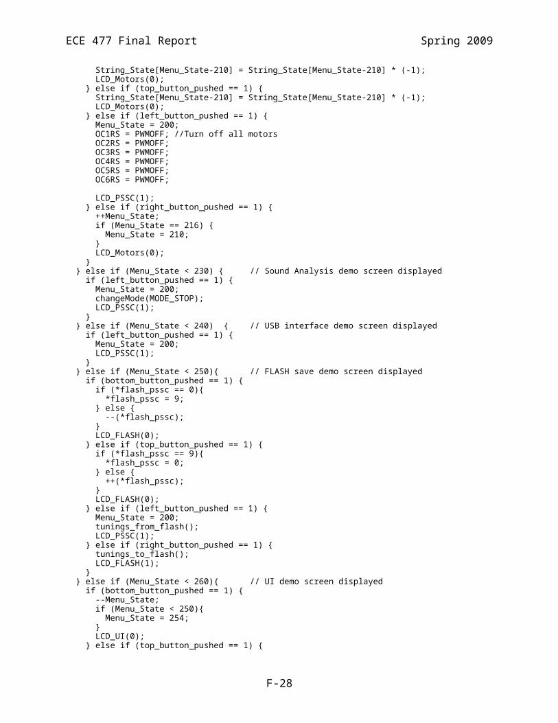
ECE 477 Final Report Spring 2009
** DSP code for ECE 477 Team 4 (das Autotunr)** Initial version: March 6, 2009* Author(s): Joe Blubaugh******/
#include "p33FJ64GP306.h" //Our PCB
#include "dsp.h"#include "ADCroutines.h"#include "peakDetection.h"#include "delay.h"#include "libq.h"#include <stdlib.h>
/* Some of these macros are taken from Microchip example code for dsPIC33F devices. Also, many device initialization lines are taken directly from Microchip example code */
// Internal FRC Oscillator_FGS(GWRP_OFF);_FOSCSEL(FNOSC_FRCPLL);_FOSC(FCKSM_CSECMD & OSCIOFNC_ON & POSCMD_XT);_FWDT(FWDTEN_OFF);
//Global ADC arraysvolatile fractional ADCWindow[ADC_WINDOW_SIZE] __attribute__ ((space(xmemory), far));volatile fractional ADCAverageAmplitude __attribute__ ((space(xmemory), far));volatile fractcomplex ADCSampleVector[ADC_VECTOR_SIZE] __attribute__ ((space(ymemory), far, aligned(ADC_VECTOR_SIZE)));volatile fractcomplex FFTResultVector[ADC_VECTOR_SIZE] __attribute__ ((space(ymemory), far, aligned(ADC_VECTOR_SIZE)));volatile fractional FFTMagnitudeVector[ADC_VECTOR_SIZE] __attribute__ ((space(xmemory), far, aligned(ADC_VECTOR_SIZE)));volatile fractional FFTAverageFilter[ADC_AVG_FILTER_SIZE] __attribute__ ((space(xmemory), far));volatile fractional FFTAverageOutput[ADC_VECTOR_SIZE+ADC_AVG_FILTER_SIZE+1] __attribute__((space(xmemory), far));volatile unsigned int ADCMode __attribute__((space(xmemory)));volatile unsigned int ADCState __attribute__((space(xmemory)));volatile fractional ADCInstVal __attribute__((space(xmemory)));volatile fractional ADCBgNoise __attribute__((space(xmemory)));volatile fractional ADCDownsampleAvg __attribute__((space(xmemory)));fractcomplex twiddles[ADC_VECTOR_SIZE/2] __attribute__((space(xmemory), far, aligned (ADC_VECTOR_SIZE*2)));volatile notePack NoteHistory[NUM_NOTES] __attribute__((space(xmemory), far));volatile unsigned int NotesFound __attribute__((far));volatile unsigned int NoteSent __attribute__((far)); //Set by SPI when it finishes sending a packet//Fractional debug varsvolatile fractional a __attribute__((space(xmemory)));volatile fractional b __attribute__((space(xmemory)));volatile fractional c[2] __attribute__((space(xmemory)));
extern volatile char midi_note_found;
//LCD Textconst char mytext[] __attribute__((space(xmemory))) = " Joe's ADC Test ";const char mytext1[] __attribute__((space(xmemory))) = " S4 starts ADC ";const char mytext2[] __attribute__((space(xmemory))) = " S3 starts samp ";const char sampText[] __attribute__((space(xmemory))) =" Sampling... ";
F-56

ECE 477 Final Report Spring 2009
const char doneText[] __attribute__((space(xmemory))) =" Sampling done ";const char FFTtext[] __attribute__((space(xmemory))) = " Doing FFT... ";volatile int message;
int main (void){
unsigned int i, j; int index; volatile fractional maxi, mini, scaleFact; //remove volatile to improve performance after debug
/* First, set up the oscilator * Fosc = Fin*M/(N1*N2), Fcy = Fosc / 2 * Fosc = 7.37M * 41/(2*2) = 7.92Mhz for 7.37 input clock */
initOSC();
ADCMode = ADC_NEUTRAL_MODE; //sample at 1/4 freqADCState = ADC_STARTUP_STATE; //Watch and average input
//Init Modules, define interrupts, all of that.for (i=0;i<ADC_WINDOW_SIZE;i++) {
ADCWindow[i] = 0;}//init filterfor (i=0;i<ADC_AVG_FILTER_SIZE;i++) {
FFTAverageFilter[i] = ADC_ONE_OVER_FILTER_LEN;}
spi1_init(); initTimer(); initADC(); //Init_LCD(); NotesFound = 0; NoteSent = 0; for (i=0;i<NUM_NOTES;i++) { NoteHistory[i][0][0] = 0xFFFF; NoteHistory[i][0][1] = 0; NoteHistory[i][1][0] = 0; NoteHistory[i][1][1] = 0; NoteHistory[i][2][0] = 0; NoteHistory[i][2][1] = 0; NoteHistory[i][3][0] = 0; NoteHistory[i][3][1] = 0; NoteHistory[i][4][0] = 0; NoteHistory[i][4][1] = 0; NoteHistory[i][5][0] = 0; NoteHistory[i][5][1] = 0; NoteHistory[i][6][0] = 0; NoteHistory[i][6][1] = 0; NoteHistory[i][7][0] = 0x7777; NoteHistory[i][7][1] = 0; }
//Init ADC sample vector to include zerosfor (i=ADC_NUM_SAMPLES;i<ADC_VECTOR_SIZE;i++) {
ADCSampleVector[i].real &= 0x0000;ADCSampleVector[i].imag &= 0x0000;
}//Init Twiddle Factors with no conj flag (forward DFT)TwidFactorInit(ADC_VECTOR_SIZE_LOG2, twiddles, 0);while (ADCState == ADC_STARTUP_STATE) {};
if (SPI1STATbits.SPIRBF == 1) {
F-57

ECE 477 Final Report Spring 2009
message = SPI1BUF; }
i = 0; while (1) {
i++; if (ADCMode == ADC_TUNING_MODE) {
asm volatile("nop");//Check for message from PICif (PORTDbits.RD0 == 1) {
//Initialize an SPI read SPI1BUF = 0; message = 0; //while(message != 100000) { message++;} while(SPI1STATbits.SPITBF == 1){ asm volatile("nop");} while(SPI1STATbits.SPIRBF != 1){ asm volatile("nop");}
message = SPI1BUF;ADCChangeMode(message);continue;
}
//Should we start sampling?if ((ADCAverageAmplitude > ADC_SAMPLE_THRESH)
&& (ADCState == ADC_MONITOR_STATE)) {ADCState = ADC_SAMPLE_STATE_PICK;
}
if ((ADCState == ADC_SAMPLE_STATE) &&(ADCAverageAmplitude < ADC_SAMPLE_THRESH)) { ADCState = ADC_MONITOR_STATE;
}
if (ADCState == ADC_FINISHED_STATE) { //Check for message from PIC
if (PORTDbits.RD0 == 1) {//Initialize an SPI read
SPI1BUF = 0; while(SPI1STATbits.SPITBF == 1){ asm("nop"); } while(SPI1STATbits.SPIRBF != 1){ asm("nop"); } message = SPI1BUF;
ADCChangeMode(message); continue; //Don't send, if we get a mode change
} //Send out one note packet
for (j=0;j<SPI_PKT_SIZE;j++) { SPI1BUF = (NoteHistory[NotesFound - 1][j][0]); //Send note index while(SPI1STATbits.SPITBF == 1){}
while(SPI1STATbits.SPIRBF != 1){} message = SPI1BUF;
}
asm volatile("nop"); NoteSent = 1;
ADCState = ADC_SAMPLE_STATE;}
if (NotesFound == NUM_NOTES) { NotesFound = 0; for (i=0;i<NUM_NOTES;i++) { NoteHistory[i][0][0] = 0xFFFF;
NoteHistory[i][0][1] = 0;
F-58

ECE 477 Final Report Spring 2009
NoteHistory[i][1][0] = 0; NoteHistory[i][1][1] = 0; NoteHistory[i][2][0] = 0;
NoteHistory[i][2][1] = 0; NoteHistory[i][3][0] = 0; NoteHistory[i][3][1] = 0; NoteHistory[i][4][0] = 0;
NoteHistory[i][4][1] = 0; NoteHistory[i][5][0] = 0; NoteHistory[i][5][1] = 0; NoteHistory[i][6][0] = 0;
NoteHistory[i][6][1] = 0; NoteHistory[i][7][0] = 0x7777; NoteHistory[i][7][1] = 0;
}}
if (ADCState == ADC_FFT_READY_STATE) { //Not Sampling//Do FFTasm volatile("nop");
if (NotesFound == 5) {asm volatile("nop");
} maxi = VectorMax(ADC_VECTOR_SIZE*2, ADCSampleVector, &i);
mini = _Q15abs(VectorMin(ADC_VECTOR_SIZE*2, ADCSampleVector, &i)); scaleFact = __builtin_divf(HALF, MAX(maxi, mini));
VectorScale(ADC_VECTOR_SIZE*2, //fractional, 2 ints per element ADCSampleVector, ADCSampleVector, scaleFact);
FFTComplex(ADC_VECTOR_SIZE_LOG2, FFTResultVector, ADCSampleVector, twiddles, COEFFS_IN_DATA);
//Amplify here? Needed if not enough resolution in magnitudeSquareMagnitudeCplx(ADC_VECTOR_SIZE, FFTResultVector, FFTMagnitudeVector);//Amplify here? Simple, just a shift since all values are positiveasm volatile("nop");autoAmplifyUFractVector(ADC_VECTOR_SIZE, FFTMagnitudeVector, FFTMagnitudeVector);
//Filter with 16-tap averageVectorConvolve(ADC_VECTOR_SIZE, ADC_AVG_FILTER_SIZE, FFTAverageOutput, FFTMagnitudeVector, FFTAverageFilter);//ID max frequency//peakDetect(TUNING_MAX_FREQ, 2, FFTAverageOutput, //&(NoteHistory[NotesFound][1]));
if (NotesFound == 3) {asm volatile("nop");
}dataDrivenPeakDetect(TUNING_MAX_FREQ, &(FFTAverageOutput[7]), &(NoteHistory[NotesFound][1]));
//NoteHistory[NotesFound][1][0] = index; NotesFound++; asm volatile("nop");
ADCState = ADC_FINISHED_STATE;
}} //Tuning Mode
if (ADCMode == ADC_MIDI_MODE) {if (PORTDbits.RD0 == 1) {
//Initialize an SPI read SPI1BUF = 0; message = 0; //while(message != 100000) { message++;} while(SPI1STATbits.SPITBF == 1){ asm("nop"); } while(SPI1STATbits.SPIRBF != 1){ asm("nop"); }
F-59

ECE 477 Final Report Spring 2009
message = SPI1BUF; asm volatile("nop");
ADCChangeMode(message);continue;
}
if ((ADCAverageAmplitude > ADC_SAMPLE_THRESH) && (ADCState == ADC_MONITOR_STATE)) {
//Update LCD messageADCState = ADC_SAMPLE_STATE_PICK;
}
if ((ADCState == ADC_SAMPLE_STATE) &&(ADCAverageAmplitude < ADC_SAMPLE_THRESH)) { ADCState = ADC_MONITOR_STATE;
}
if (ADCState == ADC_FFT_READY_STATE) {//Peak Detectmaxi = VectorMax(ADC_VECTOR_SIZE*2, ADCSampleVector, &i);
mini = _Q15abs(VectorMin(ADC_VECTOR_SIZE*2, ADCSampleVector, &i)); scaleFact = __builtin_divf(HALF, MAX(maxi, mini));
VectorScale(ADC_VECTOR_SIZE*2, //fractional, 2 ints per element ADCSampleVector, ADCSampleVector, scaleFact);
FFTComplex(ADC_VECTOR_SIZE_LOG2, FFTResultVector, ADCSampleVector, twiddles, COEFFS_IN_DATA);
//Amplify here? Needed if not enough resolution in magnitudeSquareMagnitudeCplx(ADC_VECTOR_SIZE, FFTResultVector, FFTMagnitudeVector);autoAmplifyUFractVector(ADC_VECTOR_SIZE, FFTMagnitudeVector, FFTMagnitudeVector);VectorConvolve(ADC_VECTOR_SIZE, ADC_AVG_FILTER_SIZE, FFTAverageOutput, FFTMagnitudeVector, FFTAverageFilter);//Detect a single peak, send it outpeakDetect(MIDI_MAX_FREQ, 1, FFTAverageOutput, &(NoteHistory[0][1]));
ADCState = ADC_SAMPLE_STATE;
midi_note_found = 1;}
}
if (ADCMode == ADC_NEUTRAL_MODE) {if (PORTDbits.RD0 == 1) {
//Initialize an SPI read SPI1BUF = 0; message = 0; //while(message != 100000) { message++;} while(SPI1STATbits.SPITBF == 1){ asm volatile("nop");} while(SPI1STATbits.SPIRBF != 1){ asm volatile("nop");}
message = SPI1BUF; asm volatile("nop");
ADCChangeMode(message);}
}}; //while(1)
}
ADCroutines.c/******* DSP code for ECE 477 Team 4 (das Autotunr)** Initial version: March 6, 2009
F-60

ECE 477 Final Report Spring 2009
* Author(s): Joe Blubaugh******/
#include "p33FJ64GP306.h" //Our PCB#include "dsp.h"#include "ADCroutines.h"#include "libq.h"
extern volatile fractional ADCWindow[ADC_WINDOW_SIZE] __attribute__ ((space(xmemory)));extern volatile fractional ADCAverageAmplitude __attribute__ ((space(xmemory)));extern volatile fractcomplex ADCSampleVector[ADC_VECTOR_SIZE] __attribute__ ((space(ymemory), far));extern volatile fractcomplex FFTResultVector[ADC_VECTOR_SIZE] __attribute__ ((space(ymemory), far));extern volatile fractional FFTMagnitudeVector[ADC_VECTOR_SIZE] __attribute__ ((space(xmemory)));extern volatile unsigned int ADCMode __attribute__((space(xmemory)));extern volatile unsigned int ADCState __attribute__((space(xmemory)));extern volatile fractional ADCInstVal __attribute__((space(xmemory)));extern volatile fractional ADCBgNoise __attribute__((space(xmemory)));extern volatile fractional ADCDownsampleAvg __attribute__((space(xmemory)));extern volatile unsigned int NotesFound __attribute__((far));extern volatile notePack NoteHistory[NUM_NOTES] __attribute__((space(xmemory), far));
volatile char midi_note_found;
void ADCChangeMode(int message) {ADCState = ADC_MONITOR_STATE;
int i, j;
switch (message) {case MODE_STOP:
ADCMode = ADC_NEUTRAL_MODE;break;
case MIDI_START:ADCMode = ADC_MIDI_MODE;break;
case TUNING_START:ADCMode = ADC_TUNING_MODE;break;
default:while (1) {
asm volatile("nop");} //break here
}//Delay here
Delay_Us(MODE_CHANGE_DELAY);NotesFound = 0;
}
void spi1_init(void) { IFS0bits.SPI1IF = 0; //Clear the Interrupt Flag IEC0bits.SPI1IE = 0; //disable the Interrupt // SPI1CON1 Register Settings SPI1CON1bits.DISSCK = 0; //Internal Serial Clock is Enabled. SPI1CON1bits.DISSDO = 0; //SDOx pin is controlled by the module. SPI1CON1bits.MODE16 = 1; //Communication is word-wide (16 bits). SPI1CON1bits.SMP = 0; //Input Data is sampled at the middle of data output time. SPI1CON1bits.CKE = 0; //Serial output data changes on transition from //Idle clock state to active clock state SPI1CON1bits.CKP = 0; //Idle state for clock is a low level;
F-61

ECE 477 Final Report Spring 2009
//active state is a high level SPI1CON1bits.MSTEN = 1; //Master Mode Enabled SPI1STATbits.SPIEN = 1; //Enable SPI Module SPI1BUF = 0x0000; //Write data to be transmitted //Interrupt Controller Settings IFS0bits.SPI1IF = 0; //Clear the Interrupt Flag IEC0bits.SPI1IE = 0; //Enable the Interrupt}
void initADC(void) {midi_note_found = 0;
//Set ports to analog input AD1PCFGLbits.PCFG4 = 0; //Port 4 is audio input TRISBbits.TRISB4 = 1; //Port 4 is also RB4//Debugging port pin set up;AD1PCFGLbits.PCFG10 = 1;TRISBbits.TRISB10 = 0;PORTBbits.RB10 = 0;AD1PCFGLbits.PCFG11 = 1;TRISBbits.TRISB11 = 0;PORTBbits.RB11 = 0;AD1PCFGLbits.PCFG12 = 1;TRISBbits.TRISB12 = 0;PORTBbits.RB12 = 0;AD1PCFGLbits.PCFG13 = 1;TRISBbits.TRISB13 = 0;PORTBbits.RB13 = 0;
AD1CON1bits.AD12B = 1; //12 bit operationAD1CON1bits.ADSIDL = 0; //Do not run in Idle modeAD1CON1bits.ADDMABM = 0; //DMA write in order in buffer ADBUF0
//Auto sample, timer convertAD1CON1bits.ASAM = 1;AD1CON1bits.SSRC0 = 0;AD1CON1bits.SSRC1 = 1;AD1CON1bits.SSRC2 = 0;
//Signed fractional outputAD1CON1bits.FORM = 0b11;
//No channel scan, use MuxA, Interrupts on every sampleAD1CON2 = 0x0000;
//Set Clock rate. TAD = (AD1CON3<7:0> + 1) * TCY //For TCY = 1/(40 MHz) = 25 ns, set TAD = 80 * TCY = 2 us AD1CON3 = 0x032F; //Channel select AN4 AD1CHS0 = ADC_MICROPHONE; //Reset ADC interrupt flag IFS0bits.AD1IF = 0; //Enable ADC interrupts IEC0bits.AD1IE = 1; //Enable ADC AD1CON1bits.ADON = 1;}
void initTimer(void) {//Initialize timer 3,2 to get an ADC sample rate of 700 Hz
//Reset T3, T2T3CON = 0;
F-62

ECE 477 Final Report Spring 2009
T2CON = 0;T4CON = 0;
T3CONbits.TSIDL = 0;T4CONbits.TSIDL = 0;
//Clock prescale to 1T2CONbits.TCKPS = ADC_TIMER2_PRESCALE;T4CONbits.TCKPS = ADC_TIMER4_PRESCALE;
TMR3 = 0x00;TMR2 = 0x00;TMR4 = 0x00;
//Concatenate T3:T2T2CONbits.T32 = 1;PR3 = ADC_TIMER3_PERIOD;PR2 = ADC_TIMER2_PERIOD;PR4 = ADC_TIMER4_PERIOD;
//Clear interrupt flag and enable interruptsIPC2bits.T3IP = 4;IFS0bits.T3IF = 0;IEC0bits.T3IE = 1;
IPC6bits.T4IP = 4;IFS1bits.T4IF = 0;IEC1bits.T4IE = 1;
//Turn on T2T2CONbits.TON = 1;T4CONbits.TON = 1;
}
void __attribute__((interrupt, shadow, auto_psv)) _ADC1Interrupt(void) {static int i = 0;static int j = 1;static int L = 0;int k;
static int pickCount = 0; static int divCount = 1;
//Clear interrupt flagIFS0bits.AD1IF = 0;
//Toggle debuggin' line PORTBbits.RB10 = LATBbits.LATB10 ^ 1; if (divCount == ADC_TUNING_DIVIDE) {
PORTBbits.RB11 = LATBbits.LATB11 ^ 1;divCount = 0;
}divCount++;
//Take value from buffer, put in sample array. ADCWindow[i] = ADC1BUF0;
ADCInstVal = ADC1BUF0;i++;i %= ADC_WINDOW_SIZE;
//Put samples in the ADC Sample buffer only when we're in sample mode.//Quit after 1 set of sampling.
if (ADCState == ADC_STARTUP_STATE) {
F-63

ECE 477 Final Report Spring 2009
//On startup, take a background average measurement//We'll use this to compute a threshold for 'loud enough'
if (j == ADC_STARTUP_DIVIDE) {ADCSampleVector[L].real = ADC1BUF0;L++;j = 0;
}j++;if (L >= ADC_WINDOW_SIZE) {
ADCBgNoise = 0;for (k=0;k < ADC_WINDOW_SIZE;k++) {
ADCBgNoise += ADCSampleVector[k].real;}ADCBgNoise /= ADC_WINDOW_SIZE;L = 0;ADCState = ADC_MONITOR_STATE;j = 0;
}}
else if (ADCState == ADC_SAMPLE_STATE_PICK) { L++; if (L == ADC_PICK_DISCARD) { ADCState = ADC_SAMPLE_STATE; L = 0; pickCount = 0; } }
else if (ADCState == ADC_SAMPLE_STATE) {if (ADCMode == ADC_TUNING_MODE) {
if (j == ADC_TUNING_DIVIDE) {//Put divide average values in ADC samp vectorADCDownsampleAvg &= 0x0000;for (k=i;k>i-ADC_TUNING_DIVIDE;k--) {
//This is problematic: could shift all the data out//Also, I don't think this preserves sign.ADCDownsampleAvg += ADCWindow[(k < 0 ? ADC_WINDOW_SIZE + k : k)] >>
ADC_TUNING_DIVIDE_LOG2; }ADCSampleVector[L].real = ADCInstVal;L++;j = 0;
}j++;
} else if (ADCMode == ADC_MIDI_MODE) {if (j == ADC_MIDI_DIVIDE) {
//Put divide average values in ADC samp vectorADCDownsampleAvg &= 0x0000;for (k=i;k>i-ADC_TUNING_DIVIDE;k--) {
ADCDownsampleAvg += ADCWindow[(k < 0 ? ADC_WINDOW_SIZE + k : k)] >> ADC_MIDI_DIVIDE_LOG2;
}ADCSampleVector[L].real = ADCInstVal;L++;j = 0;
}j++;
}if (L >= ADC_NUM_SAMPLES){
ADCState = ADC_FFT_READY_STATE;}
} else {L = 0;
F-64

ECE 477 Final Report Spring 2009
}ADCAverageAmplitude = 0;for (k=0;k<ADC_WINDOW_SIZE;k++) {
ADCAverageAmplitude += _Q15abs(ADCWindow[k]) >> ADC_WINDOW_SIZE_LOG2;}
}
void __attribute__((interrupt, shadow, auto_psv)) _T4Interrupt(void) { //For sending MIDI packets.
int j, message; PORTBbits.RB12 = LATBbits.LATB12 ^ 1;
IFS1bits.T4IF = 0;PR4 = ADC_TIMER4_PERIOD;if (ADCMode == ADC_MIDI_MODE) {
if (midi_note_found == 1) {//Check for message from PICif (PORTDbits.RD0 == 1) {
//Initialize an SPI read SPI1BUF = 0; while(SPI1STATbits.SPITBF == 1){asm("nop");}
while(SPI1STATbits.SPIRBF != 1){asm("nop");} message = SPI1BUF;
ADCChangeMode(message);return;
}for (j=0;j<SPI_PKT_SIZE;j++) {
SPI1BUF = (NoteHistory[0][j][0]); //Send note index, not derivative while(SPI1STATbits.SPITBF == 1){asm("nop");}
while(SPI1STATbits.SPIRBF != 1){asm("nop");}message = SPI1BUF;
}message = SPI1BUF;midi_note_found = 0;
}else {
//Check for message from PICif (PORTDbits.RD0 == 1) {
//Initialize an SPI read SPI1BUF = 0; while(SPI1STATbits.SPITBF == 1){asm("nop");}
while(SPI1STATbits.SPIRBF != 1){asm("nop");}message = SPI1BUF;ADCChangeMode(message);return;
}//End of Packet...SPI1BUF = SPI_START_PKT;while(SPI1STATbits.SPITBF == 1){asm("nop");}while(SPI1STATbits.SPIRBF != 1){asm("nop");}message = SPI1BUF;SPI1BUF = SPI_START_PKT;while(SPI1STATbits.SPITBF == 1){asm("nop");}while(SPI1STATbits.SPIRBF != 1){asm("nop");}message = SPI1BUF;SPI1BUF = SPI_START_PKT;while(SPI1STATbits.SPITBF == 1){asm("nop");}while(SPI1STATbits.SPIRBF != 1){asm("nop");}message = SPI1BUF;SPI1BUF = SPI_START_PKT;while(SPI1STATbits.SPITBF == 1){asm("nop");}while(SPI1STATbits.SPIRBF != 1){asm("nop");}message = SPI1BUF;
F-65

ECE 477 Final Report Spring 2009
SPI1BUF = SPI_START_PKT;while(SPI1STATbits.SPITBF == 1){asm("nop");}while(SPI1STATbits.SPIRBF != 1){asm("nop");}message = SPI1BUF;SPI1BUF = SPI_START_PKT;while(SPI1STATbits.SPITBF == 1){asm("nop");}while(SPI1STATbits.SPIRBF != 1){asm("nop");}message = SPI1BUF;SPI1BUF = SPI_START_PKT;while(SPI1STATbits.SPITBF == 1){asm("nop");}while(SPI1STATbits.SPIRBF != 1){asm("nop");}message = SPI1BUF;SPI1BUF = SPI_END_PKT;while(SPI1STATbits.SPITBF == 1){asm("nop");}while(SPI1STATbits.SPIRBF != 1){asm("nop");}message = SPI1BUF;
}}
}
void __attribute__((interrupt, shadow, auto_psv)) _T3Interrupt(void) {//Clear interrupt flagIFS0bits.T3IF = 0;
//Reset PER registerPR3 = ADC_TIMER3_PERIOD;PR2 = ADC_TIMER2_PERIOD;
// PORTAbits.RA2 ^= 1;}
void initOSC() { PLLFBD = 148; CLKDIVbits.PLLPOST = 0; CLKDIVbits.PLLPRE = 5; OSCCONbits.NOSC = 1; //FRC w/ PLL OSCCONbits.OSWEN = 1; //Perform a clock switch while (OSCCONbits.OSWEN != 0) {}; //wait for clock switch while (OSCCONbits.LOCK == 0) {}; //wait for PLL lock}
peakDetection.c#include "p33FJ64GP306.h"#include "dsp.h"#include "ADCroutines.h"#include "libq.h"#include "peakDetection.h"
void dataDrivenPeakDetect( int vectorSize, fractional *srcV, notePack *note) {
int Epeaks[4] = {82, 161, 248, 330}; //3 peaks int Fpeaks[4] = {87, 174, 261, 348}; int Fspeaks[4] = {93, 185, 281, 373}; int Gpeaks[4] = {98, 196, 294, 392}; int Gspeaks[3] = {104, 208, 312}; int Apeaks[3] = {110, 220, 330}; int Aspeaks[3] = {117, 233, 350}; int Bpeaks[2] = {123, 247}; int Cpeaks[5] = {65, 129, 196, 262, 307}; int Cspeaks[5] = {69, 139, 208, 277, 347}; int Dpeaks[4] = {73, 147, 220, 293}; int Dspeaks[4] = {78, 156, 233, 311};
F-66
ECE 477 Final Report Spring 2009
int testPeaks[6][4]; fractional peaks[4]; int width; int mIndex, i; meritPack merits[12];
calcMerit(Epeaks, 4, vectorSize, srcV, &merits[0]); calcMerit(Fpeaks, 4, vectorSize, srcV, &merits[1]); calcMerit(Fspeaks, 4, vectorSize, srcV, &merits[2]); calcMerit(Gpeaks, 4, vectorSize, srcV, &merits[3]); calcMerit(Gspeaks, 3, vectorSize, srcV, &merits[4]); calcMerit(Apeaks, 3, vectorSize, srcV, &merits[5]); calcMerit(Aspeaks, 3, vectorSize, srcV, &merits[6]); calcMerit(Bpeaks, 2, vectorSize, srcV, &merits[7]); calcMerit(Cpeaks, 5, vectorSize, srcV, &merits[8]); calcMerit(Cspeaks, 5, vectorSize, srcV, &merits[9]); calcMerit(Dpeaks, 4, vectorSize, srcV, &merits[10]);
calcMerit(Dspeaks, 4, vectorSize, srcV, &merits[11]);
mIndex = 0;for (i=0;i<12;i++) {
if (merits[i][0] > merits[mIndex][0]) {mIndex = i;
}}//This will need to get more complicated: divisions for certain notes, etc.(*(note))[0][0] = merits[mIndex][1];
}
void calcMerit( int *peaksArray, int numPeaks, int vectorSize, fractional *srcV, meritPack* merit) {
int i, width, maxind;int strength[5], indexes[5];int ampler = 4;
merit[0][0] = 0;for (i=0;i<numPeaks;i++) {
//set ampler based on freq? not sure yet...width = peaksArray[i] >> 4;strength[i] = VectorMax(width << 1, &(srcV[peaksArray[i] - width]),
&(indexes[i])); indexes[i] += peaksArray[i] - width;
merit[0][0] += strength[i] - ( abs(peaksArray[i] - indexes[i]) << ampler );}
merit[0][0] = merit[0][0] / numPeaks;
//choose index of strongest strengthmaxind = 0;for (i=0;i<numPeaks;i++) {
if (strength[i] > strength[maxind]) {maxind = i;
}}merit[0][1] = indexes[maxind];
}
void autoAmplifyUFractVector( int vectorSize, fractional* outputVector, fractional* inputVector) { fractional max; unsigned int i;
max = VectorMax(vectorSize, inputVector, &i);
F-67

ECE 477 Final Report Spring 2009
//Find highest bit in max i = 0; while ((max & 0x2000) == 0) {
i++; max = max << 1; if (i > 10) { i = 10; break; } }
AmplifyUFractVector( vectorSize, i, outputVector, inputVector ); return;}
void AmplifyUFractVector( int vectorSize, int poweroftwo, fractional* outputVector, fractional* inputVector) { //In-place capable of amplifying fractional vectors by a power of 2 //Incredibly unprotected, does no bounds-checking, overflow checking, anything. //Really, just left shifts an entire vector by a value unsigned int i;
for (i=0;i<vectorSize;i++) { outputVector[i] = inputVector[i] << poweroftwo; }}
void partitionedPeakDetect( int vectorSize, fractional* srcV, notePack* note) { int lowerBounds[6] = {65 << 1, 87 << 1, 116, 147, 196, 262}; int upperBounds[6] = {93 << 1, 122 << 1, 165, 220, 277, 370}; fractional averageSamples[16]; volatile fractional average; int sampleInterval; int vectorLength; int lbound, ubound, index; int lp1; int lp2; fractional pMaxi;
for (lp1=0;lp1<6;lp1++) { //One for each note vectorLength = upperBounds[lp1] - lowerBounds[lp1]; pMaxi = VectorMax(vectorLength, &(srcV[(lowerBounds[lp1])]), &index);
//Compute (approximate) vector average //Sample 16 members of the index sampleInterval = vectorLength >> 4; for (lp2=0;lp2<16;lp2++) { averageSamples[lp2] = srcV[(lowerBounds[lp1] + lp2*sampleInterval)]; }
//Average two at a time so we don't lose resolution for (lp2=0;lp2<16;lp2+=2) { averageSamples[lp2] = (averageSamples[lp2] + averageSamples[lp2+1]) >> 1; } for (lp2=0;lp2<16;lp2+=4) { averageSamples[lp2] = (averageSamples[lp2] + averageSamples[lp2+2]) >> 1; } averageSamples[0] = (averageSamples[0] + averageSamples[4]) >> 1; averageSamples[8] = (averageSamples[8] + averageSamples[12]) >> 1; average = (averageSamples[0] + averageSamples[8]) >> 1;
if ( (pMaxi - average) > PEAK_THRESH ) { index += lowerBounds[lp1];
F-68

ECE 477 Final Report Spring 2009
lbound = MAX(0, index - PEAK_SQUASH_WIDTH); ubound = MIN(vectorSize -1 , index+PEAK_SQUASH_WIDTH);
if (lp1 < 2) { (*(note))[lp1][0] = index >> 1; } else { (*(note))[lp1][0] = index; } //Squash peak, squash peak*2 for (lp2=lbound; lp2<=ubound; lp2++) { srcV[lp2] = 0; //Squash peak } } else { (*(note))[lp1][0] = -1; } }}
void peakDetect( int vectorSize, int numPeaks, fractional* srcV, notePack* note) { //Make sure vectorSize is only the bottom 1/2 of the total vector int i, j, index, index_by_2; int lbound, ubound; fractional pMaxi, baseMaxi; int err15, err20, error;
for (i=0;i<numPeaks;i++) { (*(note))[i][0] = 0; }
i = 0; while (i<numPeaks) { pMaxi = VectorMax(vectorSize, srcV, &index); (*(note))[i][0] = index;
if (index > SECOND_HARM_INDEX_THRESH) { //Freq is high enough (*(note))[i][1] = 1; //Flag that harmonic detector found this.
index_by_2 = index >> 1; //Might lose some data here, oh well lbound = MAX(0, index_by_2 - BASE_FREQ_SEARCH_WIDTH); ubound = MIN(vectorSize - 1, index_by_2 + BASE_FREQ_SEARCH_WIDTH); baseMaxi = VectorMax(BASE_FREQ_SEARCH_WIDTH << 1, &(srcV[lbound]), &index_by_2); if (baseMaxi > BASE_FREQ_THRESH) {
//Squash upper frequency pMaxi = baseMaxi; index = lbound + index_by_2;
(*(note))[i][0] = index; (*(note))[i][1] = 1; //Flag that harmonic detector found this. lbound = MAX(0, index - PEAK_SQUASH_WIDTH); ubound = MIN(vectorSize -1 , index+PEAK_SQUASH_WIDTH); for (j=lbound; j<=ubound; j++) {
srcV[j] = 0; //Squash peak } } }
if (index < SUB_AUDIBLE) {
(*(note))[i][0] = 0; //Squash section lbound = MAX(0, index - PEAK_SQUASH_WIDTH); ubound = MIN(vectorSize -1 , index+PEAK_SQUASH_WIDTH); for (j=lbound; j<=ubound; j++) {
srcV[j] = 0; //Squash peak
F-69

ECE 477 Final Report Spring 2009
} continue; }
if (pMaxi < NOTE_MAG_THRESH) { asm volatile("nop"); err15 = 0; err20 = 0; for (j=0;j<i;j++) { error = abs( (*(note))[j][0] - index ); err20 += (error < 20) ? 1 : 0; err15 += (error < 15) ? 1 : 0; } if (err20 >= ERR20_THRESH || err15 >= ERR15_THRESH) { (*(note))[i][0] = 0; //Squash section lbound = MAX(0, index - PEAK_SQUASH_WIDTH); ubound = MIN(vectorSize -1 , index+PEAK_SQUASH_WIDTH); for (j=lbound; j<=ubound; j++) {
srcV[j] = 0; //Squash peak }
continue; } }
asm volatile("nop"); lbound = MAX(0, index - PEAK_SQUASH_WIDTH); ubound = MIN(vectorSize -1 , index+PEAK_SQUASH_WIDTH); if ((*(note))[i][1] == 0) { (*(note))[i][1] = pMaxi; } //In the end, this isn't going to work. Peak squash width needs to be a func of frequency, I think
asm volatile("nop"); for (j=lbound; j<=ubound; j++) {
srcV[j] = 0; //Squash peak}
//also remove 2nd harmonic index_by_2 = index << 1; lbound = MAX(0, index_by_2 - BASE_FREQ_SEARCH_WIDTH); ubound = MIN(vectorSize - 1, index_by_2 + BASE_FREQ_SEARCH_WIDTH); baseMaxi = VectorMax(BASE_FREQ_SEARCH_WIDTH << 1, &(srcV[lbound]), &index_by_2); if (baseMaxi < SECOND_HARM_MAG_THRESH) { lbound = MAX(0, index_by_2 - BASE_FREQ_SEARCH_WIDTH); ubound = MIN(vectorSize - 1, index_by_2 + BASE_FREQ_SEARCH_WIDTH); for (j=lbound; j<=ubound; j++) {
srcV[j] = 0; //Squash peak } }
(*(note))[i][0] = (*(note))[i][0] << MIDI_FREQ_SHIFT; i++; } //while (i < numPeaks) asm volatile("nop");}
fractional localDeriv( int vectorSize, int index, int width, fractional *srcV) { //Compute the local average derivative over a width. This is helpful for gauging how 'peak-like' a note is. //Width should always be a power of two and less than MAX_DERIV_WIDTH fractional derivatives[MAX_DERIV_WIDTH], avg_derivative; int i; int halfWidth;
F-70

ECE 477 Final Report Spring 2009
int widthLog2 = 0; int lbound, ubound;
avg_derivative = 0x0000; halfWidth = width >> 1;
while (((width >> widthLog2) & 0x1) == 0){ widthLog2++; }
//Need to protect against vector over/underflow lbound = MAX((index - halfWidth), 0); ubound = MIN((index + halfWidth+1), vectorSize); ubound = ubound - lbound;
for (i=0;i<ubound;i++){ derivatives[i] = srcV[index - halfWidth + i + 1] - srcV[index - halfWidth + i]; avg_derivative = _Q15add(__builtin_divf(derivatives[i], width), avg_derivative); } return avg_derivative;}
F-71

ECE 477 Final Report Spring 2009
Appendix G: FMECA Worksheet
Failure No.
Failure Mode Possible Causes Failure Effects Method of Detection
Criticality Remarks
A1 6V rail = 0V Bad connections or not connected
Absolutely nothing happens Observation Low
A2 6V rail > 6V Wall Wart fails shorted Potential damage to voltage regulators and servos
Observation High Possible injury because of overheating of components.
A3 6V rail out of tolerance Wall Wart failure Causes 5V and/or 3.3V rails to be out of tolerance (see A6, A7)
Observation Low
A4 5V rail = 0V LP4941 fails open LCD screen does not turn on, cannot connect to USB device
Observation Low Everything but the LCD screen and the USB controller should work.
A5 5V rail > 5V LP4941 fails shorted Potential damage to LCD screen and USB controller
Observation High Possible subsequent component failures.
A6 5V rail out of tolerance LP4941 failure Unpredictable operation of the LCD screen and USB controller
Observation Low
A7 3.3V rail = 0V AP1117 fails open LCD screen turns on, but no UI operation
Observation Low The LCD will display the main screen, but buttons will be nonfunctional.
A8 3.3V rail > 3.3V AP1117 fails shorted Potential damage to the PIC and dsPIC
Observation High Possible subsequent component failures.
A9 3.3V rail out of tolerance
AP1117 failure Unpredictable operation of the PIC and dsPIC
Observation Low Causes unpredictable displays on the LCD screen.
Table G-1. Power Supply Subsystem
Failure No.
Failure Mode Possible Causes Failure Effects Method of Detection
Criticality Remarks
B1 Analog line = 0V LM386 fails open, stereo jack not connected, mic. out of range
Unable to Tune guitar or Transcribe music
Observation Low
B2 Inaccurate data on analog line
LM386 failure, IC switch failure, mic. out of range
Unable to Tune guitar or Transcribe music accurately
Observation Low May be difficult to identify.
Table G-2. Audio Input Subsystem
G-1

ECE 477 Final Report Spring 2009
Failure No.
Failure Mode Possible Causes Failure Effects Method of Detection
Criticality Remarks
C1 dsPIC to PIC communication breakdown
dsPIC or PIC stuck at fault or failure
Unable to Tune guitar or Transcribe music
Incorrect signal observed on SPI line
Low User interface will still function, but no meaningful operations will be performed.
C2 PIC to USB communication breakdown
PIC stuck at fault or failure, USB controller failure
Unable to store MIDI file onto a flash drive
Incorrect signal observed on SPI line
Low User will still be able to tune their guitar.
C3 PIC to LCD communication breakdown
PIC stuck at fault or failure, LCD screen failure
Unpredictable or meaningless displays on the LCD screen
Incorrect signal observed on UART line
Low User will still be able to use the product (in theory), but would have no display to view menus.
C4 Inaccurate Tuning or Note Detection
Software error in the dsPIC or PIC
Guitar will not be tuned correctly or MIDI file will not match notes played
Observation Low May be difficult to detect.
C5 Inaccurate motor control
Software error in the PIC Motors may turn continuously Observation High Could cause strings to break if PIC continues to output the same PWM signal.
Table G-3. Microcontroller Subsystem
Failure No.
Failure Mode Possible Causes Failure Effects Method of Detection
Criticality Remarks
D1 Push button(s) signal stuck open
Button failure or debounce IC failure
User interface does not recognize the button press
Observation Low Will severely limit what the user can do based on which button(s) is(are) affected.
D2 Push button(s) signal stuck closed
Short circuit in button or debounce IC
User interface will constantly change states
Observation Low User will be unable to control the menu/product
D3 Button press counted more than once
Debounce IC failure User interface changes more than one state at a time
Observation Low User will be unable to accurately control the menu/product.
Table G-4. User Interface Subsystem
Failure No.
Failure Mode Possible Causes Failure Effects Method of Detection
Criticality Remarks
E1 Motors do not spin Motors not connected or have failed
No tuning can be done Observation Low User will still be able to transcribe.
Table G-5. Motor Subsystem
G-2