
EE 331 Design Project Final Report...
10
θωερτψυιοπασδφγηϕκλζξχϖβνμθωερτψ υιοπασδφγηϕκλζξχϖβνμθωερτψυιοπασδ φγηϕκλζξχϖβνμθωερτψυιοπασδφγηϕκλζ ξχϖβνμθωερτψυιοπασδφγηϕκλζξχϖβνμ θωερτψυιοπασδφγηϕκλζξχϖβνθωερτψ υιοπασδφγηϕκτψυιοπασδφγηϕκλζξχϖβν μθωερτψυιοπασδφγηϕκλζξχϖβνμθωερτ ψυιοπασδφγηϕκλζξχϖβνμθωερτψυιοπα σδφγηϕκλζξχϖβνμθωερτψυιοπασδφγηϕκ λζξχϖβνμθωερτψυιοπασδφγηϕκλζξχϖβ νμθωερτψυιοπασδφγηϕκλζξχϖβνμθωερτ ψυιοπασδφγηϕκλζξχϖβνμθωερτψυιοπα σδφγηϕκλζξχϖβνμθωερτψυιοπασδφγηϕκ λζξχϖβνμρτψυιοπασδφγηϕκλζξχϖβνμθ ωερτψυιοπασδφγηϕκλζξχϖβνμθωερτψυι οπασδφγηϕκλζξχϖβνμθωερτψυιοπασδφγ ηϕκλζξχϖβνμθωερτψυιοπασδφγηϕκλζξ χϖβνμθωερτψυιοπασδφγηϕκλζξχϖβνμθ ωερτψυιοπασδφγηϕκλζξχϖβνμθωερτψυι οπασδφγηϕκλζξχϖβνμθωερτψυιοπασδφγ ηϕκλζξχϖβνμθωερτψυιοπασδφγηϕκλζξ χϖβνμθωερτψυιοπασδφγηϕκλζξχϖβνμθ EE 331 – Design Project Final Report Digital Tachometer for a DC Motor Justin Schmidt, Catherine Andrews, Paul Krawczyk
Transcript of EE 331 Design Project Final Report...
θωερτψυιοπασδφγηϕκλζξχϖβνµθωερτψυιοπασδφγηϕκλζξχϖβνµθωερτψυιοπασδφγηϕκλζξχϖβνµθωερτψυιοπασδφγηϕκλζξχϖβνµθωερτψυιοπασδφγηϕκλζξχϖβνµθωερτψυιοπασδφγηϕκλζξχϖβνµθωερτψυιοπασδφγηϕκτψυιοπασδφγηϕκλζξχϖβνµθωερτψυιοπασδφγηϕκλζξχϖβνµθωερτψυιοπασδφγηϕκλζξχϖβνµθωερτψυιοπασδφγηϕκλζξχϖβνµθωερτψυιοπασδφγηϕκλζξχϖβνµθωερτψυιοπασδφγηϕκλζξχϖβνµθωερτψυιοπασδφγηϕκλζξχϖβνµθωερτψυιοπασδφγηϕκλζξχϖβνµθωερτψυιοπασδφγηϕκλζξχϖβνµθωερτψυιοπασδφγηϕκλζξχϖβνµρτψυιοπασδφγηϕκλζξχϖβνµθωερτψυιοπασδφγηϕκλζξχϖβνµθωερτψυιοπασδφγηϕκλζξχϖβνµθωερτψυιοπασδφγηϕκλζξχϖβνµθωερτψυιοπασδφγηϕκλζξχϖβνµθωερτψυιοπασδφγηϕκλζξχϖβνµθωερτψυιοπασδφγηϕκλζξχϖβνµθωερτψυιοπασδφγηϕκλζξχϖβνµθωερτψυιοπασδφγηϕκλζξχϖβνµθωερτψυιοπασδφγηϕκλζξχϖβνµθωερτψυιοπασδφγηϕκλζξχϖβνµθωερτψυιοπασδφγηϕκλζξχϖβνµθωερτψυι
EE 331 – Design Project Final Report
Digital Tachometer for a DC Motor
Justin Schmidt, Catherine Andrews, Paul Krawczyk
EE 331 Design Project Final Report Digital Tachometer for a DC Motor
By: Justin Schmidt, Catherine Andrews, Paul Krawczyk
2
Table of Contents DC Motor Tachometer Concept, Key Features and Function Specification ......................................3 Design Flow Diagram ...............................................................................................................................................4 Major Equipment List ..............................................................................................................................................5 MCU Selection..............................................................................................................................................................5 Code Block Diagrams ...............................................................................................................................................6 Hardware Block Diagrams.....................................................................................................................................7 Hardware Limitations..............................................................................................................................................9 Design Challenges and Solutions ..................................................................................................................... 10 Design Shortcomings............................................................................................................................................. 11 Design Effort and Time Expenditures............................................................................................................ 11 Appendix A – Source Code .................................................................................................................................. 12
EE 331 Design Project Final Report Digital Tachometer for a DC Motor
By: Justin Schmidt, Catherine Andrews, Paul Krawczyk
3
EE 331 Design Project Final Report
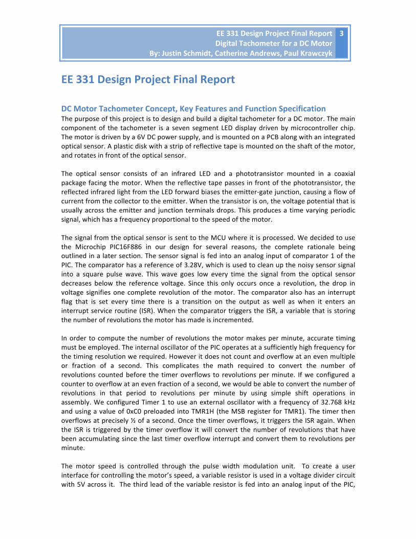
DC Motor Tachometer Concept, Key Features and Function Specification The purpose of this project is to design and build a digital tachometer for a DC motor. The main component of the tachometer is a seven segment LED display driven by microcontroller chip. The motor is driven by a 6V DC power supply, and is mounted on a PCB along with an integrated optical sensor. A plastic disk with a strip of reflective tape is mounted on the shaft of the motor, and rotates in front of the optical sensor. The optical sensor consists of an infrared LED and a phototransistor mounted in a coaxial package facing the motor. When the reflective tape passes in front of the phototransistor, the reflected infrared light from the LED forward biases the emitter-‐gate junction, causing a flow of current from the collector to the emitter. When the transistor is on, the voltage potential that is usually across the emitter and junction terminals drops. This produces a time varying periodic signal, which has a frequency proportional to the speed of the motor. The signal from the optical sensor is sent to the MCU where it is processed. We decided to use the Microchip PIC16F886 in our design for several reasons, the complete rationale being outlined in a later section. The sensor signal is fed into an analog input of comparator 1 of the PIC. The comparator has a reference of 3.28V, which is used to clean up the noisy sensor signal into a square pulse wave. This wave goes low every time the signal from the optical sensor decreases below the reference voltage. Since this only occurs once a revolution, the drop in voltage signifies one complete revolution of the motor. The comparator also has an interrupt flag that is set every time there is a transition on the output as well as when it enters an interrupt service routine (ISR). When the comparator triggers the ISR, a variable that is storing the number of revolutions the motor has made is incremented. In order to compute the number of revolutions the motor makes per minute, accurate timing must be employed. The internal oscillator of the PIC operates at a sufficiently high frequency for the timing resolution we required. However it does not count and overflow at an even multiple or fraction of a second. This complicates the math required to convert the number of revolutions counted before the timer overflows to revolutions per minute. If we configured a counter to overflow at an even fraction of a second, we would be able to convert the number of revolutions in that period to revolutions per minute by using simple shift operations in assembly. We configured Timer 1 to use an external oscillator with a frequency of 32.768 kHz and using a value of 0xC0 preloaded into TMR1H (the MSB register for TMR1). The timer then overflows at precisely ½ of a second. Once the timer overflows, it triggers the ISR again. When the ISR is triggered by the timer overflow it will convert the number of revolutions that have been accumulating since the last timer overflow interrupt and convert them to revolutions per minute. The motor speed is controlled through the pulse width modulation unit. To create a user interface for controlling the motor’s speed, a variable resistor is used in a voltage divider circuit with 5V across it. The third lead of the variable resistor is fed into an analog input of the PIC,
EE 331 Design Project Final Report Digital Tachometer for a DC Motor
By: Justin Schmidt, Catherine Andrews, Paul Krawczyk
4
which is configured to operate as the analog to digital converter input. As the resistance is changed, the voltage at the analog to digital converter input is varied, which changes the digital value of the ADC. This digital value is then sent into the pulse width register, CCP1RL. By doing this the user can control the duty cycle of the pulse causing the motor’s speed to vary. In order to let the user select between revolutions per minute and revolutions per second, a push-‐button is connected to port C. When the user presses the button, a de-‐bounce subroutine executes and waits for the user to release the button so that the PIC does not register multiple button presses. The button circuitry produces a noisy signal and the ringing may be interpreted as additional button presses by the PIC. The subroutine also continues to refresh the LED digits, switches the LED unit indicators and changes the unit variable. Another button was added to reset the MCU. The reset can be used if there is an error in the program. The reset button causes the master clear port to pulse low, which causes an asynchronous reset of the MCU. This type of reset is much more convenient than having to reset the power. The output is displayed on a four digit seven-‐segment common cathode LED display. The digit data pins of the seven-‐segment display are tied together, which causes the same number to be displayed on all digits at the same time. To get around this without using a driver, each digit has to be written to separately at different times so that different values can be outputted on the data bus. It is necessary to pulse the display for each digit separately using the address bus and a MOSFET to control the flow of current. This allows for the correct decimal value to be displayed on the correct digit. This also reduces the power consumption of the system, as current is flowing though each of the diodes only when the MOSFET is switched on from the data bus. To implement this design the display must be refreshed at a rate high enough that cannot be detected by the human eye.
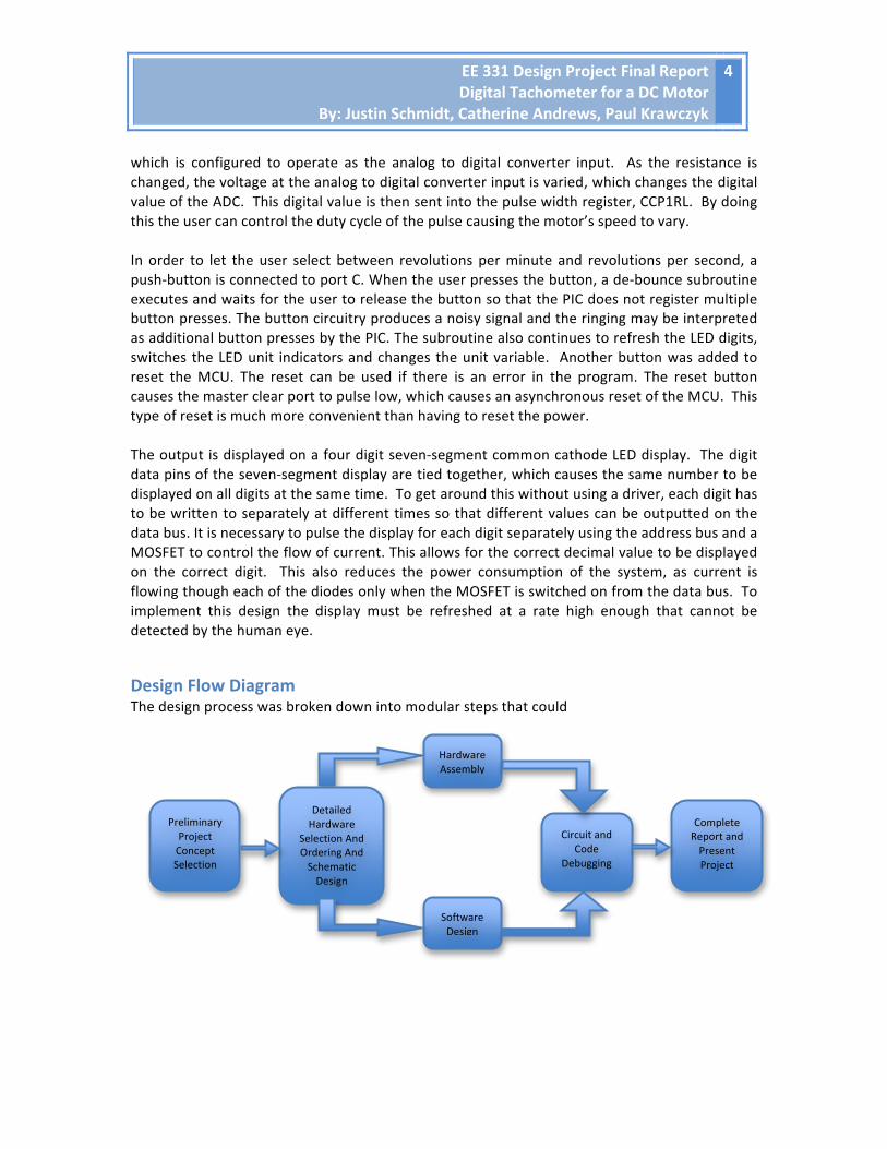
Design Flow Diagram The design process was broken down into modular steps that could
Preliminary Project Concept Selection
Hardware Assembly
Software Design
Detailed Hardware
Selection And Ordering And Schematic Design
Circuit and Code
Debugging
Complete Report and Present Project
EE 331 Design Project Final Report Digital Tachometer for a DC Motor
By: Justin Schmidt, Catherine Andrews, Paul Krawczyk
5
Major Equipment List
1. PIC16F886 2. Breadboard 3. 6V DC Brushless motor 4. Optical Sensor 5. 5V DC Voltage Regulator 6. Wiring Kit 7. PICkit 2 Programmer 8. Seven Segment Display 9. Push Button x 2 10. High Power Potentiometer 11. DC Power Supply 12. Various Resistors and Capacitors
MCU Selection Once we selected our project concept, we began to investigate the requirements that would be placed on the MCU. We selected the PIC16F886 for several reasons, some technical and others out of convenience. The 16F886 is selected because of the following criteria: Physical Packaging: The PIC16F886 is available in a dual inline package, which conveniently fits on standard breadboards. This allows us to easily modify and re-‐wire the circuit easily, and avoid having to use a printed circuit board. Availability and Familiarity: The 16F886 is used in the third year lab class (EE 391) as the MCU for one of the labs, giving us access to spares if we had a hardware failure. The 16F886 also has the same instruction set as the 16F84A, which is being covered in class. With the 886 we would not have to learn another instruction set and hardware architecture in order to properly implement the circuit. Number of I/O ports: Because the MCU would be receiving inputs from two digital buttons, and an analog voltage value from the variable resistor, we had to select a MPU with sufficient input ports. Our design required the use of seven data ports and four address ports to operate the seven-‐segment display as well as one output to control a MOSFET driving the PWM for the motor. We therefore require a total of twelve output ports. The 16F886 is on of the few midrange 16F series chips with sufficient ports for our design without going to a much more complex and expensive series of chips. Timer 1 (TMR1) Flexibility: Our design requires a timer that can be set to count and overflow at precise intervals. Since our goal is to display the motor speed in revolutions per minute and revolutions per second, we require a timer that can time intervals of precisely one second, or even fractions of a second. The PIC16F866 has the ability to be configured to count using an external oscillator. We selected a 32.768 KHz crystal, so that the 16 bit timer (loaded with H’C000’) overflows in ½ of a second. This overflow triggers an interrupt every half second, allowing us to easily convert the number of pulses from the optical sensor to RPM and RPS.
EE 331 Design Project Final Report Digital Tachometer for a DC Motor
By: Justin Schmidt, Catherine Andrews, Paul Krawczyk
6
Analog to Digital Converter (ADC): To control the speed of the motor, the PIC is required to receive an analog voltage from the voltage divider circuit. The ADC is required to convert the analog voltage level to a digital binary value, which is used to determine a corresponding pulse width value using the PWM module. Comparator: The comparator is used to clean up the input signal from the optical sensor. The optical sensor signal is compared with a reference voltage of 3.28V. The optical sensor voltage peaks at about 4.00 V. When the optical sensor voltage is lower than the reference voltage, the comparator output goes high which causes an interrupt once per motor revolution. Internal Oscillator: Having an internal oscillator eliminates the need for another second external oscillator for the PIC, freeing up ports for the I/O operations.
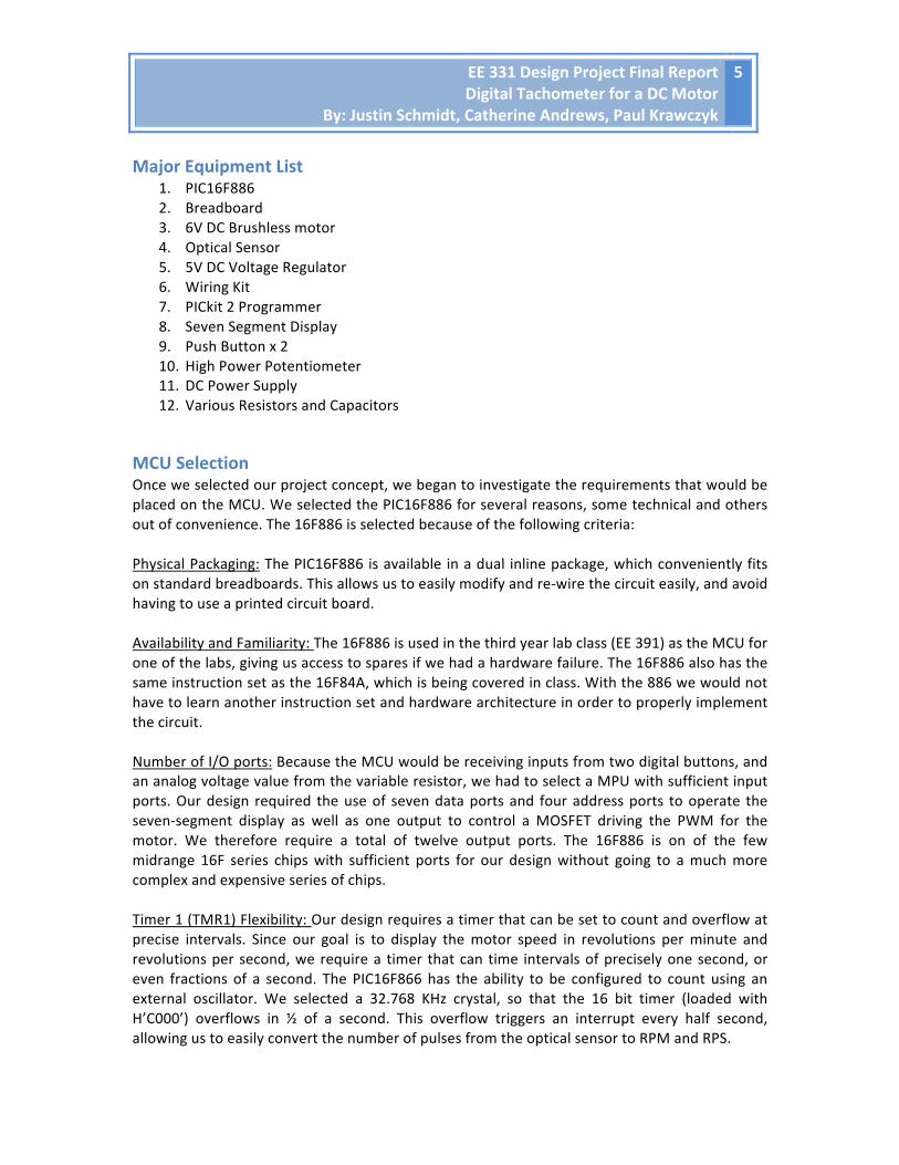
Code Block Diagrams Main Block Diagram: The main function block diagram shows the functions it is responsible for, as well as how is passes the flow of control from subroutine to subroutine.
EE 331 Design Project Final Report Digital Tachometer for a DC Motor
By: Justin Schmidt, Catherine Andrews, Paul Krawczyk
7
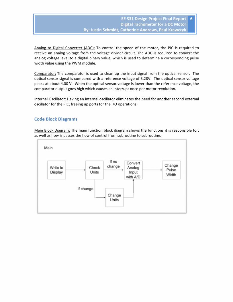
Interrupt Service Routine Block Diagram: The ISR block diagram shows how the subroutine is called, and the functions it accomplishes.
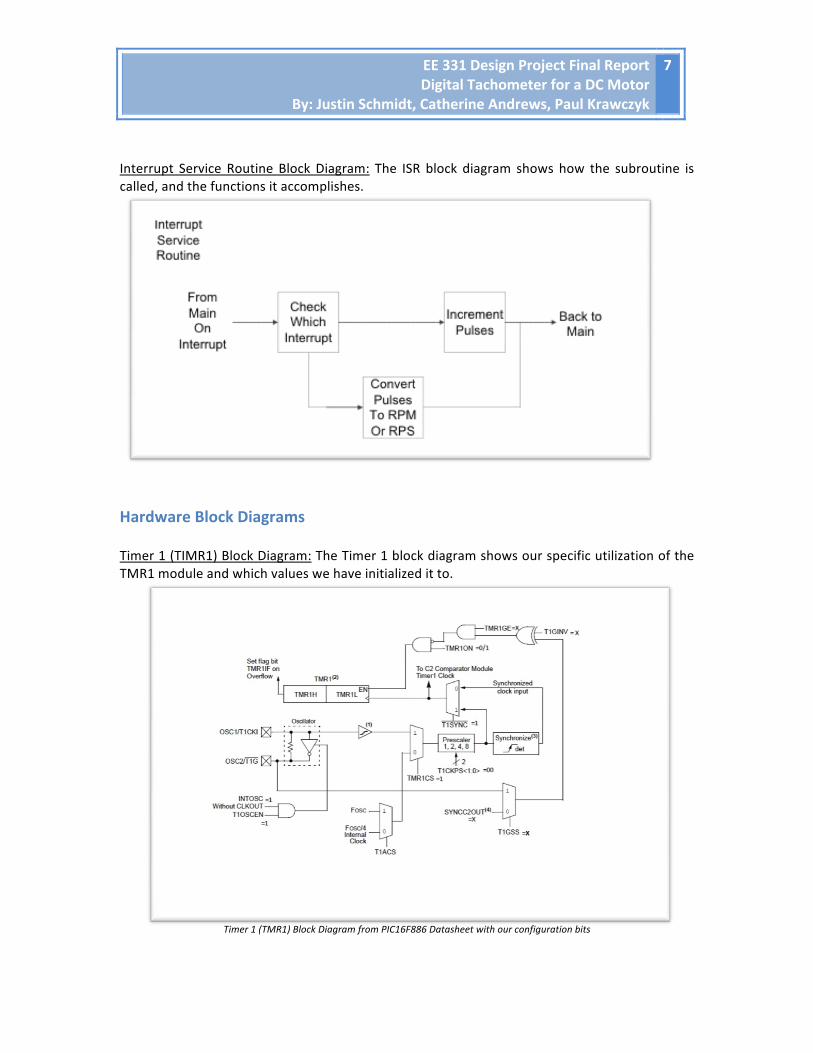
Hardware Block Diagrams Timer 1 (TIMR1) Block Diagram: The Timer 1 block diagram shows our specific utilization of the TMR1 module and which values we have initialized it to.
Timer 1 (TMR1) Block Diagram from PIC16F886 Datasheet with our configuration bits
EE 331 Design Project Final Report Digital Tachometer for a DC Motor
By: Justin Schmidt, Catherine Andrews, Paul Krawczyk
8
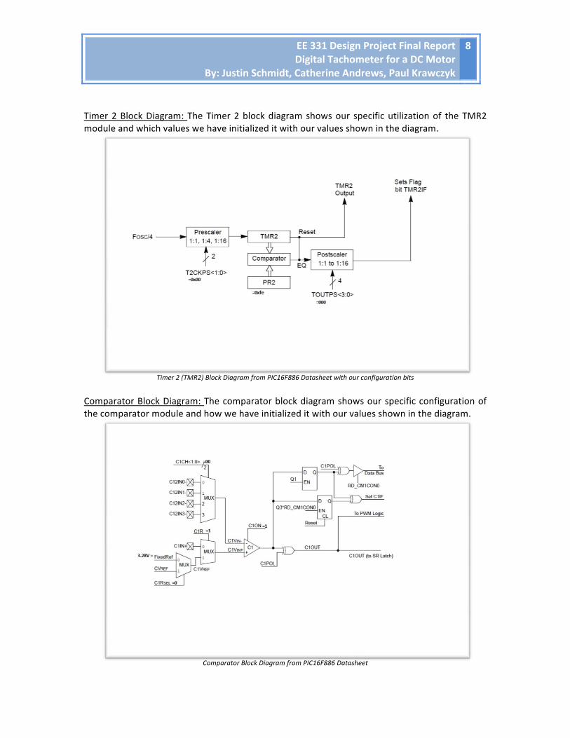
Timer 2 Block Diagram: The Timer 2 block diagram shows our specific utilization of the TMR2 module and which values we have initialized it with our values shown in the diagram.
Timer 2 (TMR2) Block Diagram from PIC16F886 Datasheet with our configuration bits
Comparator Block Diagram: The comparator block diagram shows our specific configuration of the comparator module and how we have initialized it with our values shown in the diagram.
Comparator Block Diagram from PIC16F886 Datasheet
EE 331 Design Project Final Report Digital Tachometer for a DC Motor
By: Justin Schmidt, Catherine Andrews, Paul Krawczyk
9
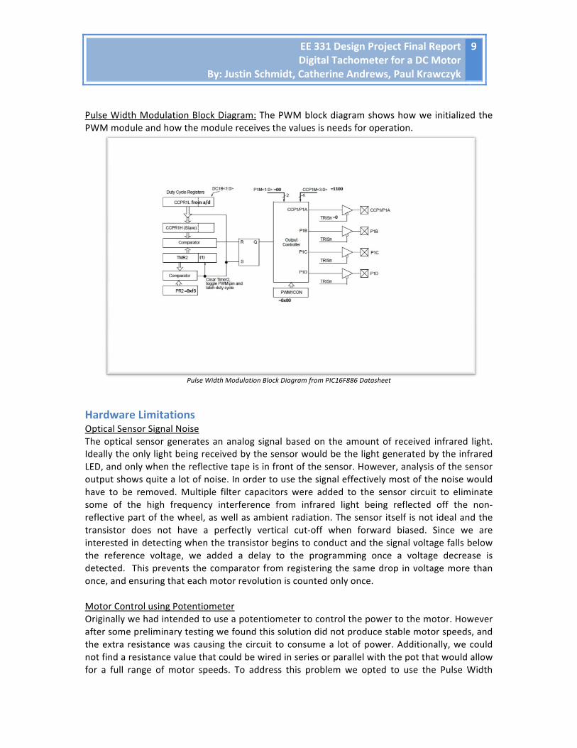
Pulse Width Modulation Block Diagram: The PWM block diagram shows how we initialized the PWM module and how the module receives the values is needs for operation.
Pulse Width Modulation Block Diagram from PIC16F886 Datasheet
Hardware Limitations Optical Sensor Signal Noise The optical sensor generates an analog signal based on the amount of received infrared light. Ideally the only light being received by the sensor would be the light generated by the infrared LED, and only when the reflective tape is in front of the sensor. However, analysis of the sensor output shows quite a lot of noise. In order to use the signal effectively most of the noise would have to be removed. Multiple filter capacitors were added to the sensor circuit to eliminate some of the high frequency interference from infrared light being reflected off the non-‐reflective part of the wheel, as well as ambient radiation. The sensor itself is not ideal and the transistor does not have a perfectly vertical cut-‐off when forward biased. Since we are interested in detecting when the transistor begins to conduct and the signal voltage falls below the reference voltage, we added a delay to the programming once a voltage decrease is detected. This prevents the comparator from registering the same drop in voltage more than once, and ensuring that each motor revolution is counted only once. Motor Control using Potentiometer Originally we had intended to use a potentiometer to control the power to the motor. However after some preliminary testing we found this solution did not produce stable motor speeds, and the extra resistance was causing the circuit to consume a lot of power. Additionally, we could not find a resistance value that could be wired in series or parallel with the pot that would allow for a full range of motor speeds. To address this problem we opted to use the Pulse Width

EE 331 Design Project Final Report Digital Tachometer for a DC Motor
By: Justin Schmidt, Catherine Andrews, Paul Krawczyk
10
Modulation unit on the PIC to control the duty cycle of the motor. We rewired the pot in a voltage divider circuit and connected it to pin AN9, which was configured as an analog input to the ACD. The ADC then converts the input to a number in the range of 0x00 to 0xff and passes it to CCPR1L for use in the PWM module. The PWM module then takes CCPR1L and compares it to TMR2 and sets the output high. The PR2 register sets the period for the PWM. When timer 2 reaches the value of PR2 the output and the timer is reset.
Design Challenges and Solutions There were numerous design challenges that our group faced while building the tachometer. One of the main problems was the complicated math and data conversions necessary to make the tachometer function properly. In order to do the required multiplication, we used the rotate function (rlf). In order to do the required subtraction, we used the subtraction function (subwf). To convert the data to revolutions per second, we multiplied the function by two. In order to convert the data to revolutions per minute we multiplied the data by one hundred and twenty eight and then subtracted eight times the number. We also had a problem getting the digits on the seven-‐segment display bright enough. We tied the digit common cathode to the drain of the MOSFETs so that each digit would not be on at the same time. We then placed a resistor from the source to ground. By adjusting this value of resistor, we could make the display have sufficient contrast. In order to control the speed of the motor, we were planning to use a variable resistor from the motor to go through ground. This however did not work. We then had to find a different way to vary the speed of the motor. The variable resistor now controls how long the voltage is allowed across the motor and therefore changes the speed. Our seven-‐segment display was also giving us trouble as all of our numbers were getting mixed together. In order to fix this, we determined that we first had to shut off all of the data bits before changing digits. Once the data bits were shut off, we then could do the switching between the digits successfully. Our design also experienced problems with stalling. The program would sometimes have trouble and give wrong values. We decided we needed to be able to reset the program if it started to produce wrong values. We therefore added a reset button. We also had a problem trying to create a delay of 0.5 seconds in software. We had numerous lines of code and we could not get the program to work properly. This was also tying up the CPU as it was always running. In order to not tie up the CPU, we decided to use Timer1 with a 32.768 KHz oscillator. This allowed for the proper delay of 0.5 seconds and did not tie up the CPU. There was also a lot of noise in our circuit that we tried to reduce. Our optical sensor was very noisy, so we used a reference voltage of 3.28 V and the comparator to clean it up. There was also a significant amount of input noise. In order to combat this problem, we added various sizes of capacitors.