EE 307 Project #1 Whac-A-Mole - jtooker.com
22
EE 307 Project #1 Whac-A-Mole Performed 10/25/2008 to 11/04/2008 Report finished 11/09/2008 John Tooker Chenxi Liu
Transcript of EE 307 Project #1 Whac-A-Mole - jtooker.com

EE 307
Project #1
Whac-A-Mole
Performed 10/25/2008 to 11/04/2008
Report finished 11/09/2008
John Tooker
Chenxi Liu

John Tooker & Chenxi Liu Whac-A-Mole – ELEC 307 November 9, 2008
~ 1 ~
Abstract:
In this project, we made a digital circuit that operates Whac-A-Mole game. Quartus II
schematic capture was used to develop our design and downloaded it onto the FPGA board. We
will be talking about the background, design, implementation and results of the project in this
report.
John Tooker & Chenxi Liu Whac-A-Mole – ELEC 307 November 9, 2008
~ 2 ~
Table of Contents Abstract: .......................................................................................................................................... 1
Introduction: ................................................................................................................................... 3
Background and Theory: ................................................................................................................. 3
Design:............................................................................................................................................. 4
Top level ...................................................................................................................................... 4
Random Numbers ....................................................................................................................... 5
How the score machine work ................................................................................................... 10
Procedure and Implementation: .................................................................................................. 11
Results and discussion: ................................................................................................................. 13
Measurements .......................................................................................................................... 13
Entertainment ........................................................................................................................... 13
Results vs. Expectations ............................................................................................................ 14
Random Number Observation .................................................................................................. 14
If we had more time .................................................................................................................. 15
Standards and Social Impact: ........................................................................................................ 15
Conclusion: .................................................................................................................................... 16
Appendix A: Block Diagrams ......................................................................................................... 17
Appendix B: Simulations ............................................................................................................... 20
Appendix C: References ................................................................................................................ 21
John Tooker & Chenxi Liu Whac-A-Mole – ELEC 307 November 9, 2008
~ 3 ~
Introduction:
The goal of the project was to create the Whac-A-Mole game. We have five LED lights that
represent the moles and five push buttons that represent hitting the moles. The player gets
points when the corresponding push button is pushed. The quicker the button is pushed after
the corresponding LED light is up, the better score the player gets for that mole. This project
will call on many of the digital electrical engineering skills we learned in the first labs of ELEC
307.
Background and Theory:
A typical Whac-A-Mole machine consists of a large cabinet with five holes in its top. Each hole
contains a single plastic mole and the machinery necessary to move it up and down. Once the
game starts, the moles will begin to pop up from their holes randomly and if the player hit an
individual mole directly on the head with the mallet, the mole will go back in to the hole,
thereby adding to the player's score.1
The Whac-A-Mole game is implemented on an FPGA. In order to make the game, we need to
make a random number generator so that we could light up a random LED, and each LED lights
will be lit for a random time: between 1-8 seconds.
The theory and methods used for the random number generation will be discussed in the next
section.
1 www.wikipedia.org

John Tooker & Chenxi Liu Whac-A-Mole – ELEC 307 November 9, 2008
~ 4 ~
Design:
Top level
Figure 1
Five LEDs were used to represent five Moles, and five push buttons next to each mole. When
one LED lights up, that means the mole is up. The mission of the player is to hit the right
pushbutton that represents the lit mole as soon as possible. The player can start the game by
hitting the reset button. The score of the game will be shown on the FPGA board. A green light

John Tooker & Chenxi Liu Whac-A-Mole – ELEC 307 November 9, 2008
~ 5 ~
by the side will light up after 15 moles have been up, which means the end of the game.
Because there are only five moles and sometime they will be up for a few seconds, it’s really
easy to hit the right button sometimes. However, there is a maximum score of the game: 37500
= 92 (7C) on the display (in hex), which is next to impossible to get. No points will be taken if
the wrong button is hit. You also don’t get any points if you hold more the one button at the
same time.
As we can see in Figure 1, the LED’s, Seven segment Displays, Switches and clocks are outside of
the FPGA, and the logic is inside the FPGA.
Random Numbers
Random numbers have an expectation value, for 1 bit (similar to tossing a coin) we want it to
be one half of the time and zero the other half of the time. This yields an ideal expectation
value of one half, let be our random variable, one that follows the Bernoulli Trial rules:
For us, we only have two values, 1 and 0, where is the probability of that number being
‘picked’:
John Tooker & Chenxi Liu Whac-A-Mole – ELEC 307 November 9, 2008
~ 6 ~
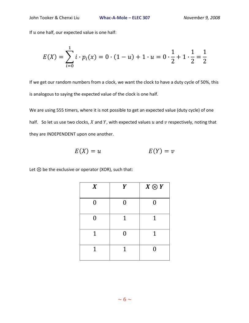
If one half, our expected value is one half:
If we get our random numbers from a clock, we want the clock to have a duty cycle of 50%, this
is analogous to saying the expected value of the clock is one half.
We are using 555 timers, where it is not possible to get an expected value (duty cycle) of one
half. So let us use two clocks, and , with expected values and respectively, noting that
they are INDEPENDENT upon one another.
Let be the exclusive or operator (XOR), such that:

John Tooker & Chenxi Liu Whac-A-Mole – ELEC 307 November 9, 2008
~ 7 ~
Then the expected value of is:
2
This says that if and are close to one half, then is even closer to one half.
We connected two 555 timers in Multivibrator mode, see Figure 2.
Figure 2
2 Robert B Davies, “Exclusive OR (XOR) and hardware random
number generators” February 28, 2002

John Tooker & Chenxi Liu Whac-A-Mole – ELEC 307 November 9, 2008
~ 8 ~
With component values and calculations3:
X Y
R1 220 Ω 220 Ω
R2 6.8 KΩ 1.0 KΩ
C1 2.2 nF 1.0 nF
Frequency 47.5 kHz 650 KHz
Expected Value ( ) 0.5080 0.5495
Therefore if we take our random bit value from , its expected value will be:
Which is very close to 0.5. This makes sense: our clocks are outputting a ‘1’ slightly more than
half of the time, which means there is a greater likelihood of getting , but also a less
likely change of getting .
Now we have a ‘random bit’ which is 1 close to half of the time. We just need to sample that
bit with another timer (we used the one that is on the Altera board: 25.175 MHz, down
3 http://www.ecelab.com/circuit-astable-555.htm
John Tooker & Chenxi Liu Whac-A-Mole – ELEC 307 November 9, 2008
~ 9 ~
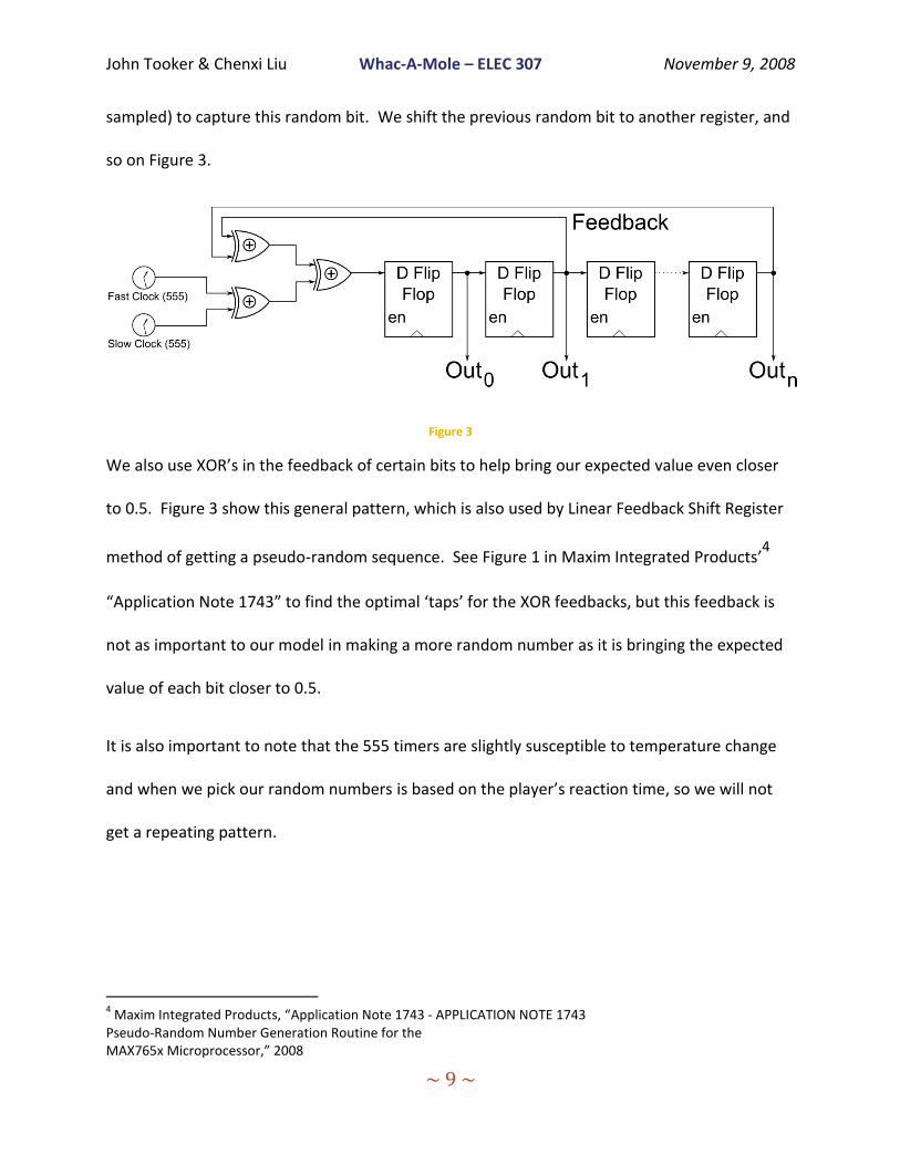
sampled) to capture this random bit. We shift the previous random bit to another register, and
so on Figure 3.
Figure 3
We also use XOR’s in the feedback of certain bits to help bring our expected value even closer
to 0.5. Figure 3 show this general pattern, which is also used by Linear Feedback Shift Register
method of getting a pseudo-random sequence. See Figure 1 in Maxim Integrated Products’4
“Application Note 1743” to find the optimal ‘taps’ for the XOR feedbacks, but this feedback is
not as important to our model in making a more random number as it is bringing the expected
value of each bit closer to 0.5.
It is also important to note that the 555 timers are slightly susceptible to temperature change
and when we pick our random numbers is based on the player’s reaction time, so we will not
get a repeating pattern.
4 Maxim Integrated Products, “Application Note 1743 - APPLICATION NOTE 1743
Pseudo-Random Number Generation Routine for the MAX765x Microprocessor,” 2008

John Tooker & Chenxi Liu Whac-A-Mole – ELEC 307 November 9, 2008
~ 10 ~
How the score machine work
When it is time for the mole to ‘pop up,’ (when we turn on that LED) we also load a ‘max score’
into a register and start counting down (subtracting one for every millisecond). When the
player hits the mole, this score will be added to the cumulative score. (See Figure 4 below)
Therefore, the quicker you hit the mole, the better your score will be. We are using UNSIGNED
numbers, so when the score that is being counted down hits zero, we stop (so we do not add a
larger amount when the player reacts really slow).
We keep track of four hex ‘digits’ worth of score, but only display the higher two. (So you could
get 0x0080 and 0x0090 which would be 0x00 if we kept only two digits, but since we keep all
four, is 0x01 (10) ).
Figure 4

John Tooker & Chenxi Liu Whac-A-Mole – ELEC 307 November 9, 2008
~ 11 ~
Procedure and Implementation:
We started by making a block diagram and state diagram to plan out our hardware behavior
(See Appendix A: Block Diagrams). We were going to use Altera’s Max 7000 PLD, but ran into
troubles when we could not drive multiple inputs from one output.
Switching to the Altera Flex 10K FPGA gave us greater flexibility to our design, allowing us to
implement our design without worry of board size limits. The switches, LED’s and 555 timers
were the only external architecture and were connected via wire to breadboard and using
soldering. We used a pizza box to contain our FPGA, switches, and other components.
The data path of our design we implemented in Quartus II’s schematic capture tool, the Control
logic was a combination of this and VHDL (a state machine and a separate state to control signal
decoder). In Figure 5 we can see our inputs (Clock time in milliseconds, reset, random time the
mole can be up, which (random) mole will be up and which switch is being pressed). We also
have a register to keep track of time: both how much time the mole has left to be up, as well as
how much time to wait between moles (1200 ms). The Mole Counter keeps track of how many
moles have been up, after 15 we know the game is done.

John Tooker & Chenxi Liu Whac-A-Mole – ELEC 307 November 9, 2008
~ 12 ~
Figure 5
John Tooker & Chenxi Liu Whac-A-Mole – ELEC 307 November 9, 2008
~ 13 ~
Results and discussion:
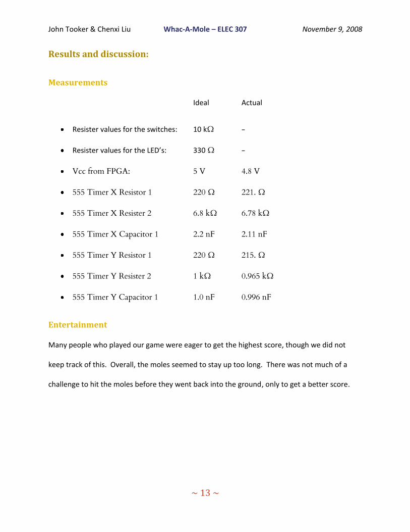
Measurements
Ideal Actual
Resister values for the switches: 10 kΩ -
Resister values for the LED’s: 330 Ω -
Vcc from FPGA: 5 V 4.8 V
555 Timer X Resistor 1 220 Ω 221. Ω
555 Timer X Resister 2 6.8 kΩ 6.78 kΩ
555 Timer X Capacitor 1 2.2 nF 2.11 nF
555 Timer Y Resistor 1 220 Ω 215. Ω
555 Timer Y Resister 2 1 kΩ 0.965 kΩ
555 Timer Y Capacitor 1 1.0 nF 0.996 nF
Entertainment
Many people who played our game were eager to get the highest score, though we did not
keep track of this. Overall, the moles seemed to stay up too long. There was not much of a
challenge to hit the moles before they went back into the ground, only to get a better score.
John Tooker & Chenxi Liu Whac-A-Mole – ELEC 307 November 9, 2008
~ 14 ~
Results vs. Expectations
Our results met our expectations. Our game worked just as we wanted it too. The only thing
that got in our way is that we needed to use another FPGA to implement our design.
For the random numbers, we were going to use memory filled with computer calculated (ahead
of time) random numbers. This was more accurate; less biased than the hardware methods.
But our original PLD did not support memory, and when we switched to the FPGA we kept with
the two timer method of random number generation.
Random Number Observation
In the dozens of games we played with our board, we have seen everything from getting a
different mole each time to getting the same one 5 times in a row. Other random number
generators repeat after some time (the LFSR based ones) and never have the chance of getting
the same number so many times in a row, but ours has does not have these draw backs. The
slight bias towards numbers that have more zeros in them (mole 0x0 = 000b, and 001b, 010b,
100b) was not noticeable, which supports our 0.4992% expected value (on average, out of
10,000 bits, there would be 8 more zeros than ones).
Figure 9 in Appendix B: Simulations shows how the random numbers might occur in a given
simulation.

John Tooker & Chenxi Liu Whac-A-Mole – ELEC 307 November 9, 2008
~ 15 ~
If we had more time
If we had more time we would have implemented:
Keeping track of high score
Multiple moles up at once (cannot do with decoder/encoder)
Making the moles come up quicker as the game goes on
Standards and Social Impact:
Whac-A-Mole is a game that entertains people. Though it will not change the way we live, the
game does test the player’s reaction time.
The typical game has the moles in the holes that could be up and down, but our Whac-A-Mole
game has LEDs and pushbutton to represent the moles and mallet. However, the missions of
both of them are to test people’s reaction time. The faster reactions, the better score you get.

John Tooker & Chenxi Liu Whac-A-Mole – ELEC 307 November 9, 2008
~ 16 ~
Conclusion:
Two 555 timers, a couple XOR gates and a few flip flops can yield exceptional random number
generation, with almost no bias and no pattern repetition. This can be use for just one bit or
many bits, representing everything from time to picking which event will take place (which
mole will pop up and how long it will stay up).
Our Wack-A-Mole game helped developed FPGA programming skills and taught as the value of
learning everything we can about the equipment we will use. We were lucky and had another
FPGA available when the first one did not meet our needs. The game was fun and used many
of the techniques and tools we used in the previous ELEC 307 labs.

John Tooker & Chenxi Liu Whac-A-Mole – ELEC 307 November 9, 2008
~ 17 ~
Appendix A: Block Diagrams
Figure 6
Here we see the data path. The switches, Slow and Fast Clocks and LED’s are external to the
FPGA board. The Seven Segment Displays and 1 ms clock are on the Altera board.
The Switches are active low, so we invert them and feed those signals before sending them to
the control unit. Random number generators (fed by the fast and slow clocks) generate which
mole is up and how long the mole should be up. This is monitored by the control unit to make
sure that the numbers are in the bounds we set.
The score is updated when the correct mole is hit. There is a down counter that counts down
for every microsecond you do NOT hit the mole after it pops up. If the counter reaches zero, it
does not go into negative numbers (we are using unsigned representations for our machine).
There is logic to translate hexadecimal signals to seven segment display outputs. The decoder
takes what mole is up and translates this to which LED should be lit. Only one can be up at the
same time.

John Tooker & Chenxi Liu Whac-A-Mole – ELEC 307 November 9, 2008
~ 18 ~
Figure 7
Here we use simple gate logic to determine if the time and moles are valid, as well if the switch
pressed is equal to the mole that is up. These signals, as well as if we have had 15 moles and if
our time is out (for the current mole) are fed into the state machine.
The state machine (see figure UPDATE ME on the next page) uses Moore State Machine VHDL
logic and these input signals to control which state we are in. The decoder takes the state and
outputs the correct control signals to the data path.
John Tooker & Chenxi Liu Whac-A-Mole – ELEC 307 November 9, 2008
~ 19 ~
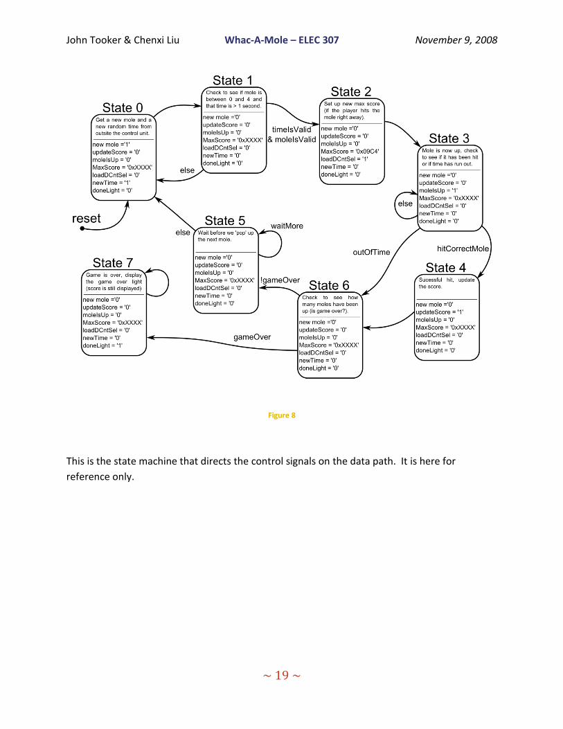
Figure 8
This is the state machine that directs the control signals on the data path. It is here for
reference only.

John Tooker & Chenxi Liu Whac-A-Mole – ELEC 307 November 9, 2008
~ 20 ~
Appendix B: Simulations
Figure 9
Here we can see different random numbers that occur with the clock frequencies and duty
cycles that match the ones used with our 555 timers.
John Tooker & Chenxi Liu Whac-A-Mole – ELEC 307 November 9, 2008
~ 21 ~
Appendix C: References
Whac-a-Mole background
http://en.wikipedia.org/wiki/Whac-a-mole
Less Biased random numbers
Robert B Davies, “Exclusive OR (XOR) and hardware random number generators” February 28, 2002
555 timer multivibrator setup
http://www.ecelab.com/circuit-astable-555.htm
Optimal Feedback in Linear Feedback Shift Register
Maxim Integrated Products, “Application Note 1743 - APPLICATION NOTE 1743 Pseudo-Random
Number Generation Routine for the MAX765x Microprocessor,” 2008