Education You Can Build On Emerson 12” Series Thermostats Homeowner Support Hotline: 800-284-2925...
35
Education You Can Build On Emerson 12” Series Thermostats Homeowner Support Hotline: 800-284-2925 Education Central Engage, Apply, Retain Note: This module covers common elements. Refer to Specification Sheet or Installation Instructions for detailed information.
-
Upload
shane-bartholomew -
Category
Documents
-
view
216 -
download
1
Transcript of Education You Can Build On Emerson 12” Series Thermostats Homeowner Support Hotline: 800-284-2925...

Education You Can Build On
Emerson 12” SeriesThermostats
Homeowner Support Hotline:
800-284-2925
Education CentralEngage, Apply, Retain
Note: This module covers common elements. Refer to Specification Sheet or Installation Instructions for
detailed information.
Emerson 12” ThermostatsSelecting the Right Thermostat for the Job
Application Coverage by System
ModelStages
Heat / Cool by System
Applications Programming Options Power Source
Single Stage (SS) Multi-Stage (MS) Heat Pump (HP1 or HP2)
Universal (All)
Model Number
Single Stage
Multi-Stage
Heat
Pump
Gas/Oil/Electric
3-Wire Zon
e Valu
e
Millivolt Compatible
Humidity Control
Program Days per Week
Program Periods per Day
Hardwire Battery
Power Assist
Universal
1F98EZ-1441Easy Install 1/1 2/2 4/2 ✓ H,D 7, Ø 4, Ø H
1F95-1291Humidity 1/1 2/2 4/2 ✓ ✓ ✓ H,D 7, 5+1+1, Ø 4, 2, Ø B,H,PA
1F95-1280 Commercial 1/1 2/2 4/2 ✓ ✓ ✓ 7, 5+1+1, Ø 2, Ø B,H,PA
1F95-1277 1/1 2/2 3/2 ✓ ✓ ✓ 7, 5+1+1, Ø 4, 2, Ø B,H
Single Stage / Heat Pump 1F97-1277 1/1 2/1 ✓ ✓ ✓ 7, 5+1+1, Ø 4, 2, Ø B,H
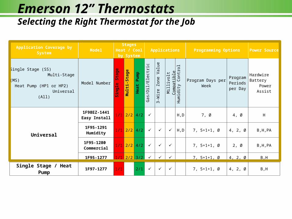
• Applications
• Wiring
• Configuration
• Programming• Featured Products In This Module
– 1F98EZ-1441• 4 Wire Universal
– 1F95-1291• Humidity Thermostat, Universal
– 1F95-1277• Touchscreen, Universal
12” Series Thermostats Agenda
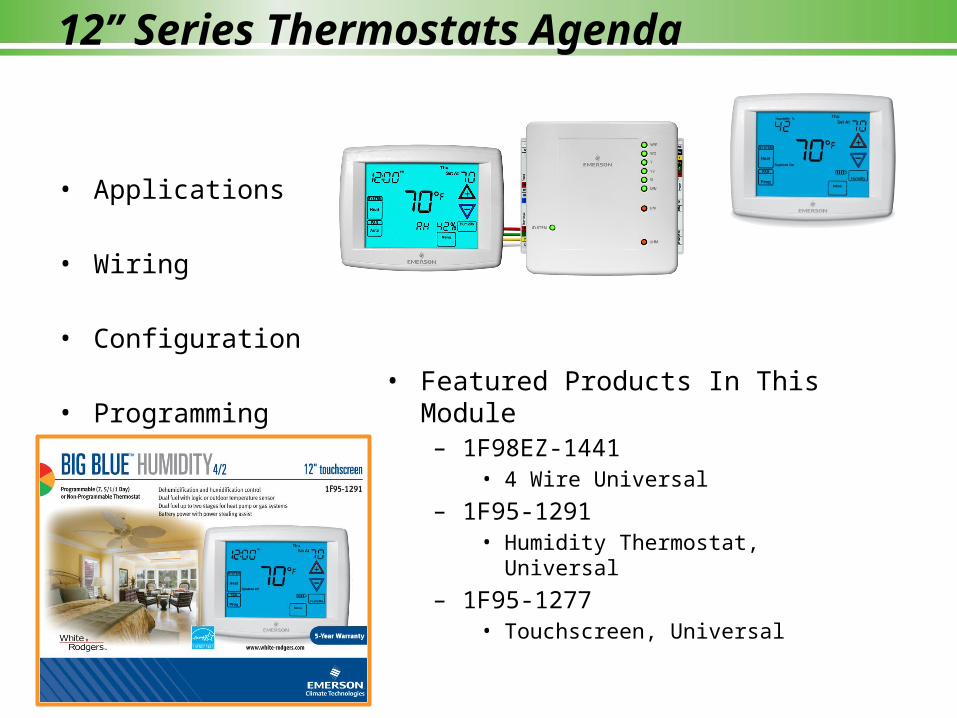
Staging By System TypeProgramming OptionsApplications
Terminal IdentificationPart Number
Look at the Box for Detailed Information
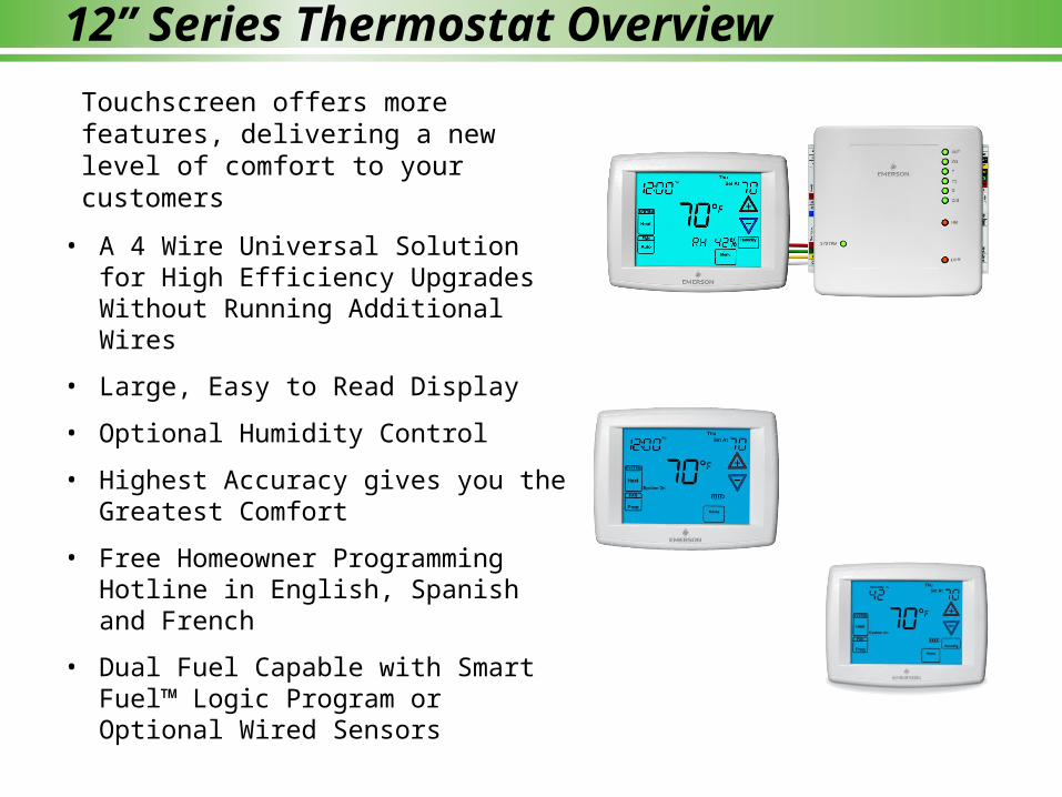
• A 4 Wire Universal Solution for High Efficiency Upgrades Without Running Additional Wires
• Large, Easy to Read Display
• Optional Humidity Control
• Highest Accuracy gives you the Greatest Comfort
• Free Homeowner Programming Hotline in English, Spanish and French
• Dual Fuel Capable with Smart Fuel™ Logic Program or Optional Wired Sensors
12” Series Thermostat Overview
Touchscreen offers more features, delivering a new level of comfort to your customers

12” SeriesSpecification Sheets Contain Detailed Information

12” Series Applications
Application Stages Programming Feature Type
Universal
4/2 7, 0 Easy Install 4 Wire 1F98EZ-1441
4/2 7, 5+1+1, 0 Humidity 1F95-1291
4/2 7, 5+1+1, 0 Commercial 1F95-1280
3/2 7, 5+1+1, 0 12" Touchscreen 1F95-1277
Conventional or Heat Pump with Aux
2/1 7, 5+1+1, 0 12" Touchscreen 1F97-1277
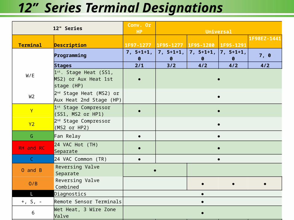
12” Series Terminal Designations 12" Series Conv. Or HP Universal
Terminal Description 1F97-1277 1F95-1277 1F95-1280 1F95-1291 1F98EZ-1441
Programming 7, 5+1+1, 0 7, 5+1+1, 0 7, 5+1+1, 0 7, 5+1+1, 0 7, 0
W/E
Stages 2/1 3/2 4/2 4/2 4/2
1st. Stage Heat (SS1, MS2) or Aux Heat 1st stage (HP)
● ●
W2 2nd Stage Heat (MS2) or Aux Heat 2nd Stage (HP)
●
Y 1st Stage Compressor (SS1, MS2 or HP1)
● ●
Y2 2nd Stage Compressor (MS2 or HP2)
●
G Fan Relay ● ●
RH and RC 24 VAC Hot (TH) Separate ● ●
C 24 VAC Common (TR) ● ●
O and B Reversing Valve Separate ●
O/B Reversing Valve Combined ● ● ●
L Diagnostics ●
+, S, - Remote Sensor Terminals ●
6 Wet Heat, 3 Wire Zone Valve ●
Hum, Dehum(2) Humidity Terminals ● ●
A1 Economizer ●
Note:Touchscreen Single Stage
Touchscreen Mutli-Stage
Commercial Humidity Wireless

12” Series Heat Pump / Dual Fuel Staging Detail
Stage+HP1
Heat ModeHP2
Heat Mode
HP1 w/2 stage Dual Fuel
Heat Mode
1st Y1 Compressor Y1 Compressor Y1 Compressor
2nd W/E Aux, stage 1 Y2 Compressor Y2 Compressor
3rd W2 Aux, stage 2 W/E Aux, stage 1 W/E 1st Stage Gas
4th W2 Aux, stage 2 W2 2nd Stage Gas
Dual fuel option de-energizes any compressor stage when auxiliary heat is energized

• Power Stealing Assist extends battery life significantly by drawing “stealing” small amounts of voltage from the heat (W) or cool (Y) circuit. Power Stealing Switches on the back of the thermostat should be left in the “ON" position for most systems.
• On a small number of heating or cooling systems with high impedance electronic modules you may observe one of the following conditions:– The furnace , draft inducer or fan run or continue running when the
thermostat is not calling for operation. Switch the “W” dip switch to OFF. – If the condition continues to occur switch the “Y” dip switch to OFF to
disable Power Stealing Assist completely and operate the thermostat on batteries only.
Power Stealing Assist Extends Battery Life (1F95 -1291 and 1280 Only)
If the Power Stealing Assist method is not compatible with your system both switches can be turned off and the thermostat will operate normally.

12” Series Wiring for Conventional Systems- AC /Furnace (No Heat Pump)
* Common connection requited for the 1F98EZ, diagnostic indicator, and outdoor sensor options. Optional on others.
** For two transformer systems remove the jumper
#6 Terminal is for a power
closed 3 wire zone
valve
Single Stage (SS) in RedMulti-Stage (MS) add Orange

12” Series Wiring for Heat Pump
* Common connection requited for the 1F98EZ, diagnostic indicator, and outdoor sensor options. Optional on others.
** For two transformer systems remove the jumper*** If your system does not provide an E connection, jumper W2 to
W/E to use the Auxiliary Heat in the Emergency Mode
Dual fuel option de-energizes
when auxiliary heat is
energized
Single Stage Heat Pump (HP1) in GreenMulti-Stage Heat Pump (HP2) add Orange

12” Series Navigation
Heat/Cool/Off
Fan Auto/On
Configuration and Programming Touchpad's
Temperature or Configuration
Adjustment Buttons
Actual Room Temperature
Desired TemperatureTime of Day or
Humidity
Day of Week
Battery Status = Full Charge = Half Capacity = Replace Batteries
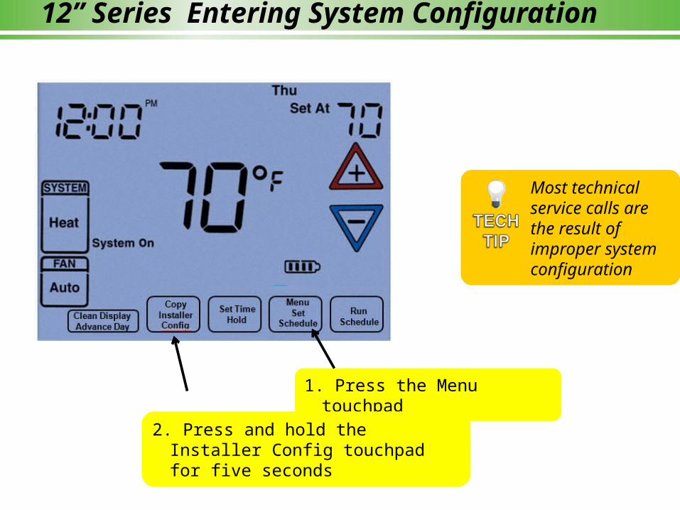
12” Series Entering System Configuration
Most technical service calls are the result of improper system configuration
1. Press the Menu touchpad
2. Press and hold the Installer Config touchpad for five seconds

12” Application Specific versus Customization—Don’t Go Overboard!
MENU ITEMDISPLAY
(DEFAULT) OPTIONS COMMENTS
System Configuration (MS 2)SS1, MS2, HP1, HP2
Installer Set
Electric Heat Fan (GAS) GAS, ELE Installer Set
1. Choose System
2. Select Fan Function
Options are great but know the difference between application, options, and confusion to the homeowner.

1F95-1277 Series Configuration ExampleRefer To Installation Instructions For Other Models
Denotes Critical to the Application
Menu # P N-P
Displayed (Default)
Press Δ or to Select From Listed
Options Comments
1 1 1 SS1 HP1, SS1Selects Single Stage or Heat Pump (1 compressor), on the
1202 and 1202H add MS2 and HP2 to choices
2 2 2 (ELE) GASGAS setting: furnace controls blower ELE setting: thermostat
controls blower
3 3 3 Days, (7) P 5+1+1 or 0 Programs per week . (0 = non-programmable)
4 4 NA PS (4) 2 Program periods per day
5 5 4Cool-Off- Heat-Auto
Cool-Off-Heat, Off-Heat, Cool-Off
System switch configuration in single stage
6 6 NA E (On) OFFSelects Energy Management Recovery, E (with programming
option on)
7 7 5 Cr, Heat (FA) SL Selects Adjustable Anticipation, cycle rate, Heat
8 8 6 Cr, Cool (FA) SL Selects Adjustable Anticipation, cycle rate, Cool
9 9 7Cr/AU, Emer
(FA)SL
Selects Adjustable Anticipation, cycle rate auxiliary, (This item is only to appear if HP1 is selected above)
10 10 8 CL (OFF) On Selects Compressor Lockout

Menu # P N-P
Displayed (Default)
Press Δ or to Select From Listed
Options Comments
11 11 9 dL (On) OFF Selects Continuous Display backlight & intensity
12 12 10 dL (LO) HI Selects Backlight Intensity
13 13 11 0 -4, LO to 4, HI Selects Adjustable Ambient Temperature Display
14 14 12 °F °C Selects °F/°C Display (temperature units in Fahrenheit or Celsius) .
15 15 13 b (On) OFF Selects audible Beeper On/Off
16 16 14 dS (On) OFF Selects Daylight Saving Time calculation
17 17 15 AS, Heat (On) OFFSelects Automatic Schedule for comfort temperature Programming,
heat mode
18 18 16 AS, Cool (On) OFFSelects Automatic Schedule for comfort temperature Programming,
cool mode
19 19 17CS, (OFF)
Cool Savings1-2-3-4-5-6 Selects Cool Saving Feature & amount
1F95-1277 Series Configuration Refer To Installation Instructions For Other Models
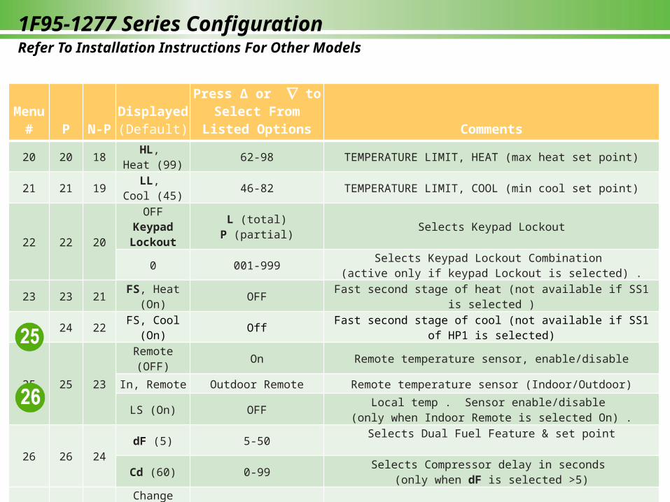
Menu # P N-P
Displayed (Default)
Press Δ or to Select From Listed
Options Comments
20 20 18HL,
Heat (99)62-98 TEMPERATURE LIMIT, HEAT (max heat set point)
21 21 19LL,
Cool (45)46-82 TEMPERATURE LIMIT, COOL (min cool set point)
22 22 20
OFFKeypad Lockout
L (total)P (partial)
Selects Keypad Lockout
0 001-999Selects Keypad Lockout Combination
(active only if keypad Lockout is selected) .
23 23 21 FS, Heat (On) OFF Fast second stage of heat (not available if SS1 is selected )
24 24 22 FS, Cool (On) Off Fast second stage of cool (not available if SS1 of HP1 is selected)
25 25 23
Remote (OFF) On Remote temperature sensor, enable/disable
In, Remote Outdoor Remote Remote temperature sensor (Indoor/Outdoor)
LS (On) OFFLocal temp . Sensor enable/disable
(only when Indoor Remote is selected On) .
26 26 24dF (5) 5-50
Selects Dual Fuel Feature & set point
Cd (60) 0-99Selects Compressor delay in seconds
(only when dF is selected >5)
27 27 25
Change Filter (OFF)
On Selects Change filter feature
200 Hours 25-1975Change filter, duration hours (in increments of 25 hours)
1F95-1277 Series Configuration Refer To Installation Instructions For Other Models

Optional Configuration Options
MENU ITEMDISPLAY DEFAULT OPTIONS COMMENTS
EMR E (On) OffProgramming Mode Only
Heat Cycle Rate Cr HEAT (ME) SL, FA SS1, MS2 only
Heat Pump Configuration Cycle Rate
Cr Heat / A/C (ME)
SL, FAHeat PumpHP1, HP2 only
A/C Cycle Rate Cr A/C (ME) SL, FA SS1, MS2 only
Auxiliary Heat Cycle Cr AUX Heat (FA) SL HP1, HP2 only

Optional Configuration Options
MENU ITEM DISPLAY DEFAULT OPTIONS COMMENTS
Compressor Lock-out CL (OFF) On Installer Set
System Configuration (Heat, A/C, Off)Heat, Off, Fan/Heat, Off/ A/COff
Installer Set
Compressor Optimization
CO (OFF) On Installer Set
LCD Display Light dL(ON) OFF
Temperature Display Adj.
Hi (0) 1 to 5 Hi or LO
°F/°C Selection (°F) °C

Optional Configuration Options
MENU ITEMDISPLAY
(DEFAULT) OPTIONS COMMENTS
Dual Fuel / Electric dF (0) 1 – 9
Compressor Delay Cd (60) 00 – 99
O/B Output Configuration
On A/C (O) On Heat (B)
Application Specific Set By Installer (HP1 or HP)

1F95-1291 Humidity Thermostat Configuration, Additional Menu Items
Menu #
SS1MS2
HP1HP2
Displayed (Default)
Press Δ or to Select From Listed
Options Comments
38 l l (OFF) Hd On Selects Humidity Display alternate with time.
39 l lHumidity 00
(Room Humidity)
-20 Lo to 20 HI Selects Humidity Display adjustment.
40 l l (OFF) HR LO, HI Selects Auto Humidity reduction.
41 l l (OFF) AH H, C, A Selects Automatic Humidification.
42 l l (OFF) CH On Selects Cycle Humidifier.
43 l l OC (0) od, OFF Selects Optimum Comfort or Optimum Dehumidification or Off.
44 l l (OFF) Change UV Lamp
On Selects Change UV Lamp feature.
45 l l 350 Days 25-1975 Change UV Lamp duration days.
46 l l (OFF) Change Pad
On Selects Change Humidifier Pad feature.
47 l l 100 Hrs 25-1975 Change Humidifier Pad duration hours.

12” Series Reset to Factory Defaults
Factory Default Reset: to completely reset the programming, clock and Configuration Menu to the Factory Default Settings, press the UP, DOWN, and SYSTEM touchpad's simultaneously. The display will
go black for a few seconds, and then all segments will display momentarily. Reset settings for the application.

12” SeriesProgramWorksheet
Technical Service has never spoken to anyone who could not program the thermostat once they filled out the schedule worksheet in the manual and KEPT it. Save a call back and fill it out with the homeowner. Ensure they have the Homeowner Support Hotline: 888-616-0030
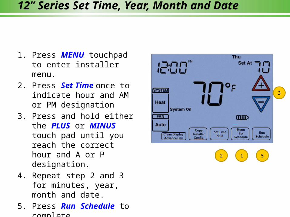
12” Series Set Time, Year, Month and Date
1. Press MENU touchpad to enter installer menu.
2. Press Set Time once to indicate hour and AM or PM designation
3. Press and hold either the PLUS or MINUS touch pad until you reach the correct hour and A or P designation.
4. Repeat step 2 and 3 for minutes, year, month and date.
5. Press Run Schedule to complete
12
3
5

12” Series Automatic Daylight Saving Calculator
The Real Time Clock will adjust automatically for daylight savings time, in the following manner:– Increment one hour at 2 AM on the second Sunday of March and
decrement one hour at 2 AM on the first Sunday of November.
The daylight saving feature can be enabled or disabled in installer configuration mode. Default is dS ON (enabled).
After entering installer configuration mode, momentarily press or touch + or -key until the display indicates dS (in actual temperature digits) and on (default – in clock digits).
• Press the + or - keys to toggle display and operation from On to Off

12” Series Program Copy Button
• You may copy any daily program to another day or group of days by pressing the Copy touch pad. In 7 day programming mode when the Copy button is pressed, the other 6 days of the week will flash.
1. To copy the current program into the remaining six days, simply press the Copy button again.
2. To copy the current program to another day of the week, press Advance Day to select the day and press Copy to paste the program.
• In 5+1+1 day programming mode the copy function is similar. The weekday (Mon-Fri) program can be copied to Sat and Sun (both flashing) or use Advance Day to choose Sat or Sun and press Copy to paste the program.
12” Series Configure Program Options
• System must be set for Heat or Cool. Press the Menu button for at least 5 seconds.1. The display will step #1 in the configuration menu
2. Press the UP button to the appropriate configuration Menu No • Select the programs per week by pressing UP/DOWN button
– “0” for non-programmable– “5+1+ 1” for Mon through Fri with independent Sat. and Sun programs.– “7” for independent program days
3. Press the UP button to the next configuration Menu No • Select the programs per day by pressing UP/DOWN button• “2” for Morn/Eve program periods per day • “4” for Morn/Day/Eve/Night program periods per day
4. Press Run

12” Series How to Set A Program
1. Press the Menu button and then press Set Schedule. Press SYSTEM button to select either "Heat" or "Cool” in the system switch area indicating the active mode being programmed.
2. The top of the display will show the day(s) being programmed. The time and set at temperature are also displayed. "Morning" will also be displayed to indicate the period.
3. Press PLUS or MINUS touch pad to change the temperature to your selected temperature for the 1st heating period (Morning).
4. Press PLUS or MINUS touchpad to adjust the start time for period. The time will change in 15 minute increments.
5. Press FAN to select Auto or Prog.
6. Press Set Schedule to advance to the next program period.
7. Repeat steps 2 through 6 until all of the program times and temperatures are set for all program periods on that day.
8. Press "Advance Day" to change to the next day and repeat steps 2 through 8.
9. Press Run Schedule To complete programming.

12” Series Automatic Scheduling
• This feature provides a method to program every day with the most popular time and temperature profile using one key press.
• For this feature to be available, the Auto schedule options (AS Cool or AS Heat) should be set on in the installer configuration. – Select the desired “Comfort Temperature” in the setpoint. When the Auto
Schedule touch key is pressed, it will start flashing indicating that it is now ready to insert the displayed temperature setpoint as the “Comfort Temperature” for the selected system mode currently in (Heat/Cool).
– A second press of the Auto Schedule touch key will complete the process. A 6 °F setback temperature will also be inserted for the night step.
– Once complete, the touch key display Auto Schedule will disappear disabling any further operation of Auto Schedule touch key. If desired it can be enabled again in the installer configuration menu.

12” Series Entering Fan Program
• In the Set Schedule mode, the FAN key is used to select the fan operation during a program period. The default state of the Fan key is FAN Auto (fan runs during a call for cool but not on a call for heat).
• It can be changed to FAN Prog (fan runs during a program period). Each press of the FAN key will change the mode of the fan between Auto and Prog.
• In the Run mode, when a program period that has FAN Prog begins, the fan will turn on and stay on during the complete period. The display will show FAN On Prog.
• Pressing the FAN key will change FAN On Prog to On (fan running continuously) or Auto. To return to FAN On Prog, press Run Schedule.
12” Series Dual Fuel Settings
• This feature is applicable only in heat pump modes and an outside remote sensor is installed, the thermostat can monitor the outside temperature. – When the outside temperature falls below the selected setpoint
temperature, dF, the thermostat will switch to gas heat and shut down the compressor. The eliminates the need for a fossil fuel kit.
– Use the or PLUS or MINUS touchpad's to select the desired setpoint temperature in the range of 5° F to 50° F
– Factory default is 5, which disables this feature. See Dual Fuel Temperature and Setpoint in Programming section.
• Select Compressor Delay – When dF is enabled, the shut down of the compressor(s) is delayed for a time period after the auxiliary stage is energized. This delay, Cd, is factory set at 60, but can be set in the range of 0 to 99 seconds by using the PLUS or MINUS touchpad's .

12” Series Wired Remote Sensing
• One remote temperature sensor can be installed indoor or outdoor and connected to the thermostat by a maximum cable length of 100 meters (300 ft). Three terminals, +, S & - are provided on the terminal block to connect to the White- Rodgers standard wired remote sensor. This sensor will be read by the thermostat only when 24 VAC is present.
• When used as indoor sensor, the readings can be weighted with the local sensor for specific program periods. User can enable or disable the remote sensor in the installer configuration mode and also the outdoor temperature can be selected to show on the display.
• In the installer configuration mode, momentarily press the PLUS or MINUS touchpad until display indicates Remote (at the top left of the LCD) and OFF (default – in clock digits).
– Pressing PLUS or MINUS touchpad will toggle the operation and display from Remote OFF to Remote On.
– When Remote On is selected, press the PLUS touchpad for the display to indicate Remote In (for indoor remote). The or keys will toggle the operation and display from Remote In to Outdoor Remote. When any remote is selected the temperature will display in the clock digits for one second alternating with the current time for three seconds when in Run Schedule mode. Outdoor Remote will indicate at the top left of display for outdoor remote reading. Only Remote will show at top left for indoor remote reading. (°F or °C will not indicate with remote temperature readings).
• Sensing Range:– Outdoor temperature range is -40 to 140°F– Indoor temperature range is 32 to 99 °F
12” Changing Humidity Settings
• Heat (Humidification)– Press SYSTEM key to select HEAT. – To change the humidity setting when System On appears and the heating
system is running press the HUMIDITY* button once.– Press UP or DOWN to adjust the humidity level setpoint range. (Humidity
setpoint can be adjusted from 5 to 50%.) Hum On will appear indicating it is calling for the humidifier.
• Cool (Dehumidification)– Press SYSTEM to select Cool.– To change the humidity setting when System On appears and the cooling
system is running press the HUMIDITY* button once.– Press UP or DOWN to adjust the dehumidification level setpoint range. (Humidity
setpoint can be adjusted from 5 to 50%.) DeHum On will appear indicating it is calling for the humidifier.
– If the room humidity is lower than the adjustment range, press DOWN to 40% and hold for 4 seconds. This will force the DeHum On for one complete cooling cycle to test the dehumidification equipment.
• *Note: If Auto Schedule is displayed instead of Humidity, Auto Schedule must be turned off in the Configuration Menu.

12” Emergency Mode for Heat Pumps
• Emergency Heat (System EM Position) bypasses the Heat Pump to use the heat source wired to terminal W/E, W2 on the thermostat. EM is typically used when compressor operation is not desired, or you prefer back-up heat only.
1. Press SYSTEM key to select EM. “EM Heat Mode” will flash on the display.
2. Press UP or DOWN to adjust thermostat setting above room temperature.– The Emergency heating system will begin to operate. The display will
show “System On” flashing “EM Heat Mode” and “Heat” to indicate that the Emergency system operating.
3. Adjust temperature setting to 3° above room temperature.– Any additional stages of auxiliary heat should begin to operate and the
display will show "System On +2".
4. Press UP or DOWN to adjust the thermostat below room temperature.– The heating system should stop operating.